Embed Size (px)
Citation preview

DIESEL GENERATING SET
Single-phase:
Three-phase:
KDE9000SS KDE11SS
KDE13SS KDE16SS
KDA9000SS K DA9000SSO
KDA11SS K DA11SSO
KDA13SS K DA13SSO
KDA16SS K DA16SSO
KDE9000SS3 KDE13SS3
KDE15SS3 KDE20SS3
KDA9000SS3 KDA9000SSO3
KDA11SS3 KDA11SSO3
KDA13SS3 KDA13SSO3
KDA16SS3 KDA16SSO3
WUXI KIPOR POWER CO., LTD.
Preface
Warning
Please read this instruction and ensure understand all regulations concerning
handling, check and maintenance thoroughly prior to application.
Failure to follow this instruction may cause serious accidents.
Incorrect operation is likely to lead accidents.
Operate and maintain the machine on the basis of thorough understanding of this
instruction.
Place this instruction in the fitting box or near machine after reading because it
is regularly needed.
If this introduction is lost or damaged, please order one from local KIPOR
dealer.
Please provide this introduction to another user whom machine will be
transferred to.
Machine may be improved or modified. Therefore actual conditions may be
different from this introduction.
If you have any doubt, please consult local KIPOR dealer.
Machine is the special diesel generator for ground application.
Safety information contained in this introduction are extremely important.
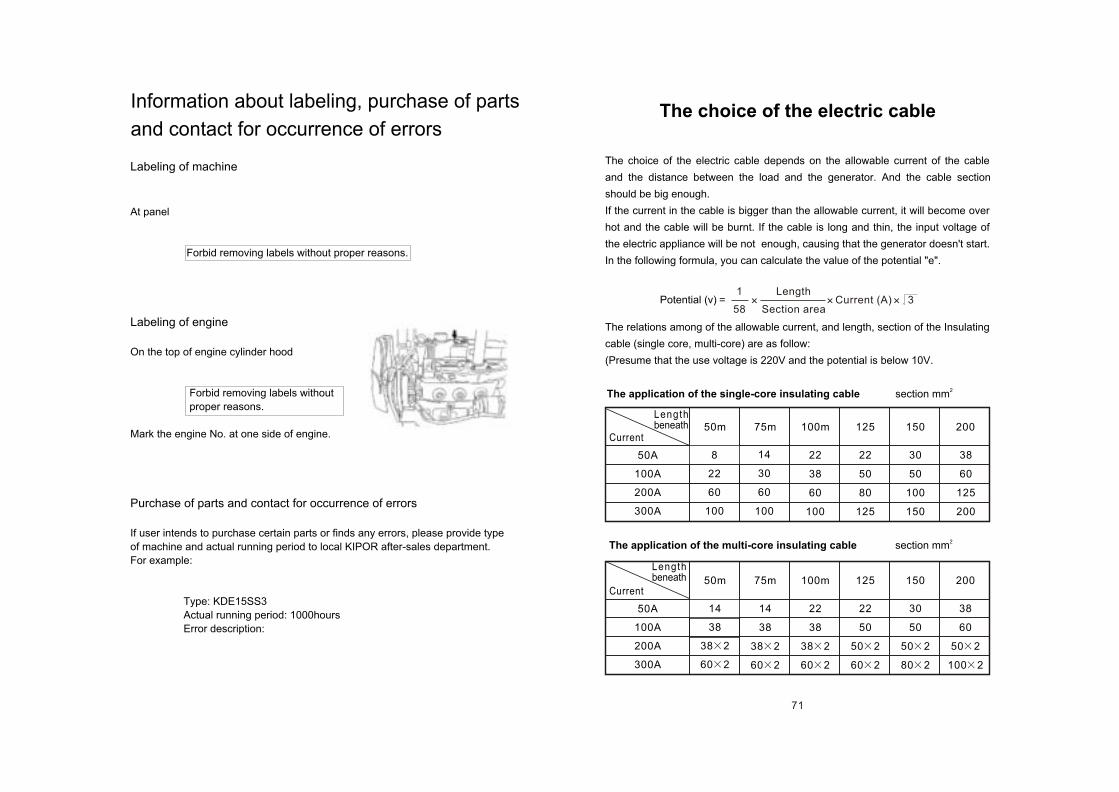
Labeling of machine
At panel
Forbid removing labels without proper reasons.
Labeling of engine
On the top of engine cylinder hood
Forbid removing labels without
proper reasons.
Mark the engine No. at one side of engine.
Purchase of parts and contact for occurrence of errors
If user intends to purchase certain parts or finds any errors, please provide type
of machine and actual running period to local KIPOR after-sales department.
For example:
Type: KDE15SS3
Actual running period: 1000hours
Error description:
Information about labeling, purchase of parts
and contact for occurrence of errors
The choice of the electric cable depends on the allowable current of the cable
and the distance between the load and the generator. And the cable section
should be big enough.
If the current in the cable is bigger than the allowable current, it will become over
hot and the cable will be burnt. If the cable is long and thin, the input voltage of
the electric appliance will be not enough, causing that the generator doesn't start.
In the following formula, you can calculate the value of the potential "e".
The relations among of the allowable current, and length, section of the Insulating
cable (single core, multi-core) are as follow:
(Presume that the use voltage is 220V and the potential is below 10V.
2The application of the single-core insulating cable section mm
2The application of the multi-core insulating cable section mm
The choice of the electric cable
Potential (v) = Current (A) 3Length
Section area
1
58
50A
100A
200A
300A
Current
Lengthbeneath 75m 125 20015050m 100m
8
22
60
100
14
30
60
100
38
60
125
200
22
38
60
100
22
50
80
125
30
50
100
150
50A
100A
200A
300A
Current75m 125 20015050m 100m
14
38
38 2
60 2
14
38
38 2
60 2
22
38
38 2
60 2
22
50
50 2
60 2
30
50
50 2
80 2
38
60
50 2
100 2
Lengthbeneath
71
Content
1. Safety
1.1 Safety marks
1.2 Attentions
1.3 Warning labels
2. Machine introduction
2.1 Use and laws
2.2 Main technical parameters
2.3 Outlook and parts' names
2.4 Structure
2.5 Operation panel
2.5.1 Configuration and name
2.5.2 Functions and operation introduction
2.5.3 Functions and identification of protectors
3. Connection of load
3.1 Capacity of motor
3.2 Selection of 3-phase cable
3.3 Connection of loading equipment
3.3.1 3-phase power supply (400V/415V)
3.3.2 Single-phase power supply (120V/240V)
3.3.3 Connect loading equipment
3.3.4 Low-load operation
3.4 Earth
4. Transportation and overlapping-storage
4.1 Lifting attentions
4.2 Transportation attentions
4.3 Overlapping-storage attentions
5. Installation
6. Operation
6.1 Fuel, lubricant and cooling water
6.1.1 Fuel
6.1.2 Lubricant
6.1.3 Cooling water
1
1
2
7
11
11
12
17
18
19
19
20
22
23
23
24
25
25
25
27
27
27
29
29
29
30
31
33
33
33
34
34
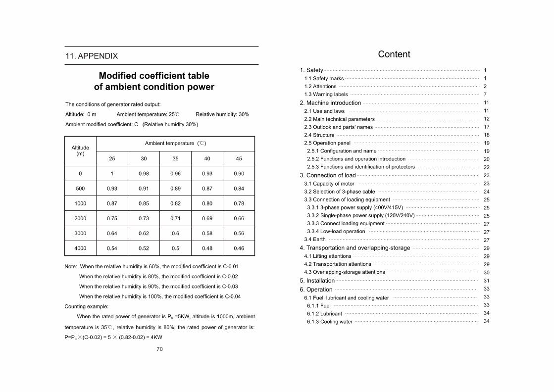
The conditions of generator rated output:
Altitude: 0 m Ambient temperature: 25 Relative humidity: 30%
Ambient modified coefficient: C (Relative humidity 30%)
Note: When the relative humidity is 60%, the modified coefficient is C-0.01
When the relative humidity is 80%, the modified coefficient is C-0.02
When the relative humidity is 90%, the modified coefficient is C-0.03
When the relative humidity is 100%, the modified coefficient is C-0.04
Counting example:
When the rated power of generator is P =5KW, altitude is 1000m, ambient N
temperature is 35 , relative humidity is 80%, the rated power of generator is:
P=P (C-0.02) = 5 (0.82-0.02) = 4KWN
Modified coefficient table of ambient condition power
Ambient temperature ( )Altitude
(m)
0
500
1000
2000
3000
4000
25
1
0.93
0.87
0.75
0.64
0.54
30
0.98
0.91
0.85
0.73
0.62
0.52
35
0.96
0.89
0.82
0.71
0.6
0.5
40
0.93
0.87
0.80
0.69
0.58
0.48
45
0.90
0.84
0.78
0.66
0.56
0.46
70
11. APPENDIX
6.2 Operation of storage battery
6.2.1 Check of storage battery
6.2.2 Charging attentions
6.3 Pre-start preparations
6.3.1 Fill fuel
6.3.2 Keynotes for filling fuel with outside fuel tank
6.3.3 Fill lubricant
6.3.4 Fill cooling water
6.3.5 Trial running
6.3.6 Quantity re-confirmation of lubricant and cooling water
6.4 Operation
6.4.1 Pre-start checks
6.4.2 Adjustment upon start and no-load
6.4.3 Keynote for load running
6.4.4 Stop the machine
6.4.5 Running on the automobile
6.4.6 Start procedure
6.5 Long-term storage
7. Maintenance and check
7.1 Check
7.1.1 Torque list
7.2 Periodical checks and intervals
7.3 Periodical check
7.3.1 Per 50hours
7.3.2 Per 250 hours
7.3.3 Per 500hours
7.3.4 Per 1000hours
7.3.5 Per 2000hours
8. Error-shooting
9. Electrical wiring drawing
9.1 Wiring drawing of generator
9.2 Wiring drawing of engine
9.3 Fuel system drawing
9.4 Lubricant system drawing
10. Warranty statement
11.Appendix
69
10. Warranty statement
Below things can't be guarantee repaired.Aging after a period of time, such as nature fading on cover of decorated dope and plated metal.General feeling phenomenons which don't affect quality and performance, such as sound, shock, etc. Problems brought by typhoon or flood.Problems brought by medicine or salt damage.
Cost of below things is not paid.Expendable, such as spark plug, air cleaner, fuel filter, lamp, tie plate, seal washer, fuse, and brush and grease and so on.Repair machine not in KIPOR generator service store or store where you bought the machine.
Check, clean, adjust and maintain timely.Inconvenient and loss brought by can't work, such as shutout or business loss.Compensate cost beyond instruction in this warranty statement.
Guarantee rangeThis guarantee is just for generator bought inland, and will be end if bring abroad.
Ways to receive guarantee repair.Please bring generator, warranty statement and invoice to the store you bought the machine or KIPOR generator service store to get guarantee repair. We will not provide guarantee repair if you don't bring with warranty statement.
Guarantee repair go into effect.The guarantee repair goes into effect as soon as you and the supplier write down some important terms on the warranty statement and sign or seal.
Thank you for buying
Guarantee termThe term of guarantee repair starts from the day you bought the machine and lasts one year. But if machine is long-term or frequently used, the guarantee term will be six months.Other guarantee things Battery will be guaranteed according to standards made by the accessory producers. Please consult with the store you bought the machine or KIPOR generator service store. (Only for generators with battery).
Things which can't be guaranteedErrors caused by below reasons can't be guarantee repaired.
Fail to check and maintain machine timely according to the instruction. Fail to operate according to the instruction.Badly or wrongly maintain.Over-time work.Change without promise of KIPOR.Error caused by inattentionUse anti-purity accessory or discommend grease.
KIPOR products, if disqualification happens to your generator sets, our company will ensure below followings according to this warranty statement.
Guarantee contentOur company will provide free repair if material or product disqualification happen to the genuine part of your generator. (Free repair is called guarantee repair in below passage, which means change and repair the parts). In addition, the disqualification parts will belong to KIPOR.
WUXI KIPOR POWER CO.LTD
Beside jingyi Rd, Third-stage Development section of Wangzhuang Industry Area.
Wuxi High & New Technology Industry Development Zone.
Tel: 0086-510-85205041
Fax: 0086-510-85203796
E-MAIL: [email protected] [email protected]
35
36
36
37
37
37
38
38
39
39
40
40
42
42
44
44
45
46
47
47
48
49
51
51
53
54
56
57
58
63
63
66
67
68
69
70
Warning
Attended
Danger
1
Warning
[Attended operation]
Indicate that mechanical damage or shorter duration and etc. is likely to occur in case of neglect.
However, it is impossible for our company to expect all risks concerning conditions of operation, check and maintenance. Therefore warnings contained in the introduction and identified on the machine are exclusive and complete. User shall take own responsibility for safety if user does operation, check and maintenance not mentioned herein.
1. Safety
Please read and observe all safety and precaution
information. Failure to observe them and incorrect
operation can lead to serious injury even death.
1.1Safety marks
Please carefully read and thoroughly understand this introduction and
precautions and attentions marked on the machine prior to operation, check and
maintenance. Then official operation is allowed.
Identify conditions of risks and damages if operation is incorrect with following
Indicates the extreme risk. Incorrect operation can lead to
serious injury even death.
Indicates the potential risk. If no measures are taken to
avoid risk, serious injury even death is very likely to occur.
Attention reminds operator not to ignore potential risks. If no
measures are taken to avoid risk, mild or moderate injury or
mechanical damage is very likely to occur.
68
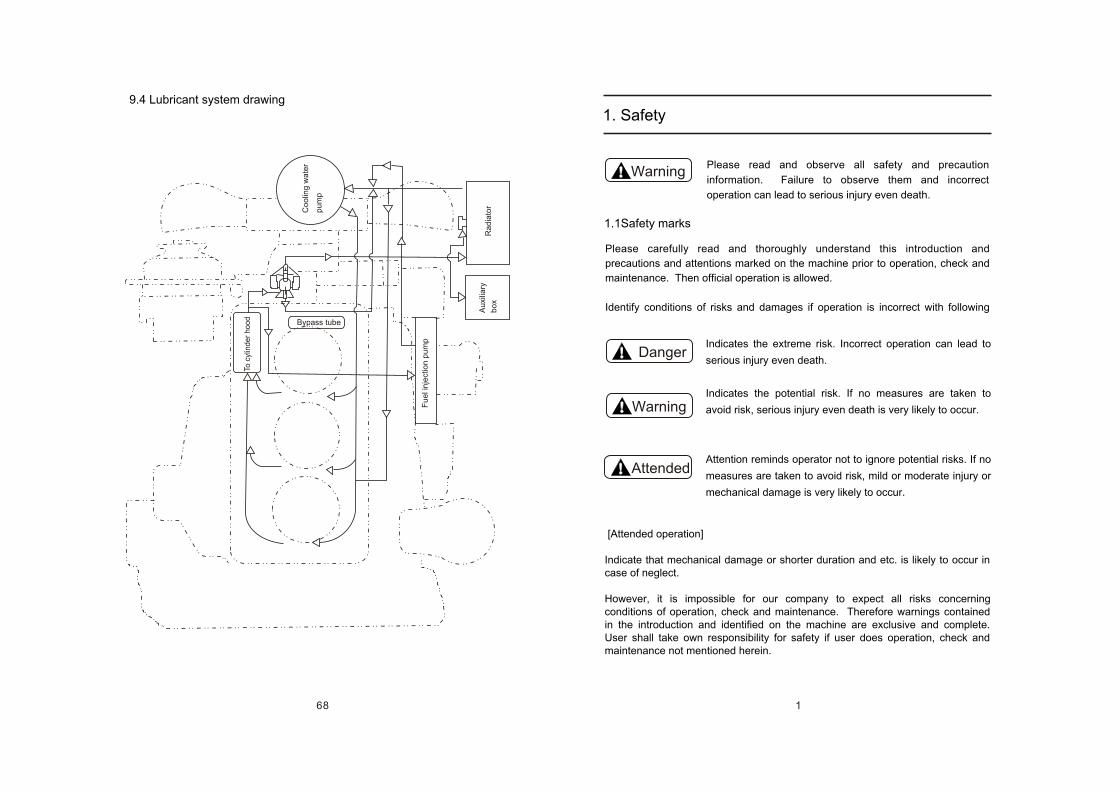
9.4 Lubricant system drawing
To c
ylin
de
r h
oo
d
Co
olin
g w
ate
r
pu
mp
Ra
dia
tor
Au
xilia
ry
bo
x
Bypass tube
Fu
el i
nje
ctio
n p
um
p
67
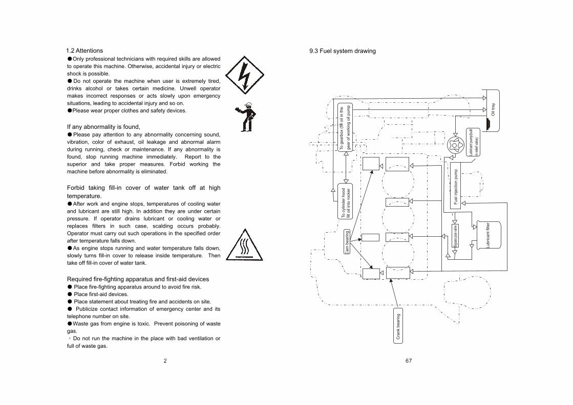
9.3 Fuel system drawing
To c
ylin
de
r h
oo
d
fill o
il in
to r
ock
er
Ca
m b
ea
rin
g
To
ge
arb
ox
(fill
oil
in th
e
ge
ar
of w
ork
ing
oil
pu
mp
Cra
nk
be
arin
g
Bypa
ss p
ipe
valve
Fu
el i
nje
ctio
n p
um
p
Lubr
ican
t pum
p(bu
ilt
in re
lief v
alve
)
Lu
brica
nt fil
ter
Oil
tra
y
2
Only professional technicians with required skills are allowed
to operate this machine. Otherwise, accidental injury or electric
shock is possible.
Do not operate the machine when user is extremely tired,
drinks alcohol or takes certain medicine. Unwell operator
makes incorrect responses or acts slowly upon emergency
situations, leading to accidental injury and so on.
Please wear proper clothes and safety devices.
If any abnormality is found,Please pay attention to any abnormality concerning sound,
vibration, color of exhaust, oil leakage and abnormal alarm
during running, check or maintenance. If any abnormality is
found, stop running machine immediately. Report to the
superior and take proper measures. Forbid working the
machine before abnormality is eliminated.
Forbid taking fill-in cover of water tank off at high
temperature.After work and engine stops, temperatures of cooling water
and lubricant are still high. In addition they are under certain
pressure. If operator drains lubricant or cooling water or
replaces filters in such case, scalding occurs probably.
Operator must carry out such operations in the specified order
after temperature falls down.
As engine stops running and water temperature falls down,
slowly turns fill-in cover to release inside temperature. Then
take off fill-in cover of water tank.
Required fire-fighting apparatus and first-aid devices Place fire-fighting apparatus around to avoid fire risk.
Place first-aid devices.
Place statement about treating fire and accidents on site.
Publicize contact information of emergency center and its
telephone number on site.
Waste gas from engine is toxic. Prevent poisoning of waste
gas.
Do not run the machine in the place with bad ventilation or
full of waste gas.
1.2 Attentions
3
Do not run the machine in the place with bad ventilation such
as room, stockroom, cabin, tunnel and enclosed box.
If it is necessary to run the machine on mentioned conditions,
necessarily extend exhaust pipe outside of room and provide
proper ventilation device to ensure sufficient ventilation.
Mount the plug screw to water outlet of exhaust muffle and
ensure no leakage of waste gas. Otherwise there is risk of
leakage of waste gas.
Electric shockTouching output terminals of running machine leads to electric
shock even death, particularly when hands are wet.
Cut off the breaker and stop running machine before wiring.
(If machine is run with shunt feeding, please cut off power
feeder outside of machine.)
Close the cover of output terminal and screw down holding
screws when machine is running.
Touching the circuit in the control panel of running machine
leads to electric shock even death. Please screw down holding
screws.
Close the breaker (OFF) and stop the machine before opening
the control panel in consideration of changeover of running
machine and other reasons.
Stop engine and take out ignition key before checking the
control panel.
Keep far away from rotating part of running machine.If operator touches part of running machine rotating at high
speed, he/ she will be injured.
Close side door of running machine carefully.
If it is necessary to open side door of running machine, keep
hand and face away from rotating part of running machine.
Stop running machine prior to check and maintenance.
Precaution of fire risk Fuel, lubricant and anti-freezing liquid are easily inflammable
materials. If they are exposed to flame or ignition source, there
is fire risk.
66
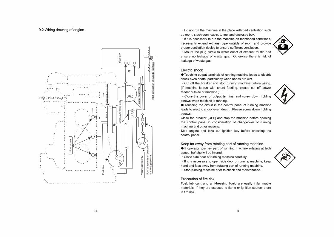
9.2 Wiring drawing of engine
Fu
el n
ozz
le
Fu
el f
ilte
r
Wa
ter
sep
era
tor
(2)
Fu
el p
um
p o
nly
fo
r o
uts
ide
fu
el t
an
k (e
lect
rica
l)
Fu
el i
nje
ctio
n p
um
p
Elec
trom
agne
tic fe
edin
g pu
mp
Fu
el t
an
k
Wa
ter
sep
era
tor
(1)
Inle
t co
nn
ect
ion
of o
uts
ide
fu
el t
an
k
4
Please stop running engine upon fuel fill-in. Additionally,
prevent cigarette or match or other ignition source close to the
machine during fuel fill-in.
Do not place inflammable materials (paper scrap or sawdust)
or hazardous materials (grease, thin liquid, powder and etc.)
near the machine.
Wipe off overflowed fuel and lubricant immediately.
Keep inflammable materials away from vent because hot
waste gas can ignite inflammable materials.
Pay attention to parts under high-temperatureHeated parts of running machine are exposed to high
temperature even when machine stops working. There is
scalding risk.
Close side door of running machine carefully.
If it is necessary to open side door of running machine, do
not touch exhaust muffle, exhaust pipe, cylinder hood, machine
body, generator casing and similar parts.
Check and maintain the machine after engine is cold
completely.
Even if machine stops working, some inside parts are still hot.
Pay special attention to operation of storage batteryStorage battery can produce inflammable gas. So incorrect
operations can lead to explosion or serious injury.
Do charging in the well-ventilated place. Otherwise it is
exposed to ignition and explosion risks due to inflammable gas.
Do not connect (+) and (-) poles of storage battery upon lead
connection. Additionally do not connect wrong leads. Splashed
spark may ignite inflammable gases from storage battery thus
to cause explosion.
Electrolyte of storage battery contains thin sulfuric acid.
Incorrect operation can lead to serious injury.
If clothes or skin touches electrolyte of storage battery,
immediately wash with plenty of water. If eyes touch electrolyte
of storage battery, immediately wash with plenty of water and
consult physician.
If electrolyte of storage battery is below LOWER LEVEL, do
not use storage battery. Inside aging of storage battery leads to
shorter life even explosion.
65
Re
d 2
0#
yello
w &
gre
en
20
#
Red
& W
hite
20#
Yel
low
& W
hite
20#
DC
cha
rgin
g ou
tput
Civic
-electri
city
input
Yello
w 12
#
Gre
en 1
2#
Red
12#
Blac
k 12
#
Red
18#
Green1
8#Blu
e 18#
Blue 1
8#
Yellow
20#
Yellow
12#
Green
12#
Red 1
2#
Black
12#
Blu
e &
Whi
te 2
0#
AC
cha
rgin
g in
put
Red
20#
Bla
ck 2
0#
Yello
w 12
#
Gre
en 1
2#
Red
12#
Blac
k 12
#
Yello
w 12
#
Gre
en 1
2#
Red
12#
Blac
k 12
#
Yellow
& Gre
en 12#
Civ
ic-e
lect
ricity
A
C i
nput C
ontr
ol
mod
ule
Gen
erat
or A
Csi
gnal
inpu
t
Brow
n &
Blue
20#
Ye
llow
&
B
lue
20
#KM
1
Oran
ge &
Bl
ue 2
0#
Pin
k &
B
lue
20
#
Pu
rple
&
Gra
y 2
0#
Purp
le &
Bla
ck 2
0#
Civic
-elec
tricit
y su
pply
outp
ut
Gen
erat
or
supp
ly o
utpu
t
Cont
rol
signa
l
Yello
w 12
#
Gre
en 1
2#
Red
12#
Blac
k 12
#
Yello
w 0.
5G
reen
Re
d Bl
ack
0.5
0.5 0.
5
Red
& B
lack
20#
Gre
en &
Bla
ck 2
0#
Yel
low
& B
lack
20#
Pur
ple
20#
Gre
en 1
8#
Red
18#
White
18#
Red
18#
Red 1
4#K
1Gr
een 1
4# Gree
n 20#
Whit
e18#
Blue
18#
Ora
nge
18#
Red &
Blue
20#
Green&
Blue2
0#
Gary
& B
lue20
#
Blac
k & B
lue20
#Blu
e 18#
Blue 1
8#
Adjus
ter
Yellow
16#
Blue 1
0#
Yellow
10#
Brown
18#
Batter
y
Yellow
& Gre
en18# Pu
rple &
Orange
18#
Starting
electro
motor
Starting
magne
t
Red
10#
Pink
20#
Gray
18#
Gray &
White 2
0#
Ora
nge
18#
Abno
rmal
sig
nal in
put
Runn
ing
signa
l out
put
Intelli
gent
pane
l con
troller
Intellig
ent pa
nel
displa
y
Startin
g sign
al inpu
tBr
own 2
0#
Reheat
ing sign
al outp
ut
Startin
g signa
l outpu
t
over lo
ading si
gnal ou
tput
Whit
e20#
ATS
optio
ns
On/
off r
elat
ion
shee
t of s
witc
h lo
ck:
Volta
ge s
ampl
ing
Cur
rent
sam
plin
g
Water
temp
eratur
e sw
itch
Low
oilpre
ssure
sw
itch
Flyw
heel
AC
Volta
ge sa
mpli
ng
Blac
k 20
#sh
unt t
rip
Gree
n & Bl
ue 2
0#
26
25
24
23
22
21
20
19
18
17
16
15
14
13
12
11 10 9 8 7 6 5 4 3 2 1 No
SA
1
M1
M2
SA
TC
GB
L1
L2
L3
W3
W2
W1
U,V
,W,N
,E
SB
B2
011
C
B2
011
C
Fu
1
YV
KM
1,K
M2
K3
K1
,K2
,K4
QF
Co
de
SQ1
SQ2
SQ3
AVR
(Inte
lligen
ce)
FU2
FU3
FU4
Fu
el f
ee
d p
um
p
Le
ve
l co
ntr
olle
r
Ign
itio
n s
witch
Tra
nsfo
rme
r
Ch
arg
ing
re
gu
lato
r
Sto
rag
e b
atte
ry
AV
R
Exc
itatio
n w
ind
ing
Sh
ee
t fu
se
lin
k
Sh
ee
t fu
se
lin
k
4-w
ay c
ut-
ou
t b
ox
Fu
se
(6
x3
0)
10
A
AC
co
nta
cto
r
DC
co
nta
cto
r
Re
lay
AT
S m
od
ule
Inte
llig
en
t sc
ree
n
Inte
llig
en
t m
od
ule
Bre
ake
r
Na
me
Selec
tion s
witch
of fu
el fee
d pum
p
Curre
nt m
utua
l-ind
icato
r
3-ph
ase
outp
ut b
oard
Emer
genc
y st
op b
utto
n
Wind
ing of
char
ging g
ener
ator
Windin
g of po
wer ge
neratio
n and
samplin
g
Thro
ttle
elec
trom
agne
t
1 1 1 1 1 1 1 1 3 2 1 1 2 1 2 1 2 1 1 1 1 Qty
.
3S
S3
-10
B
DC
12
V
Jk4
27
35
Ah
50
/5m
A
HV
W4
11E
R
10
A
20
A
B2
04
1C
B2
01
C
A2
6-4
0-0
0
PLY
-MB
-D
Ma
teria
l
220V
/15V
40A
6-QW-
36 12
V 36A
h 310
A
PLY-
DAV
R-9
5S
QDC-
100A
DC1
2V
HFV4
12V
20A
PLY-
MB-
ATS-
S1
PLY-
MB-
ATS-
C
B0-1
00EB
3P/
16A
Rem
ark
ABB
BeiYu el
ectric
5
Prohibit lifting the machine with non-designated
hook.Do not lift the machine at non-designated positions
because of insufficient lifting strength. Otherwise falling
machine leads to mechanical damage or human injury.
Upon lifting the machine, please use the designated
metal hook in the center of top cover.
Do not stand under lifted machine.
Do not lift the machine when engine starts or runs.
Pay attention to overlapping-storageIncorrect overlapping-storage may cause overturn of
machines and mechanical damage.
Place the machine on the flat and solid ground. Keep
machines level. Ensure that ground can bear overlapping
weight.
Two layers of overlapping storage are allowed. Machines
on the upper layer must be smaller and lighter than this
machine.
Check if machine bolts are loose or missing.
Separate machines with wooden lumps. Keep all
wooden lumps bearing same weight.
Do not move overlapped machines. Otherwise it may
cause overturn and falling.
Maintenance attentionsMeaning of warning labels for check and maintenance
During check and maintenance, serious accident even
death may occur if unnecessary persons start the engine
or operate speed-regulating lever.
Identify the warning label [Danger Not run!] at obvious
positions such starter in order to avoid unnecessary
persons carry out unintended operation upon check and
maintenance.
Check and maintenance after engine stops.Start check and maintenance after engine stops.
If maintenance requires running engine, such
maintenance must be done by two persons. One person is
responsible for maintenance while the other person is
ready for stopping running engine at any time.
Maintenance operator shall take precautions against
body and clothes into rotation parts of machine.
Danger
Not run
64
Red
18#
Green1
8#Blu
e 18#
Blue 1
8#
Yellow
20#
Yellow
20#
Red
20
#ye
llow
& g
ree
n 2
0#
Oran
ge &
Whit
e 20
#
Red
& W
hite
20#
DC
cha
rgin
g ou
tput
Blu
e &
Whi
te 2
0#
Red
20#
Bla
ck 2
0#
Civ
ic-e
lect
ricity
A
C i
nput
A
TS
Con
trol
m
odul
e
Gen
erat
or A
Csi
gnal
inpu
t
Brow
n &
Blue
20#
Ye
llow
&
B
lue
20
#
Oran
ge &
Bl
ue 2
0#
Pin
k &
B
lue
20
#
Pu
rple
&
Gra
y 2
0#
Purp
le &
Bla
ck 2
0#
Civic
-elec
tricit
y su
pply
outp
ut
Gen
erat
or
supp
ly o
utpu
t
Cont
rol
signa
l
Intelli
gent
pane
l con
troller
Intellig
ent pa
nel
displa
y
Startin
g sign
al inpu
t
Red
& W
hite
20#
Yello
w &
Whi
te 2
0#A
C c
harg
ing
inpu
t
Civi
c-elec
tricity
inp
ut ~
Pur
ple
20#
Gre
en 1
8#
Red
18#
White
18#
Red
18#
Red 1
4#Gr
een 1
4# Gree
n 20#
Whit
e18#
Blue
18#
Ora
nge
18#
Red &
Blue
20#
Green&
Blue2
0#
Gary
& B
lue20
#
Blac
k & B
lue20
#
Blue 1
8#
Blue 1
8#
Adjus
ter
Yellow
16#
Blue 1
0#
Yellow
10#
Brown
18#
Batter
y
Yellow
& Gre
en18# Pu
rple &
Orange
18#
Starting
electro
motor
Starting
magne
t
Red
10#
Pink
20#
Gray
18#
Gray &
White 2
0#
Ora
nge
18#
Abno
rmal
sig
nal in
put
Runn
ing
signa
l out
put
Brow
n 20#
Reheat
ing sign
al outp
ut
Startin
g signa
l outpu
t
over lo
ading si
gnal ou
tput
Whit
e20#
Red
20#
Bla
ck 2
0#
Gar
y 20
#
Gra
y 2
0#
Bla
ck 1
2#
Red
12#
Blac
k 12
#Bl
ack
8#Red
12#
Red
8#
Bla
ck 2
0#
Red
& B
lue2
0#
Red
8#
Bla
ck 8
#
Red
8#
Bla
ck 8
#Bla
ck 8#
Red
8#
Red
8#
Blac
k 8#
Bla
ck &
Whi
te 2
0#AT
S op
tions
On/
off r
elat
ion
shee
t of s
witc
h lo
ck:
Volta
ge s
ampl
ing
Cur
rent
sam
plin
g
Water
temp
eratur
e sw
itch
Low
oilpre
ssure
sw
itch
Flyw
heel
AC
Volta
ge sa
mpli
ng
shun
t trip
Yello
w &
Gre
en 1
2#
26
25
24
23
22
21
20
19
18
17
16
15
14
13
12
11 10 9 8 7 6 5 4 3 2 1 No
SA
1
M1
M2
SA
TC
GB
L1
W3
W2
W1
U,N
,E
SB
B2
011
C
B2
011
C
Fu
1
YV
KM
1,K
M2
K3
K1
,K2
,K4
QF
Co
de
SQ1
SQ2
SQ3
AVR
(Inte
lligen
ce)
FU2
FU3
FU4
Fu
el f
ee
d p
um
p
Le
ve
l co
ntr
olle
r
Ign
itio
n s
witch
Tra
nsfo
rme
r
Ch
arg
ing
re
gu
lato
r
Sto
rag
e b
atte
ry
AV
R
Exc
itatio
n w
ind
ing
Sh
ee
t fu
se
lin
k
Sh
ee
t fu
se
lin
k
4-w
ay c
ut-
ou
t b
ox
Fu
se(
6x3
0)
10
A
AC
co
nta
cto
r
DC
co
nta
cto
r
Re
lay
AT
S m
od
ule
Inte
llig
en
t sc
ree
n
Inte
llig
en
t m
od
ule
Bre
ake
r
Na
me
Selec
tion s
witch
of fu
el fee
d pum
p
Cur
rent
mut
ual-i
ndic
ator
3-ph
ase
outp
ut b
oard
Emer
genc
y st
op b
utto
n
Wind
ing of
char
ging g
ener
ator
Windin
g of po
wer ge
neratio
n and
samplin
g
Thro
ttle
elec
trom
agne
t
1 1 1 1 1 1 1 1 1 2 1 1 3 1 2 1 2 1 2 1 1 1 1 Qty
.
3S
S3
-10
B
DC
12
V
Jk4
27
QC
D-3
5A
h
50
/5m
A
HV
W4
11E
R
10
A
20
A
B2
04
1C
B2
01
C
A2
6-4
0-0
0
PLY
-MB
-D1
Ma
teria
l
220V
/15V
40A
6-QW-
36 12
V 36A
h 310
A
PLY-
DAV
R-9
5S
QDC-
100A
DC1
2V
HFV4
12V
20A
PLY-
MB-
ATS-
S1
PLY-
MB-
ATS-
C1
B0-1
00EB
2P/
50A
Rem
ark
ABB
BeiYu el
ectric
6
Pay attention to electric shockSome parts of running machine are under high voltage. It is
dangerous.
Start check and maintenance after engine stops.
Pay attention to parts at high-temperatureAs certain parts in the machine are hot
It is necessary to start check and maintenance after engine
stops.
Please pay particular attentions. Even if machine stops
working, some inside parts are still hot. Therefore check and
maintain the machine after engine is cold completely.
Attentions for handling storage batteryIncorrect operation may lead to explosion even serious injury.
Take out the earth line of storage battery (-) pole then cut off
power supply upon mechanical check and maintenance.
Connect (+) pole prior to (-) pole upon connection of storage
battery.
Lighting apparatus must have explosion-proof.
Please use lighting apparatus with explosion-proof upon
check of fuel, lubricant, cooling water and electrolyte of storage
battery. Otherwise, explosion may occur.
Periodical change of important parts
Periodically change following parts because aging or
damage may cause fire accident.
Fuel system: Periodically change fuel hose, fuel pipe, cover
of fuel tank and others even if no abnormalities.
Disposal of waste oil and water
Do not dispose waste oil into sewage or river, which pollutes
environment.
Collect the lubricant drained out from the machine in the
special container. Do not dispose it on the ground.
Disposal of fuel, lubricant, cooling water, solvent, filters,
storage battery and other hazardous matters shall observe
state and local regulations.
63
Re
d 2
0#
yello
w &
gre
en
20
#
Bla
ck &
Whi
te 2
0#
DC
cha
rgin
g ou
tput
Blu
e &
Wh
ite
20
#
AC
ch
arg
ing
inp
ut
Red
20#
Bla
ck 2
0#C
ivic
-ele
ctric
ity
AC
inp
ut
Brow
n &
Blue
20#
Ye
llow
&
B
lue
20
#
Oran
ge &
Bl
ue 2
0#
Pin
k &
B
lue
20
#
Pu
rple
&
Gra
y 2
0#
Purp
le &
B
lack
20#
Civic-
electr
icity s
upply
outpu
t
Gene
rator
supp
ly ou
tput
Cont
rol
signa
l
Pur
ple
20# G
reen
18#
Red
18#
White
18#
Red
18#
Red 1
4#Gr
een 1
4# Gree
n 20#
Whit
e18#
Blue
18#
Ora
nge
18#
Red &
Blue
20#
Green&
Blue2
0#
Gary
& B
lue20
#
Blac
k & B
lue20
#
Blue 1
8#
Blue 1
8#
Adjus
ter
Yellow
16#
Blue 1
0#
Yellow
10#
Brown
18#
Batter
y
Yellow
& Gre
en18# Pu
rple &
Orange
18#
Starting
electro
motor
Starting
magne
t
Red
10#
Pink
20#
Gray
18#
Gray &
White 2
0#
Ora
nge
18#
Abno
rmal
sig
nal in
put
Runn
ing
signa
l out
put
Intelli
gent
pane
l con
troller
Intellig
ent pa
nel
displa
y
Startin
g sign
al inpu
tBr
own 2
0#
Reheat
ing sign
al outp
ut
Startin
g signa
l outpu
t
over lo
ading si
gnal ou
tput
Whit
e20#
Red
& W
hite
20#
Bla
ck &
Whi
te 2
0#
Gen
erat
or A
Csi
gnal
inpu
t
Con
trol
m
odul
eR
ed &
Whi
te 2
0#
Red
8#
Bla
ck 8
#
Red
8#
Bla
ck 8
#G
reen
& B
lue
20#
Bla
ck 2
0#
Red
8#
Red
8# R
ed 1
2#R
ed 1
2#
Blu
e 12
#B
lue
8#
Brow
n12#
Blac
k 8#
Bla
ck 1
2#
Yellow& Green 12# Blac
k 10#
Brow
n 8#
Blu
e 8#
Brow
n 8#
Red
8#
Blac
k 8#
Yello
w 20
#
Red
18#
Green
18#
Blu
e 18
#
Blu
e 18
#
Yello
w 20
#
Bla
ck 8
#
Ye
llo
w &
Gre
en 1
2#
Red
& B
lue
20#
Blue
& W
hite
20#
Brow
n &
Whi
te 2
0#
Blue
& B
lack
20#
Brow
n &
Blac
k 20
#
On/
off r
elat
ion
shee
t of s
witc
h lo
ck:
Volta
ge s
ampl
ing
Cur
rent
sam
plin
g
Water
temp
eratur
e sw
itch
Low
oilpre
ssure
sw
itch
Flyw
heel
AC
Volta
ge sa
mpli
ng
shun
t trip
ATS
optio
ns
C
ivic
-ele
ctrici
ty
inp
ut ~
24
0V
Ora
nge
& W
hite
20#
28
27
26
25
24
23
22
21
20
19
18
17
16
15
14
13
12
11 10 9 8 7 6 5 4 3 2 1 No
SA
1
M1
M2
SA
TC
GB
L1
L2
W4
W3
W1
W2
U,N
,E
SB
B2
011
C
B2
011
C
Fu
1
YV
KM
1,K
M2
K3
K1
,K2
,K4
QF
Co
de
SQ1
SQ2
SQ3
AVR
(Inte
lligen
ce)
FU2
FU3
FU4
So
cke
t
Fu
el fe
ed
pu
mp
Le
vel co
ntr
olle
r
Ign
itio
n s
witch
Tra
nsfo
rme
r
Ch
arg
ing
re
gu
lato
r
Sto
rag
e b
atte
ry
AV
R
Exci
tatio
n w
ind
ing
Sh
ee
t fu
se
lin
k
Sh
ee
t fu
se
lin
k
4-w
ay
cut-
ou
t b
ox
Fu
se
(6
x30
) 1
0A
AC
co
nta
cto
r
DC
co
nta
cto
r
Re
lay
AT
S m
od
ule
Inte
llig
en
t scr
ee
n
Inte
llig
en
t m
od
ule
Bre
ake
r
Na
me
Selec
tion s
witch
of fu
el fee
d pum
p
Curre
nt m
utua
l-ind
icato
r
Doub
le-v
olta
ge o
utpu
t boa
rd
Emer
genc
y st
op b
utto
n
Wind
ing of
char
ging g
ener
ator
Windin
g of po
wer ge
neratio
n and
samplin
g
Thro
ttle
elec
trom
agne
t
3 1 2 1 1 1 1 1 1 2 2 1 1 3 1 2 1 2 1 2 1 1 1 1 Qty
.
25
0V
26
A
3S
S3
-10
B
DC
12
V
Jk4
27
QC
D-3
5A
h
50
/5m
A
HV
W4
11E
R
10
A
20
A
B2
04
1C
B2
01
C
A2
6-4
0-0
0
PLY
-MB
-D2
Ma
teria
l
220V
/15V
40A
h
6-QW-
36 12
V 36A
h 310
A
PLY-
DAV
R-9
5S
QDC-
100A
DC1
2V
HFV4
12V
20A
PLY-
MB-
ATS-
S2
PLY-
MB-
ATS-
C2
B0-1
00EB
2P/
50A
Rem
ark
ABB
BeiYu el
ectric
X1
X2
X3
9.1 Wiring drawing of generator
9. Electrical wiring drawing
7
1.3 Warning labels
Several warning identifications are marked on the machine for safety concern.
Keep identifications clean regularly. Prevent them from contamination or damage.
In case of contamination or damage, replace it with new one.
1) Labeling
NO.
1
2
3
4
5
NO.
6
7
8
9
10
Meaning
Pay attention to high temperature
Forbid lifting the machine
Lifting position
Prevent flame and fire
Pay attention to exhaust and scalding
Pay attention to electric shock and connect earth line
Meaning
Attended operations
Pay attention to handling of storage battery
Avoid being involved in the running machine
Attentions for inside check of engine
62
P-08
P-01
P-02
P-03
P-04
P-05
P-06
P-07
Check excitation line and carbon brush
Replace AVR or motor in same type
Replace fuse in same type
Check circuit and inserts
Replace start motor
No signal input of successful start
Check fuel supply system and fuel pump
Replace emergency stop button
Replace charging motor in the same type
Error Analysis Solutions
No start display
3.Open-circuit of excitation circuit
4.Burnt AVR or motor
1.
1.Broken fuse of start circuit
2.
3.Damage of start motor
4.Damage of charging motor
5.Error of fuel system
1.
1.Open-circuit of charging circuit
2.Error of charging motor
1.High-temperature of cooling
water.
2.Insufficient cooling water
3.
4.
1.Broken panel fuses
2.
3.Bad contact of inserts
1.Insufficient lubricant
2.Error of lubrication system
3.
4.
1.Broken sampling harness
Bad contact or damage of switch lock
Damage of low-oil-pressure switch (normal open)
Earth short-circuit of low-oil-pressure switch
2.Abnormal frequency (excessive or below)
3. Abnormal fuel system; instable rotation speed of engine
1.Broken sampling harness
2.Abnormal voltage (excessive or below)
Earth short-circuit of water temperature switch
Damage of water temperature switch (normal open)
Damage of emergency stop button or short-circuit of normal open point
OverloadReduce load till load is below rated value.
Broken wire of start circuit or bad contact of inserts
Replace fuses
Fill lubricant to rated value
Check lubrication system
Replace with same type
Check circuit
Check output frequency with AVO meter; calibrate actual value as per displayed value; adjust rotation speed of engine; keep output frequency compliant with ex-works setting
Check voltage sampling harness if not indicate voltage or frequency after machine starts
Check or replace switch lock it according to on-off relation of switch lock
Check module nine PIN inserts and data line
Check fuel system
Check voltage sampling harness if not indicate voltage or frequency after machine starts
Check output frequency with AVO meter; calibrate actual value as per displayed value; adjust AVR to ensure output voltagecompliant with rated value
Add cooling water to rated level
Check circuit
Cut off breaker; idle machine for certaintime; stop machine and re-start it after water temperature falls down.
Reduce load till load is below rated value. Then close breaker.
Check signal of AC charging generator and inserts
Replace water temperature switch in the same type
8
c. Forbid lifting the machine.
Falling danagerForbid lifting
d. Attended operations.
Danger
(2) Warning label (identification)
a. Pay attention to exhaust and scalding. b. Lifting positions
Use the proper device in the room and other places with bad ventilation because of hazardous waste gas.
Pay attention to exhaust
Attention Attention
Pay attention to scalding
Touching hot parts may cause scalding risk.
Carefully read and thoroughly understand this introduction prior to use.
If this introduction or safety identification is damaged, please order one from
KIPOR sales department.
Forbid connecting the machine with distribution line of power company and
distribution line in the building willfully.
Stop the engine before fuel fill-in.
Check if breaker is cut off before machine starts.
Forbid moving running machine.
Use the machine after its wheels are fixed.
Only professional technicians with required skills are allowed to operate this
machine for safety concern.
There is risk of electric shock and injury.
Some parts in the machine are under high voltage, rotation and high temperature.
Close side door before machine starts.
Parts in the cover of output terminal and control panel are under high voltage.
Close side door before machine starts.
Stop running machine prior to check and maintenance.
Lifting position
Attention
Attention
61
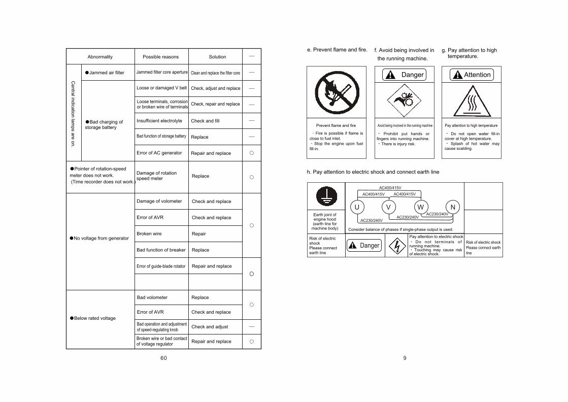
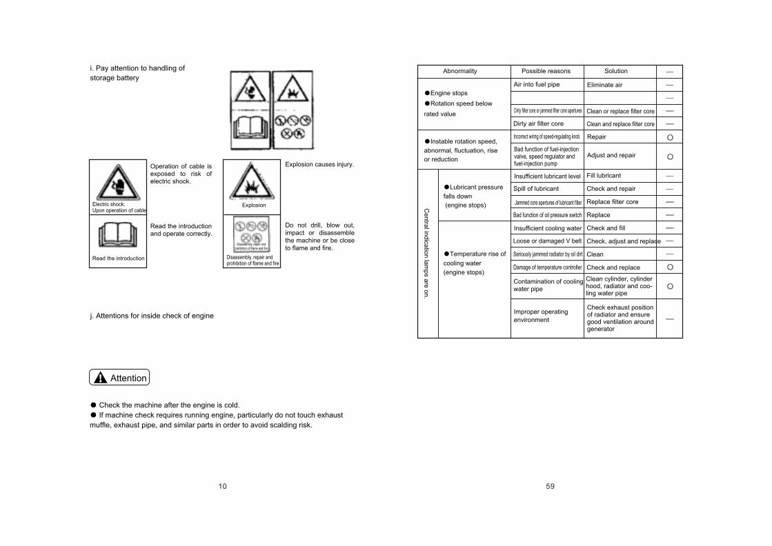
Abnormality Possible reasons Solution
Check and replace
Check, adjust and repair
Check and replace
Check and replace
Check and replace
Reduce load
Error of AVR
Error of AVR
Imbalance load
Bad function of field circuit
Bad adjustment of speed-regulating knob
Bad function of voltage regulator
High-temperature of generator due to overload
Adjust load to balance load at 3 phases
Cannot turn single-phase breaker to ON
Excessive voltage
Voltage falls down considerably withincrease of load
Cannot adjust voltage
Pointer of current meter does not work with load.
Pointer of freque-ncy meter does not work.
Cannot turn 3-phasebreaker to ON
Replace
Replace
Check and repair
Re-operate
Error of frequency meter
Bad breaker
Short-circuit of load circuit
Replace;
connect with U-phase
terminal
Replace
Check and replace
Error of current meter or
CT; use terminals not at
U phase
Bad breaker
Short-circuit of load circuit
Improperly release of cutoff
and electricity leakage alarm
9
AttentionDanger
Danger
U V W N
AC400/415V
AC400/415V AC400/415V
AC230/240VAC230/240V
AC230/240V
h. Pay attention to electric shock and connect earth line
e. Prevent flame and fire.
Fire is possible if flame is
close to fuel inlet.
Stop the engine upon fuel
fill-in.
f. Avoid being involved in
the running machine.
g. Pay attention to high temperature.
Prohibit put hands or fingers into running machine.
There is injury risk.
Do not open water fill-in cover at high temperature.
Splash of hot water may cause scalding.
Avoid being involved in the running machine Pay attention to high temperaturePrevent flame and fire
Earth joint of engine hood(earth line for
machine body)
Risk of electric shockPlease connectearth line
Consider balance of phases if single-phase output is used.
Risk of electric shock
Please connect earth
line
Do not terminals of running machine.
Touching may cause risk of electric shock.
Pay attention to electric shock
60
Jammed air filter
Bad charging of storage battery
Abnormality Possible reasons Solution
Ce
ntra
l ind
icatio
n la
mp
s are
on
.
Damage of rotationspeed meter
Check and fill
Replace
Repair and replace
Check and replace
Check and replace
Repair
Replace
Repair and replace
Damage of volometer
Error of AVR
Broken wire
Bad function of breaker
Jammed filter core aperture
Loose or damaged V belt
Loose terminals, corrosion or broken wire of terminals
Insufficient electrolyte
Bad function of storage battery
Error of AC generator
Check, adjust and replace
Check, repair and replace
Replace
Clean and replace the filter core
Bad volometer
Error of AVR
Bad operation and adjustment of speed-regulating knob
Broken wire or bad contact of voltage regulator
Replace
Check and replace
Check and adjust
Repair and replace
Error of guide-blade rotator
No voltage from generator
Pointer of rotation-speed
meter does not work.
(Time recorder does not work.)
Below rated voltage
10
Attention
i. Pay attention to handling of
storage battery
Operation of cable is exposed to risk of electric shock.
Read the introduction and operate correctly.
Explosion causes injury.
Do not drill, blow out, impact or disassemble the machine or be close to flame and fire.
Electric shock: Upon operation of cable
Explosion
Read the introduction Disassembly, repair andprohibition of flame and fire
Disassembly, repair andprohibition of flame and fire
j. Attentions for inside check of engine
Check the machine after the engine is cold.
If machine check requires running engine, particularly do not touch exhaust
muffle, exhaust pipe, and similar parts in order to avoid scalding risk.
59
Engine stops
Rotation speed below
rated value
Instable rotation speed,
abnormal, fluctuation, rise
or reduction
Lubricant pressure
falls down
(engine stops)
Temperature rise of
cooling water
(engine stops)
Abnormality Possible reasons Solution
Ce
ntra
l ind
icatio
n la
mp
s are
on
.
Air into fuel pipe
Dirty filter core or jammed filter core apertures
Dirty air filter core
Incorrect wiring of speed-regulating knob
Bad function of fuel-injectionvalve, speed regulator andfuel-injection pump
Eliminate air
Clean or replace filter core
Clean and replace filter core
Insufficient lubricant level
Spill of lubricant
Jammed core apertures of lubricant filter
Bad function of oil pressure switch
Repair
Adjust and repair
Fill lubricant
Check and repair
Replace filter core
Replace
Check and fill
Check, adjust and replace
Clean
Check and replace
Clean cylinder, cylinder hood, radiator and coo-ling water pipe
Check exhaust positionof radiator and ensure good ventilation around generator
Insufficient cooling water
Improper operating
environment
Contamination of coolingwater pipe
Damage of temperature controller
Seriously jammed radiator by oil dirt
Loose or damaged V belt
11
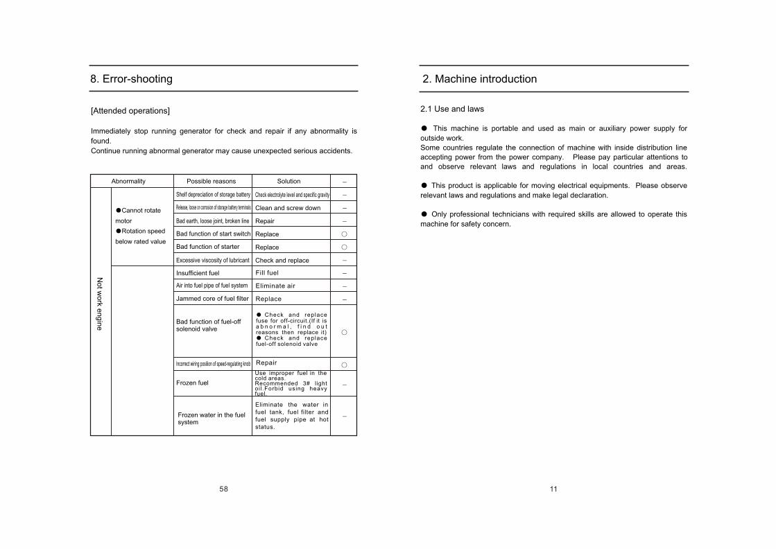
2. Machine introduction
2.1 Use and laws
This machine is portable and used as main or auxiliary power supply for
outside work.
Some countries regulate the connection of machine with inside distribution line
accepting power from the power company. Please pay particular attentions to
and observe relevant laws and regulations in local countries and areas.
This product is applicable for moving electrical equipments. Please observe
relevant laws and regulations and make legal declaration.
Only professional technicians with required skills are allowed to operate this
machine for safety concern.
58
[Attended operations]
Immediately stop running generator for check and repair if any abnormality is
found.
Continue running abnormal generator may cause unexpected serious accidents.
8. Error-shooting
Abnormality Possible reasons Solution
Cannot rotate
motor
Rotation speed
below rated value
No
t wo
rk en
gin
e
Bad function of starter
Excessive viscosity of lubricant
Bad function of start switch
Bad earth, loose joint, broken line
Release, loose or corrosion of storage battery terminals
Shelf depreciation of storage battery
Insufficient fuel
Air into fuel pipe of fuel system
Jammed core of fuel filter
Bad function of fuel-off solenoid valve
Incorrect wiring position of speed-regulating knob
Frozen fuel
Frozen water in the fuel system
Clean and screw down
Repair
Replace
Replace
Check and replace
Check electrolyte level and specific gravity
Fill fuel
Eliminate air
Replace
Check and replace fuse for off-circuit.(If it is a b n o r m a l , f i n d o u t reasons then replace it)
Check and replace fuel-off solenoid valve
Use improper fuel in the cold areas.Recommended 3# light oi l .Forbid using heavy fuel.
Repair
Eliminate the water in fuel tank, fuel filter and fuel supply pipe at hot status.
12
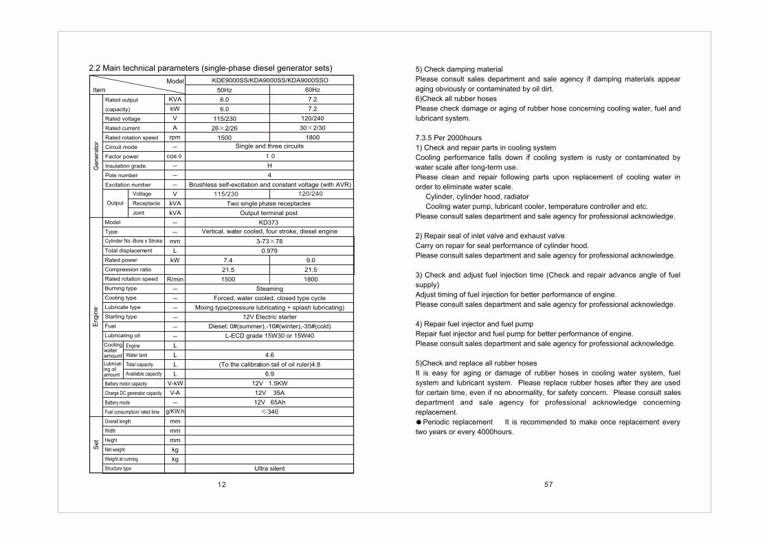
Rated output
(capacity)
Rated voltage
Rated current
Rated rotation speed
Circuit mode
Factor power
Insulation grade
Pole number
Excitation number
Model
Type
Total displacement
Rated power
Compression ratio
Rated rotation speed
Burning type
Cooling type
Lubricate type
Starting type
Fuel
Lubricating oil
Battery motor capacity
Charge DC generator capacity
Battery mode
Fuel consumption/ rated time
Overall length
Width
Height
Net weight
Weight at running
Structure type
KVA
kW
V
A
rpm
--
cos
--
--
--
V
kVA
kVA
--
--
mm
L
kW
R/min
--
--
--
--
--
--
L
L
L
L
V-kW
V-A
--
mm
mm
mm
kg
kg
g/KW.h
KDE9000SS/KDA9000SS/KDA9000SSO
50Hz
6.0
6.0
115/230
26 2/26
1500
60Hz
7.2
7.2
120/240
30 2/30
1800
1.0
H
4
Brushless self-excitation and constant voltage (with AVR)
115/230 120/240
Two single phase receptacles
Output terminal post
KD373
Vertical, water cooled, four stroke, diesel engine
3-73 78
0.979
7.4
21.5
1500
9.0
21.5
1800
Steaming
Forced, water cooled, closed type cycle
Mixing type(pressure lubricating + splash lubricating)
12V Electric starter
Diesel: 0#(summer),-10#(winter),-35#(cold)
L-ECD grade 15W30 or 15W40
4.6
(To the calibration tail of oil ruler)4.8
6.9
12V 1.5KW
12V 35A
12V 65Ah
340
Ultra silent
Single and three circuits
Model
ItemG
en
era
tor
Voltage
Receptacle
Joint
Output
Cylinder No.-Bore x Stroke
En
gin
eS
et
Engine
Water tank
Total capacity
Available capacity
Coolingwateramount
Lubricat-ing oilamount
2.2 Main technical parameters (single-phase diesel generator sets)
57
5) Check damping material
Please consult sales department and sale agency if damping materials appear
aging obviously or contaminated by oil dirt.
6)Check all rubber hoses
Please check damage or aging of rubber hose concerning cooling water, fuel and
lubricant system.
7.3.5 Per 2000hours
1) Check and repair parts in cooling system
Cooling performance falls down if cooling system is rusty or contaminated by
water scale after long-term use.
Please clean and repair following parts upon replacement of cooling water in
order to eliminate water scale.
Cylinder, cylinder hood, radiator
Cooling water pump, lubricant cooler, temperature controller and etc.
Please consult sales department and sale agency for professional acknowledge.
2) Repair seal of inlet valve and exhaust valve
Carry on repair for seal performance of cylinder hood.
Please consult sales department and sale agency for professional acknowledge.
3) Check and adjust fuel injection time (Check and repair advance angle of fuel
supply)
Adjust timing of fuel injection for better performance of engine.
Please consult sales department and sale agency for professional acknowledge.
4) Repair fuel injector and fuel pump
Repair fuel injector and fuel pump for better performance of engine.
Please consult sales department and sale agency for professional acknowledge.
5)Check and replace all rubber hoses
It is easy for aging or damage of rubber hoses in cooling water system, fuel
system and lubricant system. Please replace rubber hoses after they are used
for certain time, even if no abnormality, for safety concern. Please consult sales
department and sale agency for professional acknowledge concerning
replacement.
Periodic replacement It is recommended to make once replacement every
two years or every 4000hours.
13
KVA
kW
V
A
rpm
--
cos
--
--
--
V
kVA
kVA
--
--
mm
L
kW
R/min
--
--
--
--
--
L
--
L
L
L
L
V-K W
V-A
--
mm
mm
mm
kg
kg
KDE11SS/KDA11SS/KDA11SSO KDE13SS/KDA13SS/KDA13SSO
50Hz
8.5
8.5
115/230
37 2/37
1500
60Hz
10.5
10.5
120/240
43.8 2/43.8
1800
50Hz
10
10
115/230
43.5 2/43.5
1500
60Hz
12
12
115/230
50 2/50
1800
1.01.0
H
4
Brushless self-excitation and constant voltage( with AVR)
115/230 120/240 115/230 120/240
Two single phase receptacles
Output terminal post
KD388G
Vertical, water cooled, four stroke, diesel engine
3-88 90
1.642
3-88 90
1.642
12.3
18.2
1500
14.8
18.2
1800
12.3
18.2
1500
14.8
18.2
1800
Direct injection
Forced, water cooled, closed type cycle
Mixing type(pressure lubricating + splash lubricating)
12V Electric starter
Diesel: 0#(summer),-10#(winter),-35#(cold)
65
L-ECD grade 15W30 or 15W40
2
g/KW.h
2.6
6.9
3.3
12V 1.4KW
12V 15A
12V 80Ah
340
1570
780
1050
675
750
685
760
Rated output
(capacity)
Rated voltage
Rated current
Rated rotation speed
Circuit mode
Factor power
Insulation grade
Pole number
Excitation number
Model
Type
Total displacement
Rated power
Compression ratio
Rated rotation speed
Burning type
Cooling type
Lubricate type
Starting type
Fuel
Fuel tank capacity
Lubricating oil
Battery motor capacity
Charge DC generator capacity
Battery mode
Fuel consumption/ rated time
Overall length
Width
Height
Net weight
Weight at running
Structure type
Model
Item
Ge
ne
rato
r
Voltage
Receptacle
Joint
Output
En
gin
eS
et
Engine
Water tank
Total capacity
Available capacity
Coolingwateramount
Lubricat-ing oilamount
Single and three circuits Single and three circuits
Two single phase receptacles
Output terminal post
KD388G
Ultra silent
56
Attention
Drainage plug of cooling water
Cover of water inlet7.3.4 Per 1000hours
1) Replace cooling water
Performance of cooling water may fall down if it is
contaminated by rust or dirt.
Replace the additive of anti-freezing liquid
periodically as it turns aging.
Replace cooling water once per year.
Do not drain off water immediately after machine stops
because ejection of hot water may cause scalding.
a. Take off the upper casing and disassemble the cover of radiator water inlet.
b. Open the plug screw for cooling water drainage in the generator frame. Collect
inside water with special disposal container.
c. Please open side access door.
d. Open the drainage plug screw at the side of cylinder. Collect inside water with
special disposal container.
e. Mount cover of water inlet, casing and plug screw of radiator after drainage
finishes.
f. Fill new cooling water into radiator and auxiliary box.
(Refer to 6.4.4 for keynotes.)
g. Please close the side access door.
2) Check and adjust gap between suction and exhaust valves
Adjust valve gap properly to enable most performance of engine.
Please consult sales department and sale agency of KIPOR for professional
acknowledge and skills for check.
3) Check and adjust oil-injection pressure
Optimum adjustment of oil-injection pressure and spray can ensure most
performance of engine.
Please consult sales department and sale agency of KIPOR for professional
acknowledge and skills for check.
4) Check anti-vibration rubber
Please consult sales department and sale agency if engine support and anti-
vibration rubber is damaged or is deformed due to oil dirt.
14
KVA
kW
V
A
rpm
--
cos
--
--
--
V
kVA
kVA
--
--
mm
L
kW
R/min
--
--
--
--
--
L
--
L
L
L
L
V-K W
V-A
--
mm
mm
mm
kg
kg
KDE16SS/KDA16SS/KDA16SSO
50Hz
13
13
115/230
56.5 2/56
1500
60Hz
15.5
15.5
120/240
64.6 2/64.6
1800
1.0
H
4
115/230 120/240
Two single phase receptacles
Output terminal post
KD488G
Vertical, water cooled, four stroke, diesel engine
4-88 90
2.190
16.4
18.2
1500
19.7
18.2
1800
Direct injection
Forced, water cooled, closed type cycle
Mixing type(pressure lubricating + splash lubricating)
12V Electric starter
Diesel: 0#(summer),-10#(winter),-35#(cold)
65
L-ECD grade 15W30 or 15W40
g/KW.h
2.6
6.9
12V 1.4KW
12V 15A
12V 80Ah
320
1570
780
1050
720
790
Ultra silent
Rated output
(capacity)
Rated voltage
Rated current
Rated rotation speed
Circuit mode
Factor power
Insulation grade
Pole number
Excitation number
Model
Type
Total displacement
Rated power
Compression ratio
Rated rotation speed
Burning type
Cooling type
Lubricate type
Starting type
Fuel
Fuel tank capacity
Lubricating oil
Battery motor capacity
Charge DC generator capacity
Battery mode
Fuel consumption/ rated time
Overall length
Width
Height
Net weight
Weight at running
Structure type
Model
Item
Ge
ne
rato
r
Voltage
Receptacle
Joint
Output
En
gin
eS
et
Engine
Water tank
Total capacity
Available capacity
Coolingwateramount
Lubricat-ing oilamount
Cylinder No.-Bore x Stroke
Single and three circuits
Brushless self-excitation and constant voltage( with AVR)
55
Radiator fin
Spray gun
Radiator
1.5m
Fuel filter
Lubricant filter
Cover of water inlet
Auxiliary box
a. Please open side access door.
b. Please place special fuel container under
fuel filter.
c. Use special wrench of filter. Turn the fuel
filter towards left side for disassembly.
d. Clean the position for mounting the filter.
Apply proper engine lubricant to washer of
new filter prior to mounting. Fill fuel into the
filter fully.
Close side access door after filter is
fastened tightly.
[Attended operations]In order to prevent fastening fuel filter
excessively, first fix fuel filter on the filter
seat by hand. Then use special wrench for
filter and turn filter 2/3 cycle.
2) Clean radiator and fan
Clean radiator and jammed fins with steam
or high-pressure water.
[Attended operations]Please spray water towards radiator and
fan and hose of radiator 1.5m away to
avoid any damage, if high-pressure cleaner
is used.
a. Take off the side casing of engine.
b. Blow off oil or dirty matters or leaves
blocking holes of radiator, fan and fins with
compressed air. Or eliminate any foreign
matters with steam.
c. Please check if oil or other contaminants
remained on the radiator or fan is cleaned
completely.
d. Please mount the casing.
3) Replace the air filter core
(Refer to 7.3.2-4 for keynotes.)
4) Check circuit terminals and connections
Check if any joints of main circuit and
auxiliary circuit are loose, corroded or burnt.
15
KVA
kW
V
A
rpm
--
cos
--
--
--
V
kVA
kVA
--
--
mm
L
kW
R/min
--
--
--
--
--
L
--
L
L
L
L
V-K W
V-A
--
mm
mm
mm
kg
kg
KDE13SS3/KDA13SS3/KDA13SSO3
50Hz
10.6
8.5
230/400
15.3
1500
60Hz
13.1
10.5
240/416
18.2
1800
0.8 (lag)
H
4
Brushless self-excitation and constant voltage( with AVR)
115/230 120/240
KD373 KD388
Vertical, water cooled, four stroke, diesel engine
3-88 90
2.19
12.3
18.2
1500
14.8
18.2
1800
Direct injection
Forced, water cooled, closed type cycle
Mixing type(pressure lubricating + splash lubricating)
12V Electric starter
Diesel: 0#(summer),-10#(winter),-35#(cold)
L-ECD grade 15W30 or 15W40
g/KW.h
4.6
6.9
12V 1.4KW
12V 15A
12V 80Ah
340
675
750
65 65
0.8 (lag)
KDE9000SS3/KDA9000SS3/KDA9000SSO3
50Hz
7.5
6.0
230/400
10.8
1500
60Hz
9
7.2
240/416
12.5
1800
230/400 240/415
3-73 78
0.979
7.4
21.5
1500
9.0
21.5
1800
4.8
1570
780
1050
675
750
Three phases, four lines, Y connectionThree phases, four lines, Y connection
Rated output
(capacity)
Rated voltage
Rated current
Rated rotation speed
Circuit mode
Factor power
Insulation grade
Pole number
Excitation number
Model
Type
Total displacement
Rated power
Compression ratio
Rated rotation speed
Burning type
Cooling type
Lubricate type
Starting type
Fuel
Fuel tank capacity
Lubricating oil
Battery motor capacity
Charge DC generator capacity
Battery mode
Fuel consumption/ rated time
Overall length
Width
Height
Net weight
Weight at running
Structure type
Model
Item
Ge
ne
rato
r
Voltage
Receptacle
Joint
Output
En
gin
eS
et
Engine
Water tank
Total capacity
Available capacity
Coolingwateramount
Lubricat-ing oilamount
Cylinder No.-Bore x Stroke
One single phase receptacles and one three phases receptacles
Output terminal post
Ultra silent
54
Warning
d. Please replace contaminated or damaged filter
core.
e. Clean foreign matters and dust in the casing.
Assemble casing of filter core and air filter as
per specifications.
f. Please close side access door.
5)Measure the insulation resistance
Measure the insulation resistance with 500V
megohmmeter once per month. Confirm that
reading is over 1M .
a. Disconnect all lines to AVR in the operation
panel. Otherwise AVR will be broken through.
b. Disconnect 3-phase cable with 3-phase
terminal of output terminal block as shown on the
right drawing.
c. Turn 3-phase breaker to ON. Measure the
insulation resistance between terminals and
generator.
d. Electricity leakage and fire may occur if
insulation resistance is below 1 M . Clean
contaminated 3-phase joints, 3-phase breaker and
generator leads by oil or salt. Bake them after
cleaning. If they are not recovered after treatment,
please consult the dealers of KIRPOR.
e. Connect AVR inserts as per specifications after
measurement.
7.3.3 Per 500hours
1) Replace the fuel filter core
Forbid any flame or fire.
Parts are still hot even if engine stops. Therefore
disconnect the earth line of storage battery and replace
the filter core after engine is cold completely.
Overflowed fuel may cause fire if it touches the high-
temperature surface or electrical elements.
16
KDE15SS3/KDA15SS3/KDA15SSO3
50Hz
12.5
10
230/400
18
1500
60Hz
15
12
240/416
20.8
1800
230/400 240/415
3-88 90
2.48
12.3
18.2
1500
14.5
18.2
1800
1570
780
1050
685
760
KVA
kW
V
A
rpm
--
cos
--
--
--
V
kVA
kVA
--
--
mm
L
kW
R/min
--
--
--
--
--
L
--
L
L
L
L
V-K W
V-A
--
mm
mm
mm
kg
kg
KDE20SS3/KDA20SS3/KDA20SSO3
50Hz
17
13.6
230/400
24.5
1500
60Hz
20
16
240/416
27.8
1800
0.8 (lag)
H
4
Brushless self-excitation and constant voltage( with AVR)
230/400 240/415
One single phase receptacles and one three phases receptacles
Output terminal post
KD488
Vertical, water cooled, four stroke, diesel engine
Direct injection
Forced, water cooled, closed type cycle
Mixing type(pressure lubricating + splash lubricating)
12V Electric starter
Diesel: 0#(summer),-10#(winter),-35#(cold)
L-ECD grade 15W30 or 15W40
g/KW.h
4.6
6.9
12V 1.4KW
12V 15A
12V 80Ah
320
1570
780
1050
720
790
75
4.6
6.9
65
0.8 (lag)
Three phases, four lines, Y connection
16.4
18.2
1500
19.7
18.2
1800
4-88 90
2.190
Rated output
(capacity)
Rated voltage
Rated current
Rated rotation speed
Circuit mode
Factor power
Insulation grade
Pole number
Excitation number
Model
Type
Total displacement
Rated power
Compression ratio
Rated rotation speed
Burning type
Cooling type
Lubricate type
Starting type
Fuel
Fuel tank capacity
Lubricating oil
Battery motor capacity
Charge DC generator capacity
Battery mode
Fuel consumption/ rated time
Overall length
Width
Height
Net weight
Weight at running
Structure type
Model
Item
Voltage
Receptacle
Joint
Output
En
gin
eS
et
Engine
Water tank
Total capacity
Available capacity
Coolingwateramount
Lubricat-ing oilamount
Three phases, four lines, Y connection
KD388
Ultra silent
Cylinder No.-Bore x Stroke
Direct injection
Forced, water cooled, closed type cycle
Mixing type(pressure lubricating + splash lubricating)
12V Electric starter
Diesel: 0#(summer),-10#(winter),-35#(cold)
L-ECD grade 15W30 or 15W40
53
Drainage plug of fuel
Cover of air filter
Attention
Filter core
7.3.2 Per 250 hours
1) Water drainage of fuel tank
Open the plug screw for fuel drainage in the
generator frame to eliminate foreign matters in
the fuel tank (e.g. water and foreign matters)
a. Collect drained fuel with special disposal
container.
b. Screw down the plug screw after fuel is
drained off completely.
Fastening torque: 53.9~63.7N.m (5.5~6.5kgf)
2) Replace lubricant and lubricant filter (after
second replacement). Replace the lubricant
once per 250hours after the second time.
Please reduce replacement time reasonably and
as much as possible if machine is working in the
dusty place.
Replace the lubricant filter with lubricant.
3) Check tension of fan belt
(Refer to 7.3.1-3 for keynotes.)
4)Clean or replace air filter core
Output power of engine reduces if dust into air
filter remains at the filter core considerably.
Therefore please check it periodically and clean
air filter core.
If indication lamp for blockage of air filter suction
is on when machine is working, clean the filter
immediately even if check interval does not
arrive.
a. Open side access door.
b. Take off the hood of air filter and remove filter
core assembly.
c. Blow off compressed air below 0.69Mpa 3(7kgf/cm ) from core inside. Eliminate dust
outside of filter core.
Please wear protective apparatus like goggles during
cleaning.
Distribution or splash of foreign matters may hurt eyes.
Drainage plug of fuelEnlargement of printed position
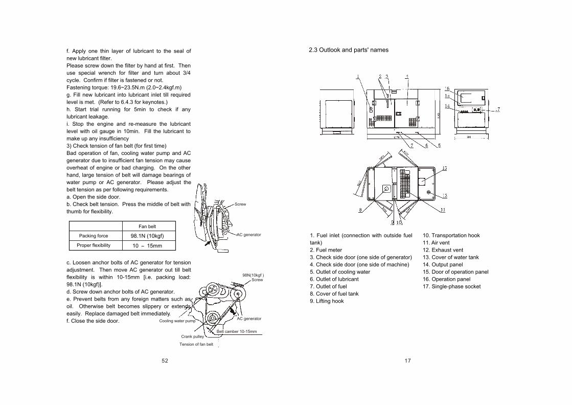
17
1. Fuel inlet (connection with outside fuel
tank)
2. Fuel meter
3. Check side door (one side of generator)
4. Check side door (one side of machine)
5. Outlet of cooling water
6. Outlet of lubricant
7. Outlet of fuel
8. Cover of fuel tank
9. Lifting hook
2.3 Outlook and parts' names
10. Transportation hook
11. Air vent
12. Exhaust vent
13. Cover of water tank
14. Output panel
15. Door of operation panel
16. Operation panel
17. Single-phase socket
52
Screw
AC generator
98N(10kgf ) Screw
AC generator
Tension of fan belt
Belt camber 10-15mm Crank pulley
Cooling water pump
f. Apply one thin layer of lubricant to the seal of
new lubricant filter.
Please screw down the filter by hand at first. Then
use special wrench for filter and turn about 3/4
cycle. Confirm if filter is fastened or not.
Fastening torque: 19.6~23.5N.m (2.0~2.4kgf.m)
g. Fill new lubricant into lubricant inlet till required
level is met. (Refer to 6.4.3 for keynotes.)
h. Start trial running for 5min to check if any
lubricant leakage.
i. Stop the engine and re-measure the lubricant
level with oil gauge in 10min. Fill the lubricant to
make up any insufficiency
3) Check tension of fan belt (for first time)
Bad operation of fan, cooling water pump and AC
generator due to insufficient fan tension may cause
overheat of engine or bad charging. On the other
hand, large tension of belt will damage bearings of
water pump or AC generator. Please adjust the
belt tension as per following requirements.
a. Open the side door.
b. Check belt tension. Press the middle of belt with
thumb for flexibility.
c. Loosen anchor bolts of AC generator for tension
adjustment. Then move AC generator out till belt
flexibility is within 10-15mm [i.e. packing load:
98.1N (10kgf)].
d. Screw down anchor bolts of AC generator.
e. Prevent belts from any foreign matters such as
oil. Otherwise belt becomes slippery or extends
easily. Replace damaged belt immediately.
f. Close the side door.
Packing force
Proper flexibility
Fan belt
98.1N (10kgf)
10 15mm
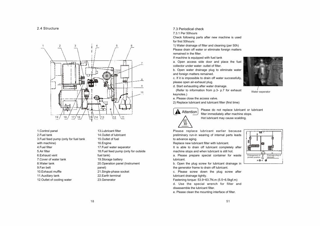
18
1 2 3 4 5 6
7
8
9
10
111213141516171819
2.4 Structure
1.Control panel
2.Fuel tank
3.Fuel feed pump (only for fuel tank
with machine)
4.Fuel filter
5.Air filter
6.Exhaust vent
7.Cover of water tank
8.Water tank
9.Fan belt
10.Exhaust muffle
11.Auxiliary tank
12.Outlet of cooling water
13.Lubricant filter
14.Outlet of lubricant
15.Outlet of fuel
16.Engine
17.Fuel/ water separator
18.Fuel feed pump (only for outside
fuel tank)
19.Storage battery
20.Operation panel (Instrument
panel)
21.Single-phase socket
22.Earth terminal
23.Generator
51
Attention
Water seperator
Please do not replace lubricant or lubricant
filter immediately after machine stops.
Hot lubricant may cause scalding.
Enlargement of printed position
Drainage plug of lubricant
7.3 Periodical check7.3.1 Per 50hours
Check following parts after new machine is used
for first 50hours:
1) Water drainage of filter and cleaning (per 50h)
Please drain off water or eliminate foreign matters
remained in the filter.
If machine is equipped with fuel tank
a. Open access side door and place the fuel
collector under water- outlet of filter.
b. Open water drainage plug to eliminate water
and foreign matters remained.
c. If it is impossible to drain off water successfully,
please open air-exhaust plug.
d. Start exhausting after water drainage.
(Refer to information from p.3- p.7 for exhaust
keynotes.)
e. Please close the access valve.
2) Replace lubricant and lubricant filter (first time)
Please replace lubricant earlier because
preliminary run-in wearing of internal parts leads
to advance aging.
Replace new lubricant filter with lubricant.
It is able to drain off lubricant completely after
machine stops and when lubricant is still hot.
a. Please prepare special container for waste
lubricant.
b. Open the plug screw for lubricant drainage in
the generator frame to drain off lubricant.
c. Please screw down the plug screw after
lubricant drainage tightly.
Fastening torque: 53.9~63.7N.m (5.5~6.5kgf.m)
d. Use the special wrench for filter and
disassemble the lubricant filter.
e. Please clean the mounting interface of filter.
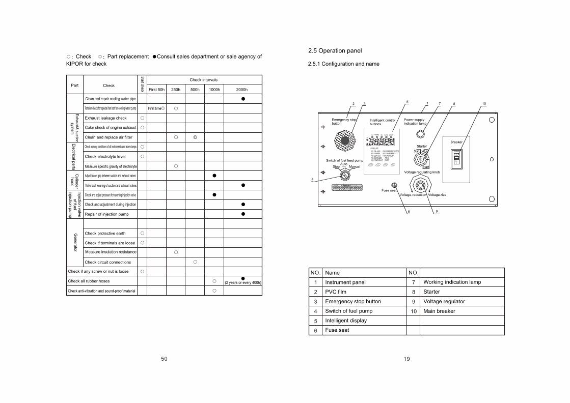
19
NO.
1
2
3
4
5
6
NO.
7
8
9
10
2.5 Operation panel
2.5.1 Configuration and name
Emergency stop button
Intelligent control buttons
Power supply indication lamp
Switch of fuel feed pump
Starter
Stop Manual
Fuse seat
Voltage regulating knob
Voltage-reduction Voltage-rise
Start Run
Breaker
Start
Working indication lamp
Starter
Voltage regulator
Main breaker
Name
Instrument panel
PVC film
Emergency stop button
Switch of fuel pump
Intelligent display
Fuse seat
50
Check Part replacement Consult sales department or sale agency of
KIPOR for check
Part Check
Check intervals
Start check First 50h 250h 500h 1000h 2000h
Exhaust leakage check
Clean and replace air filter
Check electrolyte level
Repair of injection pump
Check protective earth
Check if terminals are loose
Check circuit connections
Check if any screw or nut is loose
Check all rubber hoses
Check anti-vibration and sound-proof material
Clean and repair cooling-water pipe
Tension check for special fan belt for cooling water pump
Color check of engine exhaust
Check working conditions of all instruments and alarm lamps
Measure specific gravity of electrolyte
Adjust faucet gap between suction and exhaust valves
Valve seat wearing of suction and exhaust valves
Check and adjust pressure for opening injection valve
Check and adjustment during injection
Measure insulation resistance
First time
Exh
au
st& su
ction
system
Ele
ctrical p
arts
Cylin
de
r h
oo
d
Inje
ction
valve
o
f fue
l in
jectio
n p
um
p
Ge
ne
rato
r
(2 years or every 400h)
Auto
Attention
Start the machine when selection switch is at Off provided that thereis no outside fuel tank.
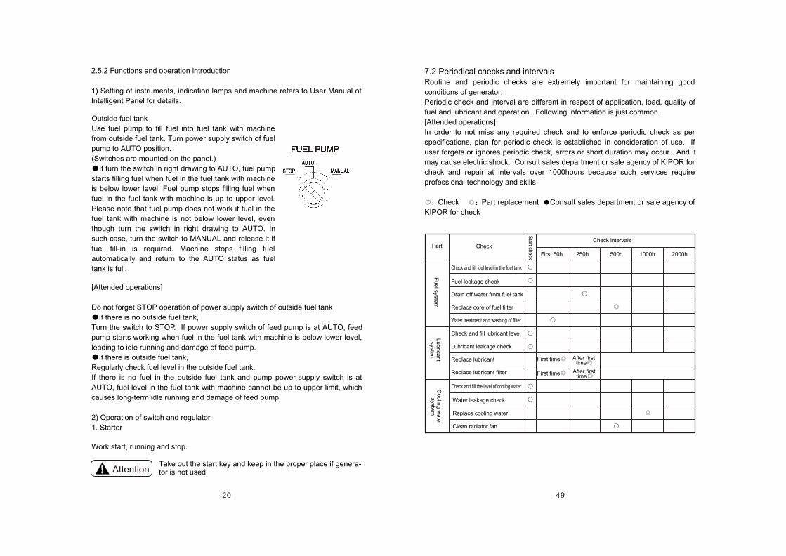
20
Outside fuel tank
Use fuel pump to fill fuel into fuel tank with machine
from outside fuel tank. Turn power supply switch of fuel
pump to AUTO position.
(Switches are mounted on the panel.)
If turn the switch in right drawing to AUTO, fuel pump
starts filling fuel when fuel in the fuel tank with machine
is below lower level. Fuel pump stops filling fuel when
fuel in the fuel tank with machine is up to upper level.
Please note that fuel pump does not work if fuel in the
fuel tank with machine is not below lower level, even
though turn the switch in right drawing to AUTO. In
such case, turn the switch to MANUAL and release it if
fuel fill-in is required. Machine stops filling fuel
automatically and return to the AUTO status as fuel
tank is full.
[Attended operations]
Do not forget STOP operation of power supply switch of outside fuel tank
If there is no outside fuel tank,
Turn the switch to STOP. If power supply switch of feed pump is at AUTO, feed
pump starts working when fuel in the fuel tank with machine is below lower level,
leading to idle running and damage of feed pump.
If there is outside fuel tank,
Regularly check fuel level in the outside fuel tank.
If there is no fuel in the outside fuel tank and pump power-supply switch is at
AUTO, fuel level in the fuel tank with machine cannot be up to upper limit, which
causes long-term idle running and damage of feed pump.
2) Operation of switch and regulator
1. Starter
Work start, running and stop.
2.5.2 Functions and operation introduction
1) Setting of instruments, indication lamps and machine refers to User Manual of
Intelligent Panel for details.
AttentionTake out the start key and keep in the proper place if genera-tor is not used.
49
Fu
el syste
mL
ub
rican
t syste
m
7.2 Periodical checks and intervalsRoutine and periodic checks are extremely important for maintaining good
conditions of generator.
Periodic check and interval are different in respect of application, load, quality of
fuel and lubricant and operation. Following information is just common.
[Attended operations]
In order to not miss any required check and to enforce periodic check as per
specifications, plan for periodic check is established in consideration of use. If
user forgets or ignores periodic check, errors or short duration may occur. And it
may cause electric shock. Consult sales department or sale agency of KIPOR for
check and repair at intervals over 1000hours because such services require
professional technology and skills.
Check Part replacement Consult sales department or sale agency of
KIPOR for check
Part Check Check intervals
Co
olin
g w
ate
r syste
m
Fuel leakage check
Drain off water from fuel tank
Replace core of fuel filter
Check and fill lubricant level
Lubricant leakage check
Replace lubricant
Replace lubricant filter
Start check
Water leakage check
Replace cooling water
Clean radiator fan
First 50h 250h 500h 1000h 2000h
First time
First time
After first time
After first time
Check and fill fuel level in the fuel tank
Water treatment and washing of filter
Check and fill the level of cooling water
21
OFF
Breaker
Do not operate loading equipment
ON/OFF with the breaker.
Indicate start position of engine. In the case that starter is turned to this position,
machine is preheated and starts. If operator releases the start key, starter returns
to ON automatically.
Pre-heating (HEAT)
Automatically start pre-heating upon start of intelligent panel controller. Operator
can define preheating time.
When intelligent display shows PRE-H, machine is preheated. After preheating,
machine automatically enters into start procedure. When intelligent display
shows START, machine is running.
2. Main breaker
Functions are:
To supply power produced by generator to main switch of
3-phase joint of output terminal block
Automatically cut off the switch when loading equipment is
at short-circuit or over-load. Protect the generator.
It is at OFF when engine starts. It is at ON when power
is used.
OFF
Indicate that start key is taken out and engine
stops.
Intelligent indication lamps are all off.
ON
Keep the position when machine works.
START
[Attended operations]
Do not operate loading equipment ON/OFF with the breaker. If user requires
ON/OFF function, add Load ON/ OFF switch between 3-phase joint and loading
equipment. Otherwise there are some errors of breaker.
If there is over current, regulating handle of breaker maintains between ON and
OFF when breaker is cutoff. This condition is named tripping. By then turn
regulating handle downward to OFF. If regulating handle does not return to
original position, it is not allowed to turn regulating handle to ON.
48
Item Diameter of bolt x pitch Remark
M20 2.5
M6 1
M8 1.25
M10 1.5
M12 1.75
M14 2
M16 2
M18 2.5
323.6 402.1 33 41
9.8 11.8 1.0 1.2
22.6 28.4 2.3 2.9
44.1 58.8 4.5 6.0
78.5 98.1 8.0 10
117.7 147.1 12 15
166.7 206.0 17 21
235.4 284.4 24 29
210.8 240.3 21.5 24.5
M14 1.5
M16 1.5
127.5 147.1 13 15
49.0 58.8 5.0 6.0
M8
M12
M14
12.7 16.7 1.3 1.7
M16
24.5 34.3 2.5 3.5
39.2 49.0 4.0 5.0
Consult sales department or sale agency of KIPOR for necessary repair such as
disassembly of parts.
7.1.1 Torque list
Fasten bolts and nuts in metric unit, if no other specification, in accordance with
torque listed in the below table.
1) If fastening unit is
in aluminum, torque
shall be only 80% of
listed value.
2) For 4T bolts and
holding nuts, torque
shall be 60% of listed
value.
3) Apply fine thread
just for the engine.
Fastening torque [N. m (kgf.m)]
Co
mm
on
thre
ad
Hex bolt (7T)
and nut
Pipe connection thread
Fine thread
22
MAX
MIN
50Hz(V)
250 2
200
60Hz(V)
260 2
210
3. Voltage regulator
It is used to regulate output voltage. If turn it right, voltage rises. If turn it left,
voltage falls down.
Voltage regulation range
4. Fuse
(1) Preheating circuit: fuse (capacity: 50A)
(2) Charging circuit: fuse (capacity: 20A)
(3) Circuit of control power-supply: fuse (capacity: 10A)
2.5.3 Functions and identification of protectors
This generator is equipped with error protectors. Machine automatically stops
engine or disconnects with load as below description in case of serious errors.
Meanwhile intelligent panel shows abnormal parts with relative codes. For small
errors, alarm lamps and sound are available.
[Attended operations]
Immediately stop the machine and start check and repair if there is any error.
Accident is possible if abnormal machine is still running.
NO.
1
2
3
4
5
6
7
8
ErrorDescription
Auto stop Auto cutoff
P-01
P-08
P-03
P-07
P-04
P-02
P-05
P-06
Intelligent panel display
Indicate alarmAbnormalNormal
Reduction of lubricant pressure
Temperature-rise of cooling water
Bad charging of storage battery
Over-voltage
Over-current
Over-frequency
Start error
Emergency stop
47
7.1 Check
Please carry out periodic check.
Aging and performance fall appear if engine runs for long term.
Accident and error may occur if no check, maintenance and care. Cause great
consumption of fuel and lubricant, bad exhaust and large noise. In addition
duration of engine becomes shorter. Therefore routine and periodic check and
maintenance can effectively avoid error occurrence. In addition, periodic check
on electricity system can avoid electric shock.
Please observe pre-start checks
Implement routine and periodic check before work every day. It is a good practice
to do routine check before machine starts every day.
(Refer to 6.4.1 for keynotes about check before work.)
Periodic check as per running record
Establish the running record for daily operation, maintenance and check.
Periodic check is divided into several intervals like 50hours, 250hours, 500hours,
1000hours and 2000hours. If running time of machine approaches defined check
interval, please do periodic check as per requirements.
Please use our original parts.
Replace damaged parts with our original parts.
Otherwise, its mechanical performance falls or duration of engine turns shorter.
Prepare special tools for check and maintenance
For regular check on generator, prepare maintenance tools and maintenance in
the place neighboring to generator
Provide user periodic check and repair
Professional maintenance technicians provide user maintenance, check and
repair.
Consult sales department or sale agency of KIPOR.
Torque for fastening bolts and nuts
If bolts and nuts are fastened too tightly, it is possible to break bolts or damage
thread. On the other hand, oil leakage at mounting surface is possible, or loose
bolts may damage parts if fastening torque is too small. Therefore please fasten
bolts and nuts with specified torque tightly.
Fasten important parts with torque wrench in accordance with specified torque
and correct fastening method and order. Gradually fasten parts till required torque
is met.
7. Maintenance and check
23
3. Connection of load
If one set is used If two sets are used If three sets are usedU
V
W
U
V
W
U
V
W
Electric welder
3.1 Capacity of motor[Attended operations]
If select the motor with improper capacity, it is impossible to start the motor.
Decide the capacity of motor as per followings:
According to type, application, start method, quantity and operating power of
motor, features of generator, type of auto voltage regulator, starting capacity of
generator is different.
Upon starting motor, its current is 5-8times of rated current. Its rapid rise of
starting current causes instant overload of generator. Then voltage of generator
falls down rapidly. Therefore sometimes it is difficult to start the motor.
It is recommended to discuss with manufacturer of motor upon decision of
capacity. User can calculate the capacity simply with below formulas.
Input power of squirrel-cage asynchronous motor (kVA)
Power factor of motor: 0.8 Motor efficiency: 0.8
Input power (kVA)=1.56x rated power of motor (kW)
Direct-starting squirrel-cage asynchronous motor (with knife switch)
Generator capacity = 2x input power of motor
Direct-starting squirrel-cage motor (with contactor)
Generator capacity = 3x input power of motor
Star/ triangular-starting squirrel-cage motor
Generator capacity = 1.2~1.5x input power of motor
It is required to balance the load if more than one AC electric welder is used.
Therefore user shall distribute phases equally as per following:
[Attended operations]
Input power of one electric welder shall be below 1/3 of output power of generator.
Over-load may cause motor damage.
Motor efficiency x Power factor
Input power (kVA)=Rated power of motor (kW)
Electric welder
Electric welder
Electric welder
Electric welder
Electric welder
46
Cover of water inlet
Drainage fuel ofcooling water
Fuel access stick
Drainage plug
[Attended operations]
It is necessary to drain off cooling water. Otherwise rest cooling water in the
engine may freeze and expand thus to damage the machine.
d. Close radiator cover, hood and drainage plug after drainage finishes.
2)Please clean mud, dust and oil remained on the machine surface.
3)Must finish periodic check prior to maintenance.
4)In order to prevent dew concentration in the fuel tank. Drain off fuel or fill fuel
completely.
5)Disconnect cable of storage battery with (-) pole.
6)Apply lubricant to operating devices and relevant connections.
7)Please cover the plastic hood and similar parts in order to prevent water or dust
into control box, radiator and muffle of exhaust pipe.
8)Store the machine in the place without moisture or dust and with good
ventilation.
9)Please charge the storage battery once per month to resolve intrinsic shelf
depreciation during machine storage.
10)Please do no-load running for short time and at low speed if machine is idle for
6.5 Long-term storagePlease implement following maintenance for the
generator idle for long-term.
1) Drain off cooling water in cold season or at
the status of long-term storage.
(Mentioned action is no need if anti-freezing
liquid is used.)
a. Take off upper hood and open radiator cover.
b. Take off drainage plug of cooling water in the
frame of generator to drain inside water.
c. Loosen the drainage plug at the side of
cylinder and drain out the water.
24
Danger
Danger
3.2 Selection of 3-phase cable
[Attended operations]
Please select the cable with proper diameter after taking
into account tolerable current of cable and distance from
generator to loading equipments.
If load current exceeds tolerable current, lead is burnt to
damage due to over-heat. In addition, following conditions
also can cause lead damage such as too long cable, super-
small diameter, excessively large voltage-drop of lead,
reduction of input voltage of loading equipments, or
reduction of efficiency of loading equipments.
3.3 Connection of loading equipment
Touching output terminal of running machine may cause
electric shock even death risk, particularly when hands are
wet.
Start connection work after cut off breaker and stop
running machine.
(If machine is run with shunt feeding, please cut off power
feeder outside of machine.)
Application of damaged cable may cause electric shock.
Forbid using such cable.
Laws forbid connecting power supply of generator with
inside distributing line (common distributing line accepting
power from the power company).
If connection with inside distributing line, there is over-
current of inside distributing line and generator thus to
cause fire or electric shock accident.
Please do not connect the machine with inside
distributing line.
45
1
2
3
4
5
6
Breaker of loading equipments at OFF
If any outside fuel tank
After start, it returns to O N position if hand releases it.
7
8
9
10
11
8
13
14
15
16
No load
No loading voltage
Breaker at no-load side to ON
Run the cold machine in cold season
Turn to START
6.4.6 Start procedure
Show main operations with below No.-marked process drawing. Stop operations
in the reverse order of No. 9, 8, 4 and 2after loading equipments stop.
Start check
Breaker
[OFF]
If switch position of fuel feed pump is correct or not
Start switch
[ON]
Start switch
[Start]
Start switch
[OFF]
Heat and run the
machine [5min]
Heat and runthe machine[within 10min]
Adjust freque-
ncy [Regulator]
Start the
engine
Adjust voltage
[Voltage regulator]
Check prior to
load running
Breaker [ON] (start supplying power)
Load
equipments
Adjust frequency
and voltage
Run the loading
equipments
Confirm if ? indication lamps are on
At OFF position after machine stops
(In cold season)
Check all instruments and ?indication lamps
Check ? gas color, vibration and abnormal sound
Check all instruments and ? indication lamps
Check ? gas color, vibration and abnormal sound
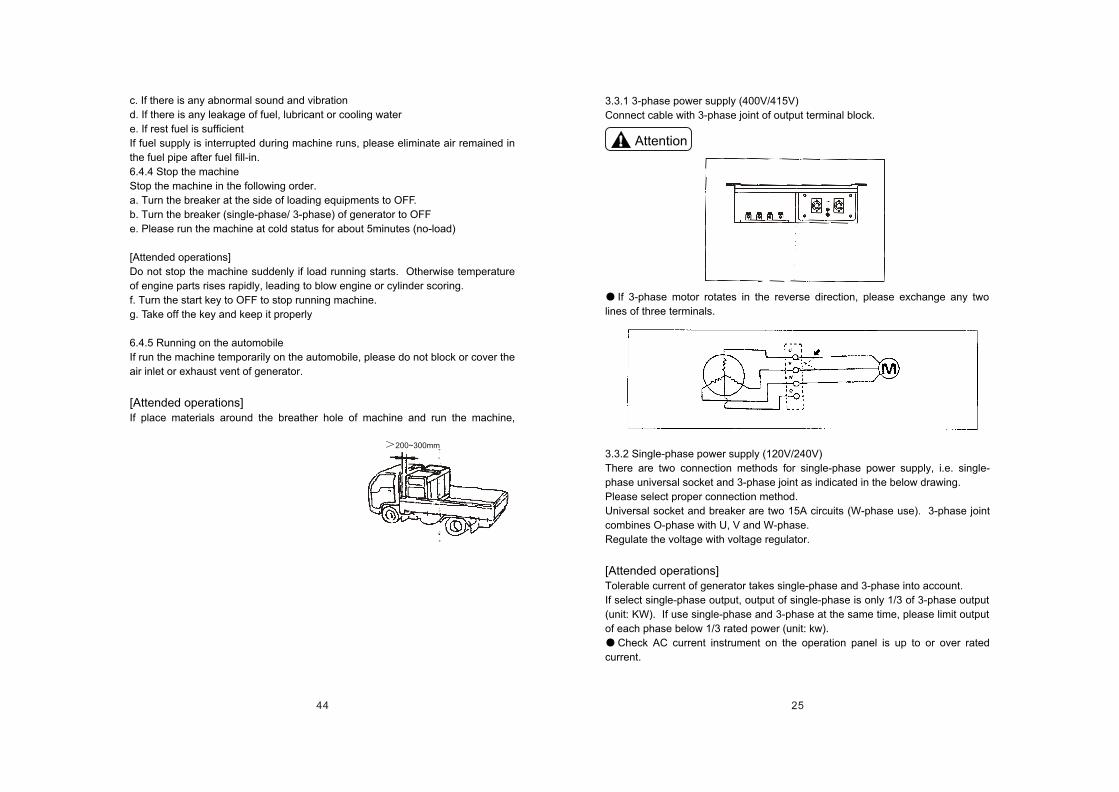
25
Attention
3.3.1 3-phase power supply (400V/415V)
Connect cable with 3-phase joint of output terminal block.
If 3-phase motor rotates in the reverse direction, please exchange any two
lines of three terminals.
3.3.2 Single-phase power supply (120V/240V)
There are two connection methods for single-phase power supply, i.e. single-
phase universal socket and 3-phase joint as indicated in the below drawing.
Please select proper connection method.
Universal socket and breaker are two 15A circuits (W-phase use). 3-phase joint
combines O-phase with U, V and W-phase.
Regulate the voltage with voltage regulator.
[Attended operations]Tolerable current of generator takes single-phase and 3-phase into account.
If select single-phase output, output of single-phase is only 1/3 of 3-phase output
(unit: KW). If use single-phase and 3-phase at the same time, please limit output
of each phase below 1/3 rated power (unit: kw).
Check AC current instrument on the operation panel is up to or over rated
current.
44
200~300mm
c. If there is any abnormal sound and vibration
d. If there is any leakage of fuel, lubricant or cooling water
e. If rest fuel is sufficient
If fuel supply is interrupted during machine runs, please eliminate air remained in
the fuel pipe after fuel fill-in.
6.4.4 Stop the machine
Stop the machine in the following order.
a. Turn the breaker at the side of loading equipments to OFF.
b. Turn the breaker (single-phase/ 3-phase) of generator to OFF
e. Please run the machine at cold status for about 5minutes (no-load)
[Attended operations]
Do not stop the machine suddenly if load running starts. Otherwise temperature
of engine parts rises rapidly, leading to blow engine or cylinder scoring.
f. Turn the start key to OFF to stop running machine.
g. Take off the key and keep it properly
6.4.5 Running on the automobile
If run the machine temporarily on the automobile, please do not block or cover the
air inlet or exhaust vent of generator.
[Attended operations]If place materials around the breather hole of machine and run the machine,
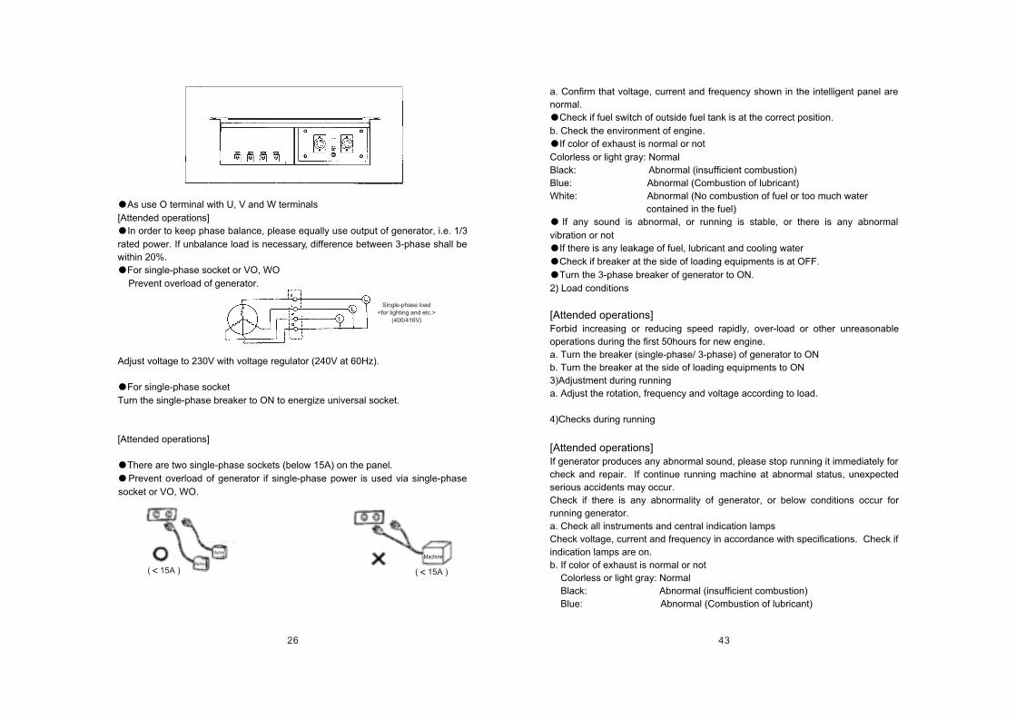
26
Machine
As use O terminal with U, V and W terminals
[Attended operations]
In order to keep phase balance, please equally use output of generator, i.e. 1/3
rated power. If unbalance load is necessary, difference between 3-phase shall be
within 20%.
For single-phase socket or VO, WO
Prevent overload of generator.
Adjust voltage to 230V with voltage regulator (240V at 60Hz).
For single-phase socket
Turn the single-phase breaker to ON to energize universal socket.
[Attended operations]
There are two single-phase sockets (below 15A) on the panel.
Prevent overload of generator if single-phase power is used via single-phase
socket or VO, WO.
( 15A ) ( 15A )Machine
Machine
Single-phase load
<for lighting and etc.>
(400/416V)
43
a. Confirm that voltage, current and frequency shown in the intelligent panel are
normal.
Check if fuel switch of outside fuel tank is at the correct position.
b. Check the environment of engine.
If color of exhaust is normal or not
Colorless or light gray: Normal
Black: Abnormal (insufficient combustion)
Blue: Abnormal (Combustion of lubricant)
White: Abnormal (No combustion of fuel or too much water
contained in the fuel)
If any sound is abnormal, or running is stable, or there is any abnormal
vibration or not
If there is any leakage of fuel, lubricant and cooling water
Check if breaker at the side of loading equipments is at OFF.
Turn the 3-phase breaker of generator to ON.
2) Load conditions
[Attended operations]Forbid increasing or reducing speed rapidly, over-load or other unreasonable
operations during the first 50hours for new engine.
a. Turn the breaker (single-phase/ 3-phase) of generator to ON
b. Turn the breaker at the side of loading equipments to ON
3)Adjustment during running
a. Adjust the rotation, frequency and voltage according to load.
4)Checks during running
[Attended operations]If generator produces any abnormal sound, please stop running it immediately for
check and repair. If continue running machine at abnormal status, unexpected
serious accidents may occur.
Check if there is any abnormality of generator, or below conditions occur for
running generator.
a. Check all instruments and central indication lamps
Check voltage, current and frequency in accordance with specifications. Check if
indication lamps are on.
b. If color of exhaust is normal or not
Colorless or light gray: Normal
Black: Abnormal (insufficient combustion)
Blue: Abnormal (Combustion of lubricant)
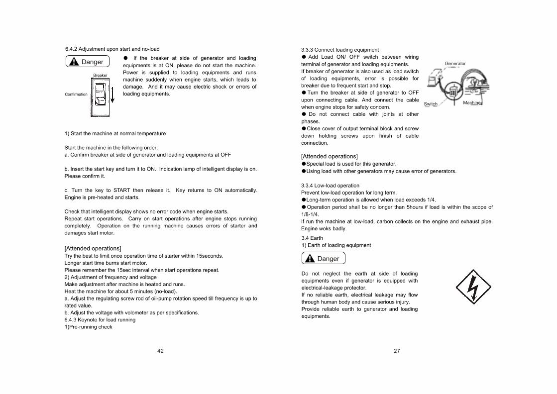
27
Generator
Switch Machine
3.3.3 Connect loading equipment
Add Load ON/ OFF switch between wiring
terminal of generator and loading equipments.
If breaker of generator is also used as load switch
of loading equipments, error is possible for
breaker due to frequent start and stop.
Turn the breaker at side of generator to OFF
upon connecting cable. And connect the cable
when engine stops for safety concern.
Do not connect cable with joints at other
phases.
Close cover of output terminal block and screw
down holding screws upon finish of cable
connection.
[Attended operations]Special load is used for this generator.
Using load with other generators may cause error of generators.
3.3.4 Low-load operation
Prevent low-load operation for long term.
Long-term operation is allowed when load exceeds 1/4.
Operation period shall be no longer than 5hours if load is within the scope of
1/8-1/4.
If run the machine at low-load, carbon collects on the engine and exhaust pipe.
Engine woks badly.
Danger
3.4 Earth
1) Earth of loading equipment
Do not neglect the earth at side of loading
equipments even if generator is equipped with
electrical-leakage protector.
If no reliable earth, electrical leakage may flow
through human body and cause serious injury.
Provide reliable earth to generator and loading
equipments.
42
Danger
OFF
1) Start the machine at normal temperature
Start the machine in the following order.
a. Confirm breaker at side of generator and loading equipments at OFF
b. Insert the start key and turn it to ON. Indication lamp of intelligent display is on.
Please confirm it.
c. Turn the key to START then release it. Key returns to ON automatically.
Engine is pre-heated and starts.
Check that intelligent display shows no error code when engine starts.
Repeat start operations. Carry on start operations after engine stops running
completely. Operation on the running machine causes errors of starter and
damages start motor.
[Attended operations]Try the best to limit once operation time of starter within 15seconds.
Longer start time burns start motor.
Please remember the 15sec interval when start operations repeat.
2) Adjustment of frequency and voltage
Make adjustment after machine is heated and runs.
Heat the machine for about 5 minutes (no-load).
a. Adjust the regulating screw rod of oil-pump rotation speed till frequency is up to
rated value.
b. Adjust the voltage with volometer as per specifications.
6.4.3 Keynote for load running
1)Pre-running check
If the breaker at side of generator and loading
equipments is at ON, please do not start the machine.
Power is supplied to loading equipments and runs
machine suddenly when engine starts, which leads to
damage. And it may cause electric shock or errors of
loading equipments.
6.4.2 Adjustment upon start and no-load
Confirmation
Breaker
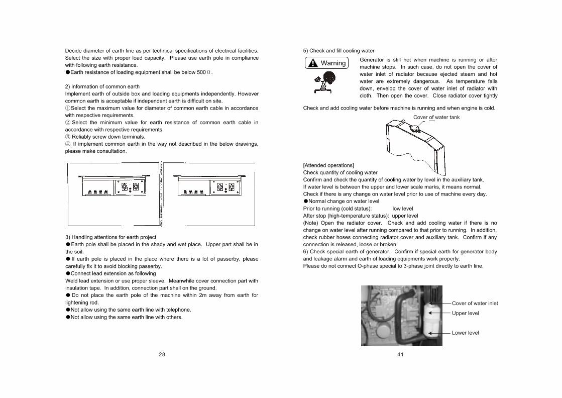
28
Decide diameter of earth line as per technical specifications of electrical facilities.
Select the size with proper load capacity. Please use earth pole in compliance
with following earth resistance.
Earth resistance of loading equipment shall be below 500 .
2) Information of common earth
Implement earth of outside box and loading equipments independently. However
common earth is acceptable if independent earth is difficult on site.
Select the maximum value for diameter of common earth cable in accordance
with respective requirements.
Select the minimum value for earth resistance of common earth cable in
accordance with respective requirements.
Reliably screw down terminals.
If implement common earth in the way not described in the below drawings,
please make consultation.
3) Handling attentions for earth project
Earth pole shall be placed in the shady and wet place. Upper part shall be in
the soil.
If earth pole is placed in the place where there is a lot of passerby, please
carefully fix it to avoid blocking passerby.
Connect lead extension as following
Weld lead extension or use proper sleeve. Meanwhile cover connection part with
insulation tape. In addition, connection part shall on the ground.
Do not place the earth pole of the machine within 2m away from earth for
lightening rod.
Not allow using the same earth line with telephone.
Not allow using the same earth line with others.
41
Cover of water tank
Cover of water inlet
Upper level
Lower level
5) Check and fill cooling water
Check and add cooling water before machine is running and when engine is cold.
[Attended operations]
Check quantity of cooling water
Confirm and check the quantity of cooling water by level in the auxiliary tank.
If water level is between the upper and lower scale marks, it means normal.
Check if there is any change on water level prior to use of machine every day.
Normal change on water level
Prior to running (cold status): low level
After stop (high-temperature status): upper level
(Note) Open the radiator cover. Check and add cooling water if there is no
change on water level after running compared to that prior to running. In addition,
check rubber hoses connecting radiator cover and auxiliary tank. Confirm if any
connection is released, loose or broken.
6) Check special earth of generator. Confirm if special earth for generator body
and leakage alarm and earth of loading equipments work properly.
Please do not connect O-phase special to 3-phase joint directly to earth line.
Warning Generator is still hot when machine is running or after
machine stops. In such case, do not open the cover of
water inlet of radiator because ejected steam and hot
water are extremely dangerous. As temperature falls
down, envelop the cover of water inlet of radiator with
cloth. Then open the cover. Close radiator cover tightly
29
Lifting hook
Lifting hook
Transportation hook
4. Transportation and overlapping-storage
4.1 Lifting attentions
Lift generator with the lifting hook on the top of cover. If lifting the generator
with transportation hook or other parts, there is the risk of mechanical damage or
falling-down.
Do not stand under the lifted generator.
Do not lift or move the running generator. Some irrevocable errors like fan
damage may occur.
4.2 Transportation attentions
[Attended operations]
If shipping with the truck, please fix the generator on the loading table in the truck
for safety concern.
40
Danger
6.4 Operation
Run the machine with all instruments on the operation panel.
6.4.1 Pre-start checks
Carry on following checks prior to each start.
1) Remove foreign matters in the generator
Check if there is any tool or rag in the generator.
Check if there is any rubbish or inflammable matter around muffle or engine. If
any, remove it away immediately.
Check if suction inlet and exhaust vent of generator is jammed by rubbish or
rag. If any, remove it away immediately.
2) Check in the generator
Any oil leakage in the engine
Any fuel leakage in the fuel system
Any water leakage in cooling water system
Broken distribution line, short circuit or loose joint
Check if any screw is loose or released.
Do not run the machine before eliminating any founded abnormality.
3) Check and fill fuel
Regularly check rest fuel level in the fuel tank and add recommended fuel on time
(refer to 6.3.1).
4) Check and fill lubricant
Check lubricant level with oil gauge.
Add recommended diesel lubricant from oil-inlet of gear chamber when oil level
is insufficient.
Check the lubricant with oil gauge. Add lubricant up to upper scale mark with
check (refer to 6.3.3).
Following parts in the running generator are extremely
dangerous, such as radiator fan, belt and other rotation
parts, engine, cylinder hood, exhaust pipe, muffle and
other parts at high temperature and high voltage.
Close the side door of running machine.
Stop running machine before check and maintenance.
30
Horizontal loading Longitudinal loading
Rope
Bind the generator with ropes at left and right hands indicated on below drawings
after loading.
4.3 Overlapping-storage attentions
[Attended operations]
Please store generators as following if two-
layers storage is required.
Check if generator hood is damaged or
screw is loose or released.
Check if the ground is flat and solid and
can bear static weight of overlapped
generators.
l Place the wooden lumps between
generators.
l Prevent generators in the upper layer
from inclination.
l Prevent generators in the upper layer
heavier than those in the lower layer.
Do not run the generator at the status of
storage.
Rope
Rope
39
Add cooling water as per following procedures. Please
add anti-freezing liquid into cooling water.
Fill water into radiator
a. Turn the cover of radiator towards left side and take
it off.
b. Add the cooling water till it overflows from water inlet
of radiator. Slowly fill cooling water to avoid any foam.
c. Close the cover of radiator tightly to prevent any
water leakage. Direct the inside clip towards notch of
water inlet. Then press down the cover and turn the
cover towards right side for 1/3 cycle to close the cover.
Fill water into overflow bucket of auxiliary tank
d. Please take off the cover of water inlet of auxiliary
tank. Add cooling water up to the upper scale mark.
Then re-mount the cover.
e. Check if joints of rubber hoses connecting auxiliary
tank and radiator are loose, released or damaged. If
any, auxiliary tank cannot work.
6.3.5 Trial running
Run the generator that is new or idle for long-term at low speed and without load
for short term before load running. Deliver the lubricant to all abrasion parts. If
start the load running without mentioned operation, it may cause abnormal
abrasion or damage to piston, cylinder sleeve, crank shaft, bearing and other
parts.
a. Turn the breaker of generator to OFF.
b. Insert the start key and turn it to START. Then engine starts. Run the engine
for about 5min to check if any abnormal sound and leakage of water, oil and gas.
c. Turn the key to OFF and stop engine.
6.3.6 Quantity re-confirmation of lubricant and cooling water
Please re-confirm the quantity of lubricant and cooling water after 5-minute trial
running, if lubricant or cooling water is filled into for the first time or is replaced.
Trial running distributes lubricant and cooling water around the machine. During
re-check level of lubricant and cooling water shall be lower. By then, please
make up insufficiency.
Add lubricant (refer to 6.3.3)
Add cooling water (refer to 6.3.4)
31
Danger
5. Installation
Please work the machine in the well-ventilated place. Bad
ventilation causes breath of waste gas thus to death.
Do not work the generator in the building or place with
cover, bad ventilation or static exhaust.
Do not work the generator in the place with bad
ventilation such as inside stockroom, tunnel, cabin or
enclosure channel.
If it is necessary to run the machine on mentioned
conditions, necessarily extend exhaust pipe outside of
room and provide proper ventilation device to ensure
sufficient ventilation.
Mount the plug to water outlet of exhaust muffle and
ensure no leakage of waste gas. Otherwise there is risk of
leakage of waste gas.
Prevent exhaust vent direct to passerby or other's family.
Pay attention to vibrationRunning machine produces vibration as inside engine is working.
Please observe the following requirements upon installation.
Place the machine on the solid ground and keep it level.
Abnormal vibration may occur if machine runs on the uneven ground.
Therefore please install the machine after solid foundation is completely finished.
Consult local KIPOR sales department for detailed information concerning
vibration specification and foundation project.
Pay attention to noise.There is great noise if operator opens the side door as inside engine is working.
In addition, there is still certain noise even if side door is close.
Close the side door after machine is installed.
If there is uptown around, residents may complain about noise. Therefore
please take additional measures against noise. Consult local KIPOR sales
department for detailed information concerning noise specification.
This generator is portable and used as main or auxiliary power supply for
outside work. Installation shall consider below requirements.
38
ID 12
2) Recommended fuel
Light diesel
3) Keynotes for piping
Fase fix outside fuelinlet with clip
Fuel fill-in pipe
Clip
Access door
Attention
Warning
6.3.3 Fill lubricant
a. Keep engine level upon lubricant fill-in.
b. Take off the yellow cover of lubricant inlet on the top of gear chamber. Add
recommended diesel up to the upper mark of oil gauge.
c. Measure the lubricant with oil gauge. In order to get correct level, please clean
the oil gauge before inserting it into lubricant. Lubricant trace remained on the oil
gauge indicates measurement.
Re-confirm it after 3-5min running.
Volume of lubricant: 6.9L
6.3.4 Fill cooling water
Close the cover of radiator water inlet tightly.
Otherwise, ejected steam or hot water may cause
scalding.
Keep lubricant level between upper and lower scale
marks. Lubricant level shall not exceed the upper mark.
Ejection of lubricant from the breather hole may cause
engine errors.
32
200~300mm
Radiator side
[Attended operations]
Please install the machine on the flat and solid ground. Make sure bottom of the
generator contacts ground evenly. Error may occur due to generator vibration.
If it is necessary to run the machine on the inclined ground, make sure the side
with radiator upward and inclination angle within 10 . Engine may face over-
heat due to bad working of water temperature switch, air into cooling water pipe
and etc.
Keep machine at least 200-300mm away from walls upon installation. Keep air
vent of radiator and suction inlet and exhaust vent of engine upward. Prevent
them from any jam. Otherwise temperature rise or reduction of cooling airflow
may cause over-heat of engine or reduction of rotation. In addition, temperature
of exhaust or increase of load also may lead to shorter duration.
Run the machine in the place free of moisture, dust and rubbish and with fresh
air.
Electricity leakage causes electric shock. If air vent of radiator is jammed, over-
heat of engine may occur.
Place the generator near to working equipments like motor, lamps and etc.
Long line reduces efficiency because of large resistance and electricity loss. And
electricity fee turns more.
Prevent releasing all loads of generator instantly. Please release loads
gradually and evenly.
Radiator side
Do not place any obstacle at air vent, suction vent and exhaust vent of radiator
Wall
37
6.3 Pre-start preparationsImplement pre-start preparations in the following order upon preliminary use.
6.3.1 Fill fuel
6.3.2 Keynotes for filling fuel with outside fuel tank
Ensure tight connection of fuel pipe with fuel inlet of outside fuel tank. Any
loose connection leads to fuel spill.
Idle running of fuel feed pump causes damage. Please pay more attention to
fuel level in the outside fuel tank. Try best to avoid idle running.
Location of outside fuel tank
Place the outside fuel tank within 5m away from generator.
In addition, foundation height for outside fuel tank must be within 0-5m.
Danger Fill the proper fuel. Improper fuel may lead to risk of fire.
Please confirm the type of fuel in advance.
Clean any overflowed fuel.
Fuel tank is provided with lock. Open the
lock and take off the cover of fuel tank.
Fill clean and clear fuel without water and
foreign matters into fuel tank.
In order to prevent any overflow when
machine is running, fill-in amount shall be
approximately 90% of tank volume.
Volume of fuel tank: 65L
Cover of fuel tank
View windowfor fuel
Outside fuel tank
Pipe length 5m
Generator
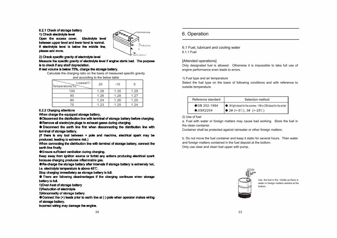
33
Use the fuel in the middle as there is
water or foreign matters residue at the
bottom.
6.1 Fuel, lubricant and cooling water6.1.1 Fuel
[Attended operations]Only designated fuel is allowed. Otherwise it is impossible to take full use of
engine performance even leads to errors.
1) Fuel type and air temperature
Select the fuel type on the basis of following conditions and with reference to
outside temperature.
2) Use of fuel
a. Fuel with water or foreign matters may cause bad working. Store the fuel in
the clean container.
Container shall be protected against rainwater or other foreign matters.
b. Do not move the fuel container and keep it static for several hours. Then water
and foreign matters contained in the fuel deposit at the bottom.
Only use clear and clean fuel upper with pump.
6. Operation
Reference standard Selection method
GB 252-1994
JISK2204
2# (>-5 ), 3# (>-25 )
0# light diesel for the summer, -10# or 20# diesel for the winter
36
100
90
80
75
20
1.28
1.26
1.24
1.23
-10 0
1.30
1.28
1.26
1.25
1.29
1.27
1.25
1.24
6.2.1 Check of storage battery
1) Check electrolyte level
Open the access cover. Electrolyte level
between upper level and lower level is normal.
If electrolyte level is below the middle line,
please add more.
6.2.1 Check of storage battery
1) Check electrolyte level
Open the access cover. Electrolyte level
between upper level and lower level is normal.
If electrolyte level is below the middle line,
please add more.
6.2.1 Check of storage battery
1) Check electrolyte level
Open the access cover. Electrolyte level
between upper level and lower level is normal.
If electrolyte level is below the middle line,
please add more.
6.2.1 Check of storage battery
1) Check electrolyte level
Open the access cover. Electrolyte level
between upper level and lower level is normal.
If electrolyte level is below the middle line,
please add more.
6.2.1 Check of storage battery
1) Check electrolyte level
Open the access cover. Electrolyte level
between upper level and lower level is normal.
If electrolyte level is below the middle line,
please add more.
6.2.1 Check of storage battery
1) Check electrolyte level
Open the access cover. Electrolyte level
between upper level and lower level is normal.
If electrolyte level is below the middle line,
please add more.
6.2.1 Check of storage battery
1) Check electrolyte level
Open the access cover. Electrolyte level
between upper level and lower level is normal.
If electrolyte level is below the middle line,
please add more.
2) Check specific gravity of electrolyte level
Measure the specific gravity of electrolyte level if engine starts bad. The purpose
is to check if any shelf depreciation.
If rest volume is below 75%, charge the storage battery.
6.2.2 Charging attentions
When charge the equipped storage battery,
Disconnect the distribution line with terminal of storage battery before charging.
Remove all electrolyte plugs to exhaust gases during charging.
Disconnect the earth line first when disconnecting the distribution line with
terminal of storage battery.
(If there is any tool between + pole and machine, electrical spark may be
produced, leading to extreme risk.)
When connecting the distribution line with terminal of storage battery, connect the
earth line finally.
Ensure sufficient ventilation during charging.
Keep away from ignition source or forbid any actions producing electrical spark
because charging produces inflammable gas.
Re-charge the storage battery after intervals if storage battery is extremely hot,
i.e. electrolyte temperature is above 45 .
Stop charging immediately as storage battery is full.
There are following disadvantages if the charging continues when storage
battery is full.
1)Over-heat of storage battery
2)Reduction of electrolyte
3)Abnormality of storage battery
Connect the (+) leads prior to earth line at (-) pole when operator makes wiring
of storage battery.
Incorrect wiring may damage the engine.
Calculate the charging ratio on the basis of measured specific gravity
and according to the below table
Temperature(%)Lowest
Electrolyte plug
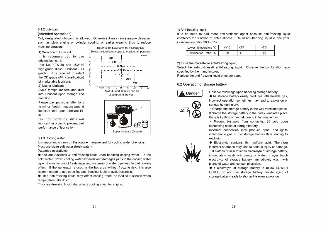
34 35
4L 20L 200L
Super lubricant (D grade)
6.1.2 Lubricant
[Attended operations]Only designated lubricant l is allowed. Otherwise it may cause engine damages
such as blow engine or cylinder scoring, or earlier wearing thus to reduce
machine duration.
6.1.3 Cooling water
It is important to carry on the routine management for cooling water of engine.
Must use clean soft water (fresh water).
[Attended operations]
Add anti-rustiness & anti-freezing liquid upon handling cooling water. In the
cold winter, frozen cooling water expands and damages parts in the cooling water
pipe. Exclusive use of fresh water and rustiness of water pipe lead to bad cooling
effect. If the generator is used in the hot area without freezing risk, it is also
recommended to add specified anti-freezing liquid to avoid rustiness.
Little anti-freezing liquid may affect cooling effect or lead to rustiness when
temperature falls down.
Thick anti-freezing liquid also affects cooling effect for engine.
1) Selection of lubricant
It is recommended to use
original lubricant.
Use No. 10W-30 and 15W-40
high-grade diesel lubricant (CD
grade). It is required to select
the CD grade (API classification)
of marketable lubricant.
2) Use of lubricant
Avoid foreign matters and dust
into lubricant upon storage and
handling.
Please pay particular attentions
to minor foreign matters around
lubricant inlet upon lubricant fill-
in.
Do not combine di f ferent
lubricant in order to prevent bad
performance of lubrication.
15W-40 and 10W-30 can be
used around the year.
Refer to the blow table for viscosity No.
Select the lubricant proper to outside temperature.
Ou
tsid
e te
mp
era
ture
Danger
1) Anti-freezing liquid
It is no need to add more anti-rustiness agent because anti-freezing liquid
combines the function of anti-rustiness. Life of anti-freezing liquid is one year.
Combination ratio: 30%-55%.
2) If use the marketable anti-freezing liquid,
Select the anti-rustiness& anti-freezing liquid. Observe the combination ratio
specified by the manufacturer.
Replace the anti-freezing liquid once per year.
6.2 Operation of storage battery
Lowest temperature
Combination ratio %
<-15
30
-20
35
-25
40
Observe followings upon handling storage battery
As storage battery easily produces inflammable gas,
incorrect operation sometimes may lead to explosion or
serious human injury.
Charge the storage battery in the well-ventilated place.
If charge the storage battery in the badly ventilated place,
there is ignition or fire risk due to inflammable gas.
Prevent (+) pole from contacting (-) pole upon
connecting cable of storage battery.
Incorrect connection may produce spark and ignite
inflammable gas in the storage battery thus leading to
explosion.
Electrolyte contains thin sulfuric acid. Therefore
incorrect operation may lead to serious injury or damage.
If clothes or skin touches electrolyte of storage battery,
immediately wash with plenty of water. If eyes touch
electrolyte of storage battery, immediately wash with
plenty of water and consult physician.
If electrolyte of storage battery is below LOWER
LEVEL, do not use storage battery. Inside aging of
storage battery leads to shorter life even explosion.