Embed Size (px)
Citation preview
www.alber.de
Elektrischer Zusatzantrieb
Gebrauchsanweisung D
User manual GB/US
Instructions d’utilisation F
Manual de instrucciones E
Istruzioni per l‘uso I
Brugsvejledning DK
Gebruiksaanwijzing NL
Bruksanvisning N
Instruktionsbok S
KLEIN.
LEICHT.
WENDIG.
Umschlag_alle_Sprachen.indd 5 10.07.2008 12:35:52 Uhr

Gebrauchsanweisung D
User manual GB/US
Instructions d’utilisation F
Manual de instrucciones E
Istruzioni per l‘uso I
Brugsvejledning DK
Gebruiksaanwijzing NL
Bruksanvisning N
Instruktionsbok S
Service Center (Deutschland)Montag bis Donnerstag von8.00 – 18.00 UhrFreitags von8.00 – 16.00 Uhr
erreichbar unterTelefon (0800) 9096-250 (gebührenfrei)
Der e-fix ist klassifiziert als Gerät der Anwendungsklasse B nach EN 12184
Umschlag_alle_Sprachen.indd 6 10.07.2008 12:35:52 Uhr
30
18
29
36
37
31
21
32
34
3532
33
18
261920
22
25
24
23
7
15
18
45 5 2 1
30
18
29
36
37
31
21
32
34
3532
33
18
261920
22
25
24
2330
18
29
36
37
31
21
32
34
3532
33
18
261920
22
25
24
23
Schnellübersicht Kupplungsring
Rad aufstecken/abnehmenBedienplatte in der Mitte des Rades isteingedrückt, Anzeige im Sichtfenster = „X“
FahrbetriebBedienplatte ist bündig mit Kupplungsring, Anzeige im Sichtfenster = „1“
Fahren im manuellen BetriebBedienplatte ragt über den Kupplungsring hinaus, Anzeige im Sichtfenster = „0“
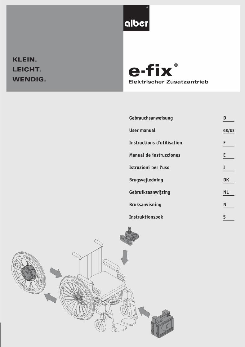
Die wichtigsten Elemente auf einen Blick(Hierzu bitte die Übersichtszeichnung der Umschlagseite ausklappen)
Rad/Bleche Bedienplatte 1Kupplungsring 2Steckachse 3Stecker 4Radaufnahme 5Drehmomentaufnahme 6
Akku Akku-Pack 7Akku-Tasche 8Klettverschluss 9Aussparung am Akku-Pack 10Ladebuchse 11Abdeckklappe 12Sicherung 3 A 13Sicherung 25 A 14Schnittstelle 15 Ladegerät Stecker 17
Bediengerät Bediengerät gesamt 18Ein/Aus Taste 19Display 20Stecker 21Buchse 22Stellrad für Geschwindigkeitsvorwahl 23Hupe 24Funktionstaste 25Joystick 26
Halterung (Fahrer)Verbindungsrohr 27Aufnahme 28Verschiebeteil 29Klemmhebel 30
Halterung (Begleitperson) Klemmhebel 32a/b
Aufnahme 33Aufnahmewinkel 34Befestigung am Rollstuhl 35
Schwenkarm Schwenkarm gesamt 36Kappe 37
Kippstützen Sicherungsstift 40Halterung 41Kippstütze 44
Rollstuhl Feststellbremsen 45Sichtfenster 46
Umschlag_alle_Sprachen.indd 1 10.07.2008 12:35:49 Uhr
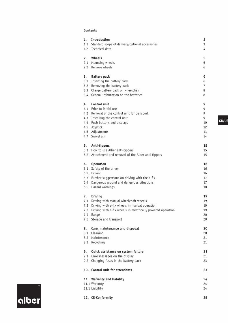
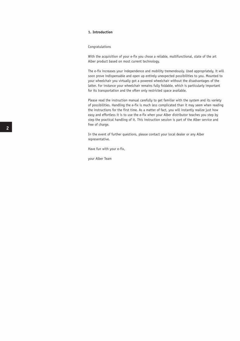
Overview of coupling ring
Release cover in the middle of the wheel is pressed in and “X” is displayed in the window:Wheel can be attached or removed
Release cover is flush with the coupling ring and “1” is displayed in the window:Wheel is ready for operation “Power driven“ mode
Release cover protrudes beyond the coupling ring and “0” is displayed in the window:Wheel is in “free-wheeling“
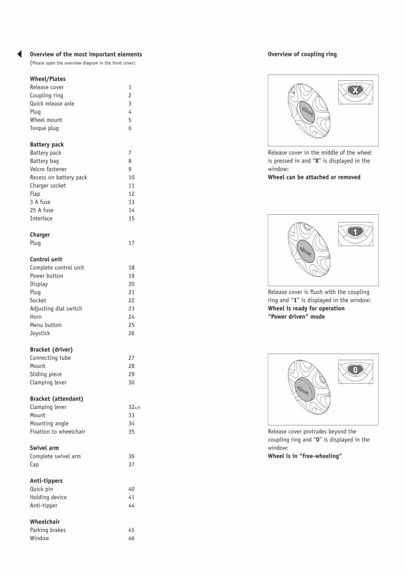
Overview of the most important elements(Please open the overview diagram in the front cover)
Wheel/Plates Release cover 1Coupling ring 2Quick release axle 3Plug 4Wheel mount 5Torque plug 6
Battery pack Battery pack 7Battery bag 8Velcro fastener 9Recess on battery pack 10Charger socket 11Flap 123 A fuse 1325 A fuse 14Interface 15 Charger Plug 17
Control unit Complete control unit 18Power button 19Display 20Plug 21Socket 22Adjusting dial switch 23Horn 24Menu button 25Joystick 26
Bracket (driver)Connecting tube 27Mount 28Sliding piece 29Clamping lever 30
Bracket (attendant) Clamping lever 32a/b
Mount 33Mounting angle 34Fixation to wheelchair 35
Swivel arm Complete swivel arm 36Cap 37
Anti-tippers Quick pin 40Holding device 41Anti-tipper 44
Wheelchair Parking brakes 45Window 46
BDA_E25_innen_GB_USA_final.indd 1 10.07.2008 12:06:52 Uhr
Contents
1. Introduction 21.1 Standard scope of delivery/optional accessories 31.2 Technical data 4
2. Wheels 52.1 Mounting wheels 52.2 Remove wheels 6
3. Battery pack 63.1 Inserting the battery pack 63.2 Removing the battery pack 73.3 Charge battery pack on wheelchair 83.4 General information on the batteries 8
4. Control unit 94.1 Prior to initial use 94.2 Removal of the control unit for transport 94.3 Installing the control unit 94.4 Push buttons and displays 104.5 Joystick 124.6 Adjustments 134.7 Swivel arm 14
5. Anti-tippers 155.1 How to use Alber anti-tippers 155.2 Attachment and removal of the Alber anti-tippers 15
6. Operation 166.1 Safety of the driver 166.2 Driving 166.3 Further suggestions on driving with the e-fix 176.4 Dangerous ground and dangerous situations 176.5 Hazard warnings 18
7. Driving 197.1 Driving with manual wheelchair wheels 197.2 Driving with e-fix wheels in manual operation 197.3 Driving with e-fix wheels in electrically powered operation 197.4 Range 207.5 Storage and transport 20
8. Care, maintenance and disposal 208.1 Cleaning 208.2 Maintenance 218.3 Recycling 21
9. Quick assistance on system failure 219.1 Error messages on the display 219.2 Changing fuses in the battery pack 23
10. Control unit for attendants 23
11. Warranty and liability 2411.1 Warranty 2411.1 Liability 24
12. CE-Conformity 25
GB/US
BDA_E25_innen_GB_USA_final.indd 2 10.07.2008 12:06:53 Uhr
1. Introduction
Congratulations
With the acquisition of your e-fix you chose a reliable, multifunctional, state of the art Alber product based on most current technology.
The e-fix increases your independence and mobility tremendously. Used appropriately, it will soon prove indispensable and open up entirely unexpected possibilities to you. Mounted to your wheelchair you virtually got a powered wheelchair without the disadvantages of the latter. For instance your wheelchair remains fully foldable, which is particularly important for its transportation and the often only restricted space available.
Please read the instruction manual carefully to get familiar with the system and its variety of possibilities. Handling the e-fix is much less complicated than it may seem when reading the instructions for the first time. As a matter of fact, you will instantly realize just how easy and effortless it is to use the e-fix when your Alber distributor teaches you step by step the practical handling of it. This instruction session is part of the Alber service and free of charge.
In the event of further questions, please contact your local dealer or any Alber representative.
Have fun with your e-fix,
your Alber Team
2
BDA_E25_innen_GB_USA_final.indd 3 10.07.2008 12:06:53 Uhr
Important safety instructions - Please observe them closely!
In the interest of your safety, the e-fix may only be operated by people who:
· have been taught how to use the e-fix
· are physically and mentally capable to use the e-fix in all possible situations of employment
The instruction session is part of the delivery package. It takes place by appointment and is done by your local dealer or one of the Alber distributors, no extra charge involved.
If for some reason you still do not feel comfortable handling the e-fix, please contact your local dealer.
Please also observe the maximum slope your wheelchair can handle determined by the wheelchair manufacturer. Do not exceed it.
The efficiency of the additional drive may be affected by electromagnetic fields, generated for example, by mobile telephones. The add-on drive therefore, should be switched off on safe ground. Also travel close to strong electric interference fields should be avoided.
The add-on drive can also affect other equipment such as theft-proof cabinets in departmental stores.
Do not use the e-fix before you participated in the instruction session.
1.1 Standard scope of delivery
· Quick-release axles drive wheels, 2 pieces· Control unit with bracket· Battery pack with bag· Charger· Interface with cable harness· Hand rest for control unit
Optional accessories
· Drive wheel for wheelchair users weighing max. 160 kg· Anti-tippers with jack-up function· Swivel arm for control unit · Bracket for attendant control · Opti-Box for connecting additional functions· Remote power button· Remote charging socket · Various joystick options· Large battery pack for increased capacity· Extended hand rest · Protection bow for the hand and the control unit· Tray table· Spoke cover· Intuitive attendant control · Control for engaging/disengaging the drive wheel
The accessories contained in this list and additional accessories can be found in the order lists and catalogues. For further information, please contact your dealer.
3
BDA_E25_innen_GB_USA_final.indd 4 10.07.2008 12:06:53 Uhr
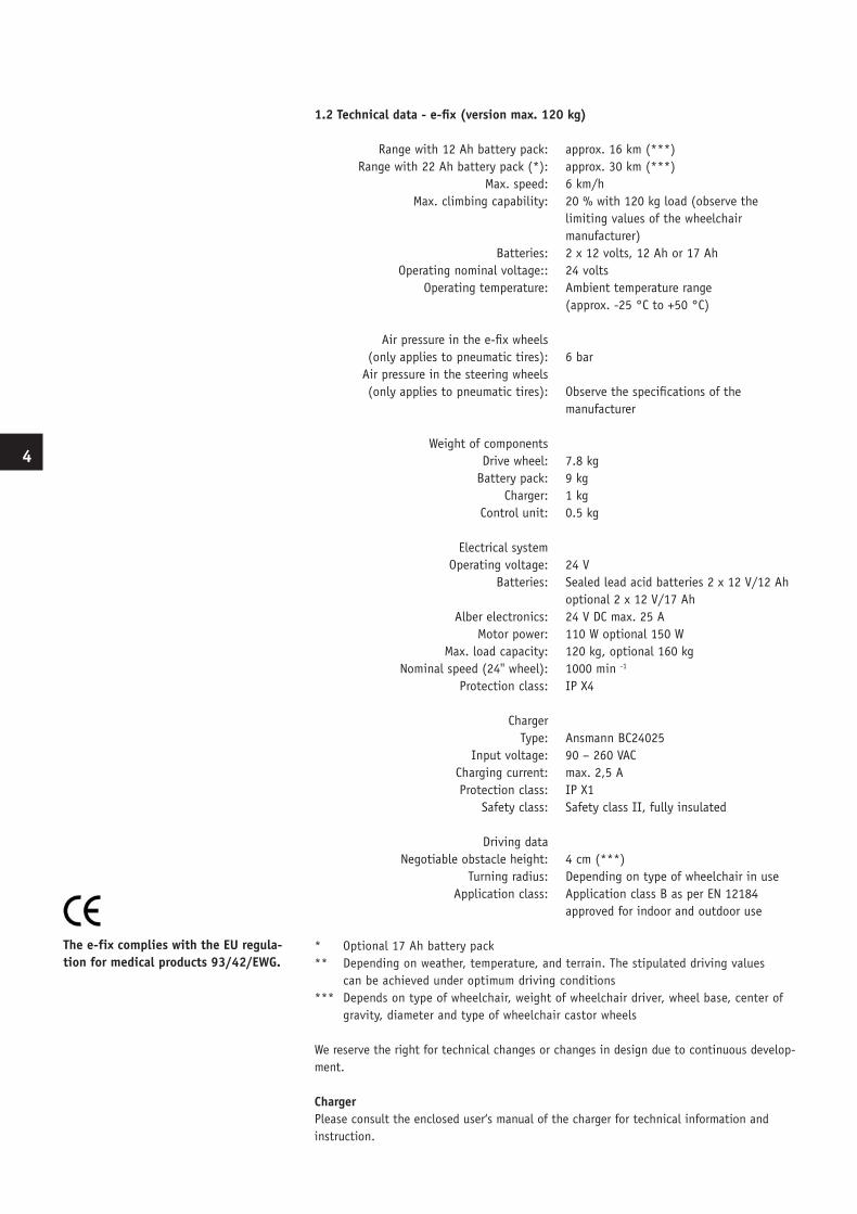
1.2 Technical data - e-fix (version max. 120 kg) Range with 12 Ah battery pack: approx. 16 km (***) Range with 22 Ah battery pack (*): approx. 30 km (***) Max. speed: 6 km/h Max. climbing capability: 20 % with 120 kg load (observe the limiting values of the wheelchair manufacturer) Batteries: 2 x 12 volts, 12 Ah or 17 Ah Operating nominal voltage:: 24 volts Operating temperature: Ambient temperature range (approx. -25 °C to +50 °C)
Air pressure in the e-fix wheels (only applies to pneumatic tires): 6 bar Air pressure in the steering wheels (only applies to pneumatic tires): Observe the specifications of the manufacturer
Weight of components Drive wheel: 7.8 kg Battery pack: 9 kg Charger: 1 kg Control unit: 0.5 kg
Electrical system Operating voltage: 24 V Batteries: Sealed lead acid batteries 2 x 12 V/12 Ah optional 2 x 12 V/17 Ah Alber electronics: 24 V DC max. 25 A Motor power: 110 W optional 150 W Max. load capacity: 120 kg, optional 160 kg Nominal speed (24'' wheel): 1000 min -1
Protection class: IP X4
Charger Type: Ansmann BC24025 Input voltage: 90 – 260 VAC Charging current: max. 2,5 A Protection class: IP X1 Safety class: Safety class II, fully insulated
Driving data Negotiable obstacle height: 4 cm (***) Turning radius: Depending on type of wheelchair in use Application class: Application class B as per EN 12184 approved for indoor and outdoor use
* Optional 17 Ah battery pack** Depending on weather, temperature, and terrain. The stipulated driving values can be achieved under optimum driving conditions *** Depends on type of wheelchair, weight of wheelchair driver, wheel base, center of gravity, diameter and type of wheelchair castor wheels
We reserve the right for technical changes or changes in design due to continuous develop-ment.
ChargerPlease consult the enclosed user‘s manual of the charger for technical information and instruction.
The e-fix complies with the EU regula-tion for medical products 93/42/EWG.
4
BDA_E25_innen_GB_USA_final.indd 5 10.07.2008 12:06:54 Uhr
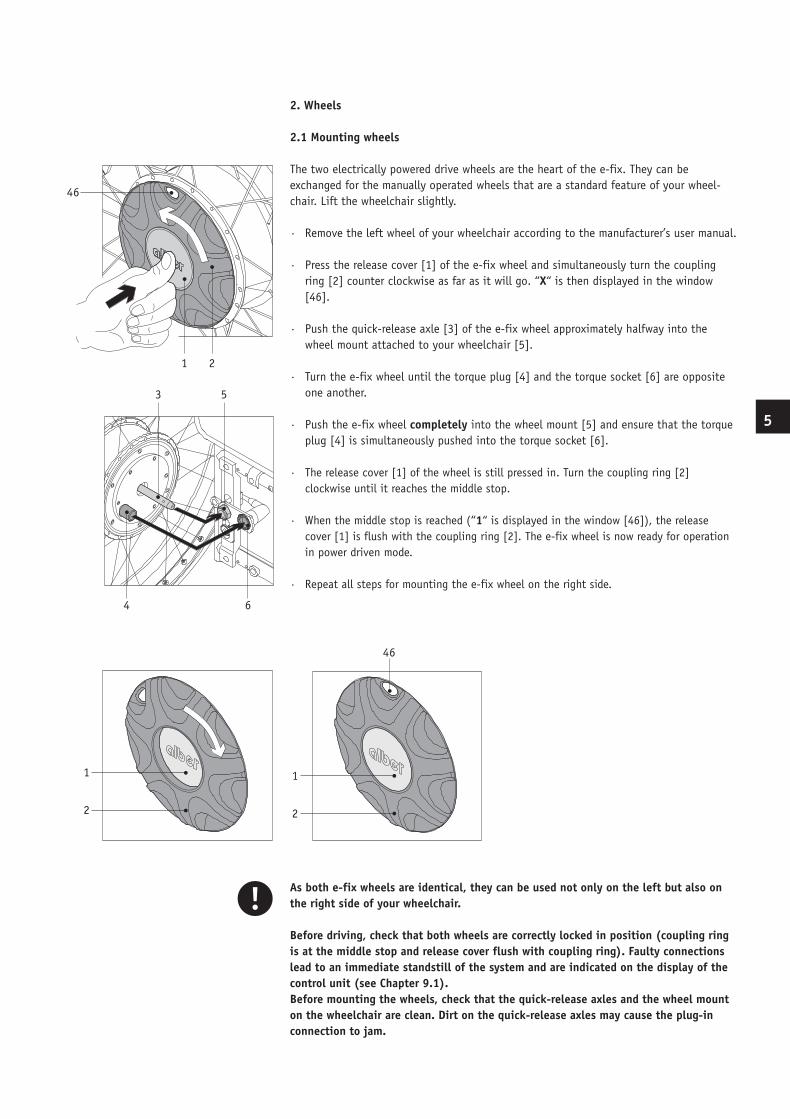
2. Wheels
2.1 Mounting wheels
The two electrically powered drive wheels are the heart of the e-fix. They can be exchanged for the manually operated wheels that are a standard feature of your wheel-chair. Lift the wheelchair slightly.
· Remove the left wheel of your wheelchair according to the manufacturer’s user manual.
· Press the release cover [1] of the e-fix wheel and simultaneously turn the coupling ring [2] counter clockwise as far as it will go. “X“ is then displayed in the window [46].
· Push the quick-release axle [3] of the e-fix wheel approximately halfway into the wheel mount attached to your wheelchair [5].
· Turn the e-fix wheel until the torque plug [4] and the torque socket [6] are opposite one another.
· Push the e-fix wheel completely into the wheel mount [5] and ensure that the torque plug [4] is simultaneously pushed into the torque socket [6].
· The release cover [1] of the wheel is still pressed in. Turn the coupling ring [2] clockwise until it reaches the middle stop.
· When the middle stop is reached (“1“ is displayed in the window [46]), the release cover [1] is flush with the coupling ring [2]. The e-fix wheel is now ready for operation in power driven mode.
· Repeat all steps for mounting the e-fix wheel on the right side.
As both e-fix wheels are identical, they can be used not only on the left but also on the right side of your wheelchair.
Before driving, check that both wheels are correctly locked in position (coupling ring is at the middle stop and release cover flush with coupling ring). Faulty connections lead to an immediate standstill of the system and are indicated on the display of the control unit (see Chapter 9.1).Before mounting the wheels, check that the quick-release axles and the wheel mount on the wheelchair are clean. Dirt on the quick-release axles may cause the plug-in connection to jam.
46
1 2
4 6
3 5
1
2
1
2
46
5
BDA_E25_innen_GB_USA_final.indd 6 10.07.2008 12:06:54 Uhr
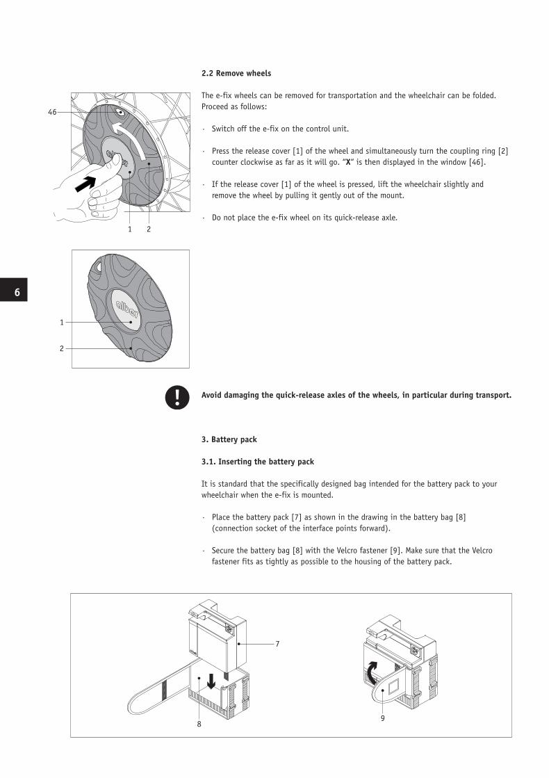
2.2 Remove wheels
The e-fix wheels can be removed for transportation and the wheelchair can be folded. Proceed as follows:
· Switch off the e-fix on the control unit.
· Press the release cover [1] of the wheel and simultaneously turn the coupling ring [2] counter clockwise as far as it will go. “X“ is then displayed in the window [46].
· If the release cover [1] of the wheel is pressed, lift the wheelchair slightly and remove the wheel by pulling it gently out of the mount.
· Do not place the e-fix wheel on its quick-release axle.
Avoid damaging the quick-release axles of the wheels, in particular during transport.
3. Battery pack
3.1. Inserting the battery pack
It is standard that the specifically designed bag intended for the battery pack to your wheelchair when the e-fix is mounted.
· Place the battery pack [7] as shown in the drawing in the battery bag [8] (con nection socket of the interface points forward).
· Secure the battery bag [8] with the Velcro fastener [9]. Make sure that the Velcro fastener fits as tightly as possible to the housing of the battery pack.
1 2
46
1
2
7
8 9
15
10
7
15
7
8 9
15
10
7
15
6
BDA_E25_innen_GB_USA_final.indd 7 10.07.2008 12:06:55 Uhr
8
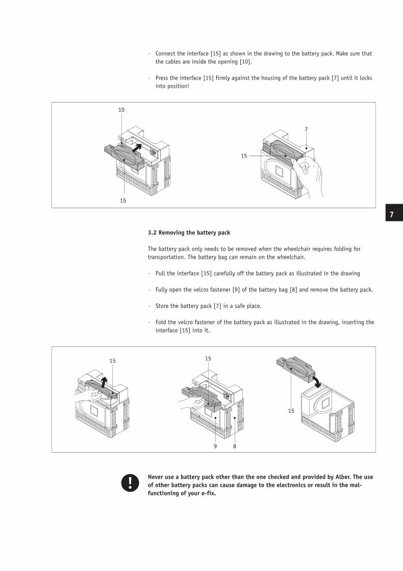
· Connect the interface [15] as shown in the drawing to the battery pack. Make sure that the cables are inside the opening [10].
· Press the interface [15] firmly against the housing of the battery pack [7] until it locks into position!
3.2 Removing the battery pack
The battery pack only needs to be removed when the wheelchair requires folding for transportation. The battery bag can remain on the wheelchair.
· Pull the interface [15] carefully off the battery pack as illustrated in the drawing
· Fully open the velcro fastener [9] of the battery bag [8] and remove the battery pack.
· Store the battery pack [7] in a safe place.
· Fold the velcro fastener of the battery pack as illustrated in the drawing, inserting the interface [15] into it.
Never use a battery pack other than the one checked and provided by Alber. The use of other battery packs can cause damage to the electronics or result in the mal-functioning of your e-fix.
7
8 9
15
10
7
15
15
15
15
89
15
15
15
89
15
15
15
89
7
8 9
15
10
7
15
7
BDA_E25_innen_GB_USA_final.indd 8 10.07.2008 12:06:56 Uhr
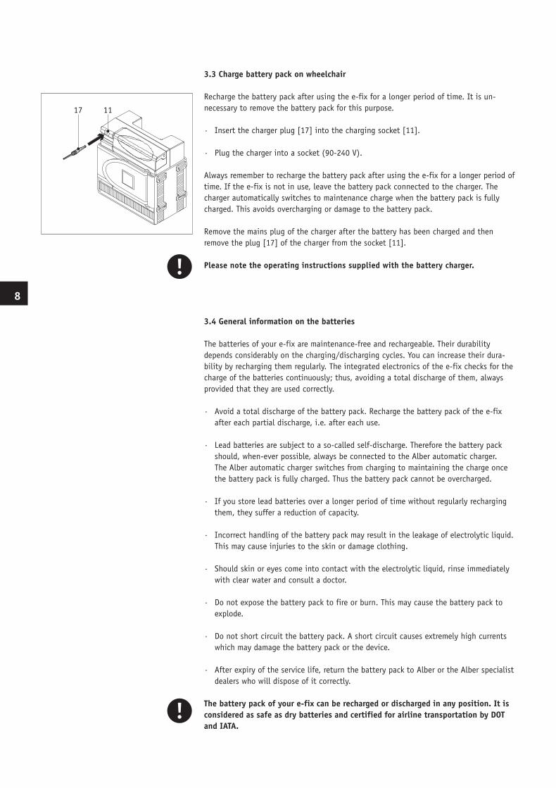
3.3 Charge battery pack on wheelchair
Recharge the battery pack after using the e-fix for a longer period of time. It is un-necessary to remove the battery pack for this purpose.
· Insert the charger plug [17] into the charging socket [11].
· Plug the charger into a socket (90-240 V).
Always remember to recharge the battery pack after using the e-fix for a longer period of time. If the e-fix is not in use, leave the battery pack connected to the charger. The charger automatically switches to maintenance charge when the battery pack is fully charged. This avoids overcharging or damage to the battery pack.
Remove the mains plug of the charger after the battery has been charged and then remove the plug [17] of the charger from the socket [11].
Please note the operating instructions supplied with the battery charger.
3.4 General information on the batteries
The batteries of your e-fix are maintenance-free and rechargeable. Their durability depends considerably on the charging/discharging cycles. You can increase their dura-bility by recharging them regularly. The integrated electronics of the e-fix checks for the charge of the batteries continuously; thus, avoiding a total discharge of them, always provided that they are used correctly.
· Avoid a total discharge of the battery pack. Recharge the battery pack of the e-fix after each partial discharge, i.e. after each use.
· Lead batteries are subject to a so-called self-discharge. Therefore the battery pack should, when-ever possible, always be connected to the Alber automatic charger. The Alber automatic charger switches from charging to maintaining the charge once the battery pack is fully charged. Thus the battery pack cannot be overcharged.
· If you store lead batteries over a longer period of time without regularly recharging them, they suffer a reduction of capacity.
· Incorrect handling of the battery pack may result in the leakage of electrolytic liquid. This may cause injuries to the skin or damage clothing.
· Should skin or eyes come into contact with the electrolytic liquid, rinse immediately with clear water and consult a doctor.
· Do not expose the battery pack to fire or burn. This may cause the battery pack to explode.
· Do not short circuit the battery pack. A short circuit causes extremely high currents which may damage the battery pack or the device.
· After expiry of the service life, return the battery pack to Alber or the Alber specialist dealers who will dispose of it correctly.
The battery pack of your e-fix can be recharged or discharged in any position. It is considered as safe as dry batteries and certified for airline transportation by DOT and IATA.
1117
8
BDA_E25_innen_GB_USA_final.indd 9 10.07.2008 12:06:57 Uhr
10
4. Control unit
4.1 Prior to initial use
The standard delivery package of the e-fix includes the mounting of its various components. It is, however, advisable to remove several components from the wheelchair, for instance, if you want to transport the wheelchair in a car. You gain more space or make better use of the existing space in your trunk.
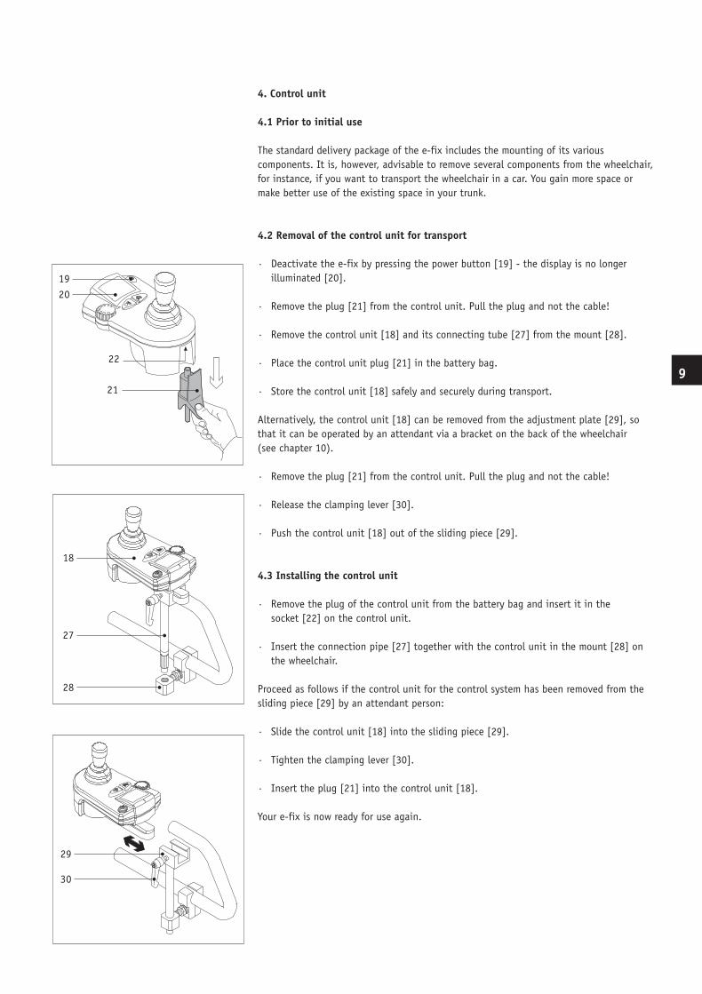
4.2 Removal of the control unit for transport
· Deactivate the e-fix by pressing the power button [19] - the display is no longer illuminated [20].
· Remove the plug [21] from the control unit. Pull the plug and not the cable!
· Remove the control unit [18] and its connecting tube [27] from the mount [28].
· Place the control unit plug [21] in the battery bag.
· Store the control unit [18] safely and securely during transport.
Alternatively, the control unit [18] can be removed from the adjustment plate [29], so that it can be operated by an attendant via a bracket on the back of the wheelchair (see chapter 10).
· Remove the plug [21] from the control unit. Pull the plug and not the cable!
· Release the clamping lever [30].
· Push the control unit [18] out of the sliding piece [29].
4.3 Installing the control unit
· Remove the plug of the control unit from the battery bag and insert it in the socket [22] on the control unit.
· Insert the connection pipe [27] together with the control unit in the mount [28] on the wheelchair.
Proceed as follows if the control unit for the control system has been removed from the sliding piece [29] by an attendant person:
· Slide the control unit [18] into the sliding piece [29].
· Tighten the clamping lever [30].
· Insert the plug [21] into the control unit [18].
Your e-fix is now ready for use again.
2019
21
22
28
27
18
30
29
9
BDA_E25_innen_GB_USA_final.indd 10 10.07.2008 12:06:58 Uhr
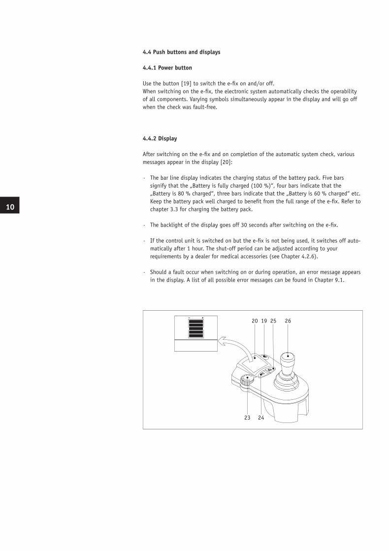
4.4 Push buttons and displays
4.4.1 Power button
Use the button [19] to switch the e-fix on and/or off. When switching on the e-fix, the electronic system automatically checks the operability of all components. Varying symbols simultaneously appear in the display and will go off when the check was fault-free.
4.4.2 Display
After switching on the e-fix and on completion of the automatic system check, various messages appear in the display [20]:
· The bar line display indicates the charging status of the battery pack. Five bars signify that the „Battery is fully charged (100 %)“, four bars indicate that the „Battery is 80 % charged“, three bars indicate that the „Battery is 60 % charged“ etc. Keep the battery pack well charged to benefit from the full range of the e-fix. Refer to chapter 3.3 for charging the battery pack.
· The backlight of the display goes off 30 seconds after switching on the e-fix.
· If the control unit is switched on but the e-fix is not being used, it switches off auto- matically after 1 hour. The shut-off period can be adjusted according to your requirements by a dealer for medical accessories (see Chapter 4.2.6).
· Should a fault occur when switching on or during operation, an error message appears in the display. A list of all possible error messages can be found in Chapter 9.1.
26251920
23 24
10
BDA_E25_innen_GB_USA_final.indd 11 10.07.2008 12:06:58 Uhr
12
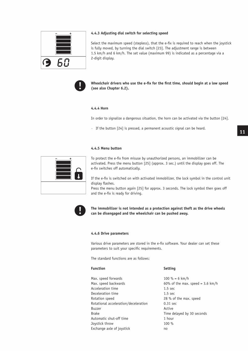
4.4.3 Adjusting dial switch for selecting speed
Select the maximum speed (stepless), that the e-fix is required to reach when the joystick is fully moved, by turning the dial switch [23]. The adjustment range is between 1.5 km/h and 6 km/h. The set value (maximum 99) is indicated as a percentage via a 2-digit display.
Wheelchair drivers who use the e-fix for the first time, should begin at a low speed (see also Chapter 6.2).
4.4.4 Horn
In order to signalize a dangerous situation, the horn can be activated via the button [24].
· If the button [24] is pressed, a permanent acoustic signal can be heard.
4.4.5 Menu button
To protect the e-fix from misuse by unauthorized persons, an immobilizer can be activated. Press the menu button [25] (approx. 3 sec.) until the display goes off. The e-fix switches off automatically. If the e-fix is switched on with activated immobilizer, the lock symbol in the control unit display flashes. Press the menu button again [25] for approx. 3 seconds. The lock symbol then goes off and the e-fix is ready for driving.
The immobilizer is not intended as a protection against theft as the drive wheels can be disengaged and the wheelchair can be pushed away.
4.4.6 Drive parameters
Various drive parameters are stored in the e-fix software. Your dealer can set these parameters to suit your specific requirements.
The standard functions are as follows:
11
Function
Max. speed forwardsMax. speed backwardsAcceleration timeDeceleration timeRotation speedRotational acceleration/decelerationBuzzerBrakeAutomatic shut-off timeJoystick throwExchange axle of joystick
Setting
100 % = 6 km/h60% of the max. speed = 3.6 km/h1.5 sec1.5 sec28 % of the max. speed0.31 secActiveTime delayed by 30 seconds1 hour100 %no
BDA_E25_innen_GB_USA_final.indd 12 10.07.2008 12:06:58 Uhr
Significance:
· Maximum speed forwards - the maximum speed that can be reached when the joystick is pushed forward as far as it will go.
· Maximum speed backwards - the maximum speed that can be reached when the joystick is pushed backward as far as it will go.
· Acceleration time - the time (duration) required for accelerating from a standstill or driving speed to the preset maximum speed.
· Deceleration time - the time (duration) of the braking procedure from the maximum speed to the desired power stage or standstill. This time (duration) depends to a great extent on the wheelchair settings.
· Rotation speed - maximum speed for driving in a circle/curve.
· Rotational acceleration/deceleration - duration of acceleration or delay when driving in a circle.
· Buzzer - Activation or deactivation of the acoustical signal.
· Brake - the time after issuing the last command until the electromagnetic brakes are activated.
· Automatic shut-off time - the time (duration) in which the e-fix remains ready to operate without switching off automatically for the purpose of saving energy.
· Joystick throw - the maximum necessary movement of the joystick to activate a drive command.
· Exchange axle of joystick - change directions of movement defined at the joystick.
Please contact your dealer for the individual adaptation of your functions. He will be pleased to advise you and program your settings.
4.5 Joystick
The joystick of the e-fix can be compared to a fictional combination of steering wheel, clutch and gas pedal of a car. Basically all of the wheelchair driver‘s control commands are directed to the e-fix wheels by the joystick. That‘s why driving the e-fix takes some practice. Please use the lowest speed when you drive the e-fix the first couple of times.
12
BDA_E25_innen_GB_USA_final.indd 13 10.07.2008 12:06:59 Uhr
14
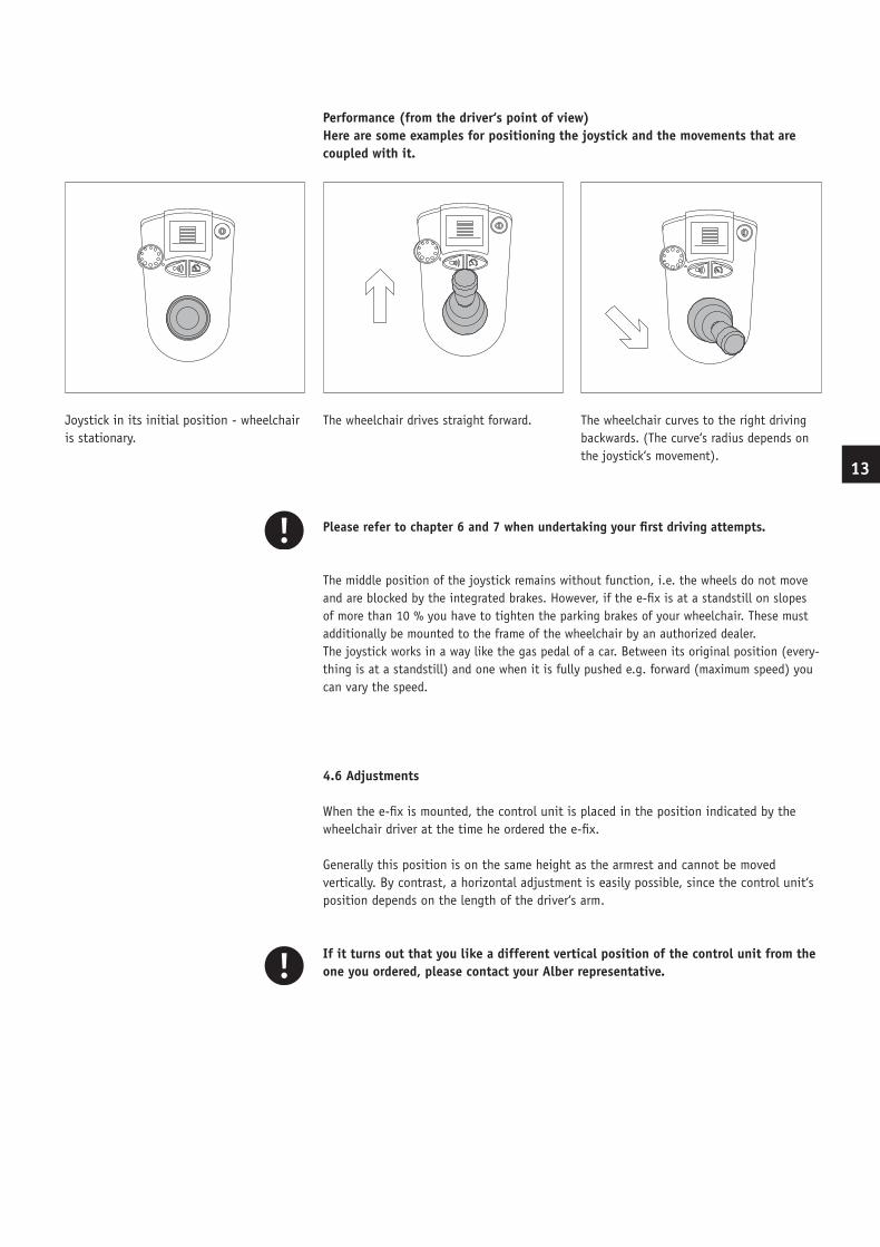
Joystick in its initial position - wheelchair is stationary.
Please refer to chapter 6 and 7 when undertaking your first driving attempts.
The middle position of the joystick remains without function, i.e. the wheels do not move and are blocked by the integrated brakes. However, if the e-fix is at a standstill on slopes of more than 10 % you have to tighten the parking brakes of your wheelchair. These must additionally be mounted to the frame of the wheelchair by an authorized dealer.The joystick works in a way like the gas pedal of a car. Between its original position (every-thing is at a standstill) and one when it is fully pushed e.g. forward (maximum speed) you can vary the speed.
4.6 Adjustments
When the e-fix is mounted, the control unit is placed in the position indicated by the wheelchair driver at the time he ordered the e-fix.
Generally this position is on the same height as the armrest and cannot be moved vertically. By contrast, a horizontal adjustment is easily possible, since the control unit‘s position depends on the length of the driver‘s arm.
If it turns out that you like a different vertical position of the control unit from the one you ordered, please contact your Alber representative.
The wheelchair drives straight forward. The wheelchair curves to the right driving backwards. (The curve‘s radius depends on the joystick‘s movement).
13
Performance (from the driver‘s point of view)Here are some examples for positioning the joystick and the movements that are coupled with it.
BDA_E25_innen_GB_USA_final.indd 14 10.07.2008 12:07:00 Uhr
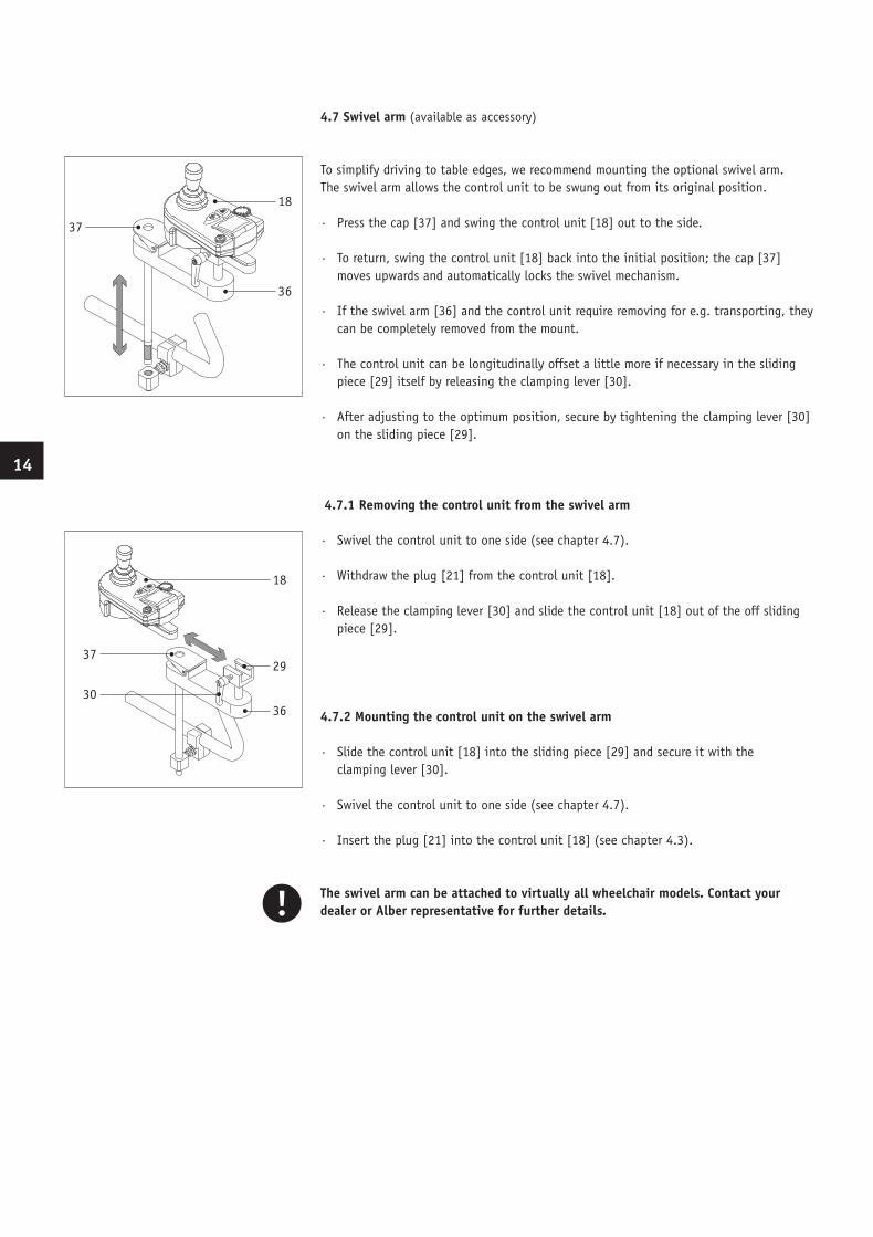
4.7 Swivel arm (available as accessory)
To simplify driving to table edges, we recommend mounting the optional swivel arm. The swivel arm allows the control unit to be swung out from its original position.
· Press the cap [37] and swing the control unit [18] out to the side.
· To return, swing the control unit [18] back into the initial position; the cap [37] moves upwards and automatically locks the swivel mechanism.
· If the swivel arm [36] and the control unit require removing for e.g. transporting, they can be completely removed from the mount.
· The control unit can be longitudinally offset a little more if necessary in the sliding piece [29] itself by releasing the clamping lever [30].
· After adjusting to the optimum position, secure by tightening the clamping lever [30] on the sliding piece [29].
4.7.1 Removing the control unit from the swivel arm
· Swivel the control unit to one side (see chapter 4.7).
· Withdraw the plug [21] from the control unit [18].
· Release the clamping lever [30] and slide the control unit [18] out of the off sliding piece [29].
4.7.2 Mounting the control unit on the swivel arm
· Slide the control unit [18] into the sliding piece [29] and secure it with the clamping lever [30].
· Swivel the control unit to one side (see chapter 4.7).
· Insert the plug [21] into the control unit [18] (see chapter 4.3).
The swivel arm can be attached to virtually all wheelchair models. Contact your dealer or Alber representative for further details.
37
18
36
30
18
29
36
37
14
BDA_E25_innen_GB_USA_final.indd 15 10.07.2008 12:07:00 Uhr
16
5. Anti-tippers (available as an accessory)
5.1 How to use Alber anti-tippers
Alber anti-tippers not only prevent the wheelchair from tipping but also assist the attendant when attaching and removing the manually-operated wheels and e-fix wheels. Proceed as follows:
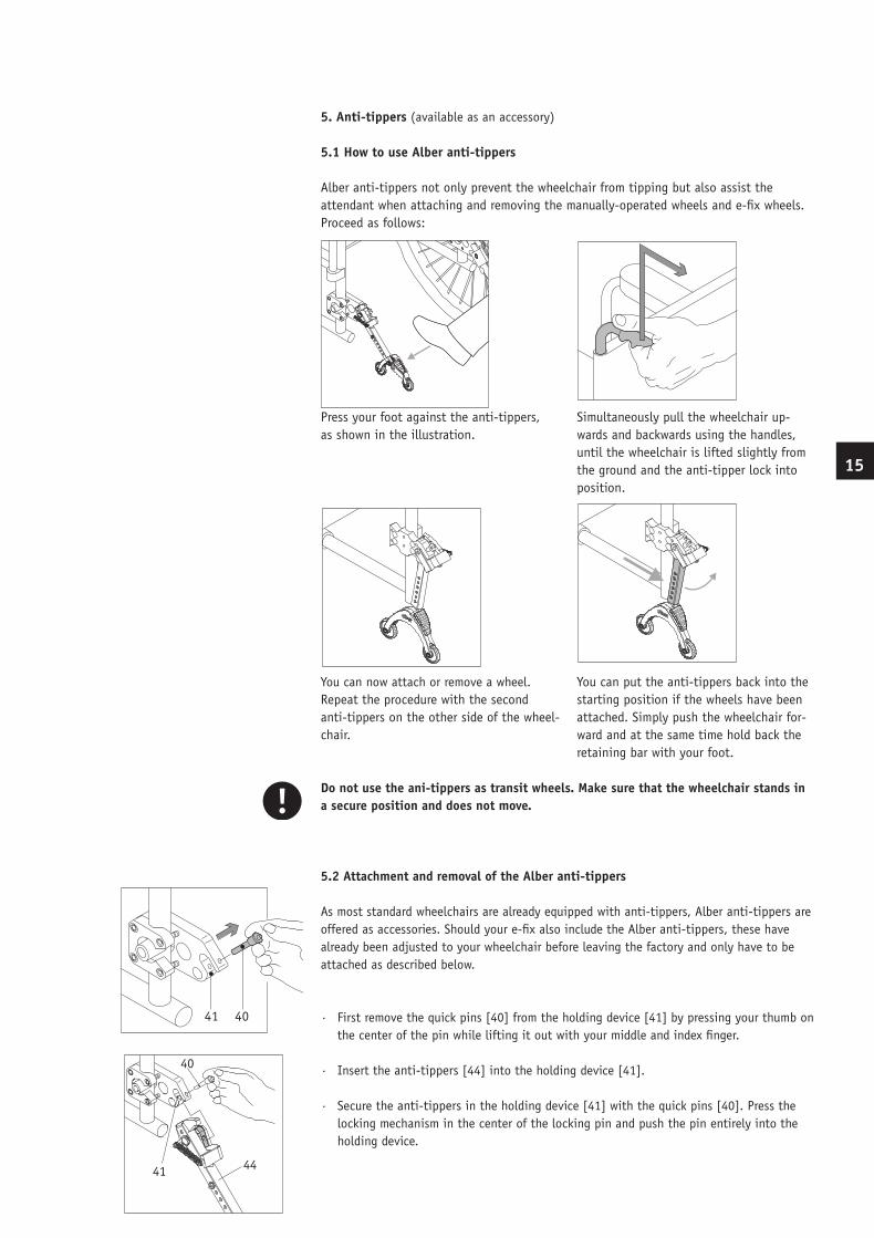
Press your foot against the anti-tippers, as shown in the illustration.
You can now attach or remove a wheel.Repeat the procedure with the second anti-tippers on the other side of the wheel-chair.
Do not use the ani-tippers as transit wheels. Make sure that the wheelchair stands in a secure position and does not move.
5.2 Attachment and removal of the Alber anti-tippers
As most standard wheelchairs are already equipped with anti-tippers, Alber anti-tippers are offered as accessories. Should your e-fix also include the Alber anti-tippers, these have already been adjusted to your wheelchair before leaving the factory and only have to be attached as described below.
· First remove the quick pins [40] from the holding device [41] by pressing your thumb on the center of the pin while lifting it out with your middle and index finger.
· Insert the anti-tippers [44] into the holding device [41].
· Secure the anti-tippers in the holding device [41] with the quick pins [40]. Press the locking mechanism in the center of the locking pin and push the pin entirely into the holding device.
41 40
41
40
39
41
40
Simultaneously pull the wheelchair up-wards and backwards using the handles, until the wheelchair is lifted slightly from the ground and the anti-tipper lock into position.
You can put the anti-tippers back into the starting position if the wheels have been attached. Simply push the wheelchair for-ward and at the same time hold back the retaining bar with your foot.
15
41
40
44
BDA_E25_innen_GB_USA_final.indd 16 10.07.2008 12:07:03 Uhr
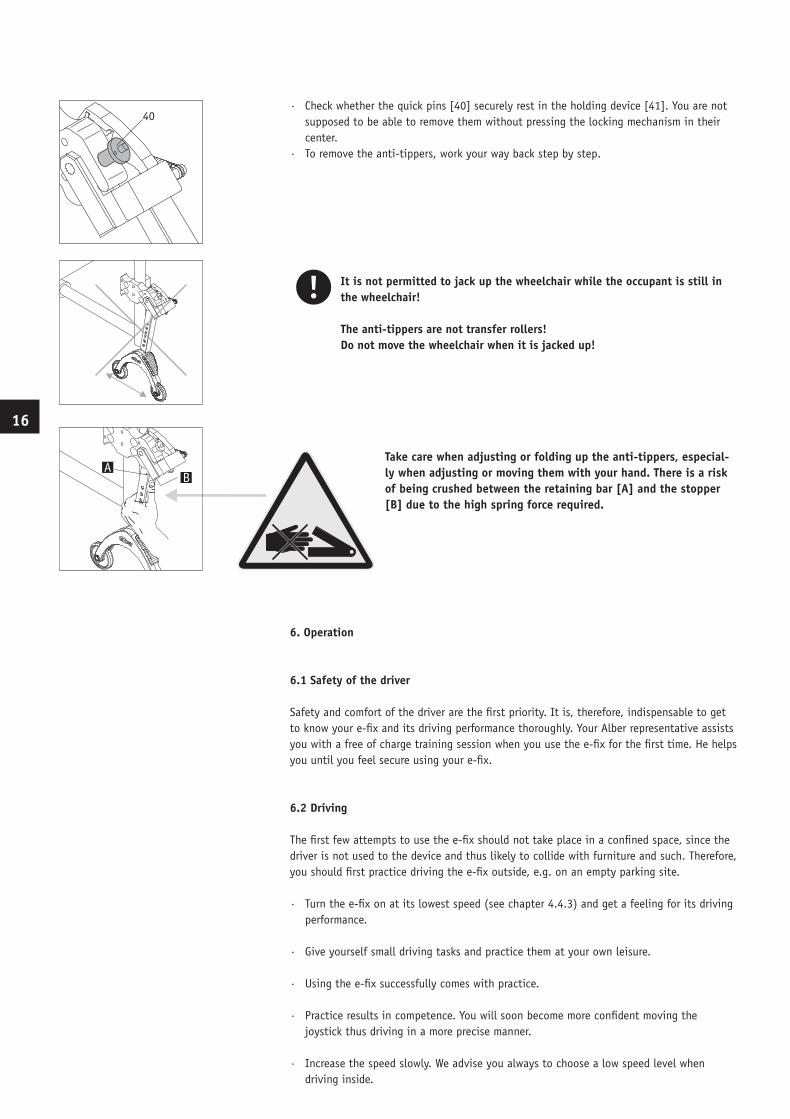
· Check whether the quick pins [40] securely rest in the holding device [41]. You are not supposed to be able to remove them without pressing the locking mechanism in their center.· To remove the anti-tippers, work your way back step by step.
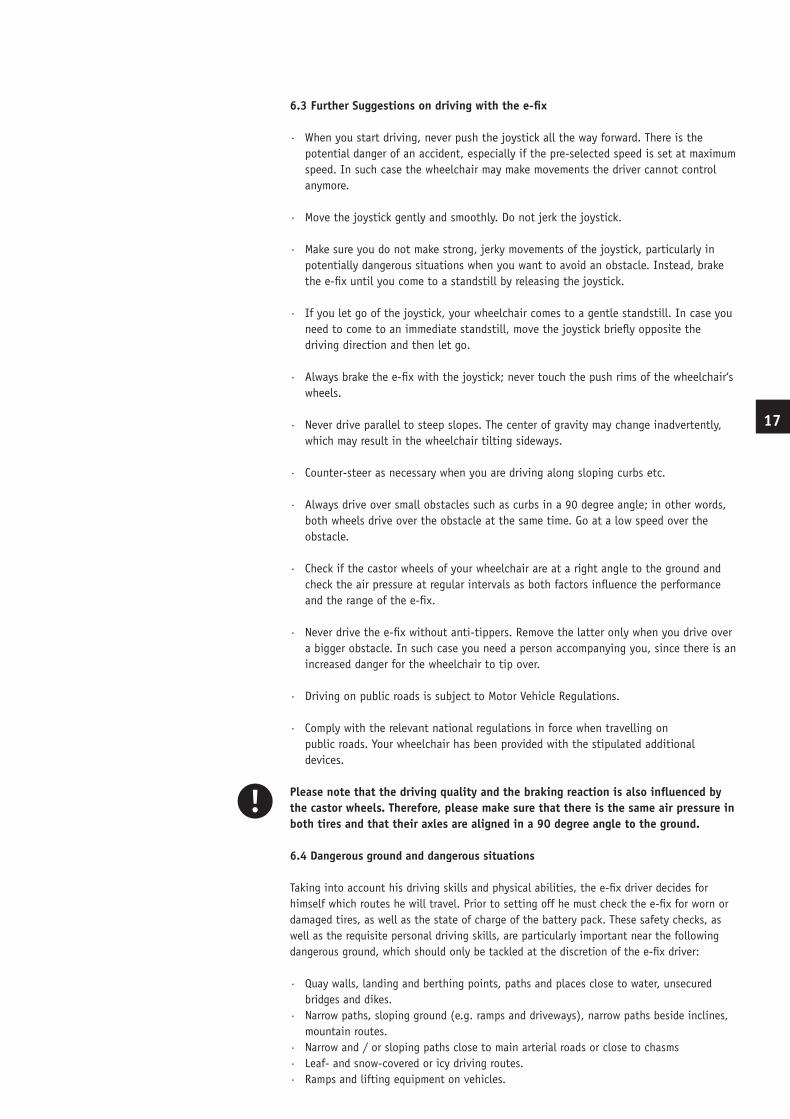
It is not permitted to jack up the wheelchair while the occupant is still in the wheelchair!
The anti-tippers are not transfer rollers!Do not move the wheelchair when it is jacked up!
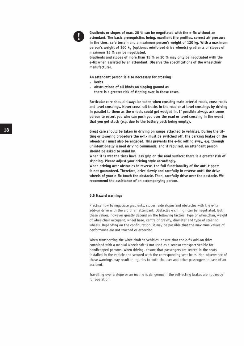
Take care when adjusting or folding up the anti-tippers, especial-ly when adjusting or moving them with your hand. There is a risk of being crushed between the retaining bar [A] and the stopper [B] due to the high spring force required.
6. Operation
6.1 Safety of the driver
Safety and comfort of the driver are the first priority. It is, therefore, indispensable to get to know your e-fix and its driving performance thoroughly. Your Alber representative assists you with a free of charge training session when you use the e-fix for the first time. He helps you until you feel secure using your e-fix.
6.2 Driving The first few attempts to use the e-fix should not take place in a confined space, since the driver is not used to the device and thus likely to collide with furniture and such. Therefore, you should first practice driving the e-fix outside, e.g. on an empty parking site.
· Turn the e-fix on at its lowest speed (see chapter 4.4.3) and get a feeling for its driving performance.
· Give yourself small driving tasks and practice them at your own leisure.
· Using the e-fix successfully comes with practice.
· Practice results in competence. You will soon become more confident moving the joystick thus driving in a more precise manner.
· Increase the speed slowly. We advise you always to choose a low speed level when driving inside.
16
40
AB
BDA_E25_innen_GB_USA_final.indd 17 10.07.2008 12:07:04 Uhr
18
6.3 Further Suggestions on driving with the e-fix
· When you start driving, never push the joystick all the way forward. There is the potential danger of an accident, especially if the pre-selected speed is set at maximum speed. In such case the wheelchair may make movements the driver cannot control anymore.
· Move the joystick gently and smoothly. Do not jerk the joystick.
· Make sure you do not make strong, jerky movements of the joystick, particularly in potentially dangerous situations when you want to avoid an obstacle. Instead, brake the e-fix until you come to a standstill by releasing the joystick.
· If you let go of the joystick, your wheelchair comes to a gentle standstill. In case you need to come to an immediate standstill, move the joystick briefly opposite the driving direction and then let go.
· Always brake the e-fix with the joystick; never touch the push rims of the wheelchair‘s wheels.
· Never drive parallel to steep slopes. The center of gravity may change inadvertently, which may result in the wheelchair tilting sideways.
· Counter-steer as necessary when you are driving along sloping curbs etc.
· Always drive over small obstacles such as curbs in a 90 degree angle; in other words, both wheels drive over the obstacle at the same time. Go at a low speed over the obstacle.
· Check if the castor wheels of your wheelchair are at a right angle to the ground and check the air pressure at regular intervals as both factors influence the performance and the range of the e-fix.
· Never drive the e-fix without anti-tippers. Remove the latter only when you drive over a bigger obstacle. In such case you need a person accompanying you, since there is an increased danger for the wheelchair to tip over.
· Driving on public roads is subject to Motor Vehicle Regulations.
· Comply with the relevant national regulations in force when travelling on public roads. Your wheelchair has been provided with the stipulated additional devices.
Please note that the driving quality and the braking reaction is also influenced by the castor wheels. Therefore, please make sure that there is the same air pressure in both tires and that their axles are aligned in a 90 degree angle to the ground.
6.4 Dangerous ground and dangerous situations
Taking into account his driving skills and physical abilities, the e-fix driver decides for himself which routes he will travel. Prior to setting off he must check the e-fix for worn or damaged tires, as well as the state of charge of the battery pack. These safety checks, as well as the requisite personal driving skills, are particularly important near the following dangerous ground, which should only be tackled at the discretion of the e-fix driver: · Quay walls, landing and berthing points, paths and places close to water, unsecured bridges and dikes.· Narrow paths, sloping ground (e.g. ramps and driveways), narrow paths beside inclines, mountain routes.· Narrow and / or sloping paths close to main arterial roads or close to chasms· Leaf- and snow-covered or icy driving routes.· Ramps and lifting equipment on vehicles.
17
BDA_E25_innen_GB_USA_final.indd 18 10.07.2008 12:07:05 Uhr
Gradients or slopes of max. 20 % can be negotiated with the e-fix without an attendant. The basic prerequisites being, excellent tire profiles, correct air pressure in the tires, safe terrain and a maximum person’s weight of 120 kg. With a maximum person’s weight of 160 kg (optional reinforced drive wheels) gradients or slopes of maximum 15 % can be negotiated.Gradients and slopes of more than 15 % or 20 % may only be negotiated with the e-fix when assisted by an attendant. Observe the specifications of the wheelchair manufacturer. An attendant person is also necessary for crossing· kerbs · obstructions of all kinds on sloping ground as there is a greater risk of tipping over in these cases.
Particular care should always be taken when crossing main arterial roads, cross roads and level crossings. Never cross rail tracks in the road or at level crossings by driving in parallel to them as the wheels could get wedged in. If possible always ask some person to escort you who can push you over the road or level crossing in the event that you get stuck (e.g. due to the battery pack being empty).
Great care should be taken in driving on ramps attached to vehicles. During the lif-ting or lowering procedure the e-fix must be switched off. The parking brakes on the wheelchair must also be engaged. This prevents the e-fix rolling away, e.g. through unintentionally issued driving commands; and if required, an attendant person should be asked to stand by. When it is wet the tires have less grip on the road surface; there is a greater risk of slipping. Please adjust your driving style accordingly. When driving over obstacles in reverse, the full functionality of the anti-tippers is not guaranteed. Therefore, drive slowly and carefully in reverse until the drive wheels of your e-fix touch the obstacle. Then, carefully drive over the obstacle. We recommend the assistance of an accompanying person.
6.5 Hazard warnings
Practise how to negotiate gradients, slopes, side slopes and obstacles with the e-fix add-on drive with the aid of an attendant. Obstacles 4 cm high can be negotiated. Both these values, however greatly depend on the following factors: Type of wheelchair, weight of wheelchair occupant, wheel base, centre of gravity, diameter and type of steering wheels. Depending on the configuration, it may be possible that the maximum values of performance are not reached or exceeded.
When transporting the wheelchair in vehicles, ensure that the e-fix add-on drive combined with a manual wheelchair is not used as a seat or transport vehicle forhandicapped persons. When driving, ensure that passengers are seated in the seats installed in the vehicle and secured with the corresponding seat belts. Non-observance of these warnings may result in injuries to both the user and other passengers in case of an accident.
Travelling over a slope or an incline is dangerous if the self-acting brakes are not ready for operation.
18
BDA_E25_innen_GB_USA_final.indd 19 10.07.2008 12:07:05 Uhr
20
7. Driving
7.1 Driving with manual wheelchair wheels
In chapter 2 you learned how to mount the e-fix wheels to and remove them from your wheelchair. So you have the choice to use the conventional wheels that are manually propelled or the electrically powered e-fix wheels. The parking brakes attached to your wheelchair [45] are adjusted to the e-fix wheels. When operating your wheelchair with the conventional wheels, the parking brakes [45] may need readjusting!
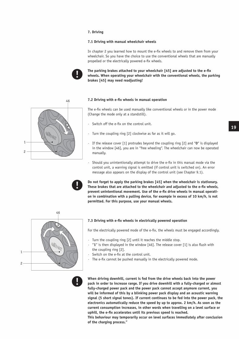
7.2 Driving with e-fix wheels in manual operation
The e-fix wheels can be used manually like conventional wheels or in the power mode (Change the mode only at a standstill).
· Switch off the e-fix on the control unit.
· Turn the coupling ring [2] clockwise as far as it will go.
· If the release cover [1] protrudes beyond the coupling ring [2] and “0“ is displayed in the window [46], you are in “free wheeling“. The wheelchair can now be operated manually.
· Should you unintentionally attempt to drive the e-fix in this manual mode via the control unit, a warning signal is emitted (if control unit is switched on). An error message also appears on the display of the control unit (see Chapter 9.1).
Do not forget to apply the parking brakes [45] when the wheelchair is stationary. These brakes that are attached to the wheelchair and adjusted to the e-fix wheels, prevent unintentional movement. Use of the e-fix drive wheels in manual operati-on in combination with a pulling device, for example in excess of 10 km/h, is not permitted. For this purpose, use your manual wheels.
7.3 Driving with e-fix wheels in electrically powered operation
For the electrically powered mode of the e-fix, the wheels must be engaged accordingly.
· Turn the coupling ring [2] until it reaches the middle stop.· “1“ is then displayed in the window [46]. The release cover [1] is also flush with the coupling ring [2].· Switch on the e-fix at the control unit.· The e-fix cannot be pushed manually in the electrically powered mode.
When driving downhill, current is fed from the drive wheels back into the power pack in order to increase range. If you drive downhill with a fully-charged or almost fully-charged power pack and the power pack cannot accept anymore current, you will be informed of this by a blinking power pack display and an acoustic warning signal (5 short signal tones). If current continues to be fed into the power pack, the electronics automatically reduce the speed by up to approx. 2 km/h. As soon as the current consumption increases, in other words when travelling on a level surface or uphill, the e-fix accelerates until its previous speed is reached.This behaviour may temporarily occur on level surfaces immediately after conclusion of the charging process.”
1
2
46
1
2
46
19
BDA_E25_innen_GB_USA_final.indd 20 10.07.2008 12:07:05 Uhr
7.4 Range
For every user of the e-fix, one of the most interesting questions is the range of the system. It can generally be assumed that a range of approx. 16 km can be reached with the standard battery pack (12 Ah), and a range of approx. 30 km with the 17 Ah battery pack. These are ideal values and are based on flat, firm terrain. Deviations are possible due to topographical conditions, ambient temperature, type of terrain, tire pressure of the front wheels, frame geometry, weight of the wheelchair, weight of the driver and type of drive wheels used.
7.5 Storage and transport
7.5.1 Storage
For long-term storage of your e-fix drive, store the e-fix wheels and especially the battery pack in a dry place, preferably at room temperature (15 °C to 25 °C). For storage purposes only, connect the battery pack every 2 months to the supplied charger andcharge it completely. This ensures that your e-fix add-on drive will function even after storing for a longer period of time. The batteries used are leakage-proof, maintenance free and dry cell batteries. Store the battery pack preferably upright (in the same position as they are in the wheelchair).Refer to Chapter 3.4 for further information on the type of batteries used.
7.5.2 Transport
Contrary to electric wheelchairs, you may still fold your wheelchair with the e-fix attached, i.e. you can transport it as easily as any manual wheelchair with no additional space required.
· Remove the control unit from the wheelchair (see Chapter 4.2).
· Remove the battery pack from the battery bag (see Chapter 3.2).
· Remove the wheels (see chapter 2.2).
· Fold your wheelchair and store it together with all its components.
· After transportation, reassemble your wheelchair by following these instructions in reversed order.
8. Care, maintenance and disposal
8.1 Cleaning
Control unit, wheels and battery may be cleaned with a damp (not wet) cloth rag. Use regular household cleaners in water diluted, never petroleum ether or the like. Do not rinse the wheels with a water hose.
Ensure that liquids are prevented from entering any components of e-fix.
20
BDA_E25_innen_GB_USA_final.indd 21 10.07.2008 12:07:06 Uhr
2221
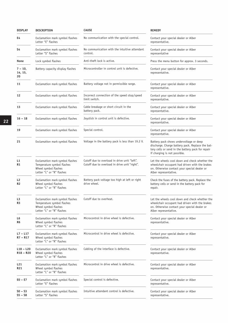
9.1 Error messages on the display
Symbol
Numeric code
8.2 Maintenance
Your e-fix wheelchair requires a minimum of maintenance. Nevertheless, we recommend checking regularly that all parts and accessories are securely fixed. In order to ensu-re that your Adventure wheelchair is safe to drive and functioning correctly, it should undergo a technical inspection every 2 years at the latest. In particular, damage that has occurred during use that is not visible to the naked eye as well as wear and fatigue can thus be detected.For this purpose, contact directly your authorized Alber dealer.
Service and repairs on the e-fix may only be carried out by authorized dealers. In case of defects, please contact your dealer.
8.3 Recycling
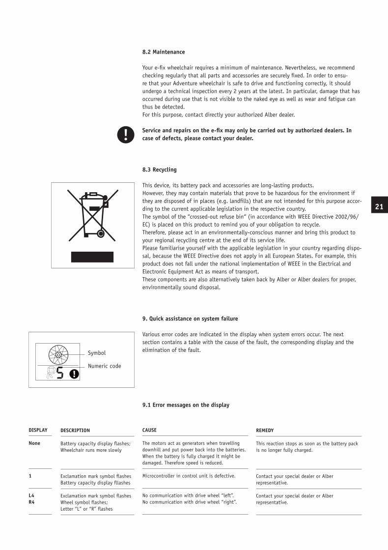
This device, its battery pack and accessories are long-lasting products. However, they may contain materials that prove to be hazardous for the environment if they are disposed of in places (e.g. landfills) that are not intended for this purpose accor-ding to the current applicable legislation in the respective country.The symbol of the “crossed-out refuse bin“ (in accordance with WEEE Directive 2002/96/EC) is placed on this product to remind you of your obligation to recycle.Therefore, please act in an environmentally-conscious manner and bring this product to your regional recycling centre at the end of its service life. Please familiarise yourself with the applicable legislation in your country regarding dispo-sal, because the WEEE Directive does not apply in all European States. For example, this product does not fall under the national implementation of WEEE in the Electrical and Electronic Equipment Act as means of transport.These components are also alternatively taken back by Alber or Alber dealers for proper, environmentally sound disposal.
9. Quick assistance on system failure
Various error codes are indicated in the display when system errors occur. The next section contains a table with the cause of the fault, the corresponding display and the elimination of the fault.
DESCRIPTION Battery capacity display flashes; Wheelchair runs more slowly
Exclamation mark symbol flashes Battery capacity display fllashes Exclamation mark symbol flashes Wheel symbol flashes; Letter “L” or “R” flashes
CAUSE The motors act as generators when travelling downhill and put power back into the batteries. When the battery is fully charged it might be damaged. Therefore speed is reduced. Microcontroller in control unit is defective.
No communication with drive wheel “left”. No communication with drive wheel “right”.
REMEDY This reaction stops as soon as the battery pack is no longer fully charged.
Contact your special dealer or Alber representative. Contact your special dealer or Alber representative.
DISPLAY None
1
L4 R4
BDA_E25_innen_GB_USA_final.indd 22 10.07.2008 12:07:06 Uhr
Exclamation mark symbol flashes
Exclamation mark symbol flashes
Exclamation mark symbol flashes
Exclamation mark symbol flashes
Exclamation mark symbol flashes
Exclamation mark symbol flashes
Exclamation mark symbol flashes Temperature symbol flashes Wheel symbol flashes Letter “L” or “R” flashes Exclamation mark symbol flashes Wheel symbol flashes Letter “L” or “R” flashes
Exclamation mark symbol flashes Temperature symbol flashes Wheel symbol flashes Letter “L” or “R” flashes Exclamation mark symbol flashes Wheel symbol flashes Letter “L” or “R” flashes Exclamation mark symbol flashes Wheel symbol flashes Letter “L” or “R” flashes Exclamation mark symbol flashes Wheel symbol flashes Letter “L” or “R” flashes Exclamation mark symbol flashes Wheel symbol flashes Letter “L” or “R” flashes Exclamation mark symbol flashes Letter “E” flashes Exclamation mark symbol flashes Letter “S” flashes
Battery voltage not in permissible range.
Incorrect connection of the speed stop/speed limit switch. Cable breakage or short circuit in the battery pack. Joystick in control unit is defective.
Special control.
Voltage in the battery pack is less than 19.2 V.
Cutoff due to overload in drive unit “left”. Cutoff due to overload in drive unit “right”.
Battery pack voltage too high at left or right drive wheel.
Cutoff due to overheat.
Microcontrol in drive wheel is defective.
Microcontrol in drive wheel is defective.
Cabling of the interface is defective.
Microcontrol in drive wheel is defective.
Special control is defective.
Intuitive attendant control is defective.
Contact your special dealer or Alber representative. Contact your special dealer or Alber representative. Contact your special dealer or Alber representative. Contact your special dealer or Alber representative. Contact your special dealer or Alber representative. Battery pack shows undervoltage or deep discharge. Charge battery pack. Replace the bat-tery cells or send in the battery pack for repair if charging is not possible. Let the wheels cool down and check whether the wheelchair occupant had driven with the brakes on. Otherwise contact your special dealer or Alber representative. Check the fuses of the battery pack. Replace the battery cells or send in the battery pack for repair.
Let the wheels cool down and check whether the wheelchair occupant had driven with the brakes on. Otherwise contact your special dealer or Alber representative. Contact your special dealer or Alber representative.
Contact your special dealer or Alber representative.
Contact your special dealer or Alber representative.
Contact your special dealer or Alber representative.
Contact your special dealer or Alber representative. Contact your special dealer or Alber representative.
11
12
13 16 – 18
19
21
L1 R1
L2 R2
L3 R3
L6 R6
L7 – L17 R7 – R17
L18 – L20 R18 – R20
L21 R21
E0 – E7
S0 – S3 S5 – S8
22
DESCRIPTION
Exclamation mark symbol flashes Letter “E” flashes Exclamation mark symbol flashes Letter “S” flashes Lock symbol flashes Battery capacity display flashes
CAUSE No communication with the special control.
No communication with the intuitive attendant control. Anti-theft lock is active. Microcontroller in control unit is defective.
REMEDY Contact your special dealer or Alber representative. Contact your special dealer or Alber representative Press the menu button for approx. 3 seconds. Contact your special dealer or Alber representative.
DISPLAY E4
S4
None 7 – 10, 14, 15, 20
BDA_E25_innen_GB_USA_final.indd 23 10.07.2008 12:07:07 Uhr
2423
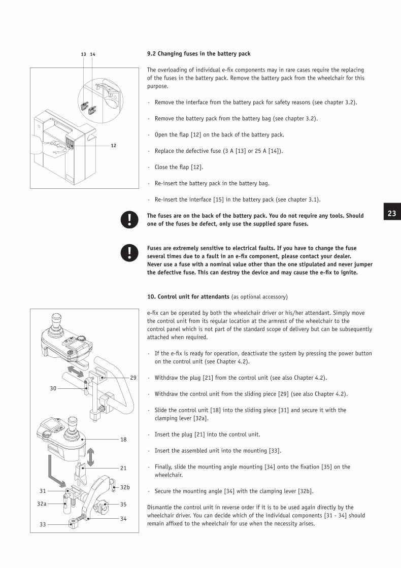
9.2 Changing fuses in the battery pack
The overloading of individual e-fix components may in rare cases require the replacing of the fuses in the battery pack. Remove the battery pack from the wheelchair for this purpose.
· Remove the interface from the battery pack for safety reasons (see chapter 3.2).
· Remove the battery pack from the battery bag (see chapter 3.2).
· Open the flap [12] on the back of the battery pack.
· Replace the defective fuse (3 A [13] or 25 A [14]).
· Close the flap [12].
· Re-insert the battery pack in the battery bag.
· Re-insert the interface [15] in the battery pack (see chapter 3.1).
The fuses are on the back of the battery pack. You do not require any tools. Should one of the fuses be defect, only use the supplied spare fuses.
Fuses are extremely sensitive to electrical faults. If you have to change the fuse several times due to a fault in an e-fix component, please contact your dealer.Never use a fuse with a nominal value other than the one stipulated and never jumper the defective fuse. This can destroy the device and may cause the e-fix to ignite.
10. Control unit for attendants (as optional accessory)
e-fix can be operated by both the wheelchair driver or his/her attendant. Simply move the control unit from its regular location at the armrest of the wheelchair to the control panel which is not part of the standard scope of delivery but can be subsequently attached when required.
· If the e-fix is ready for operation, deactivate the system by pressing the power button on the control unit (see Chapter 4.2).
· Withdraw the plug [21] from the control unit (see also Chapter 4.2).
· Withdraw the control unit from the sliding piece [29] (see also Chapter 4.2).
· Slide the control unit [18] into the sliding piece [31] and secure it with the clamping lever [32a].
· Insert the plug [21] into the control unit.
· Insert the assembled unit into the mounting [33].
· Finally, slide the mounting angle mounting [34] onto the fixation [35] on the wheelchair.
· Secure the mounting angle [34] with the clamping lever [32b].
Dismantle the control unit in reverse order if it is to be used again directly by the wheelchair driver. You can decide which of the individual components [31 - 34] should remain affixed to the wheelchair for use when the necessity arises.
12
13 14
30
29
31
21
32b
34
3532a
33
18
BDA_E25_innen_GB_USA_final.indd 24 10.07.2008 12:07:08 Uhr
11. Warranty and liability
11.1 Warranty
The time of warranty for the e-fix amounts to 24 months (12 months for the batteries) from the date of purchase, and covers faulty material and processing defects.The warranty does not include:
· natural wear and tear
· damage caused by improper use
· forced damage
· unauthorized changes made on the device and/or its accessories.
The operating noise of the drive motors may increase slightly on completion of the running-in period. This is not the result of wear on mechanical components and therefore, is not included in the durability guarantee.
In particular the General Standard Terms and Conditions of Ulrich Alber GmbH apply.
11.2 Liability
Neither Ulrich Alber GmbH nor its agents or authorized dealers and sales representatives will be liable for the safety, reliability or performance of the e-fix or for any claims for personal injury or property damage which may arise from the following:
· The e-fix was driven without anti-tippers.
· The e-fix was handled and used inappropriately.
· The e-fix was used other than in accordance with all instructions and precautions included in the operator‘s manual and on the product labeling.
· The e-fix was not checked every two years by an authorized dealer or Ulrich Alber GmbH.
· Assembly, repairs and other work was done by unauthorized personnel.
· Parts or accessories other than those recommended by Ulrich Alber GmbH were used.
· Parts of the e-fix were changed or removed entirely.
24
BDA_E25_innen_GB_USA_final.indd 25 10.07.2008 12:07:08 Uhr
12. CE conformity
The CE conformity for the e-fix is only valid in combination with the anti-tippers. In addition, the following points have to be taken into consideration:
· Assembly and repairs as well as any other work done on the e-fix must be carried out by Ulrich Alber GmbH or any other personnel authorized by Ulrich Alber GmbH.
· The lower part of the anti-tippers must be attached high enough so that their wheels can rotate freely when the wheelchair is on a horizontal level.
· The user must pay particular attention to the following: a) The anti-tippers must be unobstructed. b) Please be extra careful when driving over obstacles higher than 40 mm and narrower than the sidewalk‘s curb. c) The critical height of obstacles must be tested individually for each wheelchair equipped with the e-fix by the occupant. d) The point at which a certain wheelchair equipped with the e-fix tilts backwards at its back axle must also be tested by the occupant. The critical limit is reached at the point where the tilted wheelchair falls backwards.
Important safety note:Driving the e-fix without attached anti-tippers is not safe, thus not admissible.
25
BDA_E25_innen_GB_USA_final.indd 26 10.07.2008 12:07:08 Uhr

www.alber.de
Ulrich Alber GmbHVor dem Weißen Stein 2172461 AlbstadtTelefon +49 (0)7432 2006-0Telefax +49 (0)7432 [email protected]
Ihre Alber-Vertretung / Your Alber representative / Votre représentation Alber / Vostra rappresentanza Alber / Su representación Alber / Din Alber representant /Din Alber-agenturene / Uw distributeur Alber / Deres Alber-repræsentation
© Ulrich Alber GmbH, Albstadt
Umschlag_alle_Sprachen.indd 4 10.07.2008 12:35:51 Uhr