Embed Size (px)
Citation preview

Korjauskonseptien kestävyyden
näkökohtia ja suositukset
rakennusteollisuudelle
Tomi Toratti
VTT Technical Research Centre of Finland

2 02/05/2012
Reference publications
D2.2 Guidelines for the use of building physical modelling
methods and tools in the development of sustainable refurbishment
technologies for external walls.
D4.2 General renovation concepts – Durability
D7.2 Guidelines for building industry

3 02/05/2012
D2.2 Guidelines for the use of building physical modelling
methods and tools in the development of sustainable
refurbishment technologies for external walls.
Methods to calculate building physical performance of walls
- Thermal performance
- Moisture control
- Durability (mould)
- Indoor air
Use of WuFi program
Practical guideline on how to carry out the calculations
- Inputs
- Analysis of output
- State of art in mould models

4 02/05/2012
D4.2 General renovation concepts – Durability

5 02/05/2012
Service load
Dead loadClimatic stresses
Biological factors
Stresses of
building envelopes
29.9.2011 - v12
Wind
Bending
Cracks
Falling down
Snow
Bending
Cracks
Falling down
Thermal
expansion
Bending
Cracks
Falling down
Own weightBending
Supported
structuresBending
Cracks
Creep Bending
Cracks
ShrinkageBending
Cracks
UV-radiation
Fading
Degradation
Ageing
Wind
Bending
Cracks
Falling down
Rain
Mois ture accumulation
Mould
Rotting
Salt migration
Fros t damages
Corrosion
Snow
Bending
Cracks
Falling down
Indoor air moistureMois ture accumulation
Mould
Temperature changesBending
Cracks
Freeze - thaw
Disintegration
Loss of strength
Peeling off
Fros tCracks
Breakage
Carbon dioxideCarbonation
Air pollutantsCorrosion
MouldHealth risks
Aesthetic aspects
RottingLoss of strength
InsectsAesthetic aspects
Loss of strength
PestsAir leakages
Health risks

6 02/05/2012
Frost damage
Corrosion
Degradation
Carbonation
Overload
Wetting - drying
Freeze - thaw
Moisture
Temperature changes
Salt migration
Solar radiation
Fire
Deterioration
mechamisms
2.10.2011 - v33
Peeling offPainting
Rendering
Cracking
Concrete
Masonry
Fragile porous materials
Rus tingSteel
CorrosionMetals
Glass
CrackingPlas tics
BreakagePlas tics
Becoming fragilePolymers
Plas tics
Loss of strengthPolymers
Plas tics
CrackingPolymers
Plas tics
CorrosionSteel bars
CrackingConcrete
BendingCladding materials
Supporting s tructures
BreakageCladding materials
Supporting s tructures
CrashCladding materials
CrackingTimber
ShrinkageTimber
Coating damagesPainting
CrackingConcrete
Rendering
Peeling offPainting
Rendering
Loss of strengthConcrete
Masonry
DisintegrationConcrete
Masonry
RottingOrganic materials
EnlargeningOrganic materials
Loss of
therm al insulationInsulation materials
Loss of strength
Timber
GypsumBoards
Filler
MouldingOrganic materials
Surfaces
Mois ture accumulationPorous materials
BendingSupporting s tructures
AgeingPolymers
Painting
Loss of strengthPlas tics
Polymers
Becoming fragilePolymers
Plas tics
Fretting
Bricks
Mortar
Concrete
Peeling offPainting
Rendering
Fading
Coatings
Organic materials
Colour pigments
AgeingPolymers
Painting
DegradiationPlas tics
Polymers
BurningOrganic materials
Loss of strengthMetals
CrackingConcrete

7 02/05/2012
Tools available for durability assessment
Moisture and heat transfer
Moisture sources: Interior: diffusion, air leakages
Exterior: Driving rain
Built-in: construction moisture
Mould growth analysis (all materials)
Frost attack, carbonation and reinforcement corrosion (Concrete)

8 02/05/2012
Calculation
WUFI Pro 4.2

9 02/05/2012
Calculation, 1% rain penetration
WUFI Pro 4.2
Rendering on insulation + 0,2% rain leakage
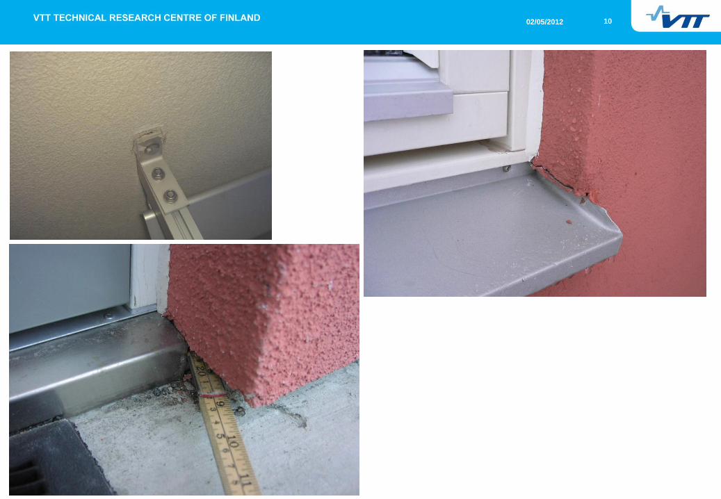
10 02/05/2012
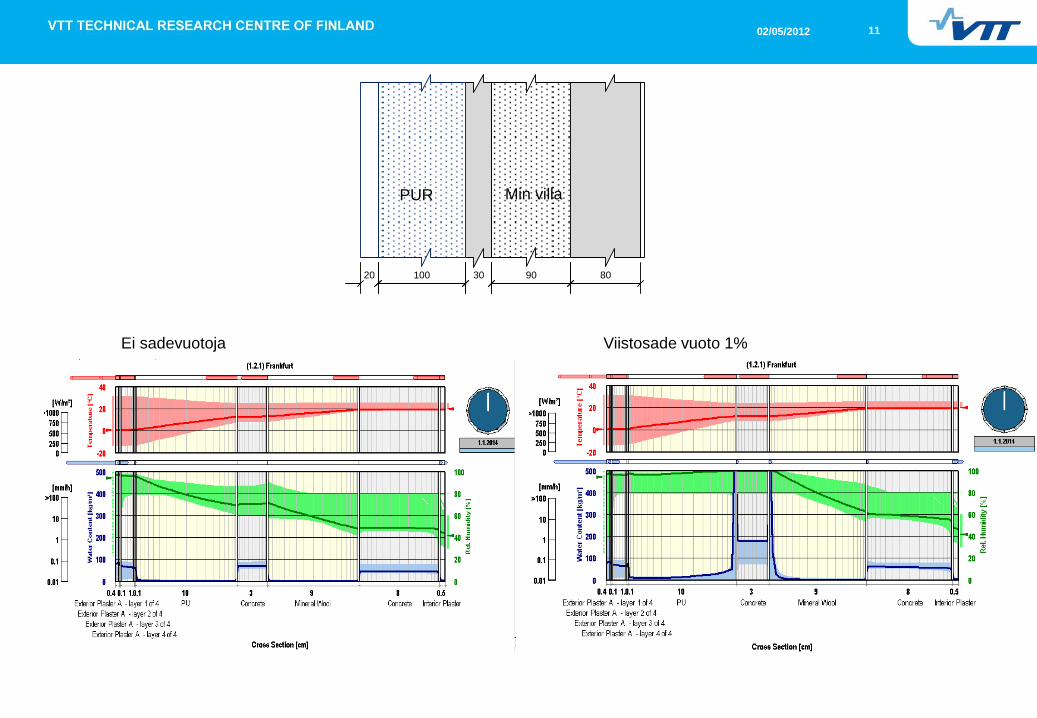
11 02/05/2012
30 90 8010020
Min villa PUR
Viistosade vuoto 1% Ei sadevuotoja

12 02/05/2012
30 90 801003020
Viistosade vuoto 1% Ei sadevuotoja

13 02/05/2012
Degredation models 1
Internal Frost Attack
Internal Frost attack was evaluated based on the theory of Göran Fagerlund (theory of Critical Degree of Saturation). The progress of frost attack depends on the factor KN (depending on the number of freeze-thaw cycles) and the excess of critical degree of saturation at each freeze-thaw cycle
RDM is degree of damage or relative dynamic modulus (0 <
RDM < 1)
N number of critical freezing events,
S active degree of saturation at the moment of freezing,
Scr critical degree of saturation,
KN coefficient of degradation.
A, B and C are constants
Vcap is volume of all capillary pores (and other water filled
pores smaller than capillary pores),
Vair;tot total volume of air pores,
Vair;cr critical volume of (water filled) air pores
)(10
crN
N SSKE
ERDM
NB
NAK
C
N
totaircap
craircap
crVV
VVS
;
;
14 02/05/2012
Degredation models 2
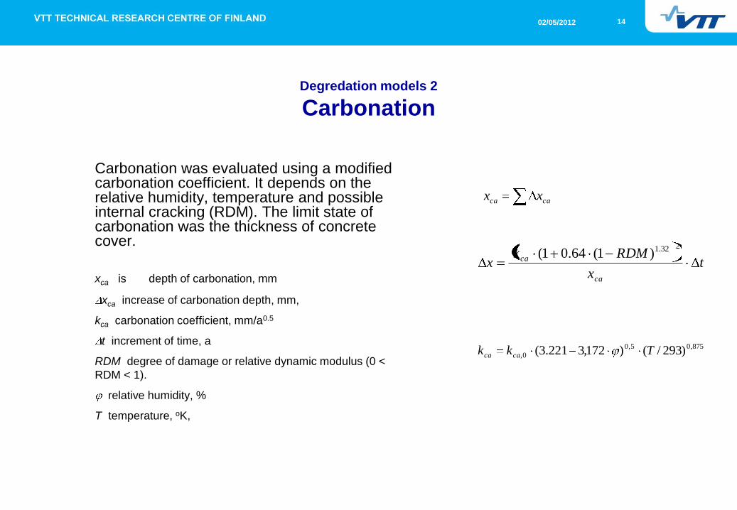
Carbonation
Carbonation was evaluated using a modified carbonation coefficient. It depends on the relative humidity, temperature and possible internal cracking (RDM). The limit state of carbonation was the thickness of concrete cover.
xca is depth of carbonation, mm
xca increase of carbonation depth, mm,
kca carbonation coefficient, mm/a0.5
t increment of time, a
RDM degree of damage or relative dynamic modulus (0 <
RDM < 1).
relative humidity, %
T temperature, oK,
caca xx
tx
RDMkx
ca
ca
232.1)1(64.01(
875,05,0
0, )293/()172,3221.3( Tkk caca
15 02/05/2012
Degredation models 3
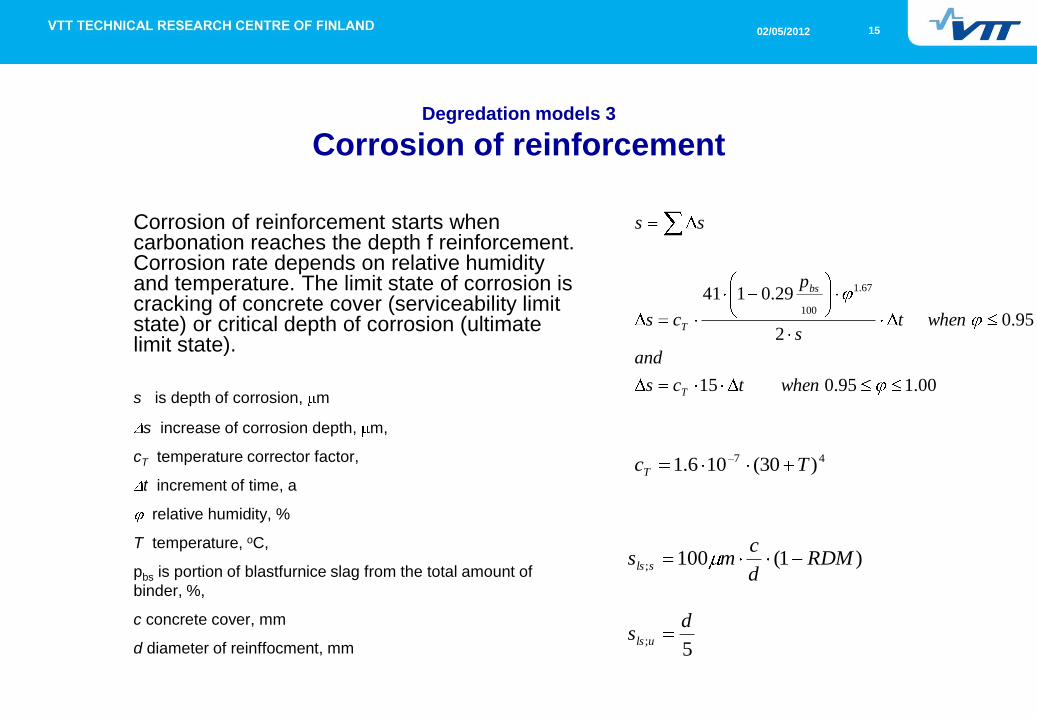
Corrosion of reinforcement
Corrosion of reinforcement starts when carbonation reaches the depth f reinforcement. Corrosion rate depends on relative humidity and temperature. The limit state of corrosion is cracking of concrete cover (serviceability limit state) or critical depth of corrosion (ultimate limit state).
s is depth of corrosion, m
s increase of corrosion depth, m,
cT temperature corrector factor,
t increment of time, a
relative humidity, %
T temperature, oC,
pbs is portion of blastfurnice slag from the total amount of
binder, %,
c concrete cover, mm
d diameter of reinffocment, mm
ss
00.195.015
95.02
29.0141 67.1
100
whentcs
and
whents
p
cs
T
bs
T
47 )30(106.1 TcT
)1(100; RDMd
cms sls
5;
ds uls

16 02/05/2012
Degradation models 4
Mould growth
Mould growth index M can be determined by using the temperature and relative humidity histories of the subjected material surfaces.
M is mould growth index
s increase of corrosion depth, m,
relative humidity, %
T temperature, oC, pbs is portion of blastfurnice slag from the total
amount of binder, %,
c concrete cover, mm
d diameter of reinffocment, mm
2
max100100 crit
crit
crit
crit
RH
RHRHC
RH
RHRHBAM
tkkt
M
MM
m
21
1
hoursRHTtm )02.66ln9.13ln68.0exp(247
0,)(3.2exp1max max2 MMk
Sensitivity class k1 k2
(Mmax)
RHmi
n
M<1 M>1 A B C %
Very sensititive (vs)
Sensitive (s)
Medium resistant (mr)
Resistant (r)
1
0.578
0.072
0.033
2
0.386
0.097
0.014
1
0.3
0
0
7
6
5
3
2
1
1.5
1
80
80
85
85

17 02/05/2012
Jyväskylä, Original structure, MW
Jyväskylä , MW
-40
-30
-20
-10
0
10
20
30
40
50
60
0 50 100 150 200 250 300 350
Time (days)
Te
mp
era
ture
(oC
)
Orig Front
Orig Back
Jyväskylä , MW
80
90
100
110
120
130
140
150
160
170
180
0 50 100 150 200 250 300 350
Time (days)
Wa
ter
co
nte
nt
(kg
/m3)
Orig Front
Orig Back
Wcritical
30 90 80
Jyväskylä , MW
0
0.1
0.2
0.3
0.4
0.5
0.6
0.7
0.8
0.9
1
0 20 40 60 80 100 120 140
Time (years)
Co
rro
sio
n (
rela
tive
to
lim
it s
tate
)
Orig Front
Orig Back
MW
Time of repair = 65 years

18 02/05/2012
30 90 8010020
Jyväskylä, Concept E1, MW
Jyväskylä , MW
0
0.1
0.2
0.3
0.4
0.5
0.6
0.7
0.8
0.9
1
0 20 40 60 80 100 120 140
Time (years)
Corr
osio
n (
rela
tive to li
mit
sta
te)
Orig Front
Orig Back
Before repair:
relative to serviceability
limit state
After repair:
Relative to ultimate limit state
Jyväskylä , MW
0
1
2
3
4
5
6
0 20 40 60 80 100 120 140
Time (years)
Mo
uld
Gro
wth
In
de
x
Orig Front
Orig Back
MW MW
Repair
Repair

19 02/05/2012
30 90 8010020
Jyväskylä, Concept E1, PUR
Jyväskylä , PUR
0
0.1
0.2
0.3
0.4
0.5
0.6
0.7
0.8
0.9
1
0 20 40 60 80 100 120 140
Time (years)
Corr
osio
n (
rela
tive to li
mit
sta
te)
Orig Front
Orig Back
Before repair:
relative to serviceability
limit state
After repair:
Relative to ultimate limit state
MW PUR
Jyväskylä , PUR
0
1
2
3
4
5
6
0 20 40 60 80 100 120 140
Time (years)
Mo
uld
Gro
wth
In
de
xOrig Front
Orig Back
Repair
Repair Temporary mould problem

20 02/05/2012
30 90 80 50
ESP
MW
or
PUR
Interior refurbishment, I
21 02/05/2012
Important considerations
Air tightness
Water vapour permeability decreases towards the outside surface
Driving rain leakages are harmful
Ventilated facade improves the drying potential of the wall

22 02/05/2012
Refurbishment Concept E1, E2 – additional insulation laid on the original
outer core of the sandwich and covered by a layer of rendering.
- External added insulation - existing wall becomes warmer and drier
- Avoid structural layers between 2 vapour tight insulations (PUR, EPS)
- Frost attack

23 02/05/2012
Refurbishment Concept I – additional insulation laid on the interior side
- Condensation risk if vapour tight layers are in the existing wall,
- Thermal bridges are created between floor and wall junctions

24 02/05/2012
External insulation (E) - New outer service with retrofit insulation – effect on Fire Safety
A = Small houses
B = Terraced houses
C = Multi storey
External structures/layers:
Thin non-combustible =
Metal, rendering, etc.
Combustible = Wood, PVC,
etc.
Non-combustible
insulation = Mineral
wool
Combustible
insulation = EPS/XPS,
PUR/PIR, cellulose
based, etc.
E1 = Insulation fixed
without air gap
E2 = Insulation fixed
with air gap and
wind protection
WALL TYPE
BUILD
ING
TYPE
Type of external
structure/layer Type of insulation
Score
E1 E2
W2_Sandwich
element; concrete
panel + concrete
panel
C Concrete or similar Non-combustible 0 0
Combustible 0 -1
Thin non-
combustible
Non-combustible 0 0
Combustible -1 -2
Combustible Non-combustible -1 -2
Combustible -2 -2
Assessments of the refurbishment External insulation’s effect on the fire safety of the external wall and facade

25 02/05/2012
Recommendations
Considering durability aspects of the wall, excessive moisture is harmful.
Excessive moisture levels may cause mould to develop in the wall. This
may be a risk considering also the indoor air quality.
Considering fire safety, to reach the intended fire safety level for multi-
storey buildings, it is recommended to use non-combustible (=A1 or A2-s1,
d0 reaction to fire class) or at least B-s1, d0 class external boards/layers.
Considering structural stability the assessment of the load bearing capacity
of the existing walls must include a verification to ensure that it can
withstand the mounting of fastening points.
Considering buildability, the aspects which need to be checked are the
needs of space, availability of materials, work force, quality of
workmanship. These will depend on the project at hand and on the local
conditions.


![EX SERIES...(Mexico only] or log onto our website at . . 8 ; ... • Usethe+(D2.2)or-(D2.1) keytosetthenumberofhours until the appliance should start up. Whenthesettimeiselapsed,theappliancewillstarttooperate](https://img.pdfslide.tips/doc/110x75/5f21f7cb3a0579250a2ec459/ex-series-mexico-only-or-log-onto-our-website-at-8-a-usethed22or-d21.jpg)