Embed Size (px)
Citation preview
94
KRUTOST PRITEGNUTIH PLATFORMI
I. Senjanović, N. Hadžić, M. Tomić, N. Vladimir Sveučilište u Zagrebu, Fakultet strojarstva i brodogradnje
SAŽETAK: Pritegnuta platforma spada u tip podatljivih pomorskih konstrukcija koje se koriste za istraživanje nafte u dubokom moru. Usidrena je vrlo fleksibilnim pritegama koje omogućuju relativno velike amplitude zanošenja. Trup platforme smatra se krutim tijelom sa šest stupnjeva slobode gibanja. U dinamičkom odzivu pritegnute platforme važnu ulogu ima ukupna povratna krutost. Iako u literaturi postoji nekoliko formulacija povratne krutosti, nijedna od njih nije potpuno adekvatna, pri čemu je osnovni problem realistične definicije centra rotacije. U ovom radu prikazana je konzistentna formulacija matrice krutosti, izvedena iz općeg rješenja za hidroelastičnu analizu brodskih konstrukcija, kao poseban slučaj. Ukupna krutost pritegnute platforme u dinamičkoj analizi sastoji se od hidrostatičke krutosti trupa (s komponentama gravitacijske sile i sile vanjskog tlaka), te konvencionalne i geometrijske krutosti pritega. Analizirane su i obrazložene razlike između nove i od prije poznatih formulacija krutosti. Ključne riječi: pritegnuta platforma, povratna krutost, geometrijska krutost
STIFFNESS OF TENSION LEG PLATFORMS
I. Senjanović, N. Hadžić, M. Tomić, N. Vladimir
University of Zagreb, Faculty of Mechanical Engineering and Naval Architecture, Ivana Lučića 5, 10000 Zagreb, CROATIA
ABSTRACT: The tension leg platform (TLP) is a type of compliant offshore structures generally used for deep water oil exploration. It is moored by very flexible tendons so that surge amplitude can achieve large value. The platform hull is considered as a rigid body with six d.o.f. The total restoring stiffness plays very important role in the TLP dynamic behavior. Although there are several stiffness formulations available in the present literature, none of them is completely adequate. The issue is to define realistic centre of rotations. The consistent formulation of stiffness matrix is presented in this paper. It is derived from the general solution established for hydroelastic analysis of ship structures, as a specific case. Actually, the total TLP stiffness in dynamic analysis consists of hydrostatic hull stiffness (pressure and
95
gravity), and conventional and geometric tendon stiffness. The new stiffness is compared to the known ones, and discrepancies are analyzed and discussed. Key words: tension leg platform; restoring stiffness; geometric stiffness 1. INTRODUCTION A tension leg platform (TLP) is a semi-submersible platform, moored by vertical pretensioned tendons or tethers [1]. The platform constitutive parts are pontoon, columns and deck with drilling equipment [2]. Heave, roll and pitch have high natural frequencies due to high tendon axial stiffness. Surge, sway and yaw are compliant modes due to quite low tendon geometric stiffness. Vertical motions are excited by the first order wave forces, while horizontal motions appear due to the second order wave forces with very low frequency [3]. Stiffness plays very important role in dynamic analysis of TLPs [4]. Platform can be considered as a rigid body with tendons as massless quasi-static springs. The hydrodynamic coefficients can be determined by Morison’s equation or the radiation-diffraction theory, depending on the ratio of diameters of platform cylindrical segments and the wave length. Since even linear stiffness is not formulated in the relevant literature in a consistent way, the new formulation is presented in Section 2, and its comparison with the known formulations is elaborated in Section 3. Additional comparison is done via numerical example, Section 4. 2. LINEAR STIFFNESS 2.1. Definition of total stiffness Let us consider a double symmetric TLP with N tendons, Figure 1. The origin of the coordinate system is located in the middle of the waterplane, and the motion components are shown in Figure 2. The platform is treated as a rigid body due to very high stiffness compared to that of tendons. The total stiffness consists of three parts: [ ] [ ] [ ] [ ]C G
PK K C K= + + (1)
where [ ]CK is the conventional tendon stiffness, [ ]C is the platform restoring stiffness with influence of tendons included, and [ ]GK is the tendon geometric stiffness. 2.2. Conventional stiffness The tendons are steel pipes with negligibly small bending stiffness. Heave changes the tension of tendons so that the stiffness is the relation between vertical force and displacement:
96
331
,N
Cn
n
EAk A AL =
= =∑ . (2)
The tension of tendons is also changed by roll and the corresponding stiffness is found from the moment as function of the roll angle. Since
1, , and
Nn n n nn
x z n z z z n xn
EAM F y F yL
δ δ ϕ=
= = =∑ , (3)
one gets: 2
441
,N
C xX n n
n
EIk I A yL =
= =∑ . (4)
In the similar way, the pitch stiffness is: 2
551
,N
yCy n n
n
EIk I A x
L =
= =∑ , (5)
where A, Ix, and Iy are the total cross-section area and moments of inertia about x and y axis of all tendons, respectively. Hence, set of tendons is considered as a beam with distinct fibers. 2.3. Restoring stiffness Hydroelastic analysis of a deformable floating body is usually performed by the modal superposition method. The ordinary restoring stiffness consists of variation of hydrostatic pressure, variation of normal vector and natural mode and gravity part respectively, [5]:
o p nh mij ij ij ijC C C C= + + , (6)
3 dp i jij k k
S
C g h h n Sρ= ∫∫ , (7)
, dnh i jij k l l k
S
C g Zh h n Sρ= ∫∫ , (8)
3, dm i jij S k k
V
C g h h Sρ= ∫∫∫ , (9)
where, according to the index notation, ,ik lh is the l-th derivative of the k-th
component of the natural mode hi, S is the wetted surface, nk are components of its normal vector, V is the structure volume, while ρ and ρs are the water and structure density, respectively.
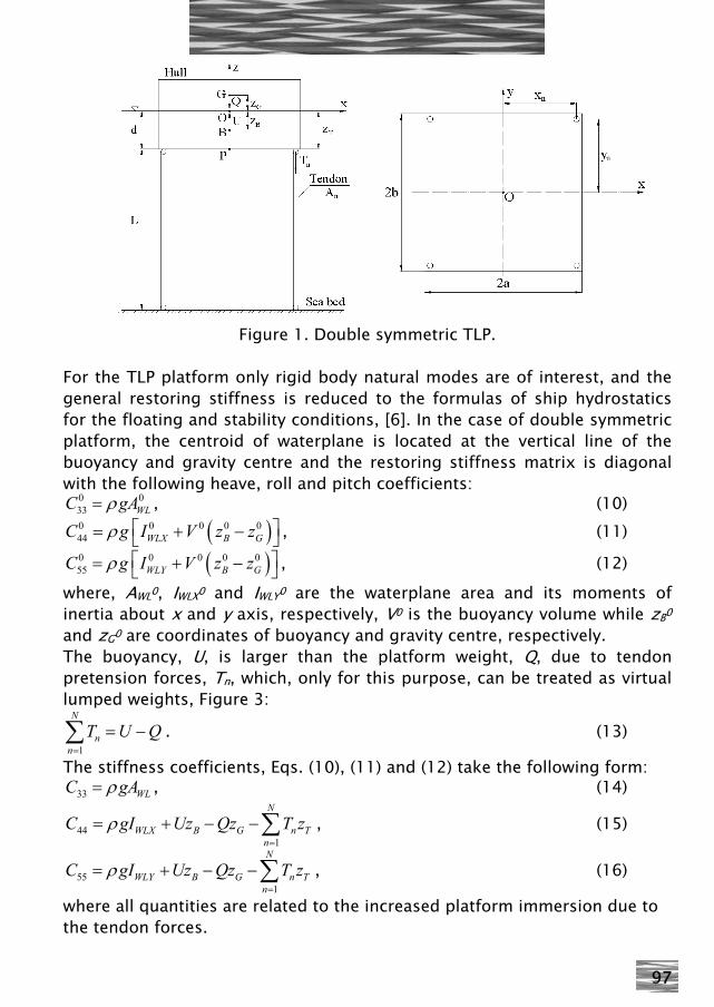
97
Figure 1. Double symmetric TLP. For the TLP platform only rigid body natural modes are of interest, and the general restoring stiffness is reduced to the formulas of ship hydrostatics for the floating and stability conditions, [6]. In the case of double symmetric platform, the centroid of waterplane is located at the vertical line of the buoyancy and gravity centre and the restoring stiffness matrix is diagonal with the following heave, roll and pitch coefficients:
0 033 WLC gAρ= , (10)
( )0 0 0 0 044 WLX B GC g I V z zρ ⎡ ⎤= + −⎣ ⎦ , (11)
( )0 0 0 0 055 WLY B GC g I V z zρ ⎡ ⎤= + −⎣ ⎦ , (12)
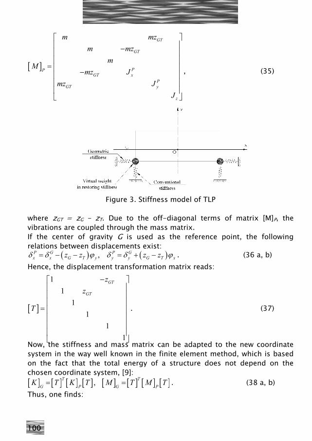
where, AWL0, IWLX0 and IWLY0 are the waterplane area and its moments of inertia about x and y axis, respectively, V0 is the buoyancy volume while zB0 and zG0 are coordinates of buoyancy and gravity centre, respectively. The buoyancy, U, is larger than the platform weight, Q, due to tendon pretension forces, Tn, which, only for this purpose, can be treated as virtual lumped weights, Figure 3:
1
N
nn
T U Q=
= −∑ . (13)
The stiffness coefficients, Eqs. (10), (11) and (12) take the following form: 33 WLC gAρ= , (14)
441
N
WLX B G n Tn
C gI Uz Qz T zρ=
= + − −∑ , (15)
551
N
WLY B G n Tn
C gI Uz Qz T zρ=
= + − −∑ , (16)
where all quantities are related to the increased platform immersion due to the tendon forces.
98
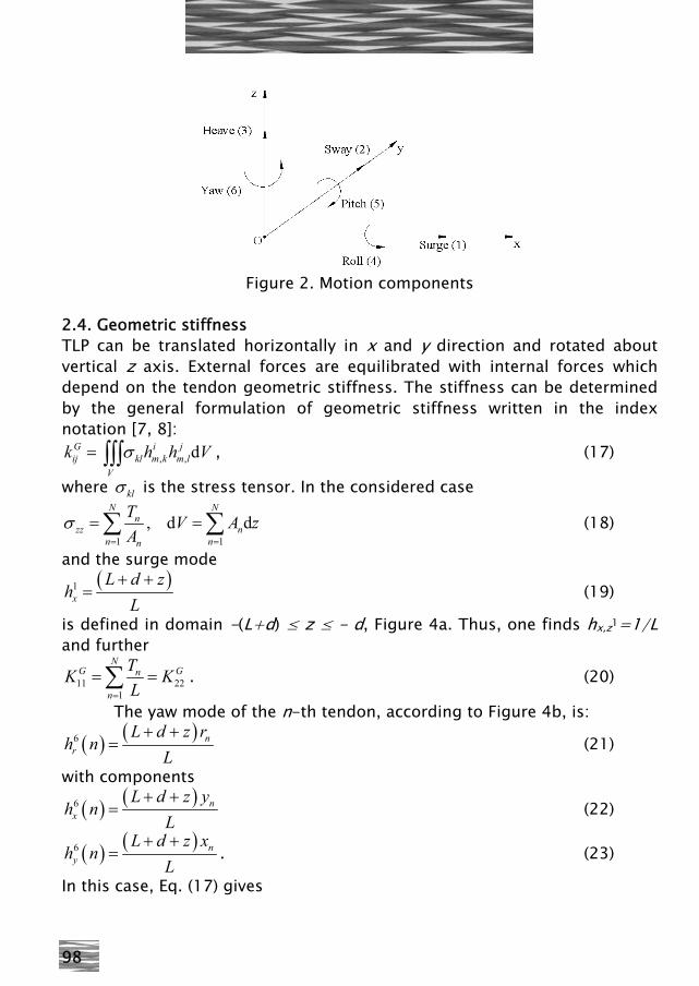
Figure 2. Motion components
2.4. Geometric stiffness TLP can be translated horizontally in x and y direction and rotated about vertical z axis. External forces are equilibrated with internal forces which depend on the tendon geometric stiffness. The stiffness can be determined by the general formulation of geometric stiffness written in the index notation [7, 8]:
, , dG i jij kl m k m l
V
k h h Vσ= ∫∫∫ , (17)
where klσ is the stress tensor. In the considered case
1 1
, d dN N
nzz n
n nn
T V A zA
σ= =
= =∑ ∑ (18)
and the surge mode ( )1
x
L d zh
L+ +
= (19)
is defined in domain -(L+d) ≤ z ≤ - d, Figure 4a. Thus, one finds hx,z1=1/L and further
11 221
NG Gn
n
TK KL=
= =∑ . (20)
The yaw mode of the n-th tendon, according to Figure 4b, is:
( ) ( )6 nr
L d z rh n
L+ +
= (21)
with components
( ) ( )6 nx
L d z yh n
L+ +
= (22)
( ) ( )6 ny
L d z xh n
L+ +
= . (23)
In this case, Eq. (17) gives
99
( )2 2
661
Nn n nG
n
T x yK
L=
+=∑ . (24)
2.5. Total stiffness and mass matrix By summing up the terms of conventional, restoring and geometric stiffness, determined in previous sections, elements of the total stiffness matrix [K]P, Eq. (1), are obtained:
11 22 331
,N
nWL
n
T EAK K K gAL L
ρ=
= = = +∑ , (25a, b)
441
Nx
WLX B G n Tn
EIK gI Uz Qz T zL
ρ=
= + − − +∑ , (26)
551
Ny
WLY B G n Tn
EIK gI Uz Qz T z
Lρ
=
= + − − +∑ , (27)
( )2 266
1
Nn
n nn
TK x yL=
= +∑ . (28)
The total stiffness matrix is a diagonal one because the middle point of hull bottom is used as pole P, Figure 4, for the platform rotations. As a result, there is no coupling between degrees of freedom through the stiffness. On the other side, the mass matrix has some off-diagonal elements since the following inertia forces (designated with i) depend on both displacements and rotations:
( )ix x G T yF m m z zδ ϕ= + − (29)
( )iy y G T xF m m z zδ ϕ= − − (30)
( )i Px G T y x xM m z z Jδ ϕ= − − + (31)
( )i Py G T x y yM m z z Jδ ϕ= − + (32)
where ( )2P G
x x G TJ J m z z= + − (33)
( )2P Gy y G TJ J m z z= + − (34)
are the mass moments of inertia. The mass matrix with respect to the pole P, reads:
100
[ ]
⎡ ⎤⎢ ⎥−⎢ ⎥⎢ ⎥
= ⎢ ⎥−⎢ ⎥⎢ ⎥⎢ ⎥⎣ ⎦
GT
GT
PPGT x
PGT y
z
m mzm mz
mM
mz Jmz J
J
, (35)
Figure 3. Stiffness model of TLP
where zGT = zG - zT. Due to the off-diagonal terms of matrix [M]P, the vibrations are coupled through the mass matrix. If the center of gravity G is used as the reference point, the following relations between displacements exist:
( ) ( ),P G P Gx x G T y y y G T xz z z zδ δ ϕ δ δ ϕ= − − = + − . (36 a, b)
Hence, the displacement transformation matrix reads:
[ ]
11
11
11
GT
GT
zz
T
−⎡ ⎤⎢ ⎥⎢ ⎥⎢ ⎥
= ⎢ ⎥⎢ ⎥⎢ ⎥⎢ ⎥⎣ ⎦
. (37)
Now, the stiffness and mass matrix can be adapted to the new coordinate system in the way well known in the finite element method, which is based on the fact that the total energy of a structure does not depend on the chosen coordinate system, [9]: [ ] [ ] [ ] [ ] [ ] [ ] [ ] [ ],T T
G P G PK T K T M T M T= = . (38 a, b)
Thus, one finds:
101
[ ]
11 11
22 22
33,2
22 44 222
5511 11
66
K z KGTK z KGT
KK G z K K z KGT GT
z K K z KGT GTK
−
=+
− +
⎡ ⎤⎢ ⎥⎢ ⎥⎢ ⎥⎢ ⎥⎢ ⎥⎢ ⎥⎢ ⎥⎣ ⎦
(39)
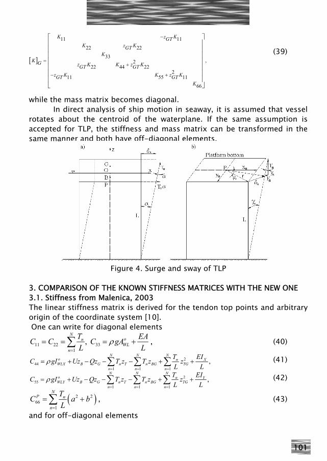
while the mass matrix becomes diagonal. In direct analysis of ship motion in seaway, it is assumed that vessel rotates about the centroid of the waterplane. If the same assumption is accepted for TLP, the stiffness and mass matrix can be transformed in the same manner and both have off-diagonal elements.
Figure 4. Surge and sway of TLP
3. COMPARISON OF THE KNOWN STIFFNESS MATRICES WITH THE NEW ONE 3.1. Stiffness from Malenica, 2003 The linear stiffness matrix is derived for the tendon top points and arbitrary origin of the coordinate system [10]. One can write for diagonal elements
11 22 331
, N
onWL
n
T EAC C C gAL L
ρ=
= = = +∑ , (40)
244
1 1 1
,N N N
o n XWLX B G n T n BG TG
n n n
T EIC gI Uz Qz T z T z zL L
ρ= = =
= + − − − + +∑ ∑ ∑ (41)
255
1 1 1
,N N N
o n YWLY B G n T n BG TG
n n n
T EIC gI Uz Qz T z T z zL L
ρ= = =
= + − − − + +∑ ∑ ∑ (42)
( )2 266
1
NP n
n
TC a bL=
= +∑ , (43)
and for off-diagonal elements
102
15 24 42 511 1 1 1
, , , N N N N
n n n nTG TG TG TG
n n n n
T T T TC z C z C z C zL L L L= = = =
= = − = − =∑ ∑ ∑ ∑ .(44)
By comparing Eqs. (40) – (44) with Eq. (39) some differences can be noticed. The 5th term in Eqs. (41) and (42) is additional. The off-diagonal elements (44) are identical as those in (39) since zTG=- zGT. 3.2. Stiffness from Jain, 1997 Nonlinear stiffness matrix presented in [11] is ordinary used for dynamic analysis of TLP. It is specified with respect to the centre of gravity. Its linear part reads:
[ ]
11
22
33
42 44
51 55
66
L
L
LL
L LG
L L
L
KK
KK
K KK K
K
⎡ ⎤⎢ ⎥⎢ ⎥⎢ ⎥
= ⎢ ⎥⎢ ⎥⎢ ⎥⎢ ⎥⎢ ⎥⎣ ⎦
, (45)
where elements K11L, K22L, K33L and K66L are equal to Eqs. (25a,b) and (28), while the remaining elements are
441
NL X
WL G G n Tn
EIK gA Uz Qz T zL
ρ=
= + − − +∑ , (46)
551
NL Y
WL G G n Tn
EIK gA Uz Qz T zL
ρ=
= + − − +∑ . (47)
By comparing Eqs. (46) and (47) with Eq. (39) it is noticed that the coordinate of the gravity center zG is accompanied to the buoyancy U instead of its own zB. Since Eq. (45) is derived with respect to the gravity center it should have additional terms K15L and K24L like Eq. (39). 3.3. Stiffness from Low, 2009 Recently, a new formulation of nonlinear stiffness matrix, based on energy approach, is presented in [12]. Its linear part reads
103
[ ]
( )
1
1
02
02
0
2 21
L
kk
kK k b
k a
k a b
⎡ ⎤⎢ ⎥⎢ ⎥⎢ ⎥⎢ ⎥=⎢ ⎥⎢ ⎥⎢ ⎥
+⎢ ⎥⎣ ⎦
, (48)
where
0 11
, N
n
n
TEAk kL L=
= =∑ . (49)
It is obvious that only the tendon contribution is taken into account, while the restoring stiffness is ignored. 4. NUMERICAL EXAMPLE Outlined theory is illustrated by analyzing a TLP spar floater without the installed wind turbine [13]. Hydrodynamic part of fluid loading (added mass, radiation damping, Froude-Krylov and diffraction loads) and the equations of motion (solved for the centre of gravity of the floater) are calculated using the Bureau Veritas HYDROSTAR software [14].
Spar diameter 4 m Water depth 200 mSpar draft 10 m Mass 49002.3 kgThickness 25.3 mm Buoyant mass 149887.8 kgSpoke length 5 m COG -6.698 mSpoke width 1 m COB -5.687 mLine diameter 50 mm Jxx 1140080.9 kg m^2Number of lines 1 per spoke Jyy 1140080.9 kg m^2Line length 190 m Jzz 451478 kg m^2
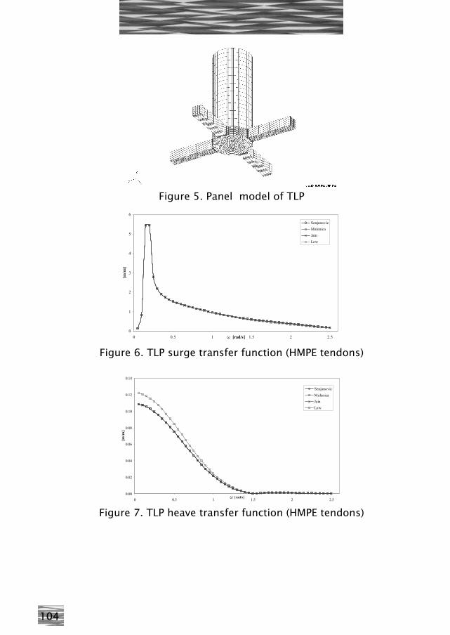
Table 1. Particulars of a TLP spar floater The mean wetted surface of a TLP spar floater is discretized into 2272 panels. Tendons were not included in the hydrodynamic model, and their influence on the platform is taken into account via stiffness matrix. Two distinctive cases were analyzed, one using high modulus polyester tendons (HMPE, E=2.5 1010 N/m2) and the other using the usual steel tendons (STEEL, E=2.06 1011 N/m2). HMPE tendons are used in order to lower the stiffness and thus allow larger oscillation amplitudes. Frequency domain responses (1st order motion transfer functions) were calculated for a range of frequencies in 1m head waves (180 deg wave heading). Please note that the ratio between the response amplitude and wave amplitude is called transfer function in this paper.
104
Figure 5. Panel model of TLP
0
1
2
3
4
5
6
0 0.5 1 1.5 2 2.5w [rad/s]
[m/m
]
SenjanovicMalenicaJainLow
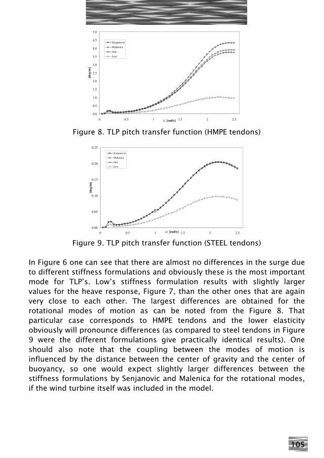
Figure 6. TLP surge transfer function (HMPE tendons)
0.00
0.02
0.04
0.06
0.08
0.10
0.12
0.14
0 0.5 1 1.5 2 2.5w [rad/s]
[m/m
]
SenjanovicMalenicaJainLow
Figure 7. TLP heave transfer function (HMPE tendons)
105
0.0
0.5
1.0
1.5
2.0
2.5
3.0
3.5
4.0
4.5
5.0
0 0.5 1 1.5 2 2.5w [rad/s]
[deg
/m]
SenjanovicMalenicaJainLow
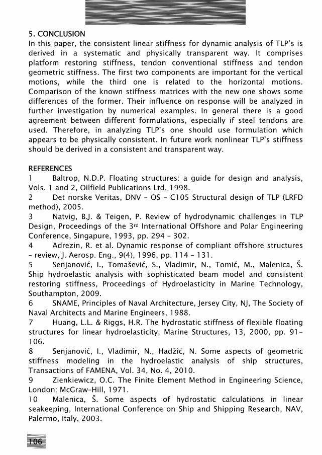
Figure 8. TLP pitch transfer function (HMPE tendons)
0.00
0.05
0.10
0.15
0.20
0.25
0 0.5 1 1.5 2 2.5w [rad/s]
[deg
/m]
SenjanovicMalenicaJainLow
Figure 9. TLP pitch transfer function (STEEL tendons)
In Figure 6 one can see that there are almost no differences in the surge due to different stiffness formulations and obviously these is the most important mode for TLP’s. Low’s stiffness formulation results with slightly larger values for the heave response, Figure 7, than the other ones that are again very close to each other. The largest differences are obtained for the rotational modes of motion as can be noted from the Figure 8. That particular case corresponds to HMPE tendons and the lower elasticity obviously will pronounce differences (as compared to steel tendons in Figure 9 were the different formulations give practically identical results). One should also note that the coupling between the modes of motion is influenced by the distance between the center of gravity and the center of buoyancy, so one would expect slightly larger differences between the stiffness formulations by Senjanovic and Malenica for the rotational modes, if the wind turbine itself was included in the model.
106
5. CONCLUSION In this paper, the consistent linear stiffness for dynamic analysis of TLP’s is derived in a systematic and physically transparent way. It comprises platform restoring stiffness, tendon conventional stiffness and tendon geometric stiffness. The first two components are important for the vertical motions, while the third one is related to the horizontal motions. Comparison of the known stiffness matrices with the new one shows some differences of the former. Their influence on response will be analyzed in further investigation by numerical examples. In general there is a good agreement between different formulations, especially if steel tendons are used. Therefore, in analyzing TLP’s one should use formulation which appears to be physically consistent. In future work nonlinear TLP’s stiffness should be derived in a consistent and transparent way. REFERENCES 1 Baltrop, N.D.P. Floating structures: a guide for design and analysis, Vols. 1 and 2, Oilfield Publications Ltd, 1998. 2 Det norske Veritas, DNV – OS – C105 Structural design of TLP (LRFD method), 2005. 3 Natvig, B.J. & Teigen, P. Review of hydrodynamic challenges in TLP Design, Proceedings of the 3rd International Offshore and Polar Engineering Conference, Singapure, 1993, pp. 294 – 302. 4 Adrezin, R. et al. Dynamic response of compliant offshore structures – review, J. Aerosp. Eng., 9(4), 1996, pp. 114 – 131. 5 Senjanović, I., Tomašević, S., Vladimir, N., Tomić, M., Malenica, Š. Ship hydroelastic analysis with sophisticated beam model and consistent restoring stiffness, Proceedings of Hydroelasticity in Marine Technology, Southampton, 2009. 6 SNAME, Principles of Naval Architecture, Jersey City, NJ, The Society of Naval Architects and Marine Engineers, 1988. 7 Huang, L.L. & Riggs, H.R. The hydrostatic stiffness of flexible floating structures for linear hydroelasticity, Marine Structures, 13, 2000, pp. 91-106. 8 Senjanović, I., Vladimir, N., Hadžić, N. Some aspects of geometric stiffness modeling in the hydroelastic analysis of ship structures, Transactions of FAMENA, Vol. 34, No. 4, 2010. 9 Zienkiewicz, O.C. The Finite Element Method in Engineering Science, London: McGraw–Hill, 1971. 10 Malenica, Š. Some aspects of hydrostatic calculations in linear seakeeping, International Conference on Ship and Shipping Research, NAV, Palermo, Italy, 2003.
107
11 Jain, A.K. Nonlinear coupled response of offshore tension leg platform to regular wave forces, Ocean Engineering, 24(7), 1997, pp. 577-593. 12 Low, M.Y. Frequency domain analysis of a tension leg platform with statistical linearization of the tendon restoring forces, Marine Structures, 22, 2009, pp. 480-503. 13 Withee, J.E. Fully coupled dynamic analysis of a floating wind turbine system, PhD thesis, MIT, USA, 2004. 14 Chen, X. Hydrodynamics in offshore and naval applications – part I., Keynote Lecture, 6th International Conference on Hydrodynamics, Perth, Australia, 2004.
NON-LINEAR FEM STUDY OF A SHIP GROUNDING
M. Srdelić, Fakultet strojarstva i brodogradnje u Zagrebu S. Rudan, Fakultet strojarstva i brodogradnje u Zagrebu
ABSTRACT: Ship grounding is a complex event determined by ship speed and heading, type of the obstacle in a way, hydrodynamic effects and other factors. Non-linear finite element method (NFEM) analysis is a sophisticated tool for modeling and analysis of such events. Obtaining realistic results, however, requires careful modeling. This paper presents a concept for ship grounding numerical model. The 3D model of a ship was generated. Hull is modeled using beam elements, while fore peak is modeled in detail. Nonlinear buoyancy is taken into account. Several types of fixed ground were considered. Ship particulars and mass, as well as basic kinetic parameters were chosen to resemble Marko Polo, grounded on Sit island in October 2009. Results are presented and comment is made on possible application and improvement of the method. Keywords: ship grounding, hard grounding, non-linear finite element method, 3D FEM model 1. INTRODUCTION Ship grounding is a marine accident that occurs rarely, but often with serious consequences. Not only that ship gets damaged in certain extent, but people's lives and cargo may be endangered. Also, an imminent risk for environment pollution is present in all but lightest groundings. Although numerous measures are taken to prevent grounding (as well as collision) of the ships, they continue to happen due to various reasons. Because of that each maritime country takes notes and evidence of