Embed Size (px)
Citation preview
8/14/2019 L-02(SM)(IA&C) ((EE)NPTEL)
http://slidepdf.com/reader/full/l-02smiac-eenptel 1/21
Module1
IntroductionVersion 2 EE IIT, Kharagpur 1

8/14/2019 L-02(SM)(IA&C) ((EE)NPTEL)
http://slidepdf.com/reader/full/l-02smiac-eenptel 2/21

8/14/2019 L-02(SM)(IA&C) ((EE)NPTEL)
http://slidepdf.com/reader/full/l-02smiac-eenptel 3/21
Lesson Objectives
• To describe the various elements of an Industrial Automation Systems and how they areorganized hierarchically in levels.
• To explain how these levels relate to each other in terms of their functions.
• To describe the nature of technologies involved in realizing these functional levels
• To describe the nature of information processing in these levels and the information flowamong them
The Functional Elements of Industrial Automation
An Industrial Automation System consists of numerous elements that perform a variety of
functions related to Instrumentation, Control, Supervision and Operations Management related tothe industrial process. These elements may also communicate with one another to exchange
information necessary for overall coordination and optimized operation of the
plant/factory/process. Below, we classify the major functional elements typically found in IAsystems and also describe the nature of technologies that are employed to realize the functions.
Sensing and Actuation Elements
These elements interface directly and physically to the process equipment and machines. The
sensing elements translate the physical process signals such as temperature, pressure ordisplacement to convenient electrical or pneumatic forms of information, so that these signals
can be used for analysis, decisions and finally, computation of control inputs. These computed
control inputs, which again are in convenient electrical or pneumatic forms of information, needto be converted to physical process inputs such as, heat, force or flow-rate, before they can be
applied to effect the desired changes in the process outputs. Such physical control inputs areprovided by the actuation elements.
Industrial Sensors and Instrument Systems Scientific and engineering sensors and instrument systems of a spectacular variety of size,
weight, cost, complexity and technology are used in the modern industry. However, a close look
would reveal that all of them are composed of a set of typical functional elements connected in aspecified way to provide signal in a form necessary. The various tasks involved in the
automation systems. Fig 2.1 below shows the configuration of a typical sensor system.
MediumSensing
elementSignal
Conditioning
element
Target Signal
Handling
element
Signal
Processing
element
Fig. 2.1 Functional configuration of a typical sensor system
In Fig. 2.1 a sensor system is shown decomposed into three of its major functional components,
along with the medium in which the measurement takes place. These are described below.
Version 2 EE IIT, Kharagpur 3
8/14/2019 L-02(SM)(IA&C) ((EE)NPTEL)
http://slidepdf.com/reader/full/l-02smiac-eenptel 4/21
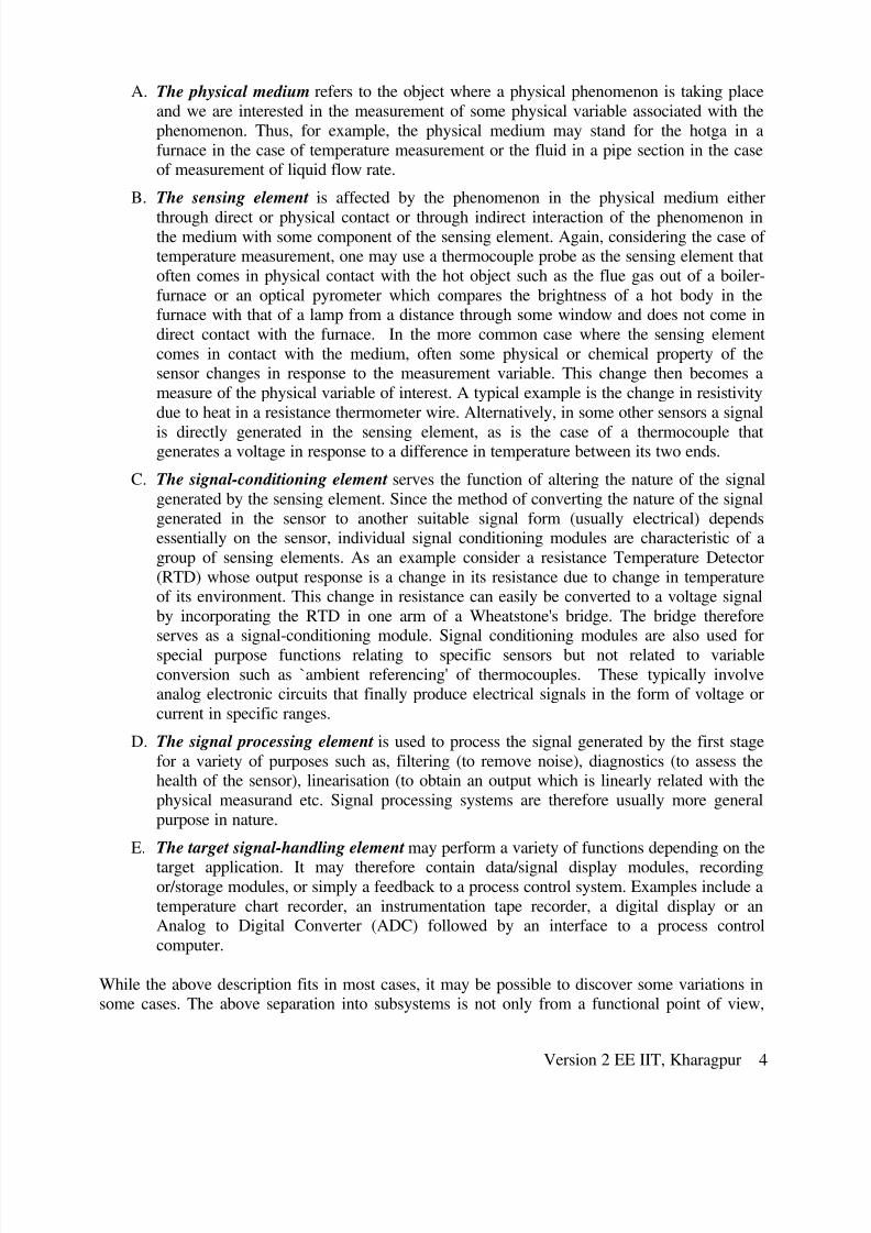
A. The physical medium refers to the object where a physical phenomenon is taking place
and we are interested in the measurement of some physical variable associated with the
phenomenon. Thus, for example, the physical medium may stand for the hotga in a
furnace in the case of temperature measurement or the fluid in a pipe section in the caseof measurement of liquid flow rate.
B. The sensing element is affected by the phenomenon in the physical medium either
through direct or physical contact or through indirect interaction of the phenomenon inthe medium with some component of the sensing element. Again, considering the case of temperature measurement, one may use a thermocouple probe as the sensing element that
often comes in physical contact with the hot object such as the flue gas out of a boiler-
furnace or an optical pyrometer which compares the brightness of a hot body in thefurnace with that of a lamp from a distance through some window and does not come in
direct contact with the furnace. In the more common case where the sensing element
comes in contact with the medium, often some physical or chemical property of thesensor changes in response to the measurement variable. This change then becomes a
measure of the physical variable of interest. A typical example is the change in resistivity
due to heat in a resistance thermometer wire. Alternatively, in some other sensors a signal
is directly generated in the sensing element, as is the case of a thermocouple thatgenerates a voltage in response to a difference in temperature between its two ends.
C. The signal-conditioning element serves the function of altering the nature of the signal
generated by the sensing element. Since the method of converting the nature of the signal
generated in the sensor to another suitable signal form (usually electrical) dependsessentially on the sensor, individual signal conditioning modules are characteristic of a
group of sensing elements. As an example consider a resistance Temperature Detector
(RTD) whose output response is a change in its resistance due to change in temperatureof its environment. This change in resistance can easily be converted to a voltage signal
by incorporating the RTD in one arm of a Wheatstone's bridge. The bridge thereforeserves as a signal-conditioning module. Signal conditioning modules are also used for
special purpose functions relating to specific sensors but not related to variable
conversion such as `ambient referencing' of thermocouples. These typically involveanalog electronic circuits that finally produce electrical signals in the form of voltage or
current in specific ranges.
D. The signal processing element is used to process the signal generated by the first stage
for a variety of purposes such as, filtering (to remove noise), diagnostics (to assess thehealth of the sensor), linearisation (to obtain an output which is linearly related with the
physical measurand etc. Signal processing systems are therefore usually more general
purpose in nature.
E. The target signal-handling element may perform a variety of functions depending on the
target application. It may therefore contain data/signal display modules, recordingor/storage modules, or simply a feedback to a process control system. Examples include a
temperature chart recorder, an instrumentation tape recorder, a digital display or anAnalog to Digital Converter (ADC) followed by an interface to a process control
computer.
While the above description fits in most cases, it may be possible to discover some variations insome cases. The above separation into subsystems is not only from a functional point of view,
Version 2 EE IIT, Kharagpur 4

8/14/2019 L-02(SM)(IA&C) ((EE)NPTEL)
http://slidepdf.com/reader/full/l-02smiac-eenptel 5/21
more often than not, these subsystems are clearly distinguishable physically in a measurement
system.
Modern sensors often have the additional capability of digital communication using serial,parallel or network communication protocols. Such sensors are called “smart” and contain
embedded digital electronic processing systems.
Point to Ponder: 1
A. Draw the functional block diagram of a typical sensor system
B. Consider a strain-gage weigh bridge. Explore and identify the subsystems of the bridge
and categorise these subsystems into the above mentioned classes of elements mentioned
above.
Industrial Actuator Systems
Actuation systems convert the input signals computed by the control systems into forms that canbe applied to the actual process and would produce the desired variations in the process physical
variables. In the same way as in sensors but in a reverse sense, these systems convert the
controller output, which is essentially information without the power, and in the form of electrical voltages (or at times pneumatic pressure) in two ways. Firstly it converts the form of
the variable into the appropriate physical variable, such as torque, heat or flow. Secondly it
amplifies the energy level of the signal manifold to be able to causes changes in the processvariables. Thus, while both sensors and actuators cause variable conversions, actuators are high
power devices while sensors are not. It turns out that in most cases, actuators are devices that
first produce motion from electrical signal, which is then further converted to other forms. Basedon the above requirement of energy and variable conversion most actuation systems are are
structured as shown in Fig. 2.2.
Signal
Processing
element
Power
Amplifying
Element
Energy
Conversion
Element
Variable
Conversion
Element
Process
Fig. 2.2 Functional configuration of a typical actuator system
In Fig.2.2 an actuator system is shown decomposed into its major functional components, The
salient points about the structure are described below.
A. The electronic signal-processing element accepts the command from the control system
in electrical form. The command is processed in various ways. For example it may be
filtered to avoid applying input signals of certain frequencies that may cause resonance.
Many actuators are themselves closed feedback controlled units for precision of theactuation operation. Therefore the electronic signal-processing unit often contains the
control system for the actuator itself.
Version 2 EE IIT, Kharagpur 5
8/14/2019 L-02(SM)(IA&C) ((EE)NPTEL)
http://slidepdf.com/reader/full/l-02smiac-eenptel 6/21
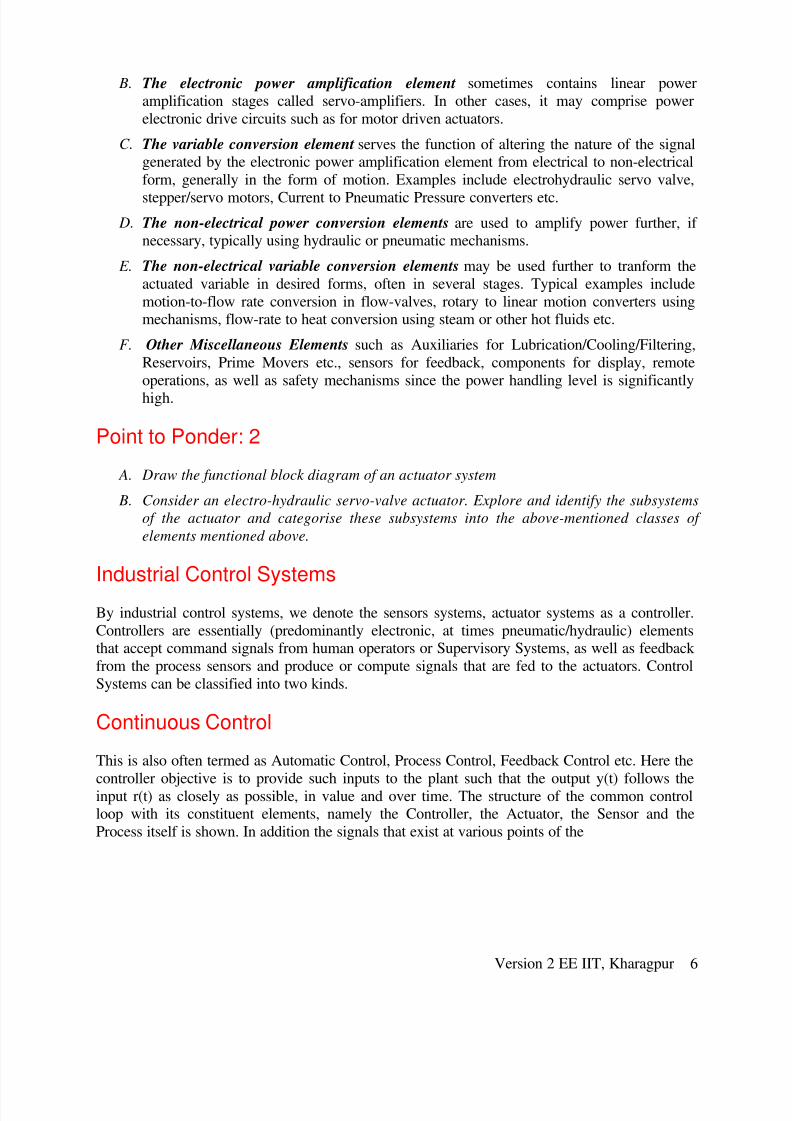
B. The electronic power amplification element sometimes contains linear power
amplification stages called servo-amplifiers. In other cases, it may comprise power
electronic drive circuits such as for motor driven actuators.
C. The variable conversion element serves the function of altering the nature of the signalgenerated by the electronic power amplification element from electrical to non-electrical
form, generally in the form of motion. Examples include electrohydraulic servo valve,
stepper/servo motors, Current to Pneumatic Pressure converters etc.
D. The non-electrical power conversion elements are used to amplify power further, if necessary, typically using hydraulic or pneumatic mechanisms.
E. The non-electrical variable conversion elements may be used further to tranform the
actuated variable in desired forms, often in several stages. Typical examples include
motion-to-flow rate conversion in flow-valves, rotary to linear motion converters usingmechanisms, flow-rate to heat conversion using steam or other hot fluids etc.
F. Other Miscellaneous Elements such as Auxiliaries for Lubrication/Cooling/Filtering,
Reservoirs, Prime Movers etc., sensors for feedback, components for display, remote
operations, as well as safety mechanisms since the power handling level is significantly
high.
Point to Ponder: 2
A. Draw the functional block diagram of an actuator system
B. Consider an electro-hydraulic servo-valve actuator. Explore and identify the subsystems
of the actuator and categorise these subsystems into the above-mentioned classes of
elements mentioned above.
Industrial Control Systems
By industrial control systems, we denote the sensors systems, actuator systems as a controller.
Controllers are essentially (predominantly electronic, at times pneumatic/hydraulic) elementsthat accept command signals from human operators or Supervisory Systems, as well as feedback
from the process sensors and produce or compute signals that are fed to the actuators. Control
Systems can be classified into two kinds.
Continuous Control
This is also often termed as Automatic Control, Process Control, Feedback Control etc. Here the
controller objective is to provide such inputs to the plant such that the output y(t) follows theinput r(t) as closely as possible, in value and over time. The structure of the common controlloop with its constituent elements, namely the Controller, the Actuator, the Sensor and the
Process itself is shown. In addition the signals that exist at various points of the
Version 2 EE IIT, Kharagpur 6
8/14/2019 L-02(SM)(IA&C) ((EE)NPTEL)
http://slidepdf.com/reader/full/l-02smiac-eenptel 7/21
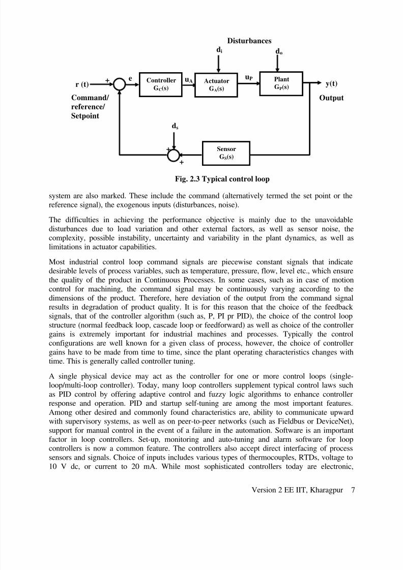
Fig. 2.3 Typical control loop
r (t)
Sensor
GS(s)
ds
di do
uPe +
+
+
Controller
GC(s)y(t)
Plant
GP(s)Actuator
GA(s)
uA
Command/ reference/
Setpoint
Disturbances
Output
system are also marked. These include the command (alternatively termed the set point or thereference signal), the exogenous inputs (disturbances, noise).
The difficulties in achieving the performance objective is mainly due to the unavoidable
disturbances due to load variation and other external factors, as well as sensor noise, the
complexity, possible instability, uncertainty and variability in the plant dynamics, as well aslimitations in actuator capabilities.
Most industrial control loop command signals are piecewise constant signals that indicatedesirable levels of process variables, such as temperature, pressure, flow, level etc., which ensure
the quality of the product in Continuous Processes. In some cases, such as in case of motion
control for machining, the command signal may be continuously varying according to the
dimensions of the product. Therefore, here deviation of the output from the command signalresults in degradation of product quality. It is for this reason that the choice of the feedback
signals, that of the controller algorithm (such as, P, PI pr PID), the choice of the control loop
structure (normal feedback loop, cascade loop or feedforward) as well as choice of the controllergains is extremely important for industrial machines and processes. Typically the control
configurations are well known for a given class of process, however, the choice of controller
gains have to be made from time to time, since the plant operating characteristics changes withtime. This is generally called controller tuning.
A single physical device may act as the controller for one or more control loops (single-loop/multi-loop controller). Today, many loop controllers supplement typical control laws such
as PID control by offering adaptive control and fuzzy logic algorithms to enhance controller
response and operation. PID and startup self-tuning are among the most important features.
Among other desired and commonly found characteristics are, ability to communicate upwardwith supervisory systems, as well as on peer-to-peer networks (such as Fieldbus or DeviceNet),
support for manual control in the event of a failure in the automation. Software is an important
factor in loop controllers. Set-up, monitoring and auto-tuning and alarm software for loopcontrollers is now a common feature. The controllers also accept direct interfacing of process
sensors and signals. Choice of inputs includes various types of thermocouples, RTDs, voltage to
10 V dc, or current to 20 mA. While most sophisticated controllers today are electronic,
Version 2 EE IIT, Kharagpur 7

8/14/2019 L-02(SM)(IA&C) ((EE)NPTEL)
http://slidepdf.com/reader/full/l-02smiac-eenptel 8/21
pneumatic controllers are still being used. Pneumatic controllers are easy to use, easy to
maintain, and virtually indestructible.
Point to Ponder: 3
A. Draw the block diagram of a typical industrial control system
B. Consider a motor driven position control system, as commonly found in CNC Machine
drives. Identify the main feedback sensors in the system. Identify the major sources of
disturbance. How is such a drive different from that of an automated conveyor system?
Sequence / Logic Control
Many control applications do not involve analog process variables, that is, the ones which canassume a continuous range of values, but instead variables that are set valued, that is they only
assume values belonging to a finite set. The simplest examples of such variables are binary
variables, that can have either of two possible values, (such as 1 or 0, on or off, open or closed
etc.). These control systems operate by turning on and off switches, motors, valves, and otherdevices in response to operating conditions and as a function of time. Such systems are referred
to as sequence/logic control systems. For example, in the operation of transfer lines and
automated assembly machines, sequence control is used to coordinate the various actions of theproduction system (e.g., transfer of parts, changing of the tool, feeding of the metal cutting tool,
etc.).
There are many industrial actuators which have set of command inputs. The control inputs tothese devices only belong to a specific discrete set. For example in the control of a conveyor
system, analog motor control is not applied. Simple on-off control is adequate. Therefore for this
application, the motor-starter actuation system may be considered as discrete having threemodes, namely, start, stop and run. Other examples of such actuators are solenoid valves,
discussed in a subsequent lesson.Similarly, there are many industrial sensors (such as, Limit Switch / Pressure Switch/ Photo
Switch etc.) which provide discrete outputs which may be interpreted as the presence/absence of an object in close proximity, passing of parts on a conveyor, or a given pressure value being
higher or lower than a set value. These sensors thus indicate, not the value of a process variable,
but the particular range of values to which the process variable belongs.A modern controller device used extensively for sequence control today in transfer lines,
robotics, process control, and many other automated systems is the Programmable Logic
Controller (PLC). In essence, a PLC is a special purpose industrial microprocessor based real-time computing system, which performs the following functions in the context of industrial
operations
Point to Ponder: 4
A. State the major aspect in which sequence/logic control systems differ from analog control
systems
B. Describe an industrial system that employs discrete sensors and discrete actuators.
Version 2 EE IIT, Kharagpur 8

8/14/2019 L-02(SM)(IA&C) ((EE)NPTEL)
http://slidepdf.com/reader/full/l-02smiac-eenptel 9/21
Supervisory Control
Supervisory control performs at a hierarchically higher level over the automatic controllers,
which controls smaller subsystems.
Supervisory control systems perform, typically the following functions:
♦ Set point computation: Set points for important process variables are computeddepending on factors such as nature of the product, production volume, mode of
processing. This function has a lot of impact on production volume, energy and quality
and efficiency.
♦ Performance Monitoring / Diagnostics: Process variables are monitored to check forpossible system component failure, control loop detuning, actuator saturation, process
parameter change etc. The results are displayed and possibly archived for subsequent
analysis.
♦ Start up / Shut down / Emergency Operations : Special discrete and continuous control
modes are initiated to carry out the intended operation, either in response to operatorcommands or in response to diagnostic events such as detected failure modes.
♦ Control Reconfiguration / Tuning: Structural or Parametric redesign of control loops are
carried out, either in response to operator commands or in response to diagnostic eventssuch as detected failure modes. Control reconfigurations may also be necessary to
accommodate variation of feedback or energy input e.g. gas fired to oil fired.
♦ Operator Interface: Graphical interfaces for supervisory operators are provided, formanual supervision and intervention.
Naturally, these systems are dependent on specific application processes, in contrast with
automatic control algorithms, which are usually generic (e.g. PID). Computationally these are amixture of hard and soft real time algorithms. These are also often very expensive and based onproprietary knowledge of automating specific classes of industrial plants.
Point to Ponder: 5
A. State three major functions of a Supervisory Control System
B. Consider the motor driven automatic position control system, as commonly found in CNC
Machine drives. Explore and find out from where such systems get their set points during
machining. Identify some of the other functionalities
Level 3: Production Control
Production control performs at a hierarchically higher level over the supervisory controllers.Typical functions they perform are:
♦ Process Scheduling: Depending on the sequence of operations to be carried on theexisting batches of products, processing resource availability for optimal resourceutilization.
Version 2 EE IIT, Kharagpur 9

8/14/2019 L-02(SM)(IA&C) ((EE)NPTEL)
http://slidepdf.com/reader/full/l-02smiac-eenptel 10/21
♦ Maintenance Management: Decision processes related to detection and deployment of maintenance operations.
♦ Inventory Management: Decision processes related to monitoring of inventory status
of raw material, finished goods etc. and deployment of operations related to theirmanagement.
♦
Quality Management : Assessment, Documentation and Management of Quality
Typically, the algorithms make use of Resource Optimisation Technology and are non-real-timealthough they may be using production data on-line.
Point to Ponder: 6
A. State three major functions of a Production Control System
B. Explore and find out concrete activities for production control under at least two of the
above major functions in any typical factory such as a Power Plans or a Steel Plant.
The Architecture of Elements: The Automation Pyramid
Industrial automation systems are very complex having large number of devices with
confluence of technologies working in synchronization. In order to know the performance of the
system we need to understand the various parts of the system. Industrial automation systems areorganized hierarchially as shown in the following figure.
Enterprise
Productio
n
Control
Supervisory
Control
Automati
c
Control
SensorsActuator
s
Process /
Level 4
Level 3
Level 2
Level 1
Level 0
Industrial Auto
Industrial
IT
Fig. 2.4 Automation pyramid
Version 2 EE IIT, Kharagpur 10

8/14/2019 L-02(SM)(IA&C) ((EE)NPTEL)
http://slidepdf.com/reader/full/l-02smiac-eenptel 11/21
Various components in an industrial automation system can be explained using the automation
pyramid as shown above. Here, various layers represent the wideness ( in the sense of no. of
devices ), and fastness of components on the time-scale.
Sensors and Acuators Layer: This layer is closest to the proceses and machines, used totranslate signals sothat signals can be derived from processes for analysis and decisions and
hence control signals can be applied to the processes. This forms the base layer of the pyramid
also called ‘level 0’ layer.
Automatic Control Layer: This layer consists of automatic control and monitoring systems,which drive the actuators using the process information given by sensors. This is called as ‘level
1’ layer.
Supervisory Control Layer: This layer drives the automatic control system by setting target/goal
to the controller. Supervisory Control looks after the equipment, which may consis of severalcontrol loops. This is called as ‘level 2’ layer.
Production Control Layer: This solves the decision problems like production targets, resource
allocation, task allocation to machines, maintenance management etc. This is called ‘level 3’
layer.
Enterprise control layer: This deals less technical and more commercial activities like supply,demand, cash flow, product marketing etc. This is called as the ‘level 4’ layer.
The spatial scale increases as the level is increased e.g. at lowest level a sensor works in asingle loop, but there exists many sensors in an automation system which will be visible as the
level is increased. The lowest level is faster in the time scale and the higher levels are slower.
The aggregation of information over some time interval is taken at higher levels.
All the above layers are connected by various types of communication systems. For example thesensors and actuators may be connected to the automatic controllers using a point-to-point digital
communication, while the automatic controllers themselves may be connected with the
supervisory and production control systems using computer networks. Some of these networksmay be proprietary. Over the last decade, with emergence of embedded electronics and
computing, standards for low level network standards (CANBus, Fieldbus etc.) forcommunication with low level devices, such as sensors and actuators are also emerging.
Point to Ponder: 7
A. Draw the Automation Pyramid and identify the Layers
B. Give examples of the above major functional layers in any typical factor. .
A concrete example of the Automation Functionality in a large manufacturing plant is presented
in the appendix below. The appendix reveals the nature of functionality expected in modern
automation systems, the elements that are used to realise them, and the figures of merit for suchsystems. The learner is encouraged to study it.
Version 2 EE IIT, Kharagpur 11

8/14/2019 L-02(SM)(IA&C) ((EE)NPTEL)
http://slidepdf.com/reader/full/l-02smiac-eenptel 12/21
Appendix: An Example Industrial Specification for Automatic andSupervisory Level Automation Systems
This appendix contains the specification of a section of a Cold Rolling Mill complex, referred to
here as PL-TCM which stands for Pickling Line and Tandem Control Mill. Such specification
documents are prepared when automation systems for industrial plants are procured and
installed. The document captures the visualisation of automation functionality of the customer.Here basic level refers to the automatic control supervisory control levels, while process control
level refers to a level. Some of the terms and concepts described below have been discussed insubsequent lessons.
Platforms: The above levels of controls shall be achieved through programmable controllersPLCs, micro-processor based systems as well as PCs / Work stations, as required.
Each of the automation systems of the PL-TCM shall be subdivided in accordance with the
functional requirements and shall cover the open loop and closed loop control functions of thedifferent sections of the line and the mill.
Modes of Operation: The systems shall basically have two modes of operation. In the semi-automatic mode the set point values shall be entered manually for different sections of the line
through VDU and the processors shall transmit these values to the controls in proper time
sequence. In fully automatic mode the process control system shall calculate all set point valuesthrough mathematical models and transfer the same to the subordinate systems over data link.
The functions to be performed by the basic level automation shall cover but not be limited to
the following.
Functionality at Basic Level: The Basic Level shall cover control of all equipment, sequencing,
interlocking micro-tracking of strip for specific functions, dedicated technological functions,storage of rolling schedules and look-up tables, fault and event logging etc. Some of these are
mentioned below.
♦ All interlocking and sequencing control of the machinery such as for entry and exithandling of strips, shear control etc. Interlocking, sequencing, switching controls of the
machines. This shall also cover automatic coil handling at the entry and exit sides,
automatic sequencial operation of welding/rewelding machine and strip threadingsequence control as well as for acid regeneration plant.
♦ Calculation of coil diameter and width at the entry pay-off reels.
♦ Position control of coil ears for centrally placing of coils on the mandrels.
♦ Generation of master speed references for the line depending on operator's input and lineconditions and down loading to drive control systems.
♦ Speed synchronising control of the drives, as required.
♦ Strip tenstion, position and catenary control through control of related drives and
machinery.
Version 2 EE IIT, Kharagpur 12

8/14/2019 L-02(SM)(IA&C) ((EE)NPTEL)
http://slidepdf.com/reader/full/l-02smiac-eenptel 13/21
♦ Initiation of centre position control for Power Operated Rolls, steering/dancer rolls;Looper car position control. Automatic pre-setting control, measurement and control of
tension and elongation for tension leveller. Auto edge position control at tension reels if
required.
♦ Control of entry shear for auto-cutting of off-gauge strip.
♦
Control of pickling parameters for correct pickling with varying speed of strip in thepickling section.
♦ Side trimmer automatic setting contro.
♦ Interlockings, sequencing and control of scrap baller, if provided.
♦ Auto calibration for position control/precision positioning shall be provided as necessary.
♦ Manual/Auto slowdown/stoppage of strip at weld point at tension leveller, side trimmer,
mill and exit shear.
♦ Control of technological functions for tandem mill such as :
o Automatic gauge control along with interst and tension control.
o Shape control
o Roll force control
♦ Storage of tandem mill rolling schedules, for the entire product mix and all possible
variations. Suitable look-up tables as operators guidance for line/equipment setting.
♦ Automatic roll changing along with automatic spindle positioning.
♦ Constant pass line control based on roll wear as well as after roll change.
♦ Automatic control of rotary shear before tension rells.
♦ Automatic sequence control of inspection reel.♦ Provision of manual slow down/stoppage of strip as well as chearing for `run' for
inspection of defects at tension leveller, side trimmer entry and exit of the Tandem
Mill throuth push button stations.
♦ Micro-tracking of strip and flying gauge change (set point change) for continuousoperation with varying strip sizes.
♦ Setting up the mill either from the stored rollings schedule with facility for modificationby the operator of down-loading from process control level system.
♦ Automatic control of in-line coil weighing, marking and circumferential banding after
delivery tension reels.
Supervisory Functions at Basic Level : Centralised supervisory and monitoring control system
shall be provided under basic level automation with dedicated processors and MMI. All
necessary signals shall be acquired through drive control system as well as directly from thesensors/instruments as, required. The system shall be capable of carrying out the following
fuctions.
Version 2 EE IIT, Kharagpur 13

8/14/2019 L-02(SM)(IA&C) ((EE)NPTEL)
http://slidepdf.com/reader/full/l-02smiac-eenptel 14/21
♦ Centralised switching and start up of various line drives and auxiliary systems throughmimic displays.
♦ Status of plant drives and electrical equipment for displaying maintenance information.
♦ Monitoring and display of measured values for tandem mill main drives and other
large capacity drives such as winding temperature, for alarm and trip conditions.
♦ Centralised switching and status indication of 33 kV and 6.6 kV switchboards.
♦ Display of single line diagram of 33 kV and 6.6 kV switchboards, main drives, in-line
auxiliary drives etc.
♦ Acquisition of fault signals from various sections of the plant with facility for displayand print-out of the fault messages in clear text.
Comprehensive diagnostic functions
Functionality at Process Control Level : The Process Control Level shall be responsible forcomputation and control for optimization of operation. Functions like set point generation
using mathematical models, learning control, material tracking within the process line/unitincluding primary data input, real time control of process functions through basic level
automation, generation of reports etc. shall be implemented through this level of automation.
Some of the specific functions to be performed by the process control level automation are thefollowing.
♦ Coil strip tracking inside the process line/unit by sensing punched holes at weld seams.
♦ Primary Data Input (PDI) of coils at entry to PL-TCM with provision for down loadingof data from production control level.
♦ Generation of all operating set points for the mill using PDI data, mill model, rollforce model, power model, strip thickness control model, shape/profile control model
with thermal strip flatness control as well as for other sections of the line.
♦ Learning (Adaptive) control using actual data and the mathematical model for set-up
calculations.
♦ Storage of position setting values of levellers, side trimmer. Input of strip flaw datamanually through inspection panel at the inline inspection facility after side trimmer.
♦ Processing of actual data on rolling operation, generation of reports logs and sending
data to production control level.
Information System Functions: The information system shall generally comply with thefollowing features.
♦ Data of importance shall be available with the concerned personnel in the form of logsand reports.
♦ Output of logs and reports at preset times or on occurance of certain events.
♦ It shall be possible to change the data items and log formats without undue interferenceto the system.
Version 2 EE IIT, Kharagpur 14
8/14/2019 L-02(SM)(IA&C) ((EE)NPTEL)
http://slidepdf.com/reader/full/l-02smiac-eenptel 15/21
♦ Logged information shall be stored for adequate time period ensuring the availability of historical data record.
♦ Data captured by the system shall be checked for integrity with respect to their validity
and plausibility with annunciation.
Man Machine Interface: The visualisation system for both the automation levels shall be
through man-machine interface (MMI) for the control and operation of the complete line. Thesystem shall display the following screens, with facilities for hard copy print out.
♦ Process mimics for the complete line using various screens with status information of
all important in-line drives as well as the references and actual values of importantparameters.
♦ Dynamic information’s in form of bar graph for indication of reference and actual valuesof important parameters.
♦ Screens providing trends of the important process variables.
♦
Acquisition of actual parameters (averaging/maximum/minimum) for the complete line,on coil to coil basis through weld seam tracking or TCM exit shear cut for the generationof logs on process/parameters and production.
Standards: The programmable controllers and other micro processor based equipment offeredshall generally be designed/structured, manufactured and tested in accordance with the
guidelines laid down in IEC-1131 (Part 2) apart from the industry standards being adopted by the
respective manufactures.
Hardware: The hardware of each basic controller/equipment of a system will generally
comprise main processing unit, memory units, stabilised power supply unit, necessary
communication interface modules, auxiliary storage where required. I/O modules in the mainequipment, remote I/O stations where required and the programming and debugging tool
(PADT). The hardware and software structure shall be modular to meet wide range of
technological requirements. I/Os shall be freely configurable depending on the requirement.The programming units shall preferable be lap-top type.
Networking: The networking would conform to the following specifications.
♦ In each of the two automation levels, all the controllers of a system shall be connected
as a node over suitable data bus forming a LAN system using standardised hardware
and software.
♦ The LAN system shall be in line with ISO-Open system Interconnect.
♦ All drive level automation equipment shall be suitably linked with the basic level for
effective data/signal exchange between the two levels. However, all the emergencyand safety signals shall be directly hardwired to the respective controllers.
♦ Similarly, the LAN systems for the basic level and process control level shall besuitably linked through suitable bridge/interface for effective data/signal exchange.
Provision shall also be made for interfacing suitably the process control level with the
production level automation system specified in item .
Version 2 EE IIT, Kharagpur 15

8/14/2019 L-02(SM)(IA&C) ((EE)NPTEL)
http://slidepdf.com/reader/full/l-02smiac-eenptel 16/21
♦ The data highways shall be designed to be optimally loaded and the same shall be clearlyindicated in the offer.
♦ The remote I/Os, the microprocessor based measuring instruments and the micro-
processor based special machines like coil weighing, marking and circumferantialbanding machines shall be connected over serial links with the respective controllers.
♦
The personal computers and work stations shall be connected as a LAN system of thecorresponding level.
Data and Visualisation: The following specifications would apply in respect of data security,
validity and its proper visualisation.
♦ All the operator interfaces comprising colour VDU and keyboard as MMI for interactingwith the respective system and located at strategic locations, shall be connected to the
corresponding LAN system.
♦ Keylock/password shall be provided to prevent unauthorised entry.
♦
Entry validity and plansibility check shall also be incorporated.♦ An Engineer's console comprising of necessary processor, color VDU, keyboard/mouse
and a printer unit shall be provided for the automation systems. The console shall havenecessary hardware and software of communicating with the LAN and shall have access
to the complete system. Basic functions of this console shall be off-line data base
configuration, programme development, documentation etc.
Application Software: The application software shall be through functional block type software
modules as well as high level language based software modules. The software shall be userfriendly and provided with help functions etc. Only one type of programming language shall be
used for the complete system. However, ladder type programming language may be used for
simple logical functions. Only industrially debugged and tested software shall be provided.
Basis of System Selection
Future Expandibility: The selection of equipment, standard software and networking shall besuch as to offer optimum flexibility for future expansion without affecting the system reliability.
Fault Tolerance: The system shall be designed to operate in automatic or semi automatic mode
of operation under failure conditions.
Spare Capacity: The system shall have sufficient capacity to perform all functions as required.
A minimum of 30 per cent of the total memory shall be kept unallocated for future use.
Loading: The data highway shall be designed to be optimally loaded and the same shall be
clearly indicated in the offer.
Software Structure and Quality Programs: shall be in high level language that is effective andeconomical for the proposed system in respect of Modularisation, rate of coding, store usage
and running time. The software structure of the system shall besuitably distributed/centralised for
supervision and control of the related process areas following the state of the artarchitecture.
Version 2 EE IIT, Kharagpur 16

8/14/2019 L-02(SM)(IA&C) ((EE)NPTEL)
http://slidepdf.com/reader/full/l-02smiac-eenptel 17/21
Integration: The communication software shall be such that the systems shall be able to
communicate independently among themselves as well as with the lower level Basic
Control/Process control automation system, as required. Provision shall be made for interfacing
the production control system with the higher level Business Computer system to be provided forthe entire steel plant in future.
Programmability: The information system shall generally be designed such that it shall be
possible to change the data items and log formats without undue interference to the system.
Data Integrity and Protection: Logged information shall be stored for adequate time periodensuring the availability of historical data record. Data captured by the system shall be checked
for integrity with respect to their validity and plausibility with annunciation. Storing of
essential data to be protected against corruption when the system loses power supply or
during failure.
Point to Ponder: 8
A. State three major functions of Supervisory Control mentioned in the lesson that have also
been mentioned in the Automation System for the PL-TCM. B. State three major figures of merit for an Automation System mentioned in the appendix
PL-TCM.
Version 2 EE IIT, Kharagpur 17
8/14/2019 L-02(SM)(IA&C) ((EE)NPTEL)
http://slidepdf.com/reader/full/l-02smiac-eenptel 18/21
Answers, Remarks and Hints to Points to Ponder
Point to Ponder: 1
Draw the functional block diagram of a typical sensor system
Ans: The diagram is given in Fig. 2.1.in the lesson.
Consider a strain-gage weigh bridge. Explore and identify the subsystems of the bridge and
categorise these subsystems into the above mentioned classes of elements mentioned above
Ans: A strain gage weighbridge contains the weighing platform and pillar, which senses theweight and produces a proportional strain (sensing element 1). This strain is sensed by a
strain-gage which produces a proportional change in resistance (sensing element 2). The gage
is incorporated into a Wheatstone’s bridge circuit (Signal conditioning) which generates a
proportional unbalanced voltage.
Point to Ponder: 2 A. Draw the functional block diagram of an actuator system
Ans: The diagram is given in Fig. 2.1.in the lesson.
B. Consider an electro-hydraulic servo-valve actuator. Explore and identify the subsystems
of the actuator and categorise these subsystems into the above-mentioned classes of
elements mentioned above.
Ans: An electrohydraulic servo valve is driven by current through a solenoid, which moves
the spool of the valve, by applying a voltage across it. The voltage is derived by anelectronic controller (electronic signal processing element), which gives a voltage input that
is amplified by a servo amplifier (electronic power amplification element). The force due to
the current produces motion of the spool (variable conversion element), which is converted topressure (non electrical power conversion element) within the servo valve and applied to the
final control element. Miscellaneous elements, such hydraulic system auxiliaries, indicators
etc. are also present
Point to Ponder: 3
A. Draw the block diagram of a typical industrial control system
Ans: The diagram is given in Fig. 2.3 in the lesson.
B. Consider a motor driven position control system, as commonly found in CNC Machine
drives. Identify the main feedback sensors in the system. Identify the major sources of
disturbance. How is such a drive different from that of an automated conveyor system?
Ans: Many examples can be given. One of these is the following:
Version 2 EE IIT, Kharagpur 18

8/14/2019 L-02(SM)(IA&C) ((EE)NPTEL)
http://slidepdf.com/reader/full/l-02smiac-eenptel 19/21
In an industrial CNC machine, the motion control of the spindle, the tool holder and the job table
are controlled by a position and speed control system, which, in fact, uses a position sensor such
as shaft angle encoder or resolver, speed sensors such analog or digital tachometers and current
sensors such Hall-effect sensors.The major sources of disturbances are changes in load torque arising in the machine due to
material inhomogenity, tool wear etc.
While both drives use motors for creating displacements, conveyor drives have very littledemand on position and speed accuracy requirements. On the contrary there are very stringent
requirement on these in the case of the CNC Machine.
Point to Ponder: 4
State the major aspect in which sequence/logic control systems differ from analog control
systems
Ans: The two major aspects in which they differ is in the nature of sensor inputs and the actuatoroutputs. These are discrete elements in the case of logic Control (on-off, low-high-medium etc.)
and continuous valued in case of analog control. Similarly for actuator output (motor start/stop).The controller outputs are generally functions of inputs and feedback.
Describe an industrial system that employs discrete sensors and discrete actuators.
Ans: There are many such systems. For example a diecasting process is shown below. This
process example is dealt with further in other lessons.
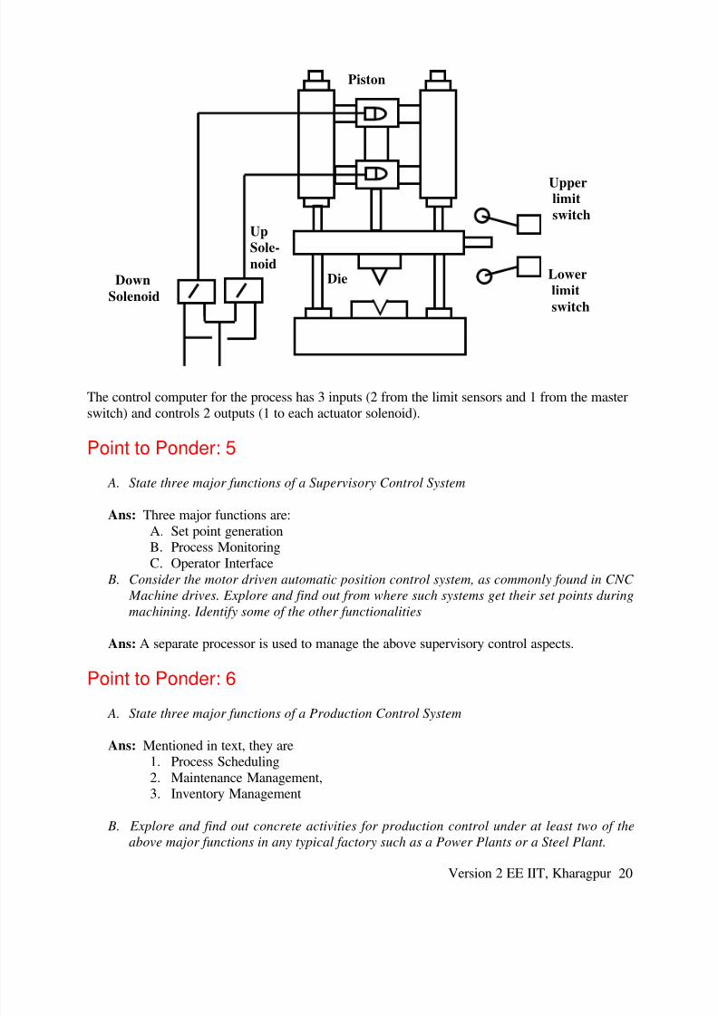
Industrial Example
The die stamping process is shown in figure below. This process consists of a metal stamping die
fixed to the end of a piston. The piston is extended to stamp a work piece and retracted to allowthe work piece to be removed. The process has 2 actuators: an up solenoid and a down solenoid,
which respectively control the hydraulics for the extension and retraction of the stamping piston
and die. The process also has 2 sensors: an upper limit switch that indicates when the piston isfully retracted and a lower limit switch that indicates when the piston is fully extended. Lastly,
the process has a master switch which is used to start the process and to shut it down.
Version 2 EE IIT, Kharagpur 19
8/14/2019 L-02(SM)(IA&C) ((EE)NPTEL)
http://slidepdf.com/reader/full/l-02smiac-eenptel 20/21

8/14/2019 L-02(SM)(IA&C) ((EE)NPTEL)
http://slidepdf.com/reader/full/l-02smiac-eenptel 21/21
Ans: Power plants do not have product variety. However, heavy maintenance activity goes
on round the year. There is also significant inventory management for the Coal Yard.
Point to Ponder: 7
A. Draw the Automation Pyramid and identify the Layers
Ans: The diagram is given in Fig. 2.4.in the lesson.
B. Give examples of the above major functional layers in any typical factory.
Ans: The answer to this question is given in detail in the appendix for a section of a largerolling mill.
Point to Ponder: 8
A. State three major functions of Supervisory Control mentioned in the lesson that have also
been mentioned in the Automation System for the PL-TCM.
Ans: The answer to this question is given in detail in the appendix for a section of a large
rolling mill. In brief three major functions are :
♦ Centralised switching and start up
♦ Monitoring and display of measured values
♦ Comprehensive diagnostic functions
B. State three major figures of merit for an Automation System mentioned in the appendix
PL-TCM.
Ans: Integration, Programmability, Fault tolerance