Embed Size (px)
Citation preview

Lab Procedure: Creating a New MPLAB Project
CTEC1904/2015W Microprocessor Technology
Revision 1.4: January 11, 2015


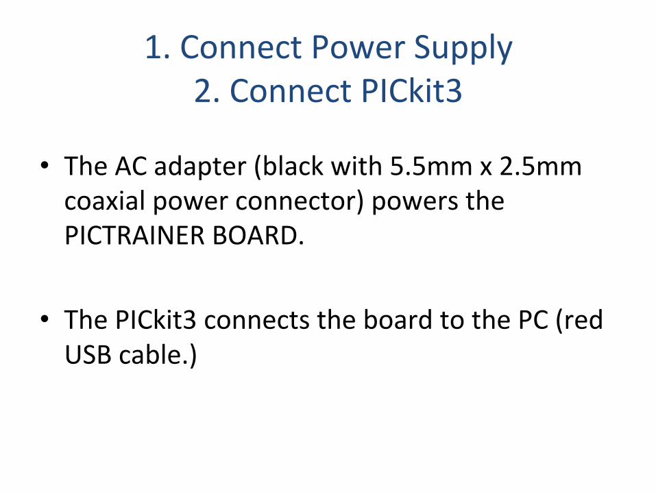
1. Connect Power Supply 2. Connect PICkit3
• The AC adapter (black with 5.5mm x 2.5mm coaxial power connector) powers the PICTRAINER BOARD.
• The PICkit3 connects the board to the PC (red USB cable.)


3. Create Folder
• Use Windows Explorer or the Command Prompt to create a new folder on the Desktop.
• The folder will contain all files required to build and run the project, and can easily be archived (zipped.)

4. Download Program File
• Download either the complete program or the program template from the course web site or from Blackboard, and save it in the new folder.

AlternaXve: Downloading Archive
• SomeXmes, the folder containing a source code file will be available for download.
• Simply download the .zip or .7z file from the course web site or from Blackboard, and save it to the Desktop.
• Right click to run 7-‐Zip to extract both the folder and program file.

5. Open MPLAB IDE
• MPLAB is used to write code, to assemble that code, download machine code to a microcontroller board, and debug the code.
• The easiest way to create a new project is to use the Project menu and choose Project Wizard…

6. MPLAB Project Wizard

MPLAB Project Wizard – Step 1a • First, choose the microcontroller model that you are using.
• The PICTRAINER BOARD has a PIC18F8722.
Note: MPLAB remembers the last microcontroller that was used. When MPLAB was installed, that microcontroller was probably not the PIC18F8722 – typically, either the PIC18F452 or PIC18F4520.

MPLAB Project Wizard – Step 1b
1
2
3

MPLAB Project Wizard – Step 2
• We are programming in assembly language. The default “Toolsuite” is the assembler.

MPLAB Project Wizard – Step 3a
1
2
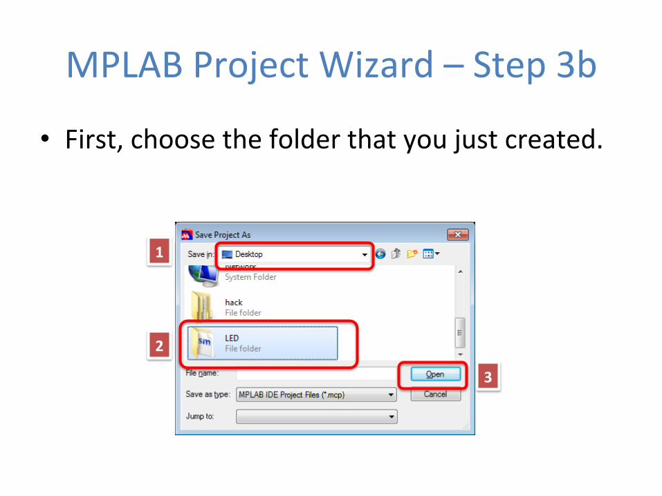
MPLAB Project Wizard – Step 3b
• First, choose the folder that you just created.
1
2
3

MPLAB Project Wizard – Step 3c • Then, name the project. If you use the same name as the program file, do not add the .asm extension. Acer typing in the project name, click Save.
1 2

MPLAB Project Wizard – Step 3d
• MPLAB will then show the full pathname to the project file. Click Next.

MPLAB Project Wizard – Step 4a • Click on the program (.asm) file on the lec side, then click Add>> to add it to the project. (See the next slide for an “A3er” shot.)
1
2
3

MPLAB Project Wizard – Step 4b • Before you click Next, this is what the window will look
like…

MPLAB Project Wizard – Done
• MPLAB will display the summary. Click Finish.

Title bar with open workspace indicated Menu bar
Tool bar
Output Window
Status bar
Project window

Debugger • Work in MPLAB normally involves using a Debugger device
to develop a program, then a Programmer device (typically the same device) to upload the finished product (called a Release.)
• We are using the PICkit 3 device, which can be used as both a Programmer and a Debugger.
1 2
3

Debugger -‐ Warning • The “Voltage CauXon” warning box can be safely ignored.
(The PICTRAINER BOARD circuit is designed correctly.)
• Check “Don’t show me this again” … but you have to do this with each new project.
1
2

Debugger -‐ Comms
• Acer you select the PICkit 3 as a debugger, a “PICkit 3” tab will be created in the Output window and MPLAB will agempt to communicate with the device… you should see “PICkit 3 Connected”
Note: If you DON’T see this, you should exit MPLAB and try a different USB port, then restart MPLAB. If it sXll doesn’t work, try rebooXng.

Edit Source • If you double-‐click the .asm file in the Project window, it will open the program in a Source window, so that you may view and edit the code.

Editor Seings
• Edit | ProperXes (from the Menu bar)
1
2 3
4
5
6
7
8
Note: these are the recommended seings to use for programs in this course.

Editor Seings
(I prefer the Consolas font, 14pt., Bold, but choose whatever works for you.)

Absolute Code GeneraXon • To assemble the program, click Build All from the Tool bar. • The first Xme, MPLAB will ask if you want Absolute or Relocatable
code. • Choose Absolute, because our programs are simple and are stored
in a single .asm file.
1
2

Build • “Build All”
causes the assembler to translate the assembly code into PIC machine code.
• You will see various messages in the “Build” tab of the Output window, but “BUILD SUCCEEDED” is the important one.
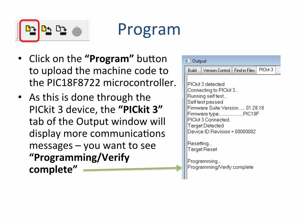
Program • Click on the “Program” bugon to upload the machine code to the PIC18F8722 microcontroller.
• As this is done through the PICkit 3 device, the “PICkit 3” tab of the Output window will display more communicaXons messages – you want to see “Programming/Verify complete”

Run • The “Run” bugon on the Tool bar starts the program on the microcontroller.
• You should see various things: – The “Running…” message in the “PICkit 3” tab of the output window
– A “Running…” animaXon in the Status Bar
– A green arrow in the Source window, poinXng at the first instrucXon in the program
– Most importantly, you should see the PICTRAINER BOARD doing something!

Halt • Halt is used to stop the program. • MPLAB shows you at which line the program was halted.

Step
• Two commands: – Step Into [F7] – Step Over [F8]
• Allow you to execute one instrucXon at a Xme
• The green arrow tracks the instrucXon

Step (2)

Step (3)
• Single-‐stepping is a useful debugging task, to help diagnose a program that is not working correctly.

Watch
• Use a WATCH LIST containing only the registers of interest (including any SFRs like W)
• Fast updaXng since only a few registers are interrogated
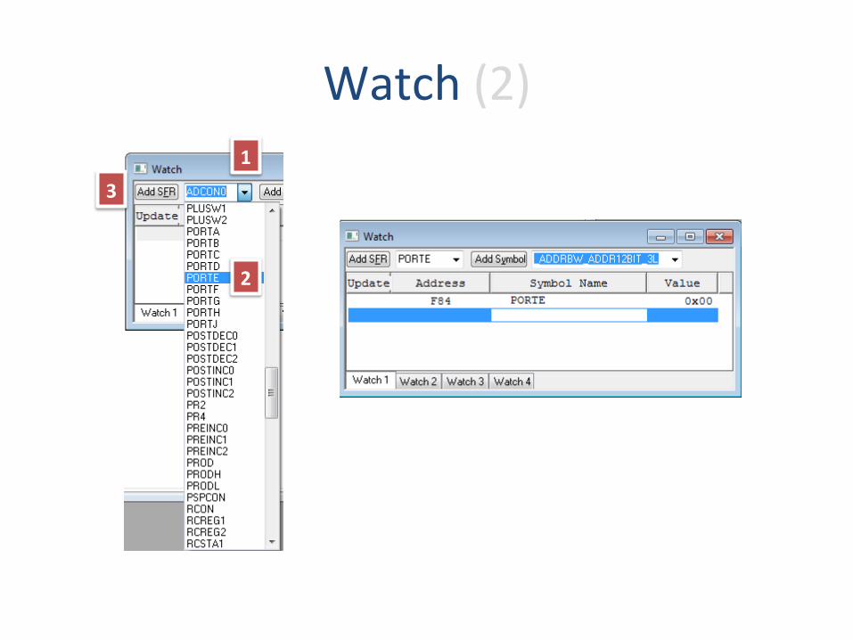
Watch (2) 1
2
3

Watch (3)
• You can change the display format of each watch register (default is hexadecimal) -‐> right click and select ProperWes.
• You can change every register you want to change before clicking OK.
• AlternaXvely, you can add columns (mulXple number formats) by right-‐clicking on the column headings.
1 -‐ RC
2
3 -‐ single, 4 -‐ mulWple
3 -‐ mulWple

Watch and Step
• Watch is parXcularly useful when combined with single stepping. • Cool feature: each Xme a register value changes it appears in red instead
of black

Step and Watch (1)
• As you step, the registers are updated by MPLAB.
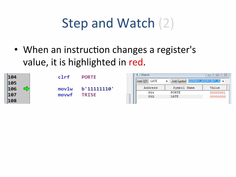
Step and Watch (2)
• When an instrucXon changes a register's value, it is highlighted in red.

Step and Watch (3)

Breakpoints • Can also set BREAKPOINTS where code runs at full-‐speed to
this point and then halts allowing registers to be interrogated
• Just double-‐click on a line of code to put a breakpoint there

Oops! • MPLAB colours each recognized PIC instrucXon in blue. If
you make a mistake, it will remain coloured in purple.

Build Failed!
• Any syntax errors in the code will prevent the project from building!

Build Failed!
• You can double-‐click on each Error or Warning message, and MPLAB will take you to the offending line of code.

Done
• When you are done working, choose File | Close Workspace from the menu.
• If any of the project files need saving, MPLAB will noXfy you.

The Complete Project
• MPLAB creates about 9 files for each project. It's important to keep them all together.

Make A Backup! • Since everything is in one folder, it is easy to make a backup with 7-‐Zip.
Don't forget to copy the backup to non-‐vola,le media, i.e., NOT on C drive in the lab, because DeepFreeze will wipe it out.
• 7-‐Zip compresses the projects around 95%!