Embed Size (px)
Citation preview
Laboratory Manual
Fiber Optics
Revised September, 2009
Lab Manual.doc, 7/2/16, 1
Laboratory Manual Handson Fiber Optic Training
Section Page Laboratory Guidelines 3 Safety 4 Fiber Optic Cables 7 Cable Ratings and Markings 13 Zipcord 13 Breakout and Distribution 14 Pulling Cable 18 Double Jacket Loose Tube 18 Loose Tube 19 Armored 20 Fiber Optic Cable Termination 24 Splicing 40 Mechanical Splicing 41 Fusion Splicing 45 Fiber Optic Testing 49 Continuity and Visual Fault Location 51 Visual Inspection with Microscope 52 Optical Power 53 Insertion Loss 57 OTDRs 63
Lab Manual.doc, 7/2/16, 2

Laboratory Guidelines ● Read the “Safety Issues” page FIRST carefully and follow it ! EVERYBODY,
including the instructor(s) must wear safety glasses during all labs and follow all other safety procedures.
● Make certain before you begin that you understand the purpose of the exercises and
have everything you need. ● Where listed, view the visual aids, especially the stepbystep “virtual handson”
exercises” on the FOA Online Reference Website before the lab session. ● Allow plenty of time to complete the exercises, especially termination. ● Clean up after your exercises carefully. Some of the scrap you generate can be
harmful, such as fiber scraps, so we recommend you not work anywhere near food preparation or children’s play areas! Place clean paper over your work area to keep from harming the worktable surface.
Lab Manual.doc, 7/2/16, 3
Safety Eye Safety
When one speaks of safety in fiber optic installation, the first image that comes to most people’s minds is a laser burning holes in metal or being used in place of a scapel for surgery. While these images may be real for their applications, they have no relevance to fiber optics. Optical sources used in fiber optics are of much lower power levels and are not focused into a time spot like these applications.
In fact, most data communications links use LEDs or lasers of relatively low power levels. The light that exits an optical fiber is also spreading out in a cone, so the farther away from the end of the fiber you are, the lower the amount of power striking a given sized spot. Furthermore, the light is of a wavelength that cannot penetrate your eye because of the absorption of the water in your eyeball at those wavelengths.
That said, some fiber optic links, like telco dense wavelength division multiplexing systems that may contain power from up to 64 different sources and is even amplified by fiber amplifiers and CATV systems using highpower DFB lasers or optical amps has enough power to be of concern. Also, using a microscope to inspect an operating system can be hazardous as the microscope can concentrate the power into your eye.
One should never look directly at the end of a fiber, especially those in working systems, because the light is infrared and invisible to the eye, so there is no warning of potential damage. On operating systems, always test the power in the fiber before inspecting it with a microscope. Many microscopes have filters to remove harmful levels of infrared light without compromising visibility of fiber defects, but make sure yours has one before trusting it. Video microscopes are also available to inspect operating systems safely.
The FOA reference website has a comprehensive discussion of eye safety. (www.thefoa.org/tech/ref/safety/safe.html) which you and your students should read. A complete eye safety study and report is in ANSI Z136.2. Bare Fiber Safety
Fiber optics installation, however, is not without risks. As part of the termination and splicing process, you will be continually exposed to small scraps of bare fiber cleaved off the ends of the fibers being terminated or spliced. These scraps are very dangerous. If they get into your eyes, they are very hard to flush out. Always wear safety glasses when working with bare fibers. A pair of safety glasses is included in the kit. Use them, keep them clean, and protect them from damage like any other tool.
The cleaved ends are extremely sharp and can easily penetrate your skin! Be careful to not stick the broken ends into your fingers, since they invariably break off and are very hard to find and remove. Most times, you have to wait for them to infect and painfully work themselves out. A pair of tweezers are included in the kit for removing splinters. Carefully pull the glass splinters out before they have a chance to break off and become lodged in the skin.
Lab Manual.doc, 7/2/16, 4
Avoid these painful accidents by exercising a little caution. Dispose of all scraps properly. Keep a piece of double stick tape on the bench to stick them to or put them in a properly marked paper cup or other container to dispose of later. Do not drop them on the floor where they will stick in carpets or shoes and be carried elsewhere. Do not eat anywhere near the work area. Other Considerations for Safety
Fiber optic splicing and termination use various chemical cleaners and adhesives as part of the processes. Normal handling procedures for these substances should be observed. If necessary, download and post MSDS for each substance involved. Even simple isopropyl alcohol, used as a cleaner, is flammable and should be handled carefully. Note: Fusion splicers use an electric arc to make splices, so care must be taken to insure no flammable gasses are present in the space where fusion splicing is done. Note: Installation of fiber optic cabling does not normally involve electrical hazards unless the cable includes conductors. However, these cables are often installed in proximity to electrical and conductive cables. Whenever you are near these cables, there is always a potential shock hazard. Be careful! If you are not familiar with electrical safety, we recommend you take a course on the NEC (National Electrical Code) and safety practices for installers! Below is a page of fiber optic safety rules that should be posted in the lab in a prominent place and reviewed at the beginning of each lab.
Lab Manual.doc, 7/2/16, 5
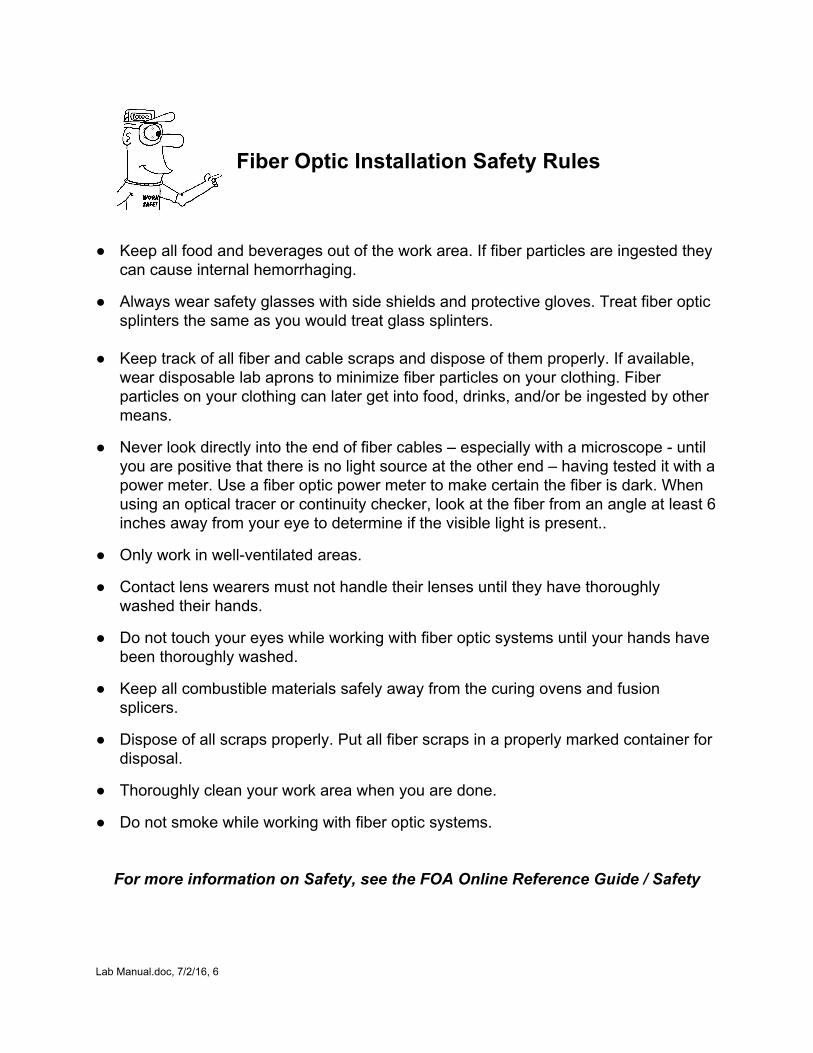
Fiber Optic Installation Safety Rules
● Keep all food and beverages out of the work area. If fiber particles are ingested they
can cause internal hemorrhaging. ● Always wear safety glasses with side shields and protective gloves. Treat fiber optic
splinters the same as you would treat glass splinters. ● Keep track of all fiber and cable scraps and dispose of them properly. If available,
wear disposable lab aprons to minimize fiber particles on your clothing. Fiber particles on your clothing can later get into food, drinks, and/or be ingested by other means.
● Never look directly into the end of fiber cables – especially with a microscope until
you are positive that there is no light source at the other end – having tested it with a power meter. Use a fiber optic power meter to make certain the fiber is dark. When using an optical tracer or continuity checker, look at the fiber from an angle at least 6 inches away from your eye to determine if the visible light is present..
● Only work in wellventilated areas. ● Contact lens wearers must not handle their lenses until they have thoroughly
washed their hands. ● Do not touch your eyes while working with fiber optic systems until your hands have
been thoroughly washed. ● Keep all combustible materials safely away from the curing ovens and fusion
splicers. ● Dispose of all scraps properly. Put all fiber scraps in a properly marked container for
disposal. ● Thoroughly clean your work area when you are done. ● Do not smoke while working with fiber optic systems. For more information on Safety, see the FOA Online Reference Guide / Safety
Lab Manual.doc, 7/2/16, 6
Fiber Optic Cables
What Students Learn: How to use tools needed for cable preparation, splicing and termination How to prepare cables for splicing and termination Exercises:
I. Cable Ratings and Marking II. Pulling Zipcord III. Breakout and Distribution Cables
a. Preparing Breakout Cable for Termination b. Preparing Distribution Cable for Termination or Pulling
IV. Handling and Stripping the Fiber V. Preparing Distribution Cable for Pulling VI. Pulling Cable VII. Dual Jacket Outside Plant Cable VIII. Preparing Single Jacket Loose Tube Cable IX. Preparing Armored Cable
Note: This manual includes instructions for a number of cable types. You may not have all these available, but as a minimum, you should try to use 3mm jacketed tight buffer, distribution, breakout and loose tube cables samples for training. Visual Aids
The following visual aids show the processes described in these exercises. They may be shown to the students before the lab or just used as a reference by the instructor.
FOA PPTs, Cables FOA Online Reference Guide To Fiber Optics: Basics/Cables, Cable VHO FOA Instructional Videos (Online or DVD): Cable Preparation
Safety: All students and instructors must wear safety glasses in this lab. Follow all safety rules for working with fiber. Safely dispose of all fiber and cable scraps after use. Tools and Materials needed: Safety Glasses Miller Jacket stripper Aramid Yarn Scissors Needle Nose Pliers Armored Cable Cutter Large Jacket Slitter and Stripper Fiber Optic Stripper Utility Knife Lab Manual.doc, 7/2/16, 7
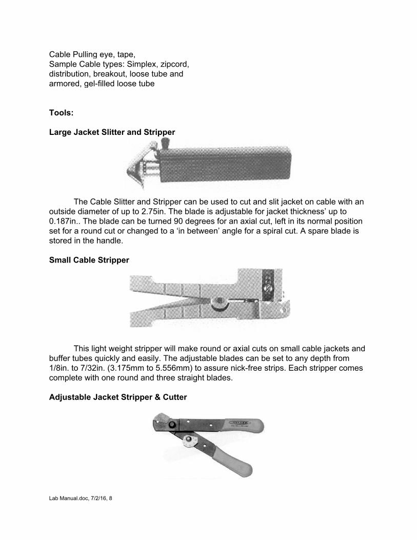
Cable Pulling eye, tape, Sample Cable types: Simplex, zipcord, distribution, breakout, loose tube and armored, gelfilled loose tube Tools: Large Jacket Slitter and Stripper
The Cable Slitter and Stripper can be used to cut and slit jacket on cable with an
outside diameter of up to 2.75in. The blade is adjustable for jacket thickness’ up to 0.187in.. The blade can be turned 90 degrees for an axial cut, left in its normal position set for a round cut or changed to a ‘in between’ angle for a spiral cut. A spare blade is stored in the handle. Small Cable Stripper
This light weight stripper will make round or axial cuts on small cable jackets and buffer tubes quickly and easily. The adjustable blades can be set to any depth from 1/8in. to 7/32in. (3.175mm to 5.556mm) to assure nickfree strips. Each stripper comes complete with one round and three straight blades. Adjustable Jacket Stripper & Cutter
Lab Manual.doc, 7/2/16, 8
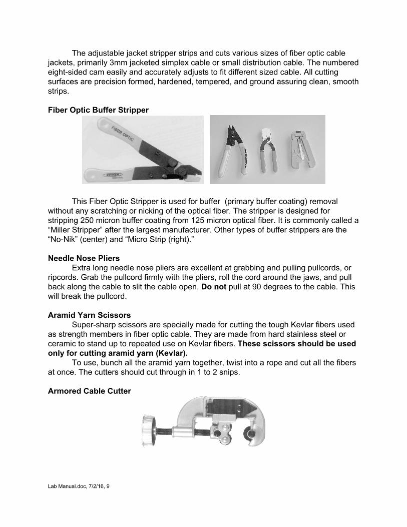
The adjustable jacket stripper strips and cuts various sizes of fiber optic cable jackets, primarily 3mm jacketed simplex cable or small distribution cable. The numbered eightsided cam easily and accurately adjusts to fit different sized cable. All cutting surfaces are precision formed, hardened, tempered, and ground assuring clean, smooth strips. Fiber Optic Buffer Stripper
This Fiber Optic Stripper is used for buffer (primary buffer coating) removal without any scratching or nicking of the optical fiber. The stripper is designed for stripping 250 micron buffer coating from 125 micron optical fiber. It is commonly called a “Miller Stripper” after the largest manufacturer. Other types of buffer strippers are the “NoNik” (center) and “Micro Strip (right).” Needle Nose Pliers
Extra long needle nose pliers are excellent at grabbing and pulling pullcords, or ripcords. Grab the pullcord firmly with the pliers, roll the cord around the jaws, and pull back along the cable to slit the cable open. Do not pull at 90 degrees to the cable. This will break the pullcord. Aramid Yarn Scissors
Supersharp scissors are specially made for cutting the tough Kevlar fibers used as strength members in fiber optic cable. They are made from hard stainless steel or ceramic to stand up to repeated use on Kevlar fibers. These scissors should be used only for cutting aramid yarn (Kevlar).
To use, bunch all the aramid yarn together, twist into a rope and cut all the fibers at once. The cutters should cut through in 1 to 2 snips. Armored Cable Cutter
Lab Manual.doc, 7/2/16, 9

A standard plumbing tubing cutter can be used with larger diameter metallicarmored cables for cutting through both outside jacket and armor. The depth of the cutting blade is generally correct for cutting the outer jacke and armor without harming the inner jack or fibers in an metallicarmored cable. Cut the armor just like tubing, making several revolutions around the cable, tightening the cutters with each revolution.
Lab Manual.doc, 7/2/16, 10
Fiber Optic Cable Preparation
These exercises will show you how to handle fiber optic cables during installation, splicing and termination. Refer to the toolbox manual for tool and instrument instructions. Pulling Cable
In a classroom course, we cannot have you practice “pulling” cables. The main thing to learn is that cable must be pulled ONLY by the strength members provided in the cables, never by the fibers and only special cables can be pulled by the jacket.
If you are ever in doubt about the proper way to pull a specific type of cable, contact an applications engineer at the cable company and get specific instructions. Otherwise you may damage the fibers. Damage to a fiber optic cable is never reversible. If it is damaged, it must be removed and replaced, potentially very expensive!
Preparing Cables for Termination and Splicing
In this course, we describer the use of several common types of cable for practice. These cables are tight buffer, distribution, breakout and loose tube cable typical of cables installed in a network. You use these samples to strip jackets and expose fibers for splicing or termination. Refer to the Toolbox instruction sheets for the tools you will be using.
After working with the samples provided, fill in the worksheet at the end of the section.
Lab Manual.doc, 7/2/16, 11
PreLab Cable Preparation
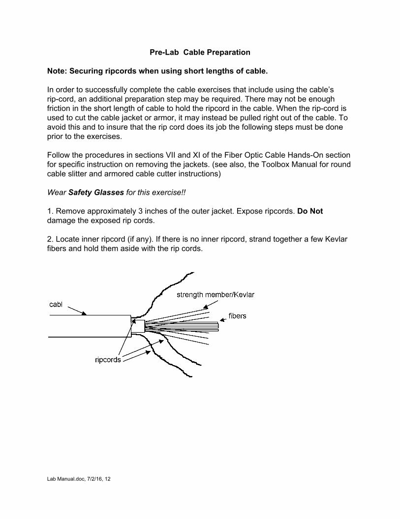
Note: Securing ripcords when using short lengths of cable. In order to successfully complete the cable exercises that include using the cable’s ripcord, an additional preparation step may be required. There may not be enough friction in the short length of cable to hold the ripcord in the cable. When the ripcord is used to cut the cable jacket or armor, it may instead be pulled right out of the cable. To avoid this and to insure that the rip cord does its job the following steps must be done prior to the exercises. Follow the procedures in sections VII and XI of the Fiber Optic Cable HandsOn section for specific instruction on removing the jackets. (see also, the Toolbox Manual for round cable slitter and armored cable cutter instructions) Wear Safety Glasses for this exercise!! 1. Remove approximately 3 inches of the outer jacket. Expose ripcords. Do Not damage the exposed rip cords. 2. Locate inner ripcord (if any). If there is no inner ripcord, strand together a few Kevlar fibers and hold them aside with the rip cords.
Lab Manual.doc, 7/2/16, 12
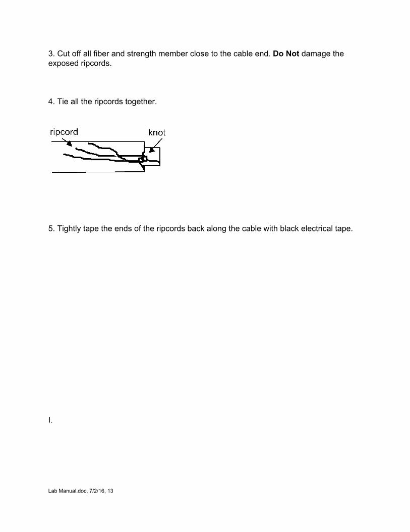
3. Cut off all fiber and strength member close to the cable end. Do Not damage the exposed ripcords. 4. Tie all the ripcords together.
5. Tightly tape the ends of the ripcords back along the cable with black electrical tape.
I.
Lab Manual.doc, 7/2/16, 13
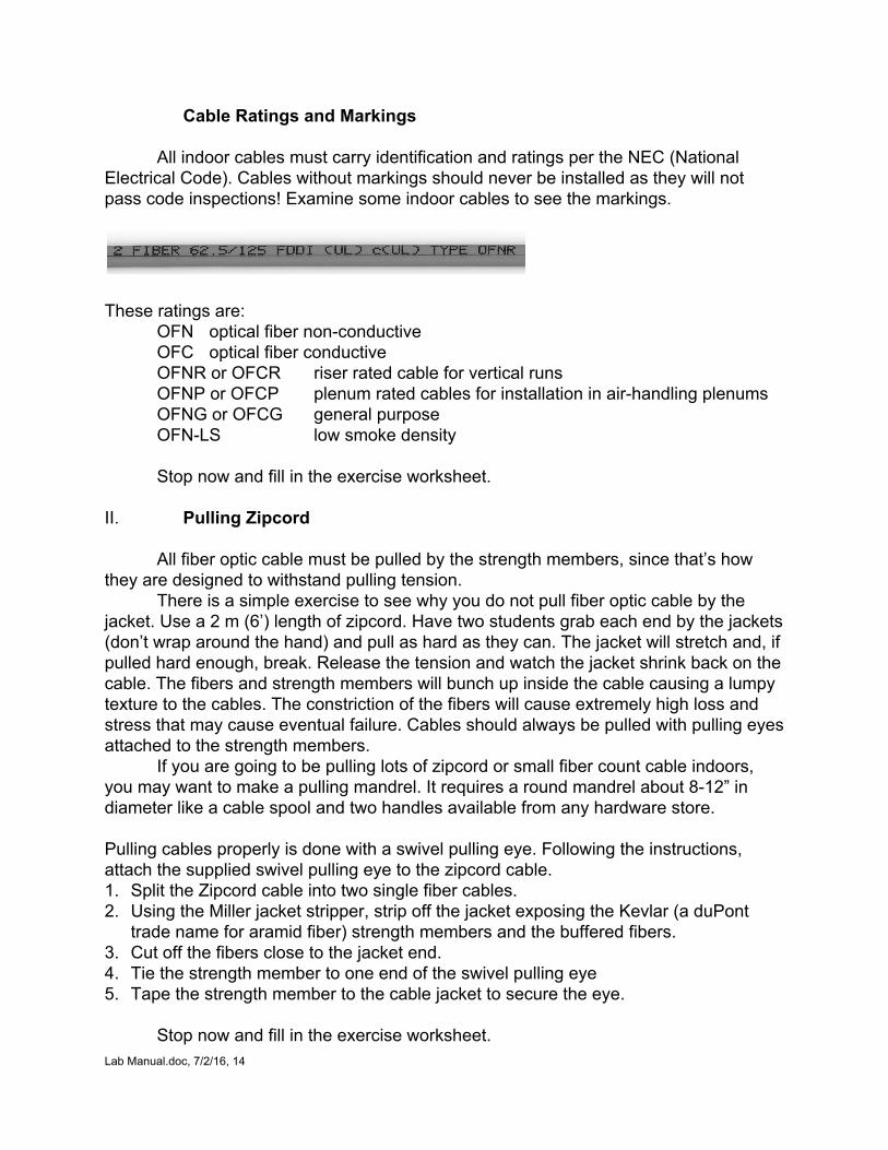
Cable Ratings and Markings
All indoor cables must carry identification and ratings per the NEC (National Electrical Code). Cables without markings should never be installed as they will not pass code inspections! Examine some indoor cables to see the markings.
These ratings are:
OFN optical fiber nonconductive OFC optical fiber conductive OFNR or OFCR riser rated cable for vertical runs OFNP or OFCP plenum rated cables for installation in airhandling plenums OFNG or OFCG general purpose OFNLS low smoke density
Stop now and fill in the exercise worksheet.
II. Pulling Zipcord
All fiber optic cable must be pulled by the strength members, since that’s how they are designed to withstand pulling tension.
There is a simple exercise to see why you do not pull fiber optic cable by the jacket. Use a 2 m (6’) length of zipcord. Have two students grab each end by the jackets (don’t wrap around the hand) and pull as hard as they can. The jacket will stretch and, if pulled hard enough, break. Release the tension and watch the jacket shrink back on the cable. The fibers and strength members will bunch up inside the cable causing a lumpy texture to the cables. The constriction of the fibers will cause extremely high loss and stress that may cause eventual failure. Cables should always be pulled with pulling eyes attached to the strength members.
If you are going to be pulling lots of zipcord or small fiber count cable indoors, you may want to make a pulling mandrel. It requires a round mandrel about 812” in diameter like a cable spool and two handles available from any hardware store. Pulling cables properly is done with a swivel pulling eye. Following the instructions, attach the supplied swivel pulling eye to the zipcord cable. 1. Split the Zipcord cable into two single fiber cables. 2. Using the Miller jacket stripper, strip off the jacket exposing the Kevlar (a duPont
trade name for aramid fiber) strength members and the buffered fibers. 3. Cut off the fibers close to the jacket end. 4. Tie the strength member to one end of the swivel pulling eye 5. Tape the strength member to the cable jacket to secure the eye.
Stop now and fill in the exercise worksheet. Lab Manual.doc, 7/2/16, 14

Lab Manual.doc, 7/2/16, 15
III. Breakout and Distribution Cables
Two common cables are breakout cables and distribution cables. Breakout cables consist of a number of single fiber subcables made into a larger cable assembly. Each subcable has a buffered fiber surrounded by Kevlar strength members and a plastic jacket that can be terminated by a standard connector. The subcables are wound around a central strength member, which also acts as a bend radius limiter.
The big advantage of the breakout cable is that it can be brought to a termination point, have the jacket stripped off and individual subcables terminated directly. Then the subcables can be connected to patchpanels or terminal equipment with no further hardware. The easier termination at the ends makes breakout cable very cost effective in many building applications. The disadvantage of the breakout cable is its cost and size. For longer runs, it may not be the best choice.
Pulling breakout cable requires more care also, due to it’s more complex construction and larger size. It is usually pulled by stripping the Kevlar strength members from each subcable and cutting off all the fibers, then tying the Kevlar strength members to a pulling eye that is firmly attached to the central strength member. In some cases a jacket gripper (“Kellum’s Grip”) is used in conjunction with the pulling eye. Consult the cable manufacturer for special instructions for longer pulls on breakout cable.
Distribution or tightpack cables are designed for use in dry conduit or short riser applications. It consists of a bundle of 900 micron buffered fibers with a central stiffener/strength member, a wrapping of Kevlar strength members, and a outer jacket. Distribution cables are much smaller and lighter than breakout cables, but the individual buffered fibers require termination inside a patch panel or junction box or sleeving each of the individual fibers in a breakout kit before termination.
Combinations of the two design can be made for some applications. For example, a number of smaller distribution cables can be combined into a breakout cable. At some point, the breakout cable jacket can be stripped and the individual distribution cables pulled to separate locations.
Stop now and fill in the exercise worksheet.
Lab Manual.doc, 7/2/16, 16
A. Preparing Breakout Cable for Termination
To prepare the breakout cable for termination, we will first use the jacket stripping tool and remove the jacket of the cable. 1. Viewing the end of the cable, confirm the outside jacket is round and uniform. 2. Hold the jacket slitter up to the cable jacket and use the knurled nut to set the blade
depth to approximately 8090% of the thickness of the cable jacket. You don’t want to cut through the jacket as you might damage the cables inside.
3. Make a trial cut of the jacket about 34 inches back from the end to see if the cutting depth is correct.
4. Place the slitter on the cable and make several turns around the cable. Don’t force anything, the tool’s spring tension will cut the jacket gently.
5. Remove the tool. 6. With your thumb under the cable to limit the bending, bend the cable until the jacket
snaps. 7. Turn the cable over and repeat the bend on the opposite side so the jacket is
completely snapped. 8. Pull the jacket off the end of the cable.
If the jacket slitter worked correctly, you now have about 4 inches of subcables, a strength member and a “pull string” or “ripcord” sticking out of the end of the jacket. Use the ripcord to slit the jacket to about 2 feet back from the end. 1. Use the needlenosed pliers to grip the ripcord. 2. Coil the ripcord around the jaws of the pliers. 3. Pull gently back along the cable to slit the jacket. Do not pull at 90 deg to the fiber.
Use the jacket slitter to cut the jacket just beyond where the jacket was slit by the ripcord and remove the section of jacket. If there is a central strength member, cut it off, leaving only enough to tie off or clamp. Now you have two feet of subcables ready to prepare for termination.
The individual subcables should have their jacket stripped, Kevlar strength member cut to the proper length and the fiber stripped as specified by the manufacturer or the connector being installed.
Stop now and fill in the exercise worksheet.
Lab Manual.doc, 7/2/16, 17
B. Preparing Distribution Cable for Termination or Pulling
Distribution cable consists of a central strength member, bundles of buffered fibers, Kevlar fiber strength members wound around the fibers and an outer jacket. It is very important when cutting the jacket with the cable slitter that you do not cut through the jacket, as the fibers are simply bundled inside and may be nicked by the slitter blade.
Using a sample of distribution cable, prepare the cable as follows. 1. Verify the blade depth of the cable slitter by checking it against the jacket at the end
of the cable. 2. Make a trial cut a few inches back from the end to make sure the blade depth is
correct. 3. Since the jacket on distribution cable is not tightly bound, you do not have to use the
ripcord to slit the jacket, although you may. 4. Cut the jacket about 18 inches back from the end. 5. Break the jacket over your thumb and pull the jacket off the cable. 6. Unwind the Kevlar strength members. It is probably counterwound, so you may
want to push back the Kevlar, cut to the length needed (about 1012 inches to attach a pulling eye, less for tying off at a junction box.)
7. Remove the binder tape that holds the bundles of fibers together. 8. Identify the central member, unfold the fibers wrapped around it. 9. For termination, cut the central member off at a length necessary for clamping or
tying off. 10.For pulling the cable, cut off the central strength member and all the fiber, then
attach a pulling eye to the Kevlar strength members.
Stop now and fill in the exercise worksheet. IV. Handling and Stripping The Fiber Wear Safety Glasses for this exercise!! It is important when preparing the cable to determine how easily the fiber can be stripped. If possible get a sample of the buffered fibers used by the manufacturer to test. The time it takes to strip the fiber will affect the time and cost of the installation job.
Take a piece of the fiber from the distribution cable and try stripping it using the following guidelines.
Lab Manual.doc, 7/2/16, 18
IV. Handling and Stripping the Fiber Wear Safety Glasses for this exercise!! 1. Do not use your finger to feel for the fiber ends. You can stick the fiber into your
finger and it will usually break off in your finger, producing a painful experience! 2. Always wear safety glasses when working with fibers, to prevent getting fiber pieces
in your eye. It is very hard to remove and very painful! 3. To hold the fiber for stripping, hold it between your fingers, wrap it between your
fingers in a zigzag fashion or wrap it around your palm. 4. Do not bend the fiber in a small radius. Fiber is very strong in tension but breaks
easily over sharp edges. 5. Use the Miller stripper to carefully remove the buffer coating and expose the fiber.
Stop now and fill in the exercise worksheet. V. Preparing Distribution Cable for Pulling
Using the distribution cable you have already prepared for pulling, attach a pulling eye. 1. Twist the Kevlar fiber to make it look like yarn and tie a knot in the end to facilitate
handling. 2. Use the swivel provided in the toolbox. 3. Tie the swivel to the strength member about two inches from the end of the cable
with two halfhitches. 4. Pull the Kevlar back over the cable and cut so it overlaps the jacket by about one
inch. 5. Tape the Kevlar over with electrician’s tape. 6. Make sure there are no rough edges that can snag on the conduit during the pull. The swivel is now ready to tie to the pulling rope.
Stop now and fill in the exercise worksheet.
Lab Manual.doc, 7/2/16, 19
VI. Pulling Cable
On long cable runs, it may be preferable to pull the cable from a central point towards both ends. Since it is very important to not put twists in the cable, the cable should be laid out on the ground in a “figure 8” pattern. The figure 8 puts a halftwist in the fiber one way, then takes it out on the other half of the “8”, preventing twists.
Indoor runs should be pulled without lubricants if possible, due to the mess they can make in a building. Long runs or difficult pulls should use lubricants. (An excellent video on lubricants for pulling is available from American Polywater, Box 53, Stillwater, MN 55082. 6124302270 or fax 6124303634, polywater.com)
If a pull needs some leverage but not enough to require power pulling equipment, you can use a cable reel, two folding chairs and a piece of conduit to form a large version of the mandrel puller shown earlier. The cable itself will withstand up to 600 pounds of pulling force. By winding the pulling rope on the cable reel first, the reel will be pulling on the strength member of the cable, not the jacket, and several hundreds of pounds of force can be exerted safely (for both the cable and the installers!)
Stop now and fill in the exercise worksheet. VII. Preparing Dual Jacket Outside Plant Cable
Outside plant cable is usually loose tube cable with strong dual jackets or armoring. This cable has a jacket that is strong enough that it can be pulled directly by the jacket using a Kellum’s grip. Duct cable will be installed in conduit, aerial cable may have an internal strength member or require being wrapped to a messenger wire. Direct burial cable is often armored with a thin layer of metal to prevent rodent damage.
A. Preparing Dual Jacket Duct Cable
Dual jacket duct cable has two jackets with an Kevlar strength member between the two jackets. The strength member is bonded to the jackets so it can be pulled by a Kellums grip directly on the jacket. Since the strength members are contrahelically wound (two helical windings in opposite directions, overlapping), a rip cord will not work on this cable, so it is necessary to cut both jackets and the strength member at once with the cable slitter. 1. Inspect the jackets for concentricity,(equal thickness all the way around). 2. Set the cable slitter blade depth to cut both jackets. 3. Take a test cut about 4 inches from the end of the cable. 4. After cutting with the slitter for several rotations, push down hard on the slitter’s
cable retention bar to make sure it is cutting through the Kevlar strength member and the inner jacket.
5. Break the jacket with your thumb under it.
Lab Manual.doc, 7/2/16, 20
6. Pull the cut jackets off. It will be difficult due to all the materials in the cable. After pulling it a small amount, push the jacket back and the Kevlar can be cut with the scissors, making it easier to pull off.
7. To cut off a longer piece of the jacket to expose fibers for splicing, use the cable slitter to slit the jackets on both sides. Use the lever on the slitter to rotate the blade for slitting.
Stop now and fill in the exercise worksheet.
VIII. Preparing Single Jacket Loose Tube Cable
Loose tube cable is usually gel filled to protect the fibers from moisture or water. A single jacket cable cannot be pulled on the jacket, so it is important to separate the strength members if it is being prepared for pulling. In this case, we will see a cable prepared for termination or splicing.
It is recommended you work over a clean work surface with disposable paper, as the gel is messy! 1. Inspect the jackets for concentricity. 2. Set the cable slitter blade depth to cut both jackets. 3. Take a test cut about 4 inches from the end of the cable. 4. Slide off jacket. 5. Find the ripcord and use it to slit the jacket several feet back (as long as you need
for fiber splicing or termination.) 6. Use the cable slitter to cut the jacket at the end of the slit and peel off the jacket. 7. You now have a “gooey mess” which can be cleaned with commercially available gel
cleaners in wipe form. 8. Peel off the Kevlar strength members, which can be cut to the proper length for
attaching to a pulling eye or tying the cable off. 9. Remove the binding tape. 10.Separate the loose tubes that contain the fibers and the central strength member. 11.Cut the central strength member off at the proper length. 12.Clean the tubes where you plan to cut them. The length will be determined by the
hardware you are using for splicing or termination.
Lab Manual.doc, 7/2/16, 21
13.You can cut the buffer tubes by scoring them with the tubing cutter. Let the cutter work on its own do not force it.
14.Feel where the tube is scored, place your thumb under it and gently snap the tube. 15.Pull the tube off, exposing the fibers. 16.Wipe the gel off the fibers.
Now you are ready to splice or terminate the fibers. Make sure you know which hardware you will be using so you can cut the tubes to the proper lengths.
Stop now and fill in the exercise worksheet. IX. Preparing Armored Cable
Armored cable has a thin metal layer between two jackets for protection against rodent penetration in direct burial installation. The outer jacket and armor are generally thin enough that once a small part is removed, a rip cord can be used to split the armor and outside jacket for easy removal. The armor is too hard to cut with a normal cable slitter, so a regular plumbing tubing cutter is used. The tubing cutter blade cuts about 1/8th inch deep, ideal for cutting the outer jacket and armoring without harming the inner jacket and fiber.
Use a sample armored cable to practice removing the outer jacket and armor: 1. Using the armored cable cutter, make a cut about 4 inches in from the end. 2. Keep tightening the cutter just until the shoulder of the cutter reaches the jacket and
the cutting blade has penetrated to the full depth. It is not advisable to tighten the cutter any further as it cannot penetrate further and will merely flatten the cable.
3. Remove the cutter. 4. Flex the cable to finish breaking the outer jacket and armor. 5. Slide the short section of outer jacket and armor off the end. 6. Use the ripcord to slit the jacket. With the needlenosed pliers, roll the ripcord around
the jaws of the pliers to begin cutting through the jacket and armor. 7. Pull the ripcord back along the jacket of the cable to rip the armor and jacket. 8. Repeat with the other ripcord to finish slitting the armor and jacket. 9. Use the armored cable cutter to cut through the jacket and armor just beyond the
end of the slit. 10.Pull off the slit armor and jacket segments.
The inner cable can now be handled just like any other cable for termination and splicing.
Lab Manual.doc, 7/2/16, 22
Fiber Optic Cables Worksheet
Name:________________________________
I. Zipcord & Pulling 1. All cables should be pulled ONLY by the __________________________. 2. What is the most obvious sign of cable damage due to incorrect pulling?
_______________________________________________________ 3. Can you just cut the cable, make a loop on the end and pull by that loop? Explain.
__________________________________________________________________ 4. What can you check to make sure the installer pulled the cable correctly?
____________________________________________________________ II. Cable Marking 1. What does the marking OFNR mean? Where can it be installed?
_______________________________________________________________ 2. What defines the requirements for fire retardency of cables?
____________________________________________________________ III. Breakout and Distribution Cable 1. What is the biggest advantage of breakout cable?
________________________________________________________ 2. On a breakout cable, where does the NEC or UL marking appear?
________________________________________________________ 3. If space is limited, would breakout or distribution cable be preferred?
__________________________________________________________ III. Breakout Cable 1. How deep should the jacket slitter blade cut into the jacket?
__________________________________________________ 2. Why do you make a “trial cut” of the jacket near the end of the cable?
_____________________________________________________ 3. What tool do you use to pull the ripcord?
___________________________________________________
Lab Manual.doc, 7/2/16, 23
4. Once the subcables are exposed, what else must be done to them to install connectors? ___________________________________________________
IV. Fiber Handling and Stripping 1. What should you do to handle fiber safely?
_______________________________________________________ 2. What causes fibers to break ?
______________________________________________________ V. Distribution Cable 1. What do you want to pull on when pulling distribution cable?
___________________________________________________________ 2. Where can you get swivel eyes?
__________________________________________________________ 3. How close should the swivel be to the end of the cable?
__________________________________________________________
VI. Cable Pulling 1. Why do you “figure 8” cable?
___________________________________________________ 2. How much pulling strength does the cable have ?
____________________________________________________ 3. What is the cable reel pulling on?
____________________________________________________ VII. Dual Jacket Outside Plant Cable 1. What can you do with dual jacket outside plant cable that you should not do with
most cables? _______________________________________________________________
2. Why can’t you use a ripcord with dual jacket outside plant cable?
_______________________________________________________________
Lab Manual.doc, 7/2/16, 24

Lab Manual.doc, 7/2/16, 25

VIII. Single Jacket Loose Tube Cable 1. Why do loose tube cables have gel filling ?
______________________________________________________________ 2. How do you cut the tubes without breaking the fibers?
_______________________________________________________________ 3. How long should the buffer tubes be after cutting?
_______________________________________________________________ IX. Armored Cable 1. Where is armored cable usually placed?
_______________________________________________________________ 2. Why does the cable have armor ?
_______________________________________________________________ 3. Why do you need zipcords with armored cable? _______________________________________________________________
Lab Manual.doc, 7/2/16, 26
Fiber Optic Cable Termination
What Students Learn: How to prepare cables for termination How to terminate fibers in basic adhesive/polish connectors How to inspect polished connectors How to test connectors for insertion loss Exercises: I. Cable Preparation II. Fiber Preparation III. Epoxy Preparation IV. Connecterization V. Cleaving VI. Polishing Multimode Connectors VIII. Testing the Patchcord
A. Continuity B. Microscope Viewing C. Loss Testing
1. Singleended test 2. Doubleended test
IX. Terminating Buffered Fiber
Visual Aids The following visual aids show the processes described in these exercises. They
may be shown to the students before the lab or just used as a reference by the instructor.
FOA PPTs, Termination, ( sections on epoxy, anaerobic, HotMelt, prepolished/splice and singlemode as appropirate) FOA Instructional Videos (Online or DVD): Termination FOA Online Reference Guide To Fiber Optics: Basics/Cables, Termination VHOs (epoxy, anaerobic, HotMelt, prepolished/splice and singlemode as appropirate)
Safety: All students and instructors must wear safety glasses in this lab. Follow all safety rules for working with fiber. Safely dispose of all fiber scraps and cables after use.
Lab Manual.doc, 7/2/16, 27
Materials Needed: Fiber Optic Stripper Crimp Tool Polishing puck Aramid Yarn Scissors Scribe Miller Jacket Stripper Cable: 3 mm jacketed fiber optic cable, 12 m (36 ft) 6 ST or SC connectors (connector, crimp sleeve, and strain relief boot), Adhesive, Epoxy, 2 syringes, Curing Oven or Anaerobic (Loctite 648) Curing over for epoxy or HotMelt connectors Wipes Polishing Film films (12, 3 and 0.3 micron) Polishing Plate (Glass or plastic) and Rubber Pad Microscope with ST, SC or universal stage 3 mm jacketed fiber optic cable, 12 m (36 ft)
Fiber Optic Cable Termination Before starting this session, review the process at the Virtual Handson Termination Session on the FOA Online Reference Guide and/or view the video on Termination or the sections in the Termination PPT
In this lab, we will terminate fiber optic cables using ST or SC style connectors of adhesive/polish type, typically the “epoxy and polish” type. This is the most basic type of termination and most widely used, due to its low cost. Other types include “anaerobic/polish”, “HotMelt” or “anaerobic” adhesives will be described also. All types use adhesive to hold the fiber and are polished to get a good optical finish for mating to another connector.
Once you know how to terminate with this type, you can easily follow the instructions for any other type. Prepolished/splice connectors are becoming more popular in the field but are expensive to teach. Use the Termination PPT section on them to review the process with students.
Lab Manual.doc, 7/2/16, 28
Fiber Optic Connector Termination
It was not long ago that the proper methods used to terminate fiber optic connectors were tedious and the labor involved was a big concern. However in the last decade, manufacturers have developed new types of cable, connectors and methods that make fiber termination as easy as copper terminations.
Some of the old methods are still in practice today. Progressive installers have been fast to accept much of these new products and procedures. It has been the development of these newer products and techniques that has led to the accelerated use of fiber in the marketplace.
In this section we will examine the most common methods of fiber optic connector termination used in the field, epoxy/polish. (The next most common types are anaerobic adhesive, HotMelt and prepolished/splice. Please note that the points examined here are generic in nature and will vary somewhat from manufacturer to manufacturer.) We cannot stress enough the importance of following the manufacturers specific instructions for each type of connector.
We will start each section with a review of the necessary tools. Each connector type will have a set of tools specific to that connector, but the Toolbox contains tools that will work with most epoxy/polish connectors of ST, SC and FC styles. You will practice termination with a 3 mm jacketed cable, but working with most multifiber cables will be similar, although the strength members may have different uses.
In each type of connector there are three procedures to follow: 1. Prep the cable to be terminated and assemble the connector on to the cable. 2. Scribe and polish the assembled connector. 3. Inspect the final product.
Some connectors are three part (connector, crimp sleeve and strain relief, while others are two part (connector and strain relief). The actual connectors you use should have specific instrructions on how to terminate them, so follow them exactly. The following instructions refer to a standard 3 part ST connector.
The polishing part is basically the same for each application and each cable type. The termination procedure is also the same with regard to cable type regardless of the connector type.
Lab Manual.doc, 7/2/16, 29
Work in a clean workplace dirt and dust are the worst enemies of good terminations!
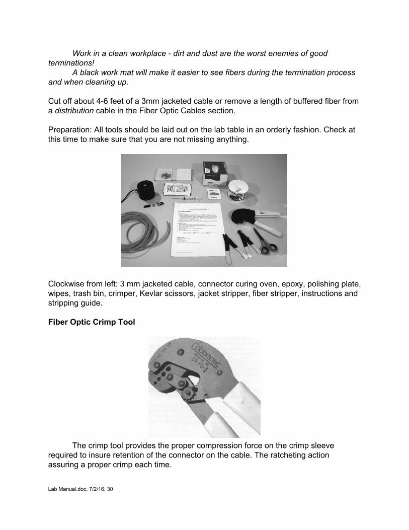
A black work mat will make it easier to see fibers during the termination process and when cleaning up. Cut off about 46 feet of a 3mm jacketed cable or remove a length of buffered fiber from a distribution cable in the Fiber Optic Cables section. Preparation: All tools should be laid out on the lab table in an orderly fashion. Check at this time to make sure that you are not missing anything.
Clockwise from left: 3 mm jacketed cable, connector curing oven, epoxy, polishing plate, wipes, trash bin, crimper, Kevlar scissors, jacket stripper, fiber stripper, instructions and stripping guide. Fiber Optic Crimp Tool
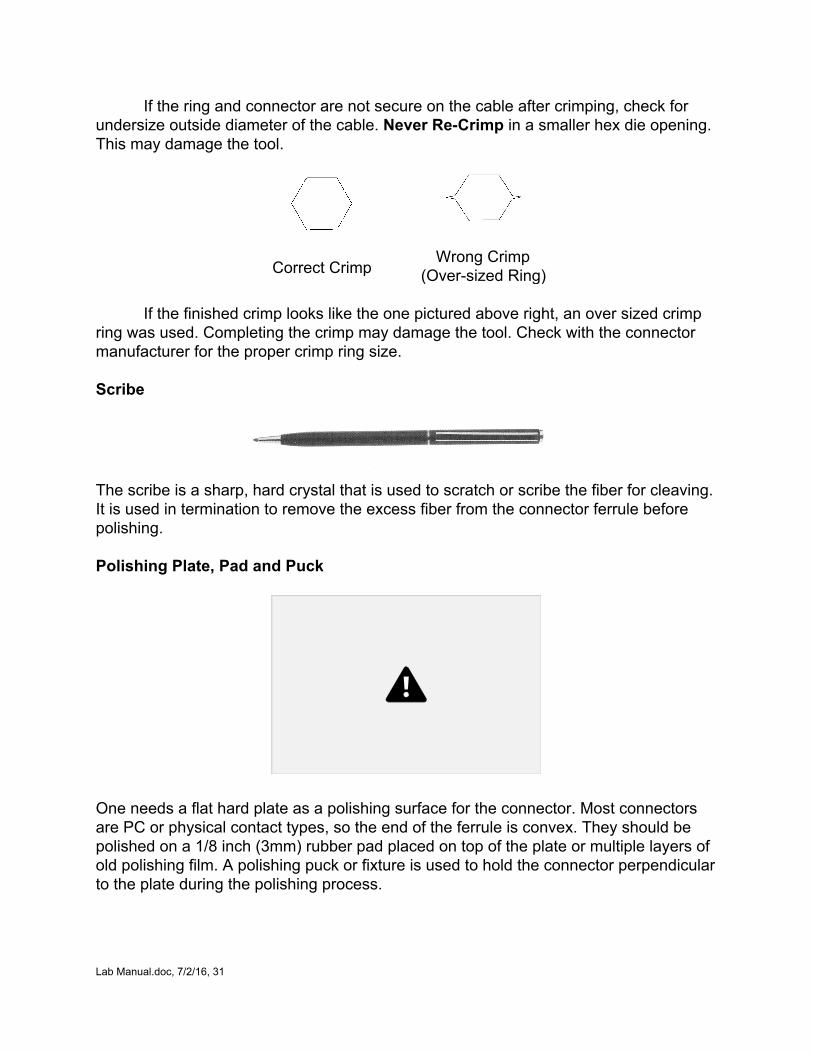
The crimp tool provides the proper compression force on the crimp sleeve
required to insure retention of the connector on the cable. The ratcheting action assuring a proper crimp each time.
Lab Manual.doc, 7/2/16, 30
If the ring and connector are not secure on the cable after crimping, check for undersize outside diameter of the cable. Never ReCrimp in a smaller hex die opening. This may damage the tool.
Correct Crimp
Wrong Crimp (Oversized Ring)
If the finished crimp looks like the one pictured above right, an over sized crimp
ring was used. Completing the crimp may damage the tool. Check with the connector manufacturer for the proper crimp ring size. Scribe
The scribe is a sharp, hard crystal that is used to scratch or scribe the fiber for cleaving. It is used in termination to remove the excess fiber from the connector ferrule before polishing. Polishing Plate, Pad and Puck
One needs a flat hard plate as a polishing surface for the connector. Most connectors are PC or physical contact types, so the end of the ferrule is convex. They should be polished on a 1/8 inch (3mm) rubber pad placed on top of the plate or multiple layers of old polishing film. A polishing puck or fixture is used to hold the connector perpendicular to the plate during the polishing process.
Lab Manual.doc, 7/2/16, 31
Applying Adhesives Epoxy is normally supplied in a “bipax” of epoxy and hardener. When ready to
use, mix by removing the center divider and working the two liquids inside the bipax with your fingers or on a hard surface. When fully mixed, cut one corner to create a small (3 mm, 1/8”) opening. Attach a square tip needle to the syringe and remove the plunger from the syringe. Carefully squeeze the adhesive into the syringe. Just start the plunger into the syringe, then hold needle up long enough to let the epoxy run down to the bottom, then squeeze the air out of the syringe. You now have about 30 minutes of working time to use the epoxy, long enough to share among all students in a class, so the instructor can be responsible for the adhesive.
The epoxy is applied by injecting a small amount into the connector until a bead
appears on the end of the connector, then the needle is pulled back slightly and more epoxy injected into the body of the connector.
Anaerobic adhesives do not require mixing. The recommended adhesive, Loctite 648, comes in a dropper bottle that can be simply wiped along a fiber that has been stripped and cleaned, and then the fiber is inserted in the connector.
HotMelt connectors already have adhesive – a hot melt adhesive – in the connector. The connectors are placed in an oven to melt the adhesive to allow inserting the fiber, then allowed to cool to set the adhesive.
Lab Manual.doc, 7/2/16, 32

I. Cable Preparation 3mm jacketed cable
1. Open the connector package in front of you and take out the parts. If the area is very dusty do not let the connector fall into the dust as this may clog the fiber hole. Also the connector should have a dust cap on the ferrule. Do not take it off until you are ready to install the connector. 2. On each cable end place a strain relief boot with the small side first.
3. Next place the crimp sleeve on the cable. It will be used to clamp on the Kevlar strength member of the cable and hold the strain relief boot to the connector after assembly. Your assembly should look as below.
4. Use the jacket strip tool to strip back the jacket of the cable exposing the needed length of buffered fiber, about 2 inches. This also exposes the Kevlar strength member of the cable. Use the #4 flat on the Miller stripper for 3mm jacket cable.
5. Using the scissors made to cut Kevlar provided in the Toolbox, cut back the Kevlar strength members,(leaving about 3/8 inch). NOTE: Connector manufacturers will specify the exact dimensions needed for stripping cable for their connectors. Ensure you have the proper information before trying to terminate that connector.
Lab Manual.doc, 7/2/16, 33
II. Fiber Preparation
Wear Safety Glasses for this exercise!! This part will take a bit of practice but as in all things just go step by step. We will proceed to connectorize one fiber at a time 1. Take your buffer strip tool and strip off from .75" to 1.0 inch of buffer material from
the fiber. Be careful that there is no debris in the tool jaws as it will cause the fiber to break. Some buffer materials adhere to the glass fiber tighter than others. It is advised that you take off short strips of about 1/8” to 1/4” at a time. Do not clamp squarely down on the fiber. This will bend and kink the fiber. Hold the tool at a steady angle to the fiber and pull buffer slowly and steadily down the fiber. (You may want to practice this step 56 times before mixing the epoxy)
Stripping Guide for 3 piece connectors with separate crimp ring:
Stripping Guide for 2 piece connectors with integral crimp ring:
2. There may be some debris left on the fiber after stripping. Take a clean lintfree wipe
dabbed with a little alcohol and wipe the fiber clean. Note: Do not use rubbing alcohol as it is mostly water and may prevent adhesive setting or affect its cured strength and reliability. Use 99% lab grade isopropyl alcohol ONLY.
Lab Manual.doc, 7/2/16, 34
III. Epoxy Preparation 1. Take the package of epoxy and remove the two part mix from the package. You will notice that there are two parts with a divider. Remove the divider. Mix the two halves together. If you do not have a tool designed specifically for mixing, such as a roller, the divider may be used. It is extremely important that you completely mix both halves together or the adhesive will not cure 100%. 2. Having mixed the epoxy completely take the empty syringe with needle attached and pull out the plunger. Be careful not to let the plunger roll in any dust. 3. Clip off one corner of the mixed epoxy pack and pour the mixture into the syringe. When the syringe is full place the plunger back in the syringe. 4. NOTE! Only place the plunger back in the syringe a very little bit as it will be full of air. Hold the syringe up side down and let the epoxy run down to the back of the syringe. When the epoxy runs down all the way you can push the plunger all the way forward removing the air. NOTE! your epoxy has a working time of 20 to 30 minutes. Other adhesives: Anaerobic adhesives are quicksetting one or twopart adhesives that do not require a heat cure. Anaerobic adhesives do not require mixing. The recommended adhesive, Loctite 648, comes in a dropper bottle that can be simply wiped along a fiber that has been stripped and cleaned, and then the fiber is inserted in the connector. 3M Hotmelt: 3M offers a heat setting adhesive that you heat the connector up to soften the adhesive, insert the stripped fiber and let it cool before polishing. Information and videos are available from 3M. Note that HotMelt connectors use a much hotter oven than heatcured epoxy. An epoxy oven will not soften the adhesive in HotMelt Connectors and a HotMelt oven will overheat and ruin epoxy!
Lab Manual.doc, 7/2/16, 35
IV. Attaching the Connector Wear Safety Glasses for this exercise!! 1. Remove the dust cap on the connector ferrule. 2. From the back of the connector body inject the connector with the epoxy. Make sure that the needle of the syringe is inside the connector body as far as it will go. Use light pressure on the plunger as you inject the epoxy until you see a small bead of the adhesive emerge from the ferrule tip. This bead will help hold the fiber during the cleaving process and ensure the proper cleave. Remove the syringe from the connector half way and continue to fill the connector until epoxy appears from the end of the connector. Remove the syringe from the connector and pull back on the plunger to prevent any adhesive from coming out of the needle. 3. Insert the stripped fiber through the back of the body of the connector towards the ferrule. Use a twisting motion on the connector to aid the glass fiber in finding the hole in the ferrule. Push the fiber in as far as it will go. 4. Move the crimp sleeve up over the back of the connector body, capturing the Kevlar, and crimp it to the body using the recommended crimp tool. 5 Place the strain relief boot over the back body of the connector. 6. Place the special protective sleeve provided over the ferrule of the connector, making sure not to break off the fiber and set it aside for overnight curing. This is to protect the fiber from breaking while you handle it before polishing and while curing. After you have successfully attached a connector to one end of the cable, do the same for the other end. If you have taken longer than 20 minutes, the epoxy will have hardened too much for use. You should wait until you polish your connector and then terminate the other end in another session to make a patchcord which you can test. Leave the cable assembly in a safe place to cure overnight or cure for the recommended curing time in an oven!
Lab Manual.doc, 7/2/16, 36
V. Cleaving After oven or overnight curing: Wear Safety Glasses for this exercise!! 1. Take your scribe tool and scribe the glass using light pressure so as not to break off the glass fiber from each connector. 2 or 3 scratches is enough. 2. Remove the glass by pulling both up and away as in figure 9.
3. You are now ready to polish the connector ferrule. VI. Polishing for Multimode Connectors
Polishing fiber optic connectors in the field is to some extent an art form. So it takes a “few tricks of the trade” so to speak to make it a clean and easy process. The operative word here is clean. This is the most important factor. Note: Singlemode technology is used in a lot of data rated applications. In these situations concerns over insertion loss are minimized and there is little concern over return loss. In these situations it is perfectly acceptable to treat a singlemode connector with a multimode polish. When concerns over return loss are present we change our polishing technique to accommodate it. Multimode polishing:
Lay your tools in front of you in an orderly fashion. You should have the glass plate, lapping films, polishing tool, and lintfree wipes. 1. Lay the 3 micron (yellow) and 0.3 (white) micron on the glass plate. Note that some films are adhesive backed. Make a double layer of these to create a softer surface. 2. Take the 15 micron (pink) film and one of the connectors to be polished. Hold the connector upright and the film with the grit facing down. With very light pressure polish the face of the connector so as only to take down the glass burr that remains from the scribe step.
Lab Manual.doc, 7/2/16, 37
3. Now observe the adhesive bead. Polish this down until it is a thin layer but not completely gone. Note: When you are doing an epoxyless connector with a stainless ferrule, polish the fiber down to the metal tip. 4. Place your connector in the polishing puck. Lay it down gently on the 3 micron lapping film, one side first. Do not slam it down hard as you could shatter the fiber. Using a figure 8 motion polish the connector until the adhesive bead is gone. If you are polishing a ceramic connector you will notice that the connector gets slippery on the plate. Stop polishing instantly. Now go to the 0.3 micron film With the same motion, go only one or two figure 8's. Your connector is done. Note: With a ceramic connector, you should use almost no pressure at all on the connector as you polish. With a stainless connector you will want a moderate amount of pressure of about two to three pounds. 5. Remove the connector from the polishing puck and wipe off the sides of the ferrule and the face of the ferrule to remove any dust and debris.
Lab Manual.doc, 7/2/16, 38
VII. Testing the Patchcord
After you have terminated both ends of a cable, you can test it to see how good your connectors are. Follow the procedure you learned in the Testing handson session and fill in the worksheet.
A. Continuity Test Using the Visible fiber tracer, test your cable to make sure it is continuous. Note
your observations on the worksheet.
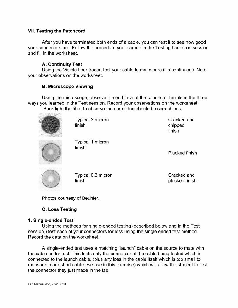
B. Microscope Viewing
Using the microscope, observe the end face of the connector ferrule in the three ways you learned in the Test session. Record your observations on the worksheet.
Back light the fiber to observe the core it too should be scratchless.
Typical 3 micron finish Typical 1 micron finish Typical 0.3 micron finish
Cracked and chipped finish Plucked finish Cracked and plucked finish.
Photos courtesy of Beuhler.
C. Loss Testing 1. Singleended Test
Using the methods for singleended testing (described below and in the Test session,) test each of your connectors for loss using the single ended test method. Record the data on the worksheet.
A singleended test uses a matching “launch” cable on the source to mate with the cable under test. This tests only the connector of the cable being tested which is connected to the launch cable, (plus any loss in the cable itself which is too small to measure in our short cables we use in this exercise) which will allow the student to test the connector they just made in the lab. Lab Manual.doc, 7/2/16, 39
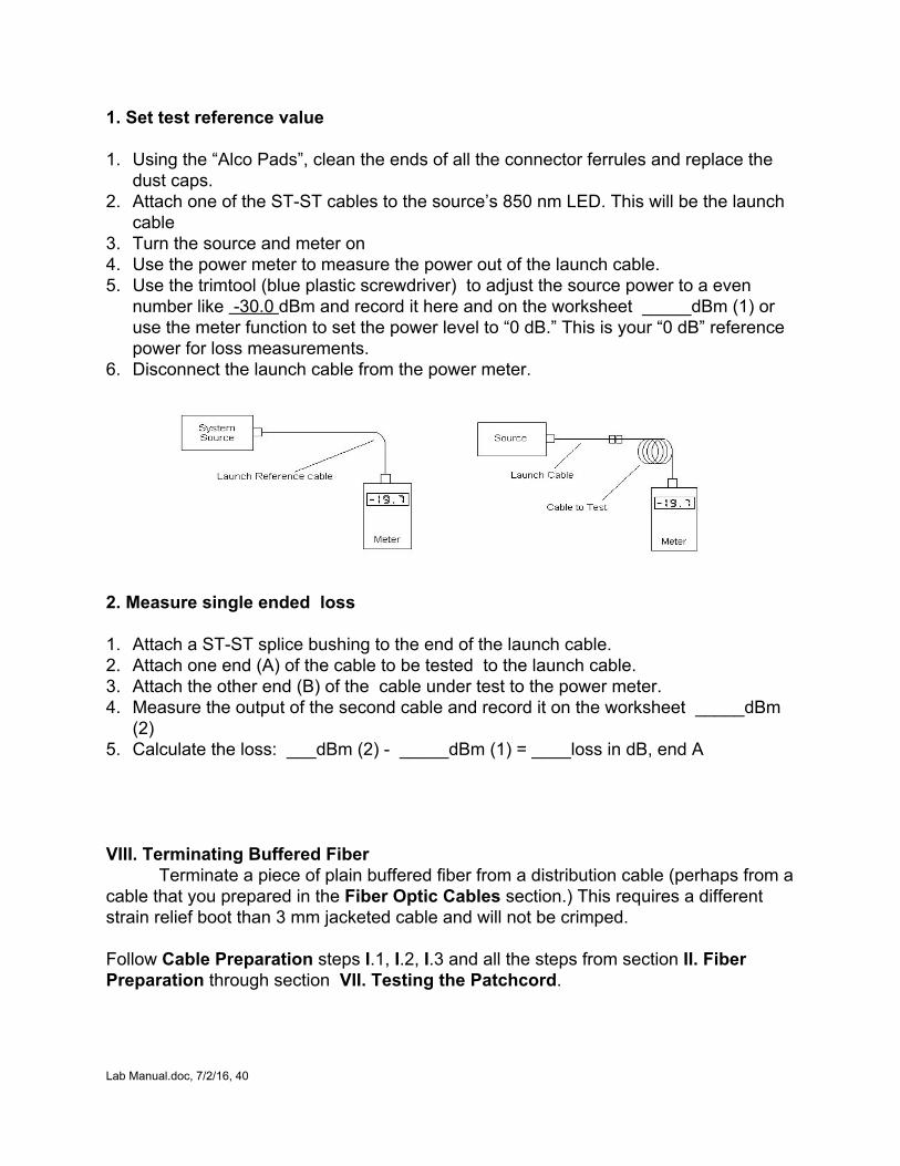
1. Set test reference value 1. Using the “Alco Pads”, clean the ends of all the connector ferrules and replace the
dust caps. 2. Attach one of the STST cables to the source’s 850 nm LED. This will be the launch
cable 3. Turn the source and meter on 4. Use the power meter to measure the power out of the launch cable. 5. Use the trimtool (blue plastic screwdriver) to adjust the source power to a even
number like 30.0 dBm and record it here and on the worksheet _____dBm (1) or use the meter function to set the power level to “0 dB.” This is your “0 dB” reference power for loss measurements.
6. Disconnect the launch cable from the power meter.
2. Measure single ended loss 1. Attach a STST splice bushing to the end of the launch cable. 2. Attach one end (A) of the cable to be tested to the launch cable. 3. Attach the other end (B) of the cable under test to the power meter. 4. Measure the output of the second cable and record it on the worksheet _____dBm
(2) 5. Calculate the loss: ___dBm (2) _____dBm (1) = ____loss in dB, end A
VIII. Terminating Buffered Fiber Terminate a piece of plain buffered fiber from a distribution cable (perhaps from a
cable that you prepared in the Fiber Optic Cables section.) This requires a different strain relief boot than 3 mm jacketed cable and will not be crimped. Follow Cable Preparation steps I.1, I.2, I.3 and all the steps from section II. Fiber Preparation through section VII. Testing the Patchcord.
Lab Manual.doc, 7/2/16, 40
Fiber Optic Cable Termination
Name:________________________________ What are the most common methods of fiber optic connector termination used in the field? 1._____________________ 2.________________ 3. ________________ 4.____________________ What are the worst enemies of terminations ? ______________________________________________________________ How do you know when you have injected epoxy into the connector properly? ___________________________________________________________ What do we call the polishing motion we use on the lapping films? ____________________________________________________________
VIII. Testing Once you have terminated your cable, test it and record the data on this worksheet. Make extra copies for each patchcord if you need them. Cable No.___________ A. Continuity Test 1. Were you able to see light through your cable?___________________________
_____________________________________________________________
2. Was there any difference in intensity when direction was
reversed?___________________________________________________________
_____________________________________________________________
Lab Manual.doc, 7/2/16, 41
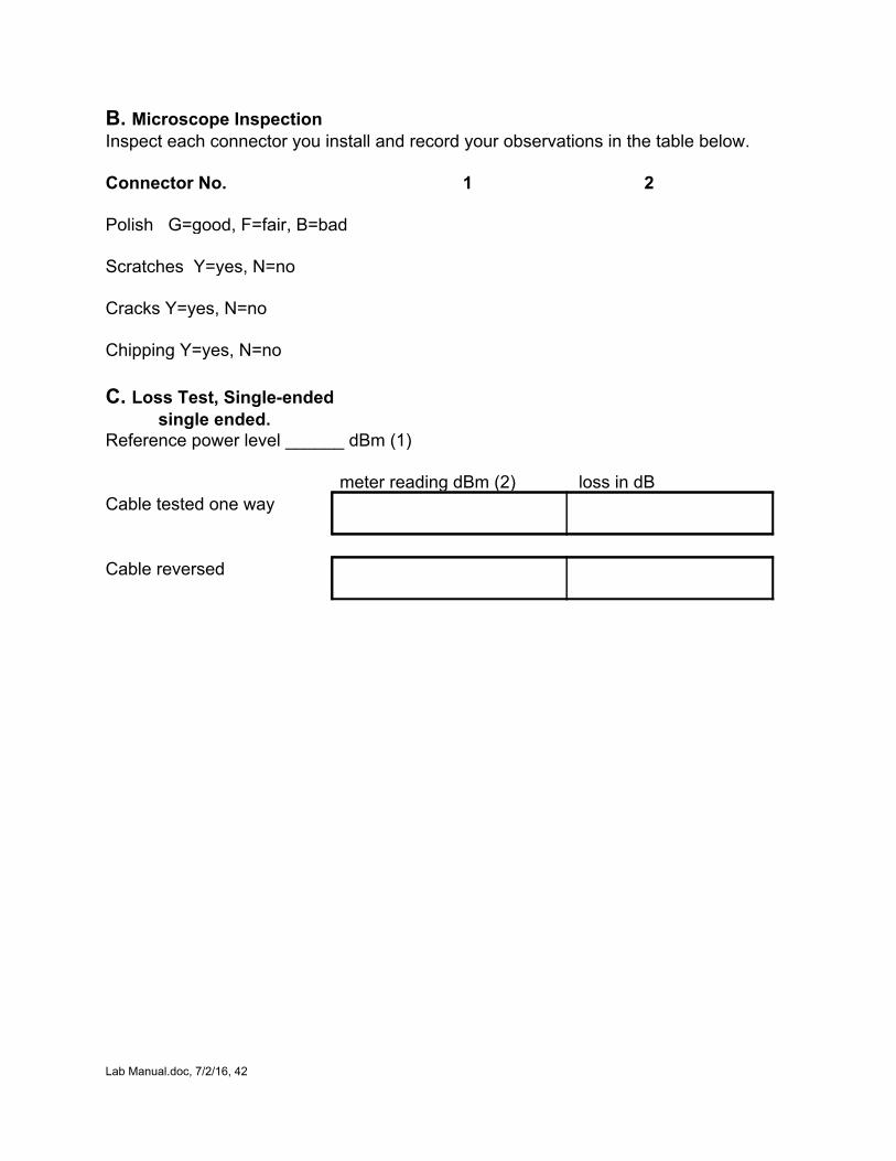
B. Microscope Inspection Inspect each connector you install and record your observations in the table below. Connector No. 1 2 Polish G=good, F=fair, B=bad Scratches Y=yes, N=no Cracks Y=yes, N=no Chipping Y=yes, N=no
C. Loss Test, Singleended
single ended. Reference power level ______ dBm (1) meter reading dBm (2) loss in dB Cable tested one way
Cable reversed
Lab Manual.doc, 7/2/16, 42
Splicing
What Students Learn: How a mechanical and/or fusion splicing works How to prepare fibers for splicing Making mechanical and/or fusion splices How to optimize the mechanical splice Exercises: I. Preparing the Cable II. Stripping and Cleaving III. Inspection IV. Inserting the Fiber into the Splice
A. Finishing the Splice B. Testing the Splice C. Optimizing the Splice
Visual Aids
The following visual aids show the processes described in these exercises. They may be shown to the students before the lab or just used as a reference by the instructor.
FOA PPT: Splicing, Slides # 107124 FOA Instructional Videos (Online or DVD): Mechanical Splicing FOA Online Reference Guide To Fiber Optics: Basics/Cables, Splicing VHO (mechanical, fusion and ribbon)
Safety: All students and instructors must wear safety glasses in this lab. Follow all safety rules for working with fiber. Safely dispose of all fiber scraps and cables after use. Materials Needed: Safety Glasses ST patch cord Fiber Optic stripper Microscope with bare fiber stage Test equipment: VFL and OLTS Scribe Miller Jacket stripper Trash bin Mechanical Splice consumables: 3 Ultrasplices: Alcopads or lintfree pads and 99% isopropyl alcohol Power meter and Source Bare fiber holder Cleave fixture Lab Manual.doc, 7/2/16, 43
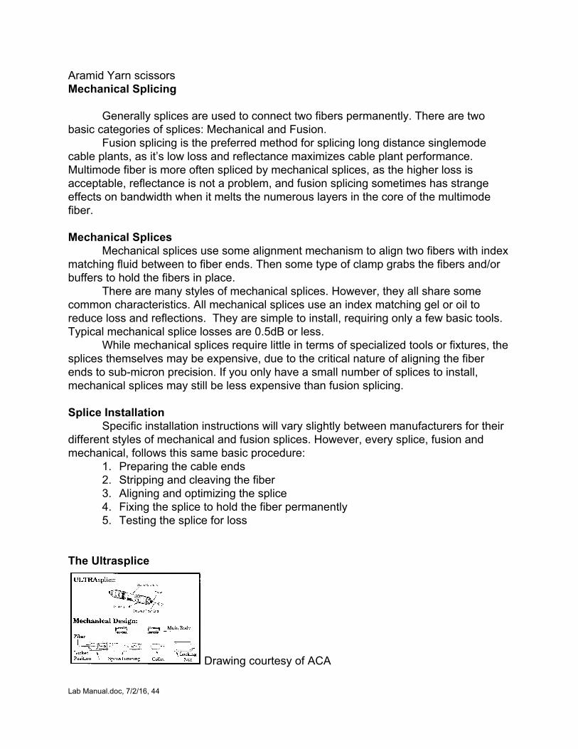
Aramid Yarn scissors Mechanical Splicing
Generally splices are used to connect two fibers permanently. There are two basic categories of splices: Mechanical and Fusion.
Fusion splicing is the preferred method for splicing long distance singlemode cable plants, as it’s low loss and reflectance maximizes cable plant performance. Multimode fiber is more often spliced by mechanical splices, as the higher loss is acceptable, reflectance is not a problem, and fusion splicing sometimes has strange effects on bandwidth when it melts the numerous layers in the core of the multimode fiber. Mechanical Splices
Mechanical splices use some alignment mechanism to align two fibers with index matching fluid between to fiber ends. Then some type of clamp grabs the fibers and/or buffers to hold the fibers in place.
There are many styles of mechanical splices. However, they all share some common characteristics. All mechanical splices use an index matching gel or oil to reduce loss and reflections. They are simple to install, requiring only a few basic tools. Typical mechanical splice losses are 0.5dB or less.
While mechanical splices require little in terms of specialized tools or fixtures, the splices themselves may be expensive, due to the critical nature of aligning the fiber ends to submicron precision. If you only have a small number of splices to install, mechanical splices may still be less expensive than fusion splicing.
Splice Installation
Specific installation instructions will vary slightly between manufacturers for their different styles of mechanical and fusion splices. However, every splice, fusion and mechanical, follows this same basic procedure:
1. Preparing the cable ends 2. Stripping and cleaving the fiber 3. Aligning and optimizing the splice 4. Fixing the splice to hold the fiber permanently 5. Testing the splice for loss
The Ultrasplice
Drawing courtesy of ACA Lab Manual.doc, 7/2/16, 44
I. Preparing the Cable Wear Safety Glasses for this exercise!! Note: If cutting a patchcord and splicing it, record the loss reading of the cable before beginning. 1. Cut the cable in half. 2. Remove approximately 6 inches of the jacket from each end leaving the buffered
fiber. (See the cable or termination exercise for procedures) II. Stripping and Cleaving
Wear Safety Glasses for this exercise!!
Do not strip both fibers to be spliced at once. Strip one side, cleave it, insert it into the splice, then strip the other fiber. This is safer and avoids breakage. 1. With the fiber stripper, strip away the buffer coating exposing approximately 11/2 to
2 inches of the glass fiber. 2. Lay the fiber on the cleave fixture with the buffer end 7 mm (0.3 in.) from the center
(pivot point) of the fixture, holding it tightly with two fingers as shown in the cleaving instructions in the Toolbox Manual.
3. Scribe the fiber with the scribing tool at a point 79 mm from the end of the buffer. 4. Push down both ends of the fixture until it touches the tabletop. 5. The fiber should cleave at the scribe point. (This process takes some practice to get
the right “feel” for the scribe. You may want to practice with other fiber supplied in the Termination consumables kit before trying it on your patchcord.)
Lab Manual.doc, 7/2/16, 45
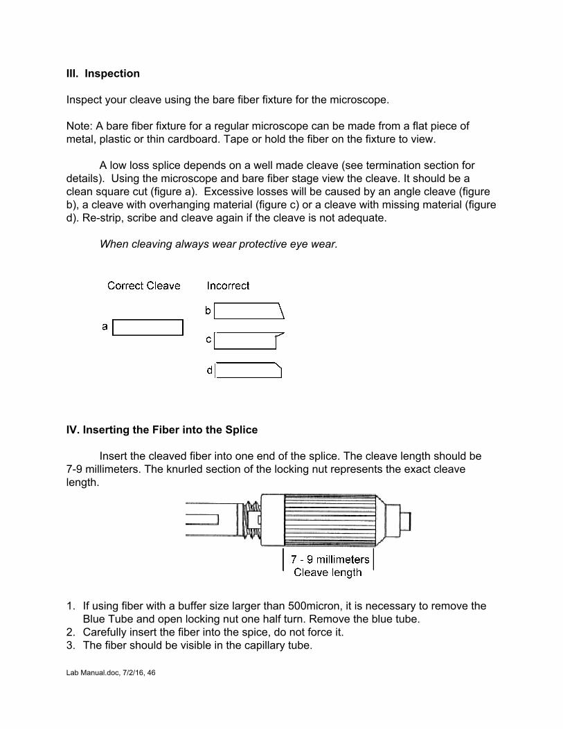
III. Inspection Inspect your cleave using the bare fiber fixture for the microscope. Note: A bare fiber fixture for a regular microscope can be made from a flat piece of metal, plastic or thin cardboard. Tape or hold the fiber on the fixture to view.
A low loss splice depends on a well made cleave (see termination section for details). Using the microscope and bare fiber stage view the cleave. It should be a clean square cut (figure a). Excessive losses will be caused by an angle cleave (figure b), a cleave with overhanging material (figure c) or a cleave with missing material (figure d). Restrip, scribe and cleave again if the cleave is not adequate.
When cleaving always wear protective eye wear.
IV. Inserting the Fiber into the Splice
Insert the cleaved fiber into one end of the splice. The cleave length should be 79 millimeters. The knurled section of the locking nut represents the exact cleave length.
1. If using fiber with a buffer size larger than 500micron, it is necessary to remove the
Blue Tube and open locking nut one half turn. Remove the blue tube. 2. Carefully insert the fiber into the spice, do not force it. 3. The fiber should be visible in the capillary tube.
Lab Manual.doc, 7/2/16, 46
4. Center the fiber in the capillary tube. 5. Lock the fiber in the splice by tightening the locking nut with a clockwise rotation.
(The fiber is held in place by the collet. The collet acts like a drill chuck. When the locking nut is tightened down on it the collet grips the buffer of the fiber. The locking nut is designed to strip if too much force is used.)
A. Finishing the Splice 1. Cleave the other fiber in the same manner as before. 2. Insert the second fiber and gently butt up against the first fiber. Do not force the
fibers together, this will cause them to break. 3. Secure in place with the locking nut.
B. Testing the splice
1. Use the meter, source and one of the preterminated cables to test the cable which
now has a splice in it. 2. Record the loss. 3. Calculate the additional loss of the splice. C. Optimizing the Splice
You can sometimes improve the loss of a mechanical splice by gently withdrawing one of the fibers a slight amount, rotating it slightly and reinserting it. Try this with your splice. 1. Attach the spliced cable to the meter and source 2. Record meter reading 3. Unlock one splice locking nut 4. Pull that fiber out by 1mm (about 1/16 inch) 5. Rotate the fiber 30 degrees and gently reinsert 6. Note the power meter reading. Did the loss increase or decrease? 7. Try the process again and note the results on the worksheets.
Lab Manual.doc, 7/2/16, 47
Fusion Splicing Lab What Students Learn: How to prepare fibers for fusion splicing The process of fusion splicing How to protect fusion splices Exercises: I. Preparing the Cable II. Stripping fibers III. Cleaving IV. Fusion splicing V. Attaching splice protector Visual Aids
The following visual aids show the processes described in these exercises. They may be shown to the students before the lab or just used as a reference by the instructor.
FOA PPT: Splicing, Single fiber: Slides # 3779, Ribbon: Slides # 80105 FOA Instructional Videos (Online or DVD): Mechanical Splicing FOA Online Reference Guide To Fiber Optics: Basics/Cables, Splicing VHOs (mechanical, fusion and ribbon)
Safety: All students and instructors must wear safety glasses in this lab. Follow all safety rules for working with fiber. Safely dispose of all fiber scraps and cables after use.
For the trained fiber optic technician who already understands the basics of fiber optics and installation practices, this advanced lab is designed to introduce the student to the theory and practice of fusion splicing fiber optics. The student will learn what a fusion splice is, what equipment is needed, how it is done and will practice making single fiber and ribbon fiber splices, placing splices into a splice tray, including testing each splice as made, mirroring actual field installation practices. For students in a basic fiber course, a shorter introduction to splicing can be done by having each student strip fibers and complete one fusion splice, then covering splice trays and closures as a class.
Teaching fusion splicing requires training material specific to the splice machine chosen, so if you intend to teach fusion, get the manufacturer to of the chosen machine to assist you and provide training materials if available. The FOA PPT on Splicing and the Online VHOs cover these processes step by step in great detail using typical splicers.
It is assumed that the instructor teaching a fusion splicing lab will be familiar with the equipment and its use and has available training aids like the FOA PPT on splicing and/or Internet access and can project the VHOs. An advanced lab should have access
Lab Manual.doc, 7/2/16, 48
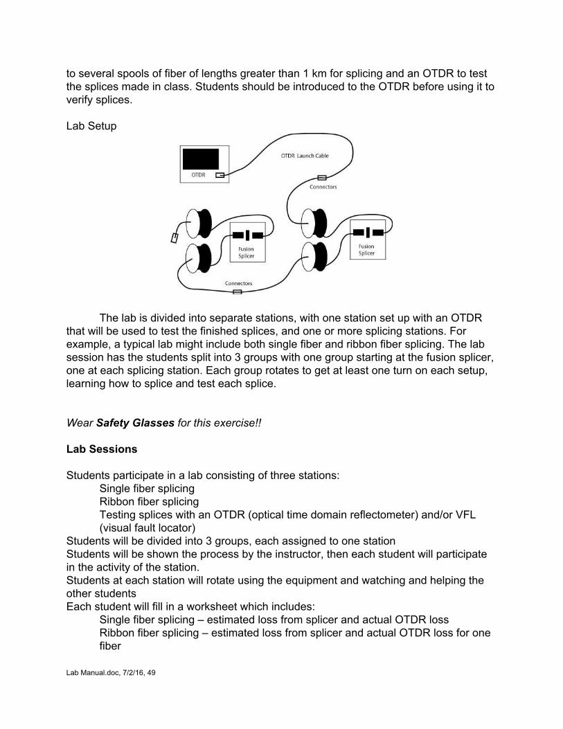
to several spools of fiber of lengths greater than 1 km for splicing and an OTDR to test the splices made in class. Students should be introduced to the OTDR before using it to verify splices. Lab Setup
The lab is divided into separate stations, with one station set up with an OTDR that will be used to test the finished splices, and one or more splicing stations. For example, a typical lab might include both single fiber and ribbon fiber splicing. The lab session has the students split into 3 groups with one group starting at the fusion splicer, one at each splicing station. Each group rotates to get at least one turn on each setup, learning how to splice and test each splice. Wear Safety Glasses for this exercise!! Lab Sessions Students participate in a lab consisting of three stations:
Single fiber splicing Ribbon fiber splicing Testing splices with an OTDR (optical time domain reflectometer) and/or VFL (visual fault locator)
Students will be divided into 3 groups, each assigned to one station Students will be shown the process by the instructor, then each student will participate in the activity of the station. Students at each station will rotate using the equipment and watching and helping the other students Each student will fill in a worksheet which includes:
Single fiber splicing – estimated loss from splicer and actual OTDR loss Ribbon fiber splicing – estimated loss from splicer and actual OTDR loss for one fiber
Lab Manual.doc, 7/2/16, 49
Testing: OTDR data or trace for one completed link (4 spools and 2 splices) Students should rotate through each station Testing Fusion Splices
Every fusion splicer makes an estimate of the loss of the splice using calculations based on the alignment method. This estimate can be inaccurate on some splices. The lab setup shown has the advantage that each splice can be tested with an OTDR and the loss of the splice verified. If possible, for one or more splices, test in each direction with the OTDR and note differences. If a directional difference is noted, measure the attenuation coefficient of each fiber and see if the relationship of fiber attenuation coefficient and loss differences at the splice are as predicted.
Lab Manual.doc, 7/2/16, 50
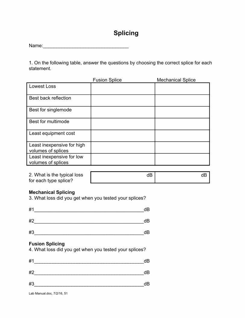
Splicing Name:________________________________ 1. On the following table, answer the questions by choosing the correct splice for each statement. Fusion Splice Mechanical Splice Lowest Loss
Best back reflection
Best for singlemode
Best for multimode
Least equipment cost
Least inexpensive for high volumes of splices
Least inexpensive for low volumes of splices
2. What is the typical loss for each type splice?
dB dB
Mechanical Splicing 3. What loss did you get when you tested your splices? #1_________________________________________dB #2_________________________________________dB #3_________________________________________dB Fusion Splicing 4. What loss did you get when you tested your splices? #1_________________________________________dB #2_________________________________________dB #3_________________________________________dB
Lab Manual.doc, 7/2/16, 51
D. OTDR Testing What Students Learn: The appropriate applications of an OTDR The correct way to set up the OTDR How to analyze traces on the OTDR OTDR problems and limitations
OTDRs test optical fibers and fiber optic cable systems using an indirect method that depends on the backscatter of light in the fiber. While all international standards require OLTS (light source and power meter) testing of installed cable plants, OTDRs are routinely used to check splices and find sources of stress loss that can affect long term reliability. OTDRs are also used for fault location and troubleshooting.
While OTDRs are primarily used for outside plant cabling, manufacturers have been promoting their use in premises and campus networks. The technical calls taken by the FOA indicates that the use of OTDRs in these types of short cable plants has been a major source of confusion, particularly for installers who are new to OTDRs and have been told to connect it to the network and hit the “autotest” button.
Thus, the goal of the classroom training and this lab is to show the students the proper applications in which to use of the instrument as well as how to use it properly. This may be done in two ways, using the OTDR Simulator available from the FOA or an OTDR and simulated cable plant. We will offer both ways. 1. Using The OTDR Simulator
The FOA Testing and OTDR PPTs have details on how the OTDR works. The instructions for the OTDR simulator are in a manual and on a PPT presentation. The simulator can be loaded on a Windows XP PC using the installation instructions. There are three file folders containing about 80 traces that should be loaded on the PC also. One contains multiple traces of the same cable plant taken with different OTDR setups, one contains field traces and one has FTTX traces through a PONtype coupler (with only 2 ports to simplify understanding how couplers are seen on OTDRs.)
The instructor needs to practice with the OTDR simulator to understand its use. The PPT on how to use the simulator is good training.
Lab Manual.doc, 7/2/16, 52
Setting up the OTDR The secret to getting good traces in the OTDR is to set the test parameters
properly. In the “Parameters” folder, there are 26 traces taken of one cable plant – about 5.2 km of multimode fiber in 4 segments with each trace using a different setup parameter. Thus, one can open traces from the folder that can be shown as comparisons on the display to allow the student to see the effects of the setup. Range
There are 6 range files. Range changes the scale on the display and the timing of the test pulses. Note that on the longer ranges, the 5.2 km cable plant has poor resolution and on the shortest one, the display is distorted since the OTDR does not have time to get the test pulse back before the next pulse is sent. Averaging
The OTDR sends out multiple test pulses and averages the result. Take a look at the traces at 1 and 1024 averages and note the difference in signal to noise in the trace. Try several others to see what is a good value for this cable plant. 0 Index of Refraction (n)
The Index of Refraction (n) is a measure of the speed of light in the fiber, so it is used to calibrate the distance to events. Compare the three traces taken at different values of n and see how the traces change.
Pulse Width
Wider pulse widths give the test pulse more energy so the OTDR can see a longer distance. But the trade off is resolution, not just in distance but in dB, as the comparison between these traces show.
Wavelength
OTDRs typically test at two wavelengths, 850 and 1300 nm for multimode, 1310 and 1550 for singlemode and sometimes 1620 nm for finding high stress loss areas in singlemode cable plants. Open the 850 and 1300 nm traces and compare them. Analyzing Fiber Traces
There are 50 traces to analyze, including 4 through couplers for seeing what happens in a PON system. Some of these are analyzed in the notes to the OTDR simulator but all are available for classroom or student analysis. See if you can find the one with the “perfect” gainer. 2. Using An OTDR In The Classroom
Lab Manual.doc, 7/2/16, 53
If the classroom has an OTDR for student training, it needs appropriate launch cables, sometimes called “pulse suppressor” cables and several long spools of fiber to allow the students to see how the OTDR analyzes fibers. These long spools can be joined by fusion splicing them together or by terminating them. Multimode can be terminated directly (using a breakout kit is the fibers are 250 micron buffered fibers) but singlemode fibers should have pigtails spliced onto the fibers.
OTDRs are sometimes used to test bare fibers using mechanical splices to connect to the fiber to be tested. The splices used in the mechanical splicing exercise can be used to splice a long pigtail (long enough to be a good launch cable) to a spool of fiber to test.
Exercises should include setting up the OTDR parameters and then analyzing traces. Additional exercises include using short fibers to show the limitations of the OTDR when testing short cables and, if the short cable is prepared with a cleaved or polished far end, to show ghosts and showing how the OTDR autotest function compares to a properly set up OTDR. If possible, use an OTDR that has provision to be connected to a projector to allow all
students to participate in the activities.
Lab Manual.doc, 7/2/16, 54
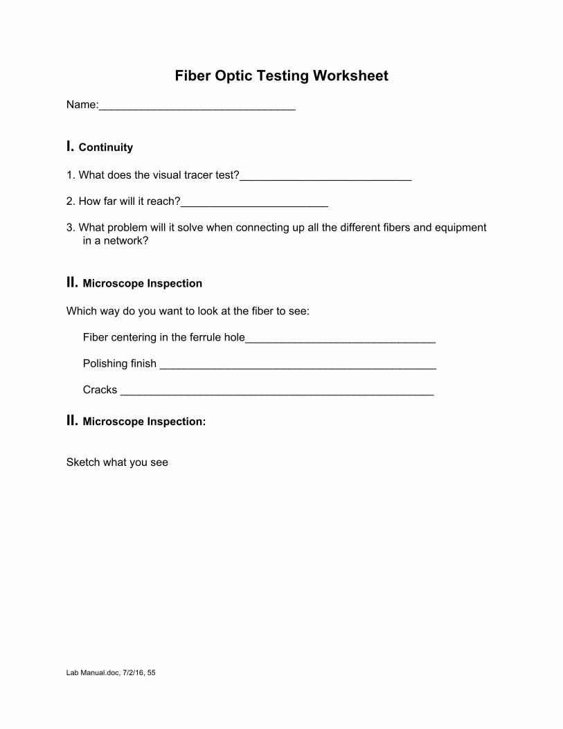
Fiber Optic Testing Worksheet Name:________________________________
I. Continuity 1. What does the visual tracer test?____________________________ 2. How far will it reach?________________________ 3. What problem will it solve when connecting up all the different fibers and equipment
in a network? II. Microscope Inspection Which way do you want to look at the fiber to see:
Fiber centering in the ferrule hole_______________________________
Polishing finish _____________________________________________
Cracks ___________________________________________________
II. Microscope Inspection: Sketch what you see
Lab Manual.doc, 7/2/16, 55

III. Measuring Optical Power: 1. Which optical measurment is absolute and which is relative?
Power ___Relative ___Absolute
Loss ___Relative ___Absolute
2. Which is the higher power?
0dBm or 30dBm ? 0dBm or +10dBm ?
3. Convert to 0dBm to Watts.
0dBm = ________
Lab Manual.doc, 7/2/16, 56
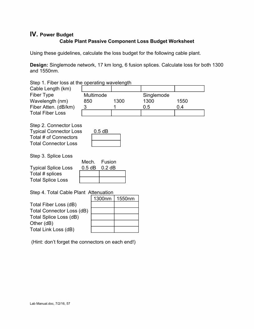
IV. Power Budget Cable Plant Passive Component Loss Budget Worksheet
Using these guidelines, calculate the loss budget for the following cable plant. Design: Singlemode network, 17 km long, 6 fusion splices. Calculate loss for both 1300 and 1550nm. Step 1. Fiber loss at the operating wavelength Cable Length (km) Fiber Type Multimode Singlemode Wavelength (nm) 850 1300 1300 1550 Fiber Atten. (dB/km) 3 1 0.5 0.4 Total Fiber Loss Step 2. Connector Loss Typical Connector Loss 0.5 dB Total # of Connectors Total Connector Loss Step 3. Splice Loss Mech. Fusion Typical Splice Loss 0.5 dB 0.2 dB Total # splices Total Splice Loss Step 4. Total Cable Plant Attenuation 1300nm 1550nm Total Fiber Loss (dB) Total Connector Loss (dB) Total Splice Loss (dB) Other (dB) Total Link Loss (dB) (Hint: don’t forget the connectors on each end!)
Lab Manual.doc, 7/2/16, 57
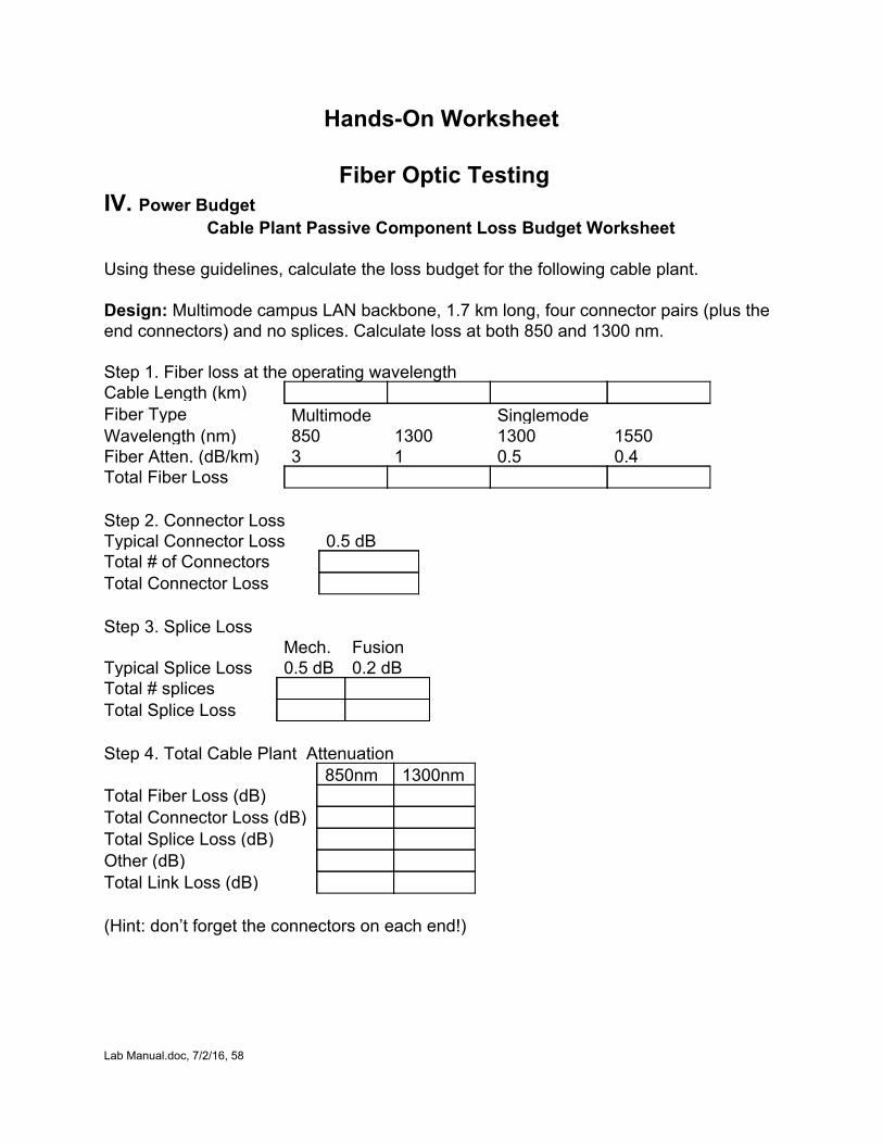
HandsOn Worksheet
Fiber Optic Testing IV. Power Budget
Cable Plant Passive Component Loss Budget Worksheet Using these guidelines, calculate the loss budget for the following cable plant. Design: Multimode campus LAN backbone, 1.7 km long, four connector pairs (plus the end connectors) and no splices. Calculate loss at both 850 and 1300 nm. Step 1. Fiber loss at the operating wavelength Cable Length (km) Fiber Type Multimode Singlemode Wavelength (nm) 850 1300 1300 1550 Fiber Atten. (dB/km) 3 1 0.5 0.4 Total Fiber Loss Step 2. Connector Loss Typical Connector Loss 0.5 dB Total # of Connectors Total Connector Loss Step 3. Splice Loss Mech. Fusion Typical Splice Loss 0.5 dB 0.2 dB Total # splices Total Splice Loss Step 4. Total Cable Plant Attenuation 850nm 1300nm Total Fiber Loss (dB) Total Connector Loss (dB) Total Splice Loss (dB) Other (dB) Total Link Loss (dB) (Hint: don’t forget the connectors on each end!)
Lab Manual.doc, 7/2/16, 58
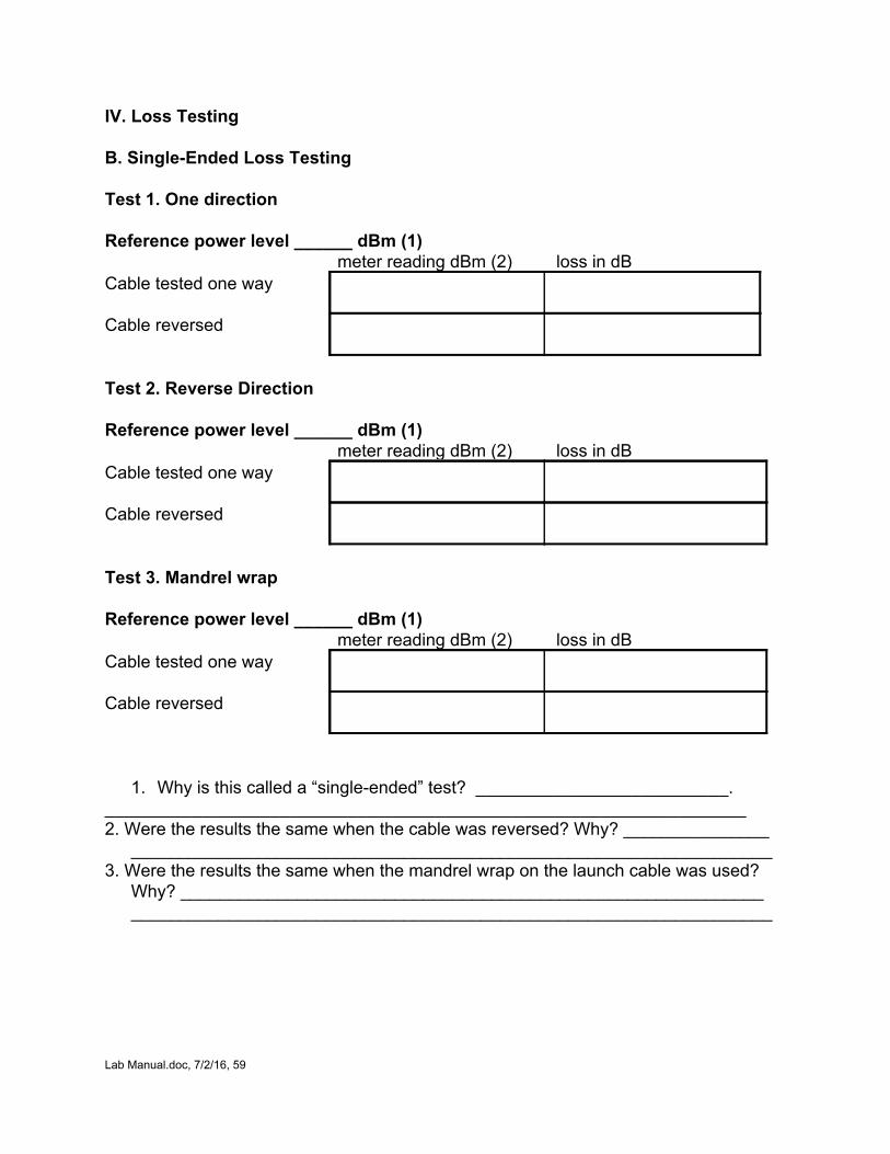
IV. Loss Testing B. SingleEnded Loss Testing Test 1. One direction Reference power level ______ dBm (1) meter reading dBm (2) loss in dB Cable tested one way
Cable reversed
Test 2. Reverse Direction Reference power level ______ dBm (1) meter reading dBm (2) loss in dB Cable tested one way
Cable reversed
Test 3. Mandrel wrap Reference power level ______ dBm (1) meter reading dBm (2) loss in dB Cable tested one way
Cable reversed
1. Why is this called a “singleended” test? __________________________. __________________________________________________________________ 2. Were the results the same when the cable was reversed? Why? _______________
__________________________________________________________________ 3. Were the results the same when the mandrel wrap on the launch cable was used?
Why? ____________________________________________________________ __________________________________________________________________
Lab Manual.doc, 7/2/16, 59
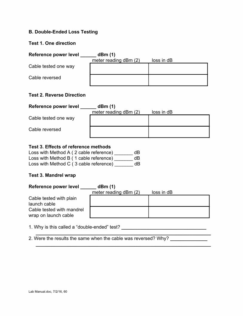
B. DoubleEnded Loss Testing Test 1. One direction Reference power level ______ dBm (1) meter reading dBm (2) loss in dB Cable tested one way
Cable reversed
Test 2. Reverse Direction Reference power level ______ dBm (1) meter reading dBm (2) loss in dB Cable tested one way
Cable reversed
Test 3. Effects of reference methods Loss with Method A ( 2 cable reference) _______ dB Loss with Method B ( 1 cable reference) _______ dB Loss with Method C ( 3 cable reference) _______ dB Test 3. Mandrel wrap Reference power level ______ dBm (1) meter reading dBm (2) loss in dB Cable tested with plain launch cable
Cable tested with mandrel wrap on launch cable
1. Why is this called a “doubleended” test? ________________________________
__________________________________________________________________ 2. Were the results the same when the cable was reversed? Why? ______________
__________________________________________________________________
Lab Manual.doc, 7/2/16, 60