Embed Size (px)
Citation preview
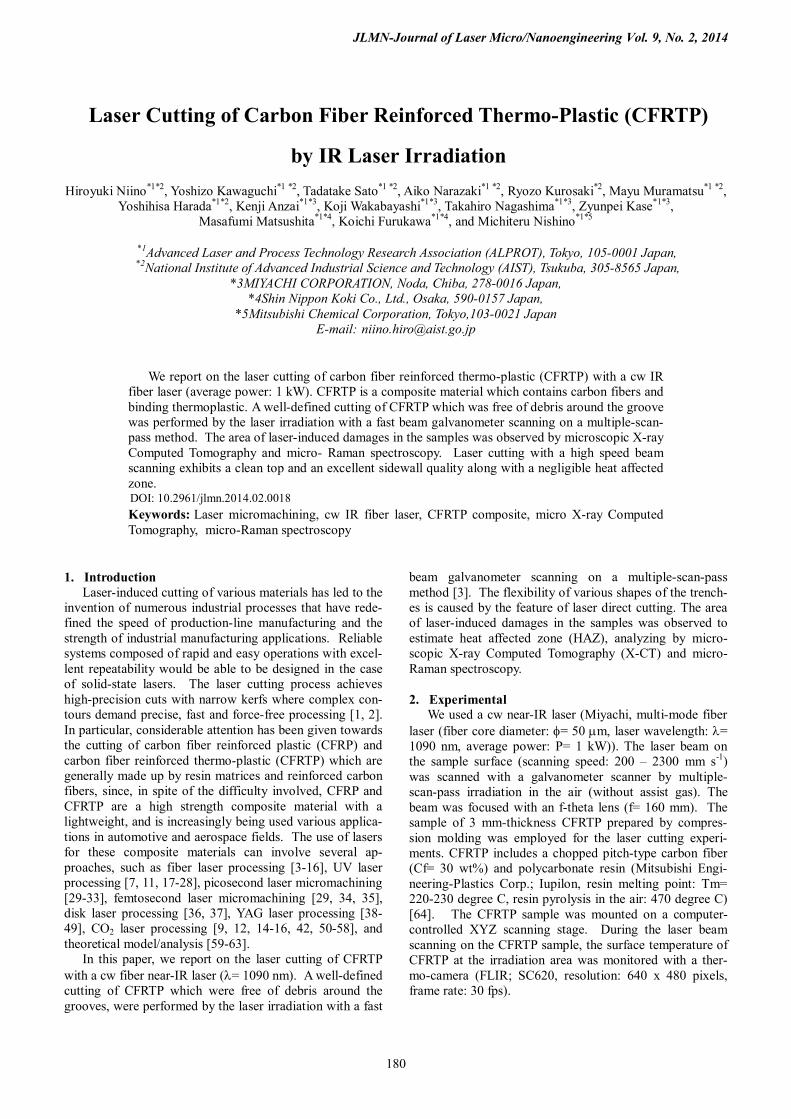
JLMN-Journal of Laser Micro/Nanoengineering Vol. 9, No. 2, 2014
180
Laser Cutting of Carbon Fiber Reinforced Thermo-Plastic (CFRTP)
by IR Laser Irradiation
Hiroyuki Niino*1*2, Yoshizo Kawaguchi*1 *2, Tadatake Sato*1 *2, Aiko Narazaki*1 *2, Ryozo Kurosaki*2, Mayu Muramatsu*1 *2, Yoshihisa Harada*1*2, Kenji Anzai*1*3, Koji Wakabayashi*1*3, Takahiro Nagashima*1*3, Zyunpei Kase*1*3,
Masafumi Matsushita*1*4, Koichi Furukawa*1*4, and Michiteru Nishino*1*5
*1Advanced Laser and Process Technology Research Association (ALPROT), Tokyo, 105-0001 Japan, *2National Institute of Advanced Industrial Science and Technology (AIST), Tsukuba, 305-8565 Japan,
*3MIYACHI CORPORATION, Noda, Chiba, 278-0016 Japan, *4Shin Nippon Koki Co., Ltd., Osaka, 590-0157 Japan,
*5Mitsubishi Chemical Corporation, Tokyo,103-0021 Japan E-mail: [email protected]
We report on the laser cutting of carbon fiber reinforced thermo-plastic (CFRTP) with a cw IR fiber laser (average power: 1 kW). CFRTP is a composite material which contains carbon fibers and binding thermoplastic. A well-defined cutting of CFRTP which was free of debris around the groove was performed by the laser irradiation with a fast beam galvanometer scanning on a multiple-scan-pass method. The area of laser-induced damages in the samples was observed by microscopic X-ray Computed Tomography and micro- Raman spectroscopy. Laser cutting with a high speed beam scanning exhibits a clean top and an excellent sidewall quality along with a negligible heat affected zone.
Keywords: Laser micromachining, cw IR fiber laser, CFRTP composite, micro X-ray Computed Tomography, micro-Raman spectroscopy
1. Introduction Laser-induced cutting of various materials has led to the
invention of numerous industrial processes that have rede-fined the speed of production-line manufacturing and the strength of industrial manufacturing applications. Reliable systems composed of rapid and easy operations with excel-lent repeatability would be able to be designed in the case of solid-state lasers. The laser cutting process achieves high-precision cuts with narrow kerfs where complex con-tours demand precise, fast and force-free processing [1, 2]. In particular, considerable attention has been given towards the cutting of carbon fiber reinforced plastic (CFRP) and carbon fiber reinforced thermo-plastic (CFRTP) which are generally made up by resin matrices and reinforced carbon fibers, since, in spite of the difficulty involved, CFRP and CFRTP are a high strength composite material with a lightweight, and is increasingly being used various applica-tions in automotive and aerospace fields. The use of lasers for these composite materials can involve several ap-proaches, such as fiber laser processing [3-16], UV laser processing [7, 11, 17-28], picosecond laser micromachining [29-33], femtosecond laser micromachining [29, 34, 35], disk laser processing [36, 37], YAG laser processing [38-49], CO2 laser processing [9, 12, 14-16, 42, 50-58], and theoretical model/analysis [59-63].
In this paper, we report on the laser cutting of CFRTP with a cw fiber near-IR laser (λ= 1090 nm). A well-defined cutting of CFRTP which were free of debris around the grooves, were performed by the laser irradiation with a fast
beam galvanometer scanning on a multiple-scan-pass method [3]. The flexibility of various shapes of the trench-es is caused by the feature of laser direct cutting. The area of laser-induced damages in the samples was observed to estimate heat affected zone (HAZ), analyzing by micro-scopic X-ray Computed Tomography (X-CT) and micro- Raman spectroscopy. 2. Experimental
We used a cw near-IR laser (Miyachi, multi-mode fiber laser (fiber core diameter: φ= 50 mm, laser wavelength: λ= 1090 nm, average power: P= 1 kW)). The laser beam on the sample surface (scanning speed: 200 – 2300 mm s-1) was scanned with a galvanometer scanner by multiple-scan-pass irradiation in the air (without assist gas). The beam was focused with an f-theta lens (f= 160 mm). The sample of 3 mm-thickness CFRTP prepared by compres-sion molding was employed for the laser cutting experi-ments. CFRTP includes a chopped pitch-type carbon fiber (Cf= 30 wt%) and polycarbonate resin (Mitsubishi Engi-neering-Plastics Corp.; Iupilon, resin melting point: Tm= 220-230 degree C, resin pyrolysis in the air: 470 degree C) [64]. The CFRTP sample was mounted on a computer-controlled XYZ scanning stage. During the laser beam scanning on the CFRTP sample, the surface temperature of CFRTP at the irradiation area was monitored with a ther-mo-camera (FLIR; SC620, resolution: 640 x 480 pixels, frame rate: 30 fps).
DOI: 10.2961/jlmn.2014.02.0018

JLMN-Journal of Laser Micro/Nanoengineering Vol. 9, No. 2, 2014
181
The internal damages of laser-cutting samples were ob-served with a micro X-ray Computed Tomography system (Yamato Science Co.; TDM1000H-Sμ/TDM1600H-II, X-ray filament: LaB6). High magnification images on the sample surface of grooves were observed with SEM (Keyence; VHX-1000).
Micro-Raman spectra of the laser-treated samples were measured with a dispersive Raman analysis system (Ther-mo Fisher Scientific Inc., Nicolet Almega XR, excitation laser: λ= 532 nm, P= 0.1 W). A sliced CFRTP specimen which was prepared with a microtome was used for Raman measurement. The Raman analytical laser beam was fo-cused to the sliced specimen surface with the spot diameter of 2 mm. The analytical laser beam was surveyed at the surface layer of internal wall on the groove of CFRTP sam-ple. 3. Results and Discussion 3.1 Laser cutting property
Figure 1 shows the cross-sectional images of 3-mm-thickness CFRTP sample measured by microscopic X-CT at two different observation angles. Fine cutting of the CFRTP sample induced by the cw fiber laser irradiation of 1 kW average power with the scanning speed of 0.8 m s-1 and 2.3 m s-1 was revealed. The complete cutting of the CFRTP sample required the multiple-scan-pass irradiation of 14 passes and 42 passes for the scanning speed of 0.8 m s-1 and 2.3 m s-1, respectively. The kerf width of the groove
on the laser beam incident surface at 0.8 m s-1 laser-scanning is estimated to be 1000 mm. The internal kerf of the groove in bulk region is ca. 300 mm, as shown in Fig. 1 (observation (I)). The observation (II) of Fig. 1 shows that the bottoms of the grooves are flat levels before reaching full cutting depth of the CFRTP sample.
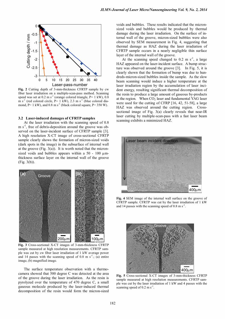
Cutting depth of 3-mm-thickness CFRTP sample was plotted as the function of the laser pass-number (Fig. 2). Linear relation between the cutting depth and laser pass-number was obtained at four different irradiation condi-tions. On the three different scanning speed of the laser beam on the CFRTP surface at the laser power of 1 kW, a fast scan required a large scan-pass-number.
The total laser dose energy on CFRTP surface at the scanning speed of 0.8 m s-1 with 350 W corresponded to the energy at 2.3 m s-1 with 1 kW. The laser-pass-number for the complete cutting at 0.8 m s-1 with 350 W was almost same as that at 2.3 m s-1 with 1 kW. In addition, the inci-dent kerf of the groove formed by the scanning at 2.3 m s-1 with 1 kW was narrow in comparison with at 0.8 m s-1 with 1 kW (Fig.1: Observation (I)). The fast scanning was ef-fective for the reducing the incident kerf region.
These results indicate that a constant value of etching rate for the laser pass-number on CFRTP samples would be acquired on the cw fiber laser irradiation. The depth of the groove on CFRTP sample would be possible to be precisely controlled by the laser pass-number.
Observation (II)direction
Beam scan speed: 0.8 m/s (complete cutting:14 passes)
Beam scan speed: 2.3 m/s (complete cutting: 42 passes)
XCT image
13 passes12 passes
0 pass
1 2 3 4 5 6 7 8 9 10 11 12 13
cw fiber laser CFRTP
Observation (I)direction
Observation
(I)
(II)3 mm
0 pass
Observation
(I)
(II)3 mm
1 2 3 5 10 15 20 30 40
2 passes
10 passes
6 passes
40 passes30 passes20 passes
300mm
300mm
Fig. 1 Cross-sectional X-CT images of 3-mm-thickness CFRTP sample measured at two different observation directions ((I) and (II)). CFRTP sample was cut by cw fiber laser irradiation of 1 kW average power with the scanning speed of 0.8 m s-1 and 2.3 m s-1.
JLMN-Journal of Laser Micro/Nanoengineering Vol. 9, No. 2, 2014
182
-3
-2.5
-2
-1.5
-1
-0.5
0
0 5 10 15 20 25 30 35 40
Cut
ting
dept
h / m
m
Laser-pass-number Fig. 2 Cutting depth of 3-mm-thickness CFRTP sample by cw fiber laser irradiation on a multiple-scan-pass method. Scanning speed was set at 0.2 m s-1 (orange colored triangle, P= 1 kW), 0.8 m s-1 (red colored circle, P= 1 kW), 2.3 m s-1 (blue colored dia-mond, P= 1 kW), and 0.8 m s-1 (black colored square, P= 350 W). 3.2 Laser-induced damages of CFRTP samples
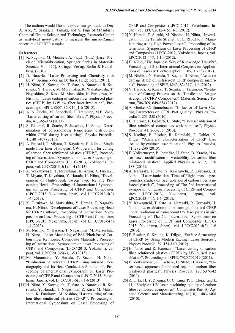
At the laser irradiation with the scanning speed of 0.8 m s-1, free of debris-deposition around the groove was ob-served on the laser-incident surface of CFRTP sample [3]. A high resolution X-CT image of cross-sectional CFRTP sample clearly shows the formation of micron-sized voids (dark spots in the image) in the subsurface of internal wall at the groove (Fig. 3(a)). It is worth noted that the micron-sized voids and bubbles appears within a 50 - 100 mm-thickness surface layer on the internal wall of the groove (Fig. 3(b)).
Fig. 3 Cross-sectional X-CT images of 3-mm-thickness CFRTP sample measured at high resolution measurements. CFRTP sam-ple was cut by cw fiber laser irradiation of 1 kW average power and 14 passes with the scanning speed of 0.8 m s-1.; (a) entire image, (b) magnified image.
The surface temperature observation with a thermo-camera showed that 500 degree C was detected at the area of the groove during the laser irradiation. As the resin is pyrolyzed over the temperature of 470 degree C, a small gaseous molecule produced by the laser-induced thermal decomposition of the resin would form the micron-sized
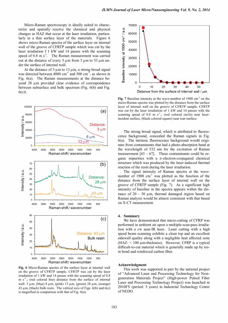
voids and bubbles. These results indicated that the micron-sized voids and bubbles would be produced by thermal damage during the laser irradiation. On the surface of in-ternal wall of the groove, micron-sized bubbles were also observed by SEM measurement in Fig. 4, suggesting that thermal damage as HAZ during the laser irradiation of CFRTP sample occurs in a nearly negligible thin surface layer of the internal wall of the groove.
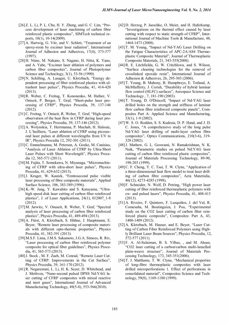
At the scanning speed changed to 0.2 m s-1, a large HAZ appeared on the laser-incident surface. A bump struc-ture was observed around the groove [3]. In Fig. 5, it is clearly shown that the formation of bump was due to hun-dreds-micron-sized bubbles inside the sample. As the slow beam scanning would induce a higher temperature at the laser irradiation region by the accumulation of laser inci-dent energy, resulting significant thermal decomposition of the resin to produce a large amount of gaseous by-products at the region. When CO2 laser and fundamental YAG laser were used for the cutting of CFRP [16, 42, 51-58], a large HAZ was observed around the cutting region. Cross-sectional image of Fig. 3(a) clearly reveals that near-IR laser cutting by multiple-scan-pass with a fast laser beam scanning exhibits a minimized HAZ.
Fig. 4 SEM image of the internal wall surface on the groove of CFRTP sample. CFRTP was cut by the laser irradiation of 1 kW and 14 passes with the scanning speed of 0.8 m s-1.
Fig. 5 Cross-sectional X-CT images of 3-mm-thickness CFRTP sample measured at high resolution measurements. CFRTP sam-ple was cut by the laser irradiation of 1 kW and 4 passes with the scanning speed of 0.2 m s-1.
200mm 100mm
Groove (a) (b)
400mm
Groove
Laser beam incident direction
400mm
JLMN-Journal of Laser Micro/Nanoengineering Vol. 9, No. 2, 2014
183
Micro-Raman spectroscopy is ideally suited to charac-terize and spatially resolve the chemical and physical changes as HAZ that occur at the laser irradiation, particu-larly in a thin surface layer of the materials. Figure 6 shows micro-Raman spectra of the surface layer on internal wall of the groove of CFRTP sample which was cut by the laser irradiation f 1 kW and 14 passes with the scanning speed of 0.8 m s-1. The Raman measurement was carried out at the distance of every 5 mm from 3 mm to 53 mm un-der the surface of internal wall.
At the distance of 3 mm to 13 mm, a strong broad signal was detected between 4000 cm-1 and 500 cm-1, as shown in Fig. 6(a). The Raman measurements at the distance be-yond 28 mm provided clear evidence of correspondence between subsurface and bulk spectrum (Fig. 6(b) and Fig. 6(c)).
0
20000
40000
60000
80000
100000
0 500 1000 1500 2000 2500 3000 3500 4000
Inte
nsity
/ a.u
.
Raman shift / wavenumber
0
10
20
30
40
50
60
70
0 500 1000 1500 2000 2500 3000 3500 4000
Inte
nsity
/ a.u
.
Raman shift / wavenumber
0
10
20
30
40
50
60
0 500 1000 1500 2000 2500 3000 3500 4000
Inte
nsity
/ a.u
.
Raman shift / wavenumber Fig. 6 Micro-Raman spectra of the surface layer at internal wall on the groove of CFRTP sample. CFRTP was cut by the laser irradiation of 1 kW and 14 passes with the scanning speed of 0.8 m s-1.; (red colored line) distance from the surface of internal wall: 3 mm, (blue) 8 mm, (pink) 13 mm, (green) 28 mm, (orange) 43 mm, (black) bulk resin. The vertical axis of Figs. 6(b) and 6(c) is magnified in comparison with that of Fig. 6(a).
Fig. 7 Baseline intensity at the wave-number of 1900 cm-1 on the micro-Raman spectra was plotted by the distance from the surface layer of internal wall on the groove of CFRTP sample. CFRTP was cut by the laser irradiation of 1 kW and 14 passes with the scanning speed of 0.8 m s-1.; (red colored circle) near laser-incident surface, (black colored square) near rear-surface.
The strong broad signal, which is attributed to fluores-
cence background, concealed the Raman signals in Fig. 6(a). The intrinsic fluorescence background would origi-nate from contaminants that had a photo-absorption band at the wavelength of 532 nm for the excitation of Raman measurement [65 – 67]. These contaminants could be or-ganic impurities with a π-electron-conjugated chemical structure which was produced by the laser-induced thermal reaction of the resin during the laser irradiation.
The signal intensity of Raman spectra at the wave-number of 1900 cm-1 was plotted as the function of the distance from the surface layer of internal wall on the groove of CFRTP sample (Fig. 7). As a significant high intensity of baseline in the spectra appears within the dis-tance of 20 - 30 mm, thermal damaged region based on Raman analysis would be almost consistent with that based on X-CT measurement.
4. Summary We have demonstrated that micro-cutting of CFRP was
performed in ambient air upon a multiple-scan-pass irradia-tion with a cw near-IR laser. Laser cutting with a high speed beam scanning exhibits a clean top and an excellent sidewall quality along with a negligible heat affected zone (HAZ: < 100 mm-thickness). However, CFRP is a typical difficult-to-cut material which is generally made up by res-in bond and reinforced carbon fiber.
Acknowledgment This work was supported in part by the national project
of “Advanced Laser and Processing Technology for Next-generation Materials Project” (High-power Pulsed Fiber Laser and Processing Technology Project) was launched in 2010FY (period: 5 years) in Industrial Technology Center of NEDO.
(a)
(b)
(c)
Distance: 3 mm
8 mm 13 mm
43 mm
Distance: 43 mm
Distance: 28 mm
Bulk resin
JLMN-Journal of Laser Micro/Nanoengineering Vol. 9, No. 2, 2014
184
The authors would like to express our gratitude to Drs. A. Abe, Y. Sasaki, T. Tamaki, and Y. Fujii of Mitsubishi Chemical Group Science and Technology Research Center as analytical investigators to measure the micro-Raman spectrum of CFRTP samples.
References [1] K. Sugioka, M. Meunier, A. Piqué, (Eds.) [Laser Pre-
cision Microfabrication, Springer Series in Materials Science, Vol. 135], Springer-Verlag, Berlin & Heidel-berg, (2010).
[2] D. Bauerle, “Laser Processing and Chemistry (4th Ed.)”, Springer-Verlag, Berlin & Heidelberg, (2011).
[3] H. Niino, Y. Kawaguchi, T. Sato, A. Narazaki, R. Ku-rosaki, Y. Harada, M. Muramatsu, K. Wakabayashi, T. Nagashima, Z. Kase, M. Matsushita, K. Furukawa, M. Nishino, “Laser cutting of carbon fiber reinforced plas-tics (CFRP) by 1kW cw fiber laser irradiation”, Pro-ceeding of SPIE, 8607, 860714_1-6 (2013).
[4] A. N. Fuchs, M. Schoeberl, J. Tremmer, M.F. Zaeh, “Laser cutting of carbon fiber fabrics”, Physics Proce-dia, 41, 365-373 (2013).
[5] S. Bluemel, R. Staehr, P. Jaeschke, U. Stute, “Deter-mination of corresponding temperature distribution within CFRP during laser cutting”, Physics Procedia, 41, 401-407 (2013).
[6] A. Fujisaki, T. Miyato, T. Kayahara, H. Niino, “Single mode fiber laser of its quasi CW operation for cutting of carbon fiber reinforced plastics (CFRP)”, Proceed-ing of International Symposium on Laser Processing of CFRP and Composites (LPCC-2013, Yokohama, Ja-pan), vol. LPCC2013-5(1), 1-4 (2013).
[7] K. Wakabayashi, T. Nagashima, K. Anzai, A. Fujisaki, T. Miyato, T. Kayahara, Y. Harada, H. Niino, “Devel-opment of High-Speed, Sweep Type Remote Pro-cessing Head”, Proceeding of International Symposi-um on Laser Processing of CFRP and Composites (LPCC-2013, Yokohama, Japan), vol. LPCC2013-5(2), 1-4 (2013).
[8] K. Furukawa, M. Matsushita, Y. Harada, T. Nagashi-ma, H. Niino, “Development of Laser Processing Head for CFRP Cutting”, Proceeding of International Sym-posium on Laser Processing of CFRP and Composites (LPCC-2013, Yokohama, Japan), vol. LPCC2013-5(3), 1-4 (2013).
[9] M. Nishino, Y. Harada, T. Nagashima, M. Matsushita, H. Niino, “Laser Machining of PAN/Pitch-based Car-bon Fiber Reinforced Composite Materials”, Proceed-ing of International Symposium on Laser Processing of CFRP and Composites (LPCC-2013, Yokohama, Ja-pan), vol. LPCC2013-5(4), 1-5 (2013).
[10] M. Muramatsu, Y. Harada, T. Suzuki, H. Niino, “Evaluation of Defect in CFRP Using Infrared Ther-mography and Its Heat Conduction Simulation”, Pro-ceeding of International Symposium on Laser Pro-cessing of CFRP and Composites (LPCC-2013, Yoko-hama, Japan), vol. LPCC2013-5(5), 1-6 (2013).
[11] H. Niino, Y. Kawaguchi, T. Sato, A. Narazaki, R. Ku-rosaki, Y. Harada, T. Nagashima, Z. Kase, M. Matsu-shita, K. Furukawa, M. Nishino, “Laser cutting of car-bon fiber reinforced plastics (CFRP)”, Proceeding of International Symposium on Laser Processing of
CFRP and Composites (LPCC-2012, Yokohama, Ja-pan), vol. LPCC2012-4(5), 1-8 (2012).
[12] Y. Harada, T. Suzuki, M. Nishino, H. Niino, “Investi-gation on the Tensile Strength of CFRP/CFRTP Manu-facturing using High-Power Lasers”, Proceeding of In-ternational Symposium on Laser Processing of CFRP and Composites (LPCC-2012, Yokohama, Japan), vol. LPCC2012-4(4), 1-10 (2012).
[13] H. Niino, "The Japanese Way of Knowledge Transfer", Proceeding of 31st International Congress on Applica-tions of Lasers & Electro–Optics, C105, 31-33 (2012).
[14] M. Nishino, Y. Harada, T. Suzuki, H. Niino, “Acoustic damage detection in laser-cut CFRP composite materi-als”, Proceeding of SPIE, 8243, 82431C_1-6 (2012).
[15] Y. Harada, K. Kawai, T. Suzuki, T. Teramoto, “Evalu-ation of Cutting Process on the Tensile and Fatigue strength of CFRP Composites”, Materials Science Fo-rum, 706-709, 649-654 (2012).
[16] A. Goeke, C. Emmelmann, “Influence of Laser Cut-ting Parameters on CFRP Part Quality”, Physics Pro-cedia 5, 253-258 (2010).
[17] H. Dittmar, F. Gäblerb, U. Stute, “UV-laser ablation of fibre reinforced composites with ns-pulses”, Physics Procedia, 41, 266-275 (2013).
[18] S. Kreling, F. Fischer, R. Delmdahl, F. Gäbler, K. Dilger, “Analytical characterization of CFRP laser treated by excimer laser radiation”, Physics Procedia, 41, 282-290 (2013).
[19] F. Völkermeyer, P. Jaeschke, U. Stute, D. Kracht, “La-ser-based modification of wettablility for carbon fiber reinforced plastics”, Applied Physics A, A112, 179-183 (2013).
[20] A. Narazaki, T. Sato, Y. Kawaguchi, R. Kurosaki, H. Niino, “Laser-ionization Time-of-Flight mass spec-trometric studies on laser ablation of carbon fiber rein-forced plastics”, Proceeding of The 2nd International Symposium on Laser Processing of CFRP and Compo-sites (LPCC-2013, Yokohama, Japan), vol. LPCC2013-4(1), 1-6 (2013).
[21] Y. Kawaguchi, T. Sato, A. Narazaki, R. Kurosaki, H. Niino, “Laser ablation plume from graphite and CFRP under irradiation of nanosecond UV laser pulses in air”, Proceeding of The 2nd International Symposium on Laser Processing of CFRP and Composites (LPCC-2013, Yokohama, Japan), vol. LPCC2013-4(2), 1-6 (2013).
[22] F. Fischer, S. Kreling, K. Dilger, “Surface Structuring of CFRP by Using Modern Excimer Laser Sources”, Physics Procedia, 39, 154-160 (2012).
[23] H. Niino and R. Kurosaki, “Laser cutting of carbon fiber reinforced plastics (CFRP) by UV pulsed laser ablation”, Proceedings of SPIE, 7920,792019 (2011).
[24] F. Völkermeyer, F. Fischere, U. Stute, D. Kracht, “La-ser-based approach for bonded repair of carbon fiber reinforced plastics”, Physics Procedia, 12, 537-542 (2011).
[25] Z. L. Li, H. Y. Zhenga, G. C. Lima, P. L. Chua, and L. Li, “Study on UV laser machining quality of carbon fibre reinforced composites”, Composites Part A: Ap-plied Science and Manufacturing, 41(10), 1403-1408 (2010).
JLMN-Journal of Laser Micro/Nanoengineering Vol. 9, No. 2, 2014
185
[26] Z. L. Li, P. L. Chu, H. Y. Zheng, and G. C. Lim, “Pro-cess development of laser machining of carbon fibre reinforced plastic composites”, SIMTech technical re-ports, 10(1), 10-14(2009).
[27] A. Hartwig, G. Vitr, and V. Schlett, “Treatment of an epoxy-resin by excimer laser radiation”, International Journal of Adhesion and Adhesives, 17(4), 373-377 (1997).
[28] H. Niino, M. Nakano, S. Nagano, H. Nitta, K. Yano, and A. Yabe, “Excimer laser ablation of polymers and carbon fiber composites”, Journal of Photopolymer Science and Technology, 3(1), 53-56 (1990).
[29] N. Schilling, A. Lasagni, U. Klotzbach, “Energy de-pendent processing of fiber reinforced plastics with ul-trashort laser pulses”, Physics Procedia, 41, 414-420 (2013).
[30] R. Weber, C. Freitag, T. Kononenko, M. Hafner, V. Oniseit, P. Berger, T. Graf, “Short-pulse laser pro-cessing of CFRP”, Physics Procedia, 39, 137-146 (2012).
[31] C. Freitag, V. Oniseit, R. Weber, T. Graf, “High-speed observation of the heat flow in CFRP during laser pro-cessing”, Physics Procedia, 39, 137-146 (2012).
[32] A. Wolynskia, T. Herrmanna, P. Muchab, H. Halouic, J. L’huilliera, “Laser ablation of CFRP using picosec-ond laser pulses at different wavelengths from UV to IR”, Physics Procedia 12, 292-301 (2011).
[33] C. Emmelmanna, M. Petersen, A. Goeke, M. Canisius, “Analysis of Laser Ablation of CFRP by Ultra-Short Laser Pulses with Short Wavelength”, Physics Proce-dia 12, 565-571 (2011).
[34] M. Fujita, T. Somekawa, N. Miyanaga, “Micromachin-ing of CFRP with ultra-short laser pulses”, Physics Procedia, 41, 629-632 (2013).
[35] J. Kruger, W. Kautek, “Femtosecond pulse visible laser processing of fibre composite materials”, Applied Surface Science, 106, 383-389 (1996).
[36] K.-W. Jung, Y. Kawahito and S. Katayama, “Ultra-high speed disk laser cutting of carbon fiber reinforced plastics”, J. of Laser Applications, 24(1), 012007_1-8 (2012).
[37] M. Jarwitz, V. Onuseit, R. Weber, T. Graf, “Spectral analysis of laser processing of carbon fiber reinforced plastics”, Physics Procedia, 41, 489-494 (2013).
[38] A. Fürst, A. Klotzbach, S. Hühne, J. Hauptmann, E. Beyer, “Remote laser processing of composite materi-als with different opto-thermic properties”, Physics Procedia, 41, 382-391 (2013).
[39] M.S.F. Lima, J.M.S. Sakamoto, J.G.A. Simoes, R. Riv, “Laser processing of carbon fiber reinforced polymer composite for optical fiber guidelines”, Physics Proce-dia, 41, 565-573 (2013).
[40] J. Stock , M. F. Zaeh, M. Conrad, “Remote Laser Cut-ting of CFRP: Improvements in the Cut Surface”, Physics Procedia, 39, 161-170 (2012).
[41] R. Negarestani, L. Li, H. K. Sezer, D. Whitehead, and J. Methven, “Nano-second pulsed DPSS Nd:YAG la-ser cutting of CFRP composites with mixed reactive and inert gases”, International Journal of Advanced Manufacturing Technology, 49(5-8), 553-566(2010).
[42] D. Herzog, P. Jaeschke, O. Meier, and H. Haferkamp, “Investigations on the thermal effect caused by laser cutting with respect to static strength of CFRP”, Inter-national Journal of Machine Tools & Manufacture, 48, 1464-1473 (2008).
[43] T. M. Young, “Impact of Nd-YAG Laser Drilling on the Fatigue Characteristics of APC-2A/AS4 Thermo-plastic Composite Material”, Journal of Thermoplastic Composite Materials, 21, 543-555(2008).
[44] R. E. Litchfielda, G. W. Critchlowa, and S. Wilson, “Surface cleaning technologies for the removal of crosslinked epoxide resin”, International Journal of Adhesion & Adhesives, 26, 295-303 (2006).
[45] T. Young, B. Mahony, B. Humphreys, E. Totland, A. McMlafferty, J. Corish, “Durability of hybrid laminar flow control (HLFC) surfaces”, Aerospace Science and Technology , 7, 181-190 (2003).
[46] T. Young, D. O'Driscoll, “Impact of Nd-YAG laser drilled holes on the strength and stiffness of laminar flow carbon fibre reinforced composite panels”, Com-posites Part A: Applied Science and Manufacturing, 33(1), 1-9 (2002).
[47] W. S. O. Rodden, S. S. Kudesia, D. P. Hand, and J. D. C. Jones, “A comprehensive study of the long pulse Nd:YAG laser drilling of multi-layer carbon fibre composites”, Optics Communications, 210(3-6), 319-328 (2002).
[48] J. Mathew, G. L. Goswami, N. Ramakrishnan, N. K. Naik, “Parametric studies on pulsed Nd:YAG laser cutting of carbon fibre reinforced plastic composites”, Journal of Materials Processing Technology, 89-90, 198-203 (1999).
[49] C. F. Cheng, Y. C. Tsui, T. W. Clyne, “Application of a three-dimensional heat flow model to treat laser drill-ing of carbon fibre composites”, Acta Materialia, 46(12), 4273-4285 (1998).
[50] F. Schneider, N. Wolf, D. Petring, “High power laser cutting of fiber reinforced thermoplastic polymers with cw- and pulsed lasers”, Physics Procedia, 41, 408-413 (2013).
[51] A. Riveiro, F. Quintero, F. Lusquiños, J. del Val, R. Comesaña, M. Boutinguiza, J. Pou, “Experimental study on the CO2 laser cutting of carbon fiber rein-forced plastic composite”, Composites: Part A, 43, 1400-1409 (2012).
[52] A. Klotzbach, M. Hauser, and E. Beyer, “Laser Cut-ting of Carbon Fiber Reinforced Polymers using High-ly Brilliant Laser Beam Sources”, Physics Procedia, 12, 572-577 (2011).
[53] F. A. Al-Sulaiman, B. S. Yilbas, , and M. Ahsan, “CO2 laser cutting of a carbon/carbon multi-lamelled plain-weave structure”, Journal of Materials Pro-cessing Technology, 173, 345-351(2006).
[54] T. J. Matthams, T. W. Clyne, “Mechanical properties of long-fibre thermoplastic composites with laser drilled microperforations 1. Effect of perforations in consolidated material”, Composites Science and Tech-nology, 59(8), 1169-1180 (1999).
JLMN-Journal of Laser Micro/Nanoengineering Vol. 9, No. 2, 2014
186
[55] T. J. Matthams, T. W. Clyne, “Mechanical properties of long-fibre thermoplastic composites with laser drilled microperforations 2. Effect of prior plastic strain”, Composites Science and Technology, 59(8), 1181-1187 (1999).
[56] E. Uhlmann, G.S pur, H. Hocheng, S. Leibelt, C. T. Pan, “The extent of laser-induced thermal damage of UD and crossply composite laminates”, International Journal of Machine Tools & Manufacture, 39, 639-650(1999).
[57] A. Hartwig, G. Vitr, S. Dieckhoff', and O. -D. Henne-mann, “Surface treatment of an epoxy resin by CO2 laser irradiation”, Die Angewandte Makromolekulare Chemie, 238, 177-189 (1996).
[58] V. Tagliaferri, A. Di Ilio, C.Visconti, “Laser cutting of fibre-reinforced polyesters”, Composites, 16(4), 317-325 (1985).
[59] R. Weber, M. Hafner, A. Michalowski, T. Graf, “Min-imum Damage in CFRP Laser Processing”, Physics Procedia 12, 302-307 (2011).
[60] A. A. Cenna, P. Mathew, “Analysis and prediction of laser cutting parameters of fibre reinforced plastics (FRP) composite materials”, International Journal of Machine Tools & Manufacture, 42(1), 105-113(2002).
[61] C. T. Pan, H. Hocheng, “Evaluation of anisotropic thermal conductivity for unidirectional FRP in laser machining”, Composites: Part A, 32(11), 1657-1667 (2001).
[62] A. A. Cenna, P. Mathew, “Evaluation of cut quality of fibre-reinforced plastics-A review”, International Jour-nal of Machine Tools & Manufacture, 37(6), 723-736(1997).
[63] G. Caprino, V. Tagliaferri, “Maximum cutting speed in laser cutting of fibre reinforced plastics”, Interna-tional Journal of Machine Tools & Manufacture, 28(4), 389-398(1988).
[64] Mitsubishi Engineering Plastics: Iupilon; Product In-formation and Material Safety Data Sheet (MSDS); URL http://www.m-ep.co.jp/en/product/brand/
[65] Perkin Elmer Inc., “Introduction to Raman Spectrosco-py: Top 20 Questions Answered (2007)”; URL www.perkinelmer.com.
[66] D. V. Martyshkin, R. C. Ahuja, A. Kudriavtsev, S. B. Mirov, “Effective suppression of fluorescence light in Raman measurements using ultrafast time gated charge coupled device camera”, Review of Scientific Instru-ments, 75(39), 630-635(2004).
[67] P. M. Donaldson, K. R. Willison, David R. Klug, “Generation of Simplified Protein Raman Spectra Us-ing Three-Color Picosecond Coherent Anti-Stokes Raman Spectroscopy”, J. Phys. Chem. B, 114(37), 12175–12181(2010).
(Received: August 19, 2013, Accepted: June 4, 2014)