Embed Size (px)
Citation preview
Laurea Magistrale in Ingegneria
Informatica
A Cloud based Reinforcement LearningFramework for humanoid grasping
Laureando: Relatore:Alejandro Gatto Prof. Enrico Pagello
Correlatore:Dott.ssa Elisa Tosello
Anno Accademico 2015 - 2016
Universita degli Studi di PadovaScuola di Ingegneria
Dipartimento di Ingegneria
dell’InformazioneLaurea Magistrale in Ingegneria Informatica
A Cloud based Reinforcement LearningFramework for humanoid grasping
Laureando: Relatore:Alejandro Gatto Prof. Enrico Pagello
Correlatore:Dott.ssa Elisa Tosello
Anno Accademico 2015 - 2016
Abstract
This work presents an innovative approach to a common task onrobotics: grasping a set of objects.
Grasping is one of the earliest and most common tasks developedin robotics.
Modern-day robots can be carefully hand-programmed to carry outmany complex manipulation tasks. However, autonomously grasp-ing a previously unknown object still remains a challenging prob-lem. This Thesis presents a new framework, inspired by the classi-cal sense-model-act architecture and the knowledge processing ofCognitive Robotics. The framework tries to generalize the grasp-ing task to a generic action, where Reinforcement Learning andCloud Robotics play an important role.
In fact, the sense module receives the input from RGB-D sensorsand uses state-of-art vision algorithms for segmentation and detectionof objects in point clouds.
The model module takes the input from the sense node and usesa novel Reinforcement learning algorithm that improves the internalmodel by using the experience of past actions in a particular manner:it stores the experience information in an ontology database that canalso be used by other robots performing the same task. Ontologycommunication is done by using modern web-application standards inorder to generalize and scale better the system. The grasping actionitself uses another state-of-art algorithm. It takes the input objectand the gripper’s geometry and it generates some high-level graspingposes. These poses are then filtered by the learning algorithm.
Finally, the act module takes the model ’s output and executesthe motion planning algorithm to complete the task.
This architecture is very modular and can be easily adapted toperform different tasks or to execute them on other robots.
1
Contents
1 Introduction 61.1 Objectives . . . . . . . . . . . . . . . . . . . . . . . . . . . . . 61.2 Thesis’s structure . . . . . . . . . . . . . . . . . . . . . . . . . 61.3 Introduction to the sense-model-act framework . . . . . . . . . 81.4 Software - ROS Middleware . . . . . . . . . . . . . . . . . . . 91.5 Software - the Gazebo simulator . . . . . . . . . . . . . . . . . 11
1.5.1 Modifying the Nao’s URDF model . . . . . . . . . . . 12
2 The sense module 162.1 Software - The Point Cloud Library . . . . . . . . . . . . . . . 182.2 Software - The OpenCV library . . . . . . . . . . . . . . . . . 182.3 Hardware - The RGB-D sensor . . . . . . . . . . . . . . . . . 192.4 Tabletop object detection problem . . . . . . . . . . . . . . . . 202.5 Point cloud Segmentation . . . . . . . . . . . . . . . . . . . . 21
2.5.1 The supervoxel concept . . . . . . . . . . . . . . . . . . 232.5.2 Segmentation algorithm . . . . . . . . . . . . . . . . . 252.5.3 LCCP algorithm . . . . . . . . . . . . . . . . . . . . . 25
2.6 The sense module package implementation . . . . . . . . . . . 272.7 The image’s descriptors . . . . . . . . . . . . . . . . . . . . . . 29
2.7.1 HOG . . . . . . . . . . . . . . . . . . . . . . . . . . . . 302.7.2 SIFT . . . . . . . . . . . . . . . . . . . . . . . . . . . . 30
3 The model module 323.1 The model package . . . . . . . . . . . . . . . . . . . . . . . . 323.2 Cloud Robotics . . . . . . . . . . . . . . . . . . . . . . . . . . 33
3.2.1 Related work and state-of-art developments . . . . . . 343.2.2 Introduction to ontologies . . . . . . . . . . . . . . . . 343.2.3 The proposed RTASK ontology . . . . . . . . . . . . . 353.2.4 The implemented Cloud-based Engine . . . . . . . . . 37
3.3 Reinforcement learning . . . . . . . . . . . . . . . . . . . . . . 423.3.1 Introduction . . . . . . . . . . . . . . . . . . . . . . . . 423.3.2 Main Reinforcement Learning algorithms . . . . . . . . 453.3.3 Related works - learning and grasping . . . . . . . . . . 473.3.4 The Reinforcement learning package . . . . . . . . . . 48
2
4 The act module 524.1 Hardware - The Aldebaran Nao . . . . . . . . . . . . . . . . . 524.2 Software - The Moveit! library . . . . . . . . . . . . . . . . . . 544.3 The Act ROS package . . . . . . . . . . . . . . . . . . . . . . 57
5 Experiments 625.1 Recognition engine . . . . . . . . . . . . . . . . . . . . . . . . 625.2 Grasping experiments . . . . . . . . . . . . . . . . . . . . . . . 64
6 Conclusions and further work 65
7 Ringraziamenti 67
3
List of Figures
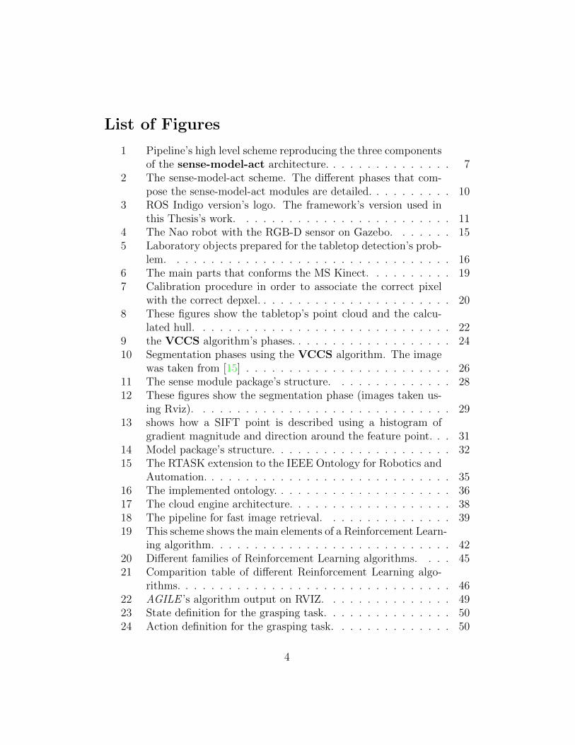
1 Pipeline’s high level scheme reproducing the three componentsof the sense-model-act architecture. . . . . . . . . . . . . . . 7
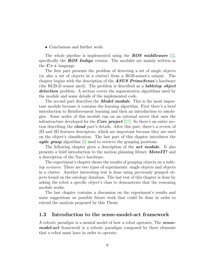
2 The sense-model-act scheme. The different phases that com-pose the sense-model-act modules are detailed. . . . . . . . . . 10
3 ROS Indigo version’s logo. The framework’s version used inthis Thesis’s work. . . . . . . . . . . . . . . . . . . . . . . . . 11
4 The Nao robot with the RGB-D sensor on Gazebo. . . . . . . 155 Laboratory objects prepared for the tabletop detection’s prob-
lem. . . . . . . . . . . . . . . . . . . . . . . . . . . . . . . . . 166 The main parts that conforms the MS Kinect. . . . . . . . . . 197 Calibration procedure in order to associate the correct pixel
with the correct depxel. . . . . . . . . . . . . . . . . . . . . . . 208 These figures show the tabletop’s point cloud and the calcu-
lated hull. . . . . . . . . . . . . . . . . . . . . . . . . . . . . . 229 the VCCS algorithm’s phases. . . . . . . . . . . . . . . . . . . 2410 Segmentation phases using the VCCS algorithm. The image
was taken from [15] . . . . . . . . . . . . . . . . . . . . . . . . 2611 The sense module package’s structure. . . . . . . . . . . . . . 2812 These figures show the segmentation phase (images taken us-
ing Rviz). . . . . . . . . . . . . . . . . . . . . . . . . . . . . . 2913 shows how a SIFT point is described using a histogram of
gradient magnitude and direction around the feature point. . . 3114 Model package’s structure. . . . . . . . . . . . . . . . . . . . . 3215 The RTASK extension to the IEEE Ontology for Robotics and
Automation. . . . . . . . . . . . . . . . . . . . . . . . . . . . . 3516 The implemented ontology. . . . . . . . . . . . . . . . . . . . . 3617 The cloud engine architecture. . . . . . . . . . . . . . . . . . . 3818 The pipeline for fast image retrieval. . . . . . . . . . . . . . . 3919 This scheme shows the main elements of a Reinforcement Learn-
ing algorithm. . . . . . . . . . . . . . . . . . . . . . . . . . . . 4220 Different families of Reinforcement Learning algorithms. . . . 4521 Comparition table of different Reinforcement Learning algo-
rithms. . . . . . . . . . . . . . . . . . . . . . . . . . . . . . . . 4622 AGILE ’s algorithm output on RVIZ. . . . . . . . . . . . . . . 4923 State definition for the grasping task. . . . . . . . . . . . . . . 5024 Action definition for the grasping task. . . . . . . . . . . . . . 50
4
25 The humanoid Nao, detailing the different robot’s parts. . . . 5226 Zoom on the right arm joints, detailing the arm’s DOF . . . . 5327 MoveIt! pipeline for motion planning. . . . . . . . . . . . . . . 5528 The Act package’s structure. . . . . . . . . . . . . . . . . . . 5829 Grasping’s simulation using the implemented Act package. . . 5930 Detail on the interface of the node Act. . . . . . . . . . . . . . 6031 Real Nao robot before performing the grasping task. . . . . . . 65
5
1 Introduction
1.1 Objectives
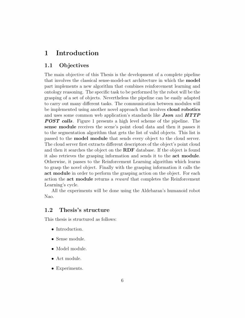
The main objective of this Thesis is the development of a complete pipelinethat involves the classical sense-model-act architecture in which the modelpart implements a new algorithm that combines reinforcement learning andontology reasoning. The specific task to be performed by the robot will be thegrasping of a set of objects. Nevertheless the pipeline can be easily adaptedto carry out many different tasks. The communication between modules willbe implemented using another novel approach that involves cloud roboticsand uses some common web application’s standards like Json and HTTPPOST calls. Figure 1 presents a high level scheme of the pipeline. Thesense module receives the scene’s point cloud data and then it passes itto the segmentation algorithm that gets the list of valid objects. This list ispassed to the model module that sends every object to the cloud server.The cloud server first extracts different descriptors of the object’s point cloudand then it searches the object on the RDF database. If the object is foundit also retrieves the grasping information and sends it to the act module.Otherwise, it passes to the Reinforcement Learning algorithm which learnsto grasp the novel object. Finally with the grasping information it calls theact module in order to perform the grasping action on the object. For eachaction the act module returns a reward that completes the ReinforcementLearning’s cycle.
All the experiments will be done using the Aldebaran’s humanoid robotNao.
1.2 Thesis’s structure
This thesis is structured as follows:
• Introduction.
• Sense module.
• Model module.
• Act module.
• Experiments.
6
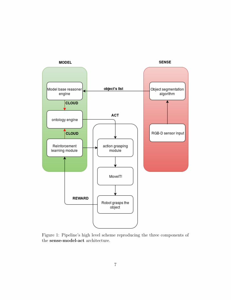
Figure 1: Pipeline’s high level scheme reproducing the three components ofthe sense-model-act architecture.
7
• Conclusions and further work.
The whole pipeline is implemented using the ROS middleware [2],specifically the ROS Indigo version. The modules are mainly written inthe C++ language.
The first part presents the problem of detecting a set of single objects(or also a set of objects in a clutter) from a RGB-sensor’s output. Thechapter begins with the description of the ASUS PrimeSense ’s hardware(the RGB-D sensor used). The problem is described as a tabletop objectdetection problem. A section covers the segmentation algorithms used bythe module and some details of the implemented code.
The second part describes the Model module . This is the most impor-tant module because it contains the learning algorithm. First there’s a briefintroduction to Reinforcement learning and then an introduction to ontolo-gies. Some nodes of this module run on an external server that uses theinfrastructure developed for the Core project [27]. So there’s an entire sec-tion describing the cloud part’s details. After this part, there’s a review of2D and 3D features descriptors, which are important because they are usedon the object’s classification. The last part of this chapter introduces theagile grasp algorithm [6] used to retrieve the grasping positions.
The following chapter gives a description of the act module . It alsopresents a brief introduction to the motion planning library MoveIT! anda description of the Nao’s hardware.
The experiment’s chapter shows the results of grasping objects on a table-top scenario. There are two types of experiments: single objects and objectsin a clutter. Another interesting test is done using previously grasped ob-jects found on the ontology database. The last test of this chapter is done byasking the robot a specific object’s class to demonstrate that the reasoningmodule works.
The last chapter contains a discussion on the experiment’s results andsome suggestions on possible future work that could be done in order toextend the analysis proposed by this Thesis.
1.3 Introduction to the sense-model-act framework
A robotic paradigm is a mental model of how a robot operates, The sense-model-act framework is a robotic paradigm composed by three elementsthat a robot must have in order to operate:
8
• Sense - the robot acquires information about the environment usingthis element. The information is, for example, sensor’s feedback, likeimages, force sensor’s feedback, etc.
• Model - the robot takes the sensed data and have to respond accord-ingly to it. This element creates an action’s sequence (plan) to beexecuted.
• Act - this element executes the action’s sequence generated by the theModel module.
This paradigm was among the first proposed in the 70’s, it implies a closedworld model. The external world’s representation is an idealized model andthe robot is not part of it. The paradigm is useful if the sensing phase isslow, and the environment is static. The act phase should be fast enough inorder to jump immediately to the sense phase again and read new changeson the environment.
The model phase is the real bottleneck of this framework, because themodule may have to handle many states produced by the sense module in-puts. More states means generating more possible actions and then decidethe best action to take at a certain time.
Figure 2 shows the relation between the different phases of the sense-model-act framework. In this case the sensing and action along with theenvironment are showed together in the lower part of the scheme. Thislower part remembers the scheme of another well known machine learningframework: Reinforcement learning. The idea behind this Thesis’s work isto improve the model phase by using Reinforcement learning and to speedup the entire pipeline by using the accumulated knowledge shared on thedatabase that resides on the cloud.
1.4 Software - ROS Middleware
The entire Thesis’s pipeline is implemented using ROS (Robot OperatingSystem).
ROS is a robotics opensource middleware. The main vantage of this mid-dleware is the infrastructure layer, that’s shared by all platforms using theoperating system. In this way there are many of libraries already imple-mented and of easy integration. The robotics community is very active ondeveloping new libraries for this system, so we can find a lot of algorithms,
9
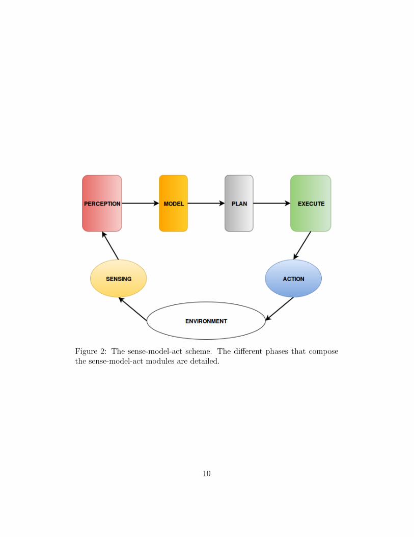
Figure 2: The sense-model-act scheme. The different phases that composethe sense-model-act modules are detailed.
10
Figure 3: ROS Indigo version’s logo. The framework’s version used in thisThesis’s work.
simulations, etc. For a proper introduction to ROS visit the official website([2]). The version used in this Thesis is the Indigo version (figure 3) runningon Ubuntu 14.04 LTS.
1.5 Software - the Gazebo simulator
Gazebo is an open source simulator for robotics1. It offers the ability to ac-curately and efficiently simulate populations of robots in complex indoor andoutdoor environments. It has a robust physics engine, high-quality graphicsand convenient programmatic and graphical interfaces.
Gazebo is compatible with a particular XML file used in ROS as standard,the Universal Robotic Description Format (URDF) that serves to describeall the elements of a robot.
1http://gazebosim.org/
11
1.5.1 Modifying the Nao’s URDF model
The Nao’s ROS model is implemented by the package nao description .This package is necessary to run the real Nao and the virtual Nao. Thissection shows how to modify the nao description package in order to add avirtual kinect that will help later to calculate the distance to objects and touse the simulation on the recognition’s pipeline.
Inside this package there are two files:
• nao sensors.xacro
• naoGazebo.xacro
Note that the file’s extension is not .urdf but .xacro. Xacro is an XMLMacro language which permits to reduce large XML expressions usingsome macro definitions, see2 for details.
These two .xacro files where modified in order to add the RGB-D sensor(kinect) to the robot.
On the first file the following section was added (at the top of the headjoint)
< j o i n t name=” camera depth jo in t ” type=” f i x e d ”><o r i g i n xyz=”0 0 0” rpy=”0 0 0” /><parent l i n k=”CameraDepth3 frame” /><c h i l d l i n k=” camera depth frame ” />
</j o i n t>
< l i n k name=” camera depth frame ”>< i n e r t i a l >
<mass value=” 0 .01 ” /><o r i g i n xyz=”0 0 0” rpy=” 0 .0 0 .0 0 .0 ” />< i n e r t i a ixx=” 0.001 ” ixy=” 0 .0 ” i x z=” 0 .0 ”
iyy=” 0.001 ” iy z=” 0 .0 ”i z z=” 0.001 ” />
</ i n e r t i a l ></l ink>
< j o i n t name=” c a m e r a d e p t h o p t i c a l j o i n t ” type=” f i x e d ”><o r i g i n xyz=”0 0 0” rpy=”0 0 0” /><parent l i n k=” camera depth frame ” /><c h i l d l i n k=” camera depth opt i ca l f rame ” />
</j o i n t>
2http://wiki.ros.org/xacro
12
< l i n k name=” camera depth opt i ca l f rame ”>< i n e r t i a l >
<mass value=” 0.001 ” /><o r i g i n xyz=”0 0 0” rpy=”0 0 0” />< i n e r t i a ixx=” 0.0001 ” ixy=” 0 .0 ” i x z=” 0 .0 ”
iyy=” 0.0001 ” iy z=” 0 .0 ”i z z=” 0.0001 ” />
</ i n e r t i a l ></l ink>
< j o i n t name=” camera rgb jo in t ” type=” f i x e d ”><o r i g i n xyz=”0 −0.005 0” rpy=”0 0 0” /><parent l i n k=”CameraDepth3 frame” /><c h i l d l i n k=” camera rgb frame ” />
</j o i n t>
< l i n k name=” camera rgb frame ”>< i n e r t i a l >
<mass value=” 0.001 ” /><o r i g i n xyz=”0 0 0” />< i n e r t i a ixx=” 0.0001 ” ixy=” 0 .0 ” i x z=” 0 .0 ”
iyy=” 0.0001 ” iy z=” 0 .0 ”i z z=” 0.0001 ” />
</ i n e r t i a l ></l ink>
< j o i n t name=” c a m e r a r g b o p t i c a l j o i n t ” type=” f i x e d ”><o r i g i n xyz=”0 0 0” rpy=”0 0 0” /><parent l i n k=” camera rgb frame ” /><c h i l d l i n k=” camera rgb opt i ca l f r ame ” />
</j o i n t>
< l i n k name=” camera rgb opt i ca l f r ame ”>< i n e r t i a l >
<mass value=” 0.001 ” /><o r i g i n xyz=”0 0 0” />< i n e r t i a ixx=” 0.0001 ” ixy=” 0 .0 ” i x z=” 0 .0 ”
iyy=” 0.0001 ” iy z=” 0 .0 ”i z z=” 0.0001 ” />
</ i n e r t i a l ></l ink>
Note that the origin TAG of the camera rgb joint
< j o i n t name=” camera rgb jo in t ” type=” f i x e d ”>
13
<o r i g i n xyz=”0 −0.005 0” rpy=”0 0 0” /><parent l i n k=”CameraDepth3 frame” /><c h i l d l i n k=” camera rgb frame ” />
</j o i n t>
defines the relative position of the RGB-D sensor to the robot’s head joint.The second file, naoGazebo.xacro add the RGB-D sensor as a virtual
device, so the camera takes the images of the virtual scene and elaboratesthem as real images. The following section was added after the normal RGBcamera’s section:
<gazebo r e f e r e n c e=”CameraDepth3 frame”><s enso r type=”depth” name=” openni camera camera a le ”>
<always on>true</always on><update rate >20.0</ update rate><camera>
<h o r i z o n t a l f o v >1.2</ h o r i z o n t a l f o v ><image>
<format>R8G8B8</format><width>640</width><height >480</height>
</image><c l i p>
<near >0.05</near><f a r >8.0</ far>
</c l i p></camera><plug in name=” k i n e c t c a m e r a c o n t r o l l e r ”f i l ename=” l i b g a z e b o r o s o p e n n i k i n e c t . so ”>
<cameraName>k i n e c t a l e </cameraName><alwaysOn>true</alwaysOn><updateRate>10</updateRate><imageTopicName>/CameraDepth3 frame/ rgb/ image raw</imageTopicName><depthImageTopicName>/CameraDepth3 frame/depth/ image raw</depthImageTopicName><pointCloudTopicName>/CameraDepth3 frame/depth/ po in t s</pointCloudTopicName><cameraInfoTopicName>/CameraDepth3 frame/ rgb/ camera in fo</cameraInfoTopicName><depthImageCameraInfoTopicName>/CameraDepth3 frame/depth/ camera in fo
14
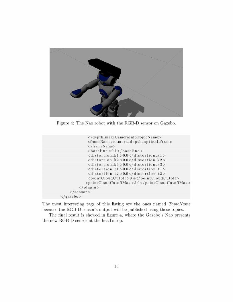
Figure 4: The Nao robot with the RGB-D sensor on Gazebo.
</depthImageCameraInfoTopicName><frameName>camera depth opt i ca l f rame</frameName><base l i n e >0.1</ bas e l i n e><d i s t o r t i o n k 1 >0.0</ d i s t o r t i o n k 1 ><d i s t o r t i o n k 2 >0.0</ d i s t o r t i o n k 2 ><d i s t o r t i o n k 3 >0.0</ d i s t o r t i o n k 3 ><d i s t o r t i o n t 1 >0.0</ d i s t o r t i o n t 1 ><d i s t o r t i o n t 2 >0.0</ d i s t o r t i o n t 2 ><pointCloudCutof f >0.4</ pointCloudCutof f>
<pointCloudCutoffMax >5.0</pointCloudCutoffMax></plugin>
</sensor></gazebo>
The most interesting tags of this listing are the ones named TopicNamebecause the RGB-D sensor’s output will be published using these topics.
The final result is showed in figure 4, where the Gazebo’s Nao presentsthe new RGB-D sensor at the head’s top.
15
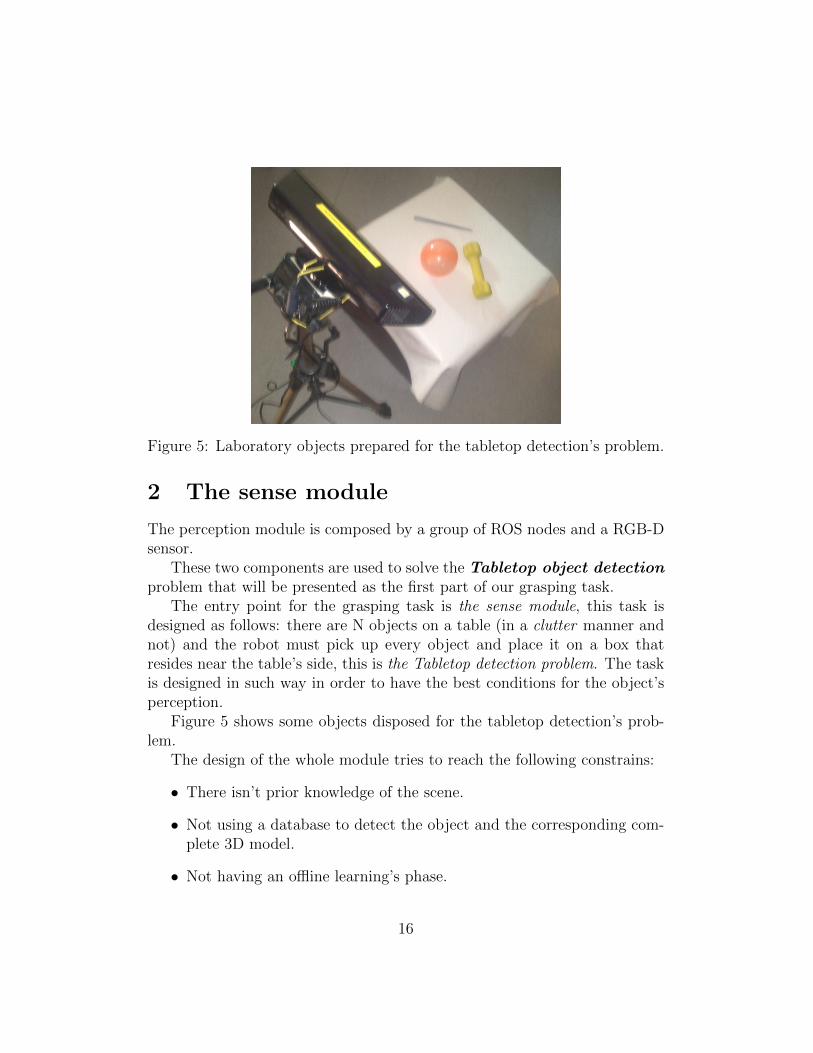
Figure 5: Laboratory objects prepared for the tabletop detection’s problem.
2 The sense module
The perception module is composed by a group of ROS nodes and a RGB-Dsensor.
These two components are used to solve the Tabletop object detectionproblem that will be presented as the first part of our grasping task.
The entry point for the grasping task is the sense module, this task isdesigned as follows: there are N objects on a table (in a clutter manner andnot) and the robot must pick up every object and place it on a box thatresides near the table’s side, this is the Tabletop detection problem. The taskis designed in such way in order to have the best conditions for the object’sperception.
Figure 5 shows some objects disposed for the tabletop detection’s prob-lem.
The design of the whole module tries to reach the following constrains:
• There isn’t prior knowledge of the scene.
• Not using a database to detect the object and the corresponding com-plete 3D model.
• Not having an offline learning’s phase.
16
Some popular alternatives to detect objects are the tabletop object detectormodule3, originally created by Willow Garage for the ROS platform. Thepurpose of this module is to provide a means of recognizing simple householdobjects placed on a table such that they can be manipulated effectively. Thismodule uses a similar algorithm for the segmentation step but in order torecognize an object, it uses a model database, so the module can’t recognizean unknown object and the database is the classical relational SQL database,not well suited for sharing knowledge between robots.
Another popular alternative is the Object recognition kitchen (ORK)framework4 that’s also being developed by the Willow Garage’s team. It’s acomplete framework providing a lot of algorithms for object detection, e.g. fortransparent objects, non textured objects, articulated, etc. It also containsan entire pipeline’s implementation for object detection, giving the databaselayer, input/output handling and more. The problem with this library isthat not provides the latest state-of-art algorithms for object detection andthe database is a classic relational SQL database, being hard to scale andhandle many objects at the same time. Lastly being a complete frameworkit’s not easy to integrate with ROS (but provides some ROS communicationfunctions).
Two interesting works serve as inspiration to the development of thismodule, the first is [18], in this Thesis a complete pipeline is implemented,following the objectives of the present module. A ROS node was releasedcontaining all the implemented code, rail object detection , but the prob-lem is that this node is implemented using an old ROS version and thus partsof the module must be rewritten in order to use it with the INDIGO version.
The second work is [19]. This technical report proposes a similar pipelineto that of the first, but using the latest state-of-art algorithms for segmenta-tion (using the implementation present in the PCL library). This work willbe the starting point of the sense’s module implementation.
Before starting with the sense module’s description the following threesections will explain the tools needed and used on the development of themodule.
3http://wiki.ros.org/tabletop object detector4http://wg-perception.github.io/object recognition core/
17
2.1 Software - The Point Cloud Library
The Point Cloud Library (PCL) is an open source project (BSD license)for 3D geometry processing and point cloud processing. This project wasoriginally develop by Willow Garage in 2010 as a ROS package. The libraryis divided in the following modules:
• filters
• features
• keypoints
• registration
• kdtree
• octree
• segmentation
• sample consensus
• surface
• recognition
• io
• visualization
The PCL is the tool used in this Thesis to work with point clouds thatare the outputs of RGD-D sensors. As stated before, the entire sense moduleuses state-of-art algorithms that are implemented inside the PCL library.
2.2 Software - The OpenCV library
OpenCV (Open Source Computer Vision Library) is a popular open sourcelibrary (using the BSD license) that contains a lot of implementations ofcomputer vision algorithms. It’s cross-platform and although being devel-oped mainly on C++ there are bindings for popular languages like java,python and C#.
18
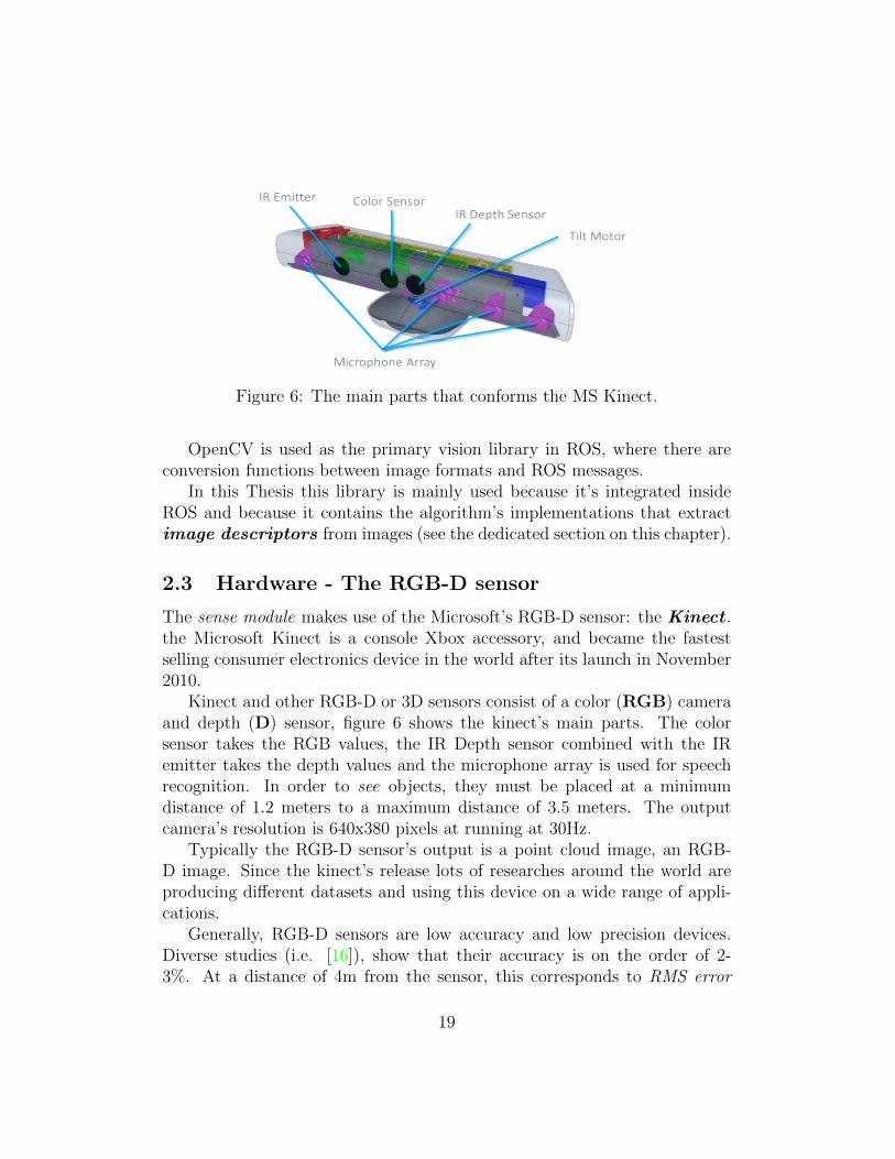
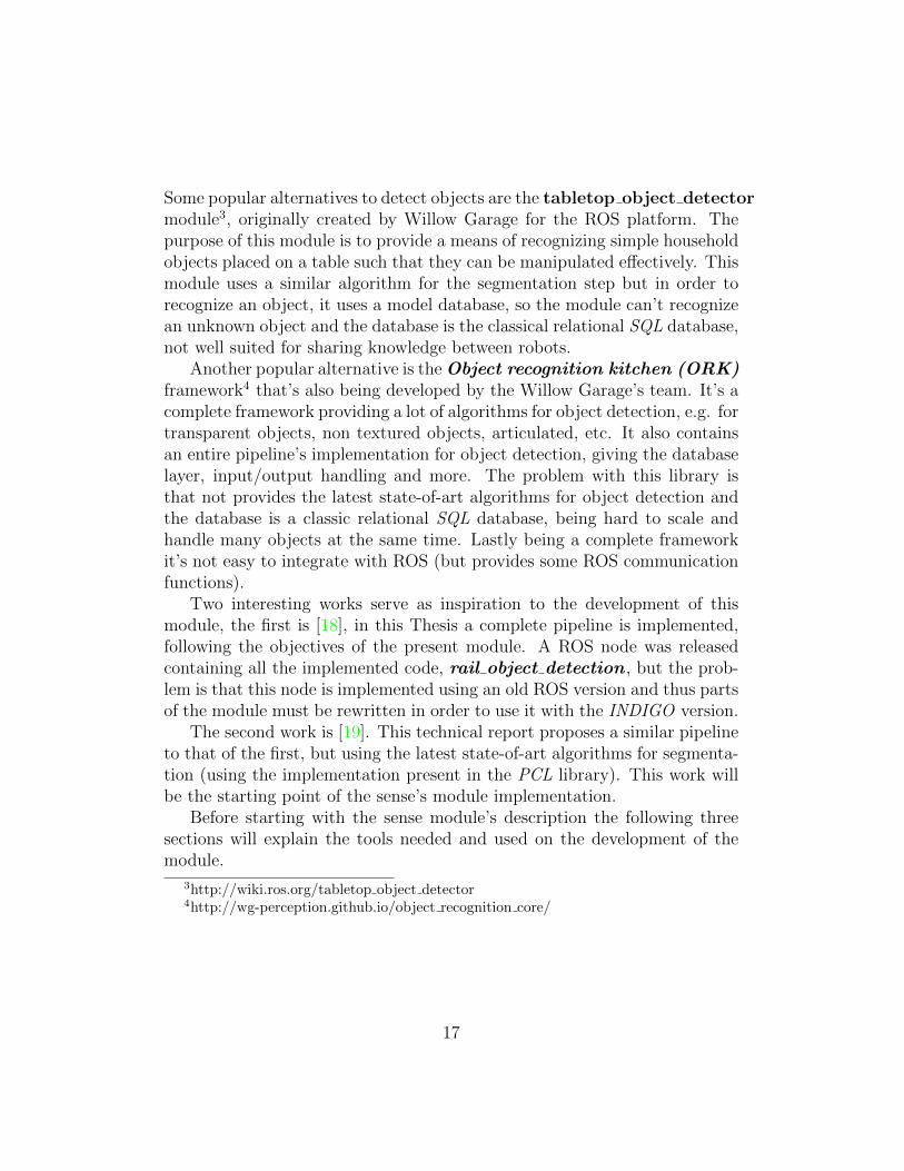
Figure 6: The main parts that conforms the MS Kinect.
OpenCV is used as the primary vision library in ROS, where there areconversion functions between image formats and ROS messages.
In this Thesis this library is mainly used because it’s integrated insideROS and because it contains the algorithm’s implementations that extractimage descriptors from images (see the dedicated section on this chapter).
2.3 Hardware - The RGB-D sensor
The sense module makes use of the Microsoft’s RGB-D sensor: the Kinect .the Microsoft Kinect is a console Xbox accessory, and became the fastestselling consumer electronics device in the world after its launch in November2010.
Kinect and other RGB-D or 3D sensors consist of a color (RGB) cameraand depth (D) sensor, figure 6 shows the kinect’s main parts. The colorsensor takes the RGB values, the IR Depth sensor combined with the IRemitter takes the depth values and the microphone array is used for speechrecognition. In order to see objects, they must be placed at a minimumdistance of 1.2 meters to a maximum distance of 3.5 meters. The outputcamera’s resolution is 640x380 pixels at running at 30Hz.
Typically the RGB-D sensor’s output is a point cloud image, an RGB-D image. Since the kinect’s release lots of researches around the world areproducing different datasets and using this device on a wide range of appli-cations.
Generally, RGB-D sensors are low accuracy and low precision devices.Diverse studies (i.e. [16]), show that their accuracy is on the order of 2-3%. At a distance of 4m from the sensor, this corresponds to RMS error
19
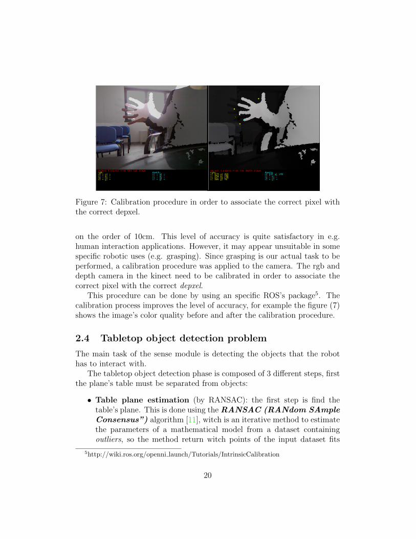
Figure 7: Calibration procedure in order to associate the correct pixel withthe correct depxel.
on the order of 10cm. This level of accuracy is quite satisfactory in e.g.human interaction applications. However, it may appear unsuitable in somespecific robotic uses (e.g. grasping). Since grasping is our actual task to beperformed, a calibration procedure was applied to the camera. The rgb anddepth camera in the kinect need to be calibrated in order to associate thecorrect pixel with the correct depxel.
This procedure can be done by using an specific ROS’s package5. Thecalibration process improves the level of accuracy, for example the figure (7)shows the image’s color quality before and after the calibration procedure.
2.4 Tabletop object detection problem
The main task of the sense module is detecting the objects that the robothas to interact with.
The tabletop object detection phase is composed of 3 different steps, firstthe plane’s table must be separated from objects:
• Table plane estimation (by RANSAC): the first step is find thetable’s plane. This is done using the RANSAC (RANdom SAmpleConsensus”) algorithm [11], witch is an iterative method to estimatethe parameters of a mathematical model from a dataset containingoutliers, so the method return witch points of the input dataset fits
5http://wiki.ros.org/openni launch/Tutorials/IntrinsicCalibration
20
a certain model (with some level of accuracy the algorithm is non-deterministic). In our case the input model to fit will be a plane, thetable’s plane. The points of the table are detected estimating first aplane in the point cloud, all the points which belong to such a planeare the points of the table.
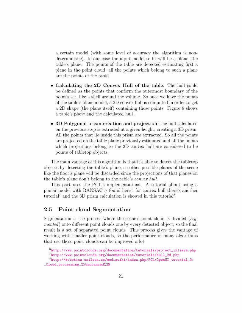
• Calculating the 2D Convex Hull of the table: The hull couldbe defined as the points that conform the outermost boundary of thepoint’s set, like a shell around the volume. So once we have the pointsof the table’s plane model, a 2D convex hull is computed in order to geta 2D shape (the plane itself) containing those points. Figure 8 showsa table’s plane and the calculated hull.
• 3D Polygonal prism creation and projection: the hull calculatedon the previous step is extruded at a given height, creating a 3D prism.All the points that lie inside this prism are extracted. So all the pointsare projected on the table plane previously estimated and all the pointswhich projections belong to the 2D convex hull are considered to bepoints of tabletop objects.
The main vantage of this algorithm is that it’s able to detect the tabletopobjects by detecting the table’s plane, so other possible planes of the scenelike the floor’s plane will be discarded since the projections of that planes onthe table’s plane don’t belong to the table’s convex hull.
This part uses the PCL’s implementations. A tutorial about using aplanar model with RANSAC is found here6, for convex hull there’s anothertutorial7 and the 3D prism calculation is showed in this tutorial8.
2.5 Point cloud Segmentation
Segmentation is the process where the scene’s point cloud is divided (seg-mented) onto different point clouds one by every detected object, so the finalresult is a set of separated point clouds. This process gives the vantage ofworking with smaller point clouds, so the performance of many algorithmsthat use these point clouds can be improved a lot.
6http://www.pointclouds.org/documentation/tutorials/project_inliers.php7http://www.pointclouds.org/documentation/tutorials/hull_2d.php8http://robotica.unileon.es/mediawiki/index.php/PCL/OpenNI_tutorial_3:
_Cloud_processing_%28advanced%29
21
(a) table’s point cloud.
(b) Calculated hull.
Figure 8: These figures show the tabletop’s point cloud and the calculatedhull.
22
So once the objects have been detected (using the previous section’s meth-ods), another phase must be performed: the point cloud segmentation phase.
2.5.1 The supervoxel concept
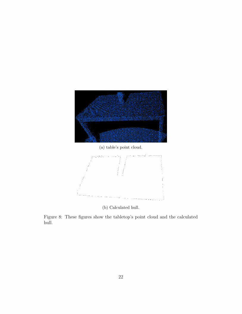
The principal goal is to deconstruct a scene into separate object parts withoutthe need for training or classification. As psycho-physical studies suggest, inhumans the lowest level decomposition of objects into parts is closely inter-twined with 3D concave/convex relationships. The VCCS (Voxel CloudConnectivy Segmentation) algorithm [15] used in this phase (an overviewof which is given in 9, the image was taken from this9 tutorial) tries to reliablyidentify regions of local convexity in point cloud data.
The VCCS algorithm over-segments 3D point cloud data into patches.These patches are called supervoxels. A supervoxel is a group of voxels thatshare similar properties. Supervoxels are the 3D analog of superpixels10.Using voxels is possible since modern RGB-D sensors provide the object’s3D geometry as output.
The VCCS algorithm is divided in the following phases:
1. Generation the labeling of points. This is done using a variant of k-means clustering. The result of this phase is a voxelized point cloud.
2. Adjacency Graph construction. Using the voxelized point cloud thegraph is constructed and is a key element for the segmentation.
3. Spatial Seeding. In this phase the algorithm selects some point cloud’spoints that will be used to initialize the supervoxels.
4. Features and Distance Measure. Supervoxels are clusters in a 39 di-mensional space. This vector is created using the spatial coordinates,the point’s color information and a 33-dimensional feature vector thatis obtained using the Fast Point Feature Histograms (FPFH)algorithm [22]. This a local geometry extractor method.
9http://pointclouds.org/documentation/tutorials/supervoxel_clustering.
php10Superpixel: A polygonal part of a digital image, larger than a normal pixel, that is
rendered in the same colour and brightness.
23
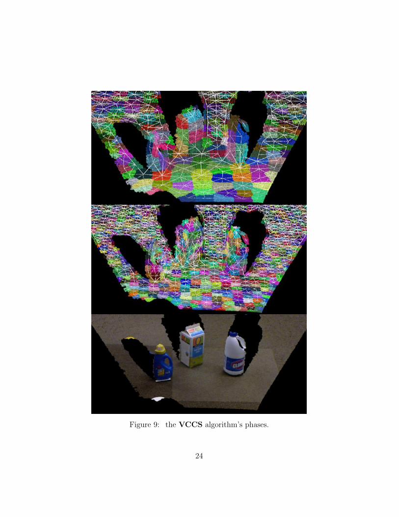
Figure 9: the VCCS algorithm’s phases.
24
5. Flow Constrained Clustering. The last phase assigns at every pointcloud’s voxel a supervoxel. This is done iteratively, using a local k-means clustering method.
The supervoxels method works directly on point clouds, which has advan-tages over other methods which operate with projected images. An impor-tant characteristic of this algorithm is the ability to segment clouds comingfrom many sensor observations i.e. using multiple cameras or accumulatedclouds from one. Computationally, this is advantageous, as the speed of thismethod is dependent on the number of occupied voxels in the scene, and notthe number of observed pixels. As observations will have significant overlap,this means that it is cheaper to segment the overall voxel cloud than theindividual 2D observations.
2.5.2 Segmentation algorithm
Using the supervoxels of the previous section there are a lot of interestingalgorithms to perform object’s segmentation. The Object Partitioningusing Local Convexity [7] is a good algorithm that can be found in thelast PCL’s release, the version 1.7.
There’s another state-of-art algorithm that can be found in the the notstable release of the PCL’S library, the 1.8. This is the Local ConvexConnected Patches Segmentation (LCCP) [7] that is a state-of-artalgorithm for segmentation using supervoxels as input.
2.5.3 LCCP algorithm
The Local Convex Connected Patches Segmentation (as other seg-mentation algorithms based on voxels) takes the assumption that objects areconvex . This true for many objects but not for all and is good to havepresent this condition on the experiment’s phase.
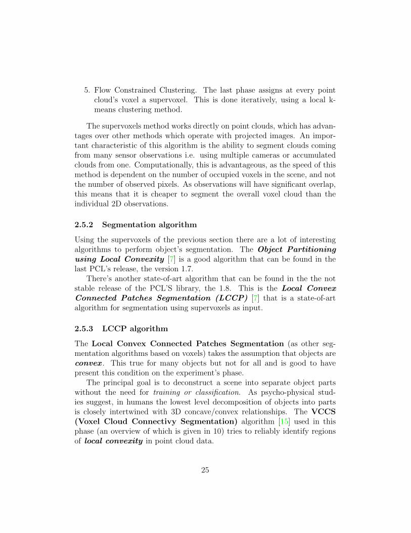
The principal goal is to deconstruct a scene into separate object partswithout the need for training or classification. As psycho-physical stud-ies suggest, in humans the lowest level decomposition of objects into partsis closely intertwined with 3D concave/convex relationships. The VCCS(Voxel Cloud Connectivy Segmentation) algorithm [15] used in thisphase (an overview of which is given in 10) tries to reliably identify regionsof local convexity in point cloud data.
25
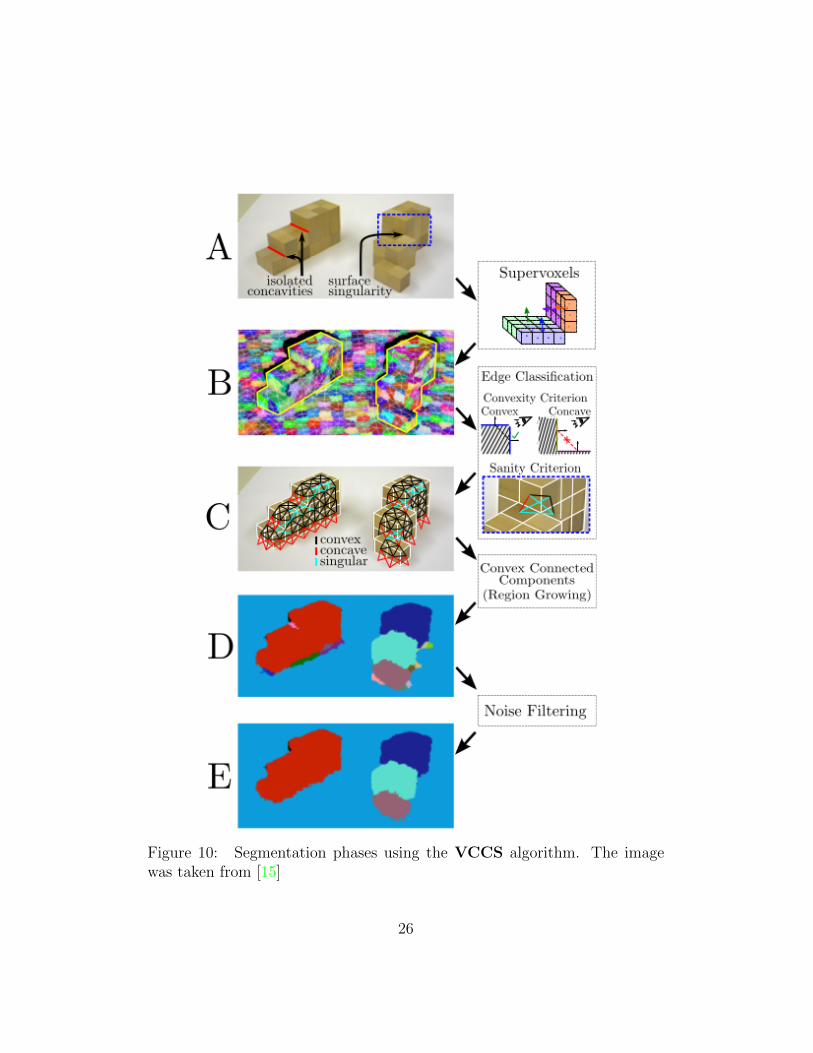
Figure 10: Segmentation phases using the VCCS algorithm. The imagewas taken from [15]
26
The VCCS algorithm over-segments 3D point cloud data into patches.These patches are called supervoxels. A supervoxel is a group of voxels thatshare similar properties. Supervoxels are the 3D analog of superpixels. Us-ing voxels is possible since modern RGB-D sensors provide the object’s 3Dgeometry as output.
The main algorithm’s phases are presented in the Figure 10.The VCCS algorithm gives a surface patch adjacency graph as output,
this supervoxel adjacency graph is segmented by classifying the connectionbetween two supervoxels is convex (valid) or concave (invalid). Two criteriaare used to classify this connection:
• Extended Convexity Criterion (CC) - uses the centroids of twoadjacent supervoxels, the connection between them (covex or concave)can be calculated by seeing the relation of the surface normals to thevector joining their centroids.
• Sanity criterion (SC) - takes the adjacent supervoxels that arepotentially convex and search for surface’s geometric discontinuities. Ifdiscontinuities are found, connections between these two supervoxelsare invalidated.
The PCL algorithm’s implementation is very good, so the segmentationphase is very fast (using a lowend 2 core duo Thinkpad with 4GB of RAM).
The algorithm also works very well when must segment cluttered scenes.The only problem is that there’s a minimum dimension threshold that theinput point cloud must have. If the point cloud is too small the algorithmcan’t see anything. So the algorithm presents problems for segmentingsmall objects.
For a detailed description of the algorithm’s parameters and installationdependencies see [19].
2.6 The sense module package implementation
The sense module was implemented as a ROS package (Figure 11). Thepackage has the following structure:
• sense metapackage: container of the sense module’s packages.
• sense segmentation package: contains the service that calls seg-mentation algorithm’s implementation.
27
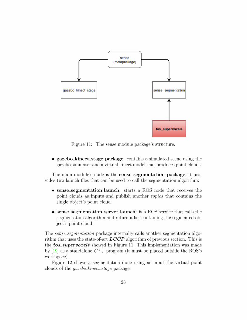
Figure 11: The sense module package’s structure.
• gazebo kinect stage package: contains a simulated scene using thegazebo simulator and a virtual kinect model that produces point clouds.
The main module’s node is the sense segmentation package, it pro-vides two launch files that can be used to call the segmentation algorithm:
• sense segmentation.launch: starts a ROS node that receives thepoint clouds as inputs and publish another topics that contains thesingle object’s point cloud.
• sense segmentation server.launch: is a ROS service that calls thesegmentation algorithm and return a list containing the segmented ob-ject’s point cloud.
The sense segmentation package internally calls another segmentation algo-rithm that uses the state-of-art LCCP algorithm of previous section. This isthe tos supervoxels showed in Figure 11. This implementation was madeby [19] as a standalone C++ program (it must be placed outside the ROS’sworkspace).
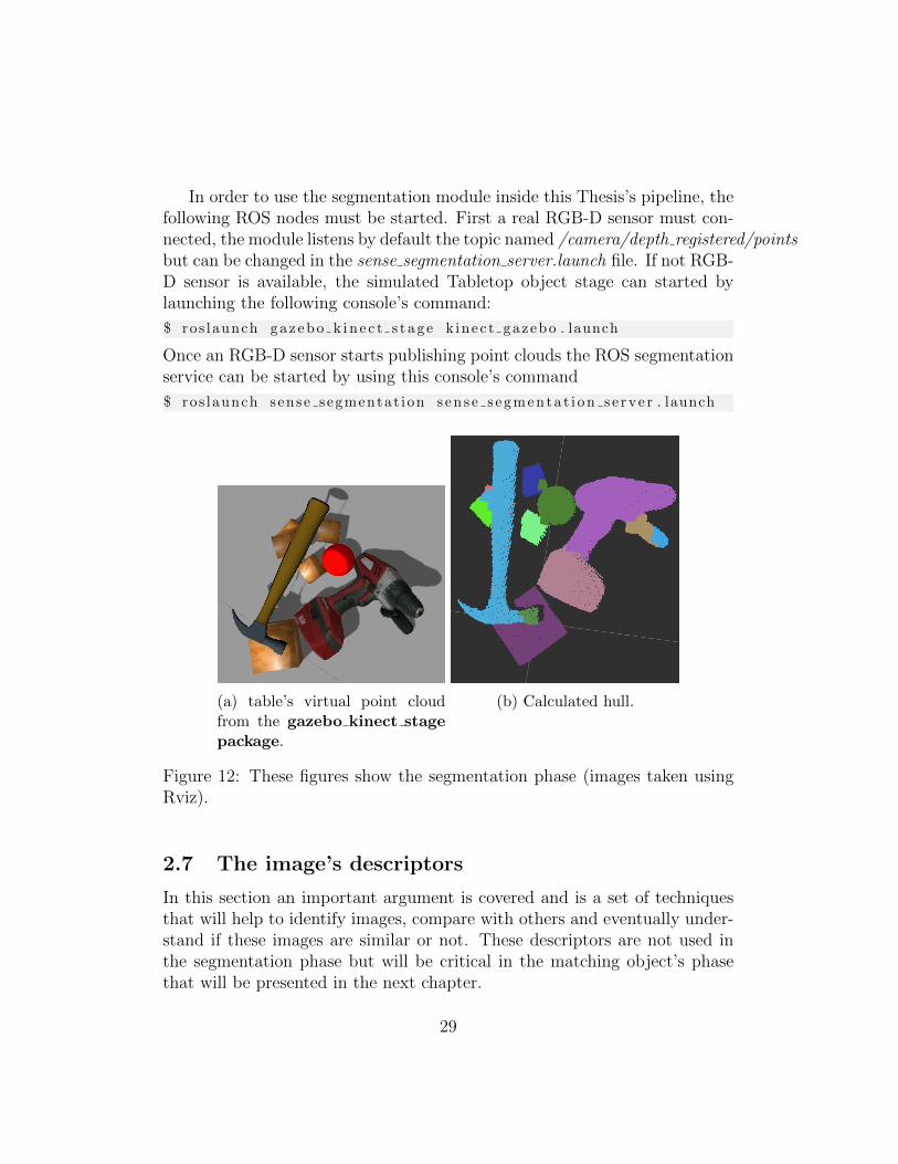
Figure 12 shows a segmentation done using as input the virtual pointclouds of the gazebo kinect stage package.
28
In order to use the segmentation module inside this Thesis’s pipeline, thefollowing ROS nodes must be started. First a real RGB-D sensor must con-nected, the module listens by default the topic named /camera/depth registered/pointsbut can be changed in the sense segmentation server.launch file. If not RGB-D sensor is available, the simulated Tabletop object stage can started bylaunching the following console’s command:
$ ros launch g a z e b o k i n e c t s t a g e k inec t gazebo . launch
Once an RGB-D sensor starts publishing point clouds the ROS segmentationservice can be started by using this console’s command
$ ros launch sense segmentat ion s e n s e s e g m e n t a t i o n s e r v e r . launch
(a) table’s virtual point cloudfrom the gazebo kinect stagepackage.
(b) Calculated hull.
Figure 12: These figures show the segmentation phase (images taken usingRviz).
2.7 The image’s descriptors
In this section an important argument is covered and is a set of techniquesthat will help to identify images, compare with others and eventually under-stand if these images are similar or not. These descriptors are not used inthe segmentation phase but will be critical in the matching object’s phasethat will be presented in the next chapter.
29
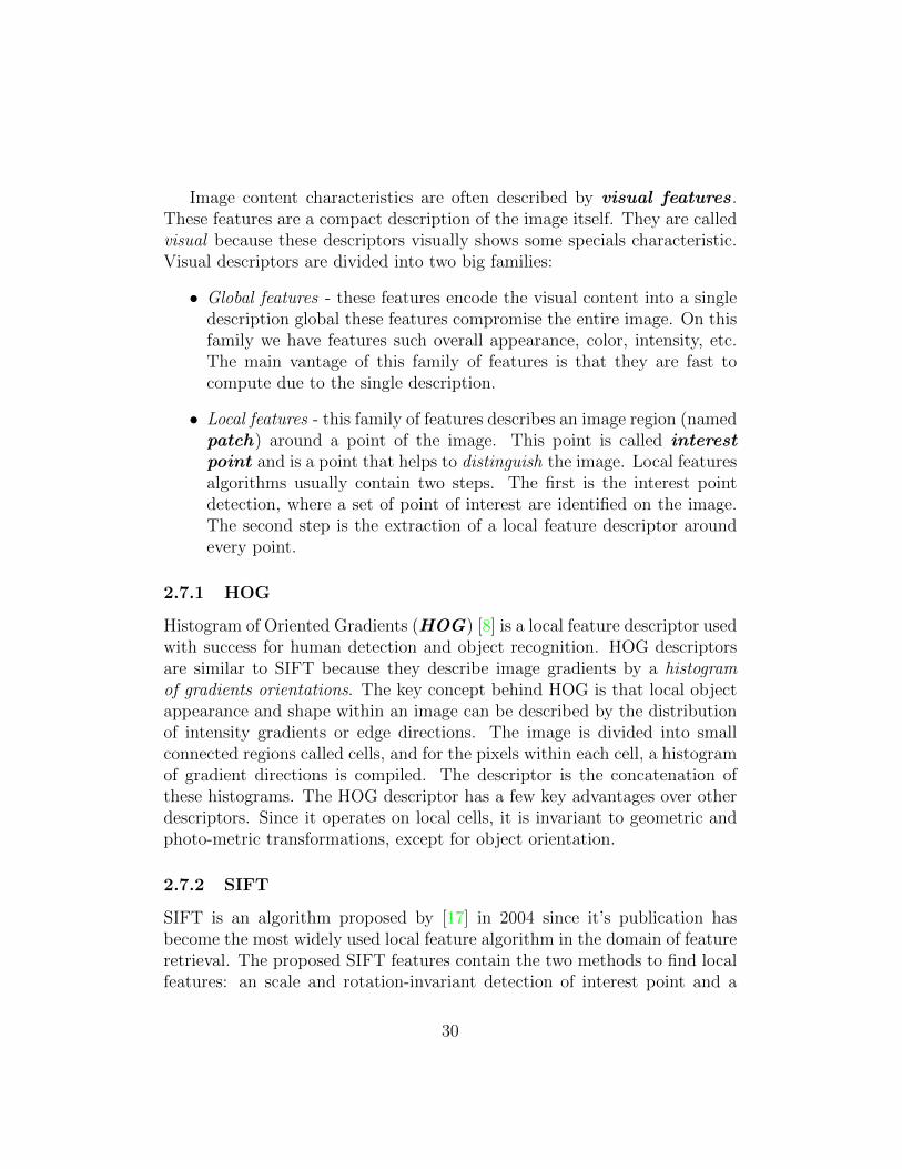
Image content characteristics are often described by visual features.These features are a compact description of the image itself. They are calledvisual because these descriptors visually shows some specials characteristic.Visual descriptors are divided into two big families:
• Global features - these features encode the visual content into a singledescription global these features compromise the entire image. On thisfamily we have features such overall appearance, color, intensity, etc.The main vantage of this family of features is that they are fast tocompute due to the single description.
• Local features - this family of features describes an image region (namedpatch) around a point of the image. This point is called interestpoint and is a point that helps to distinguish the image. Local featuresalgorithms usually contain two steps. The first is the interest pointdetection, where a set of point of interest are identified on the image.The second step is the extraction of a local feature descriptor aroundevery point.
2.7.1 HOG
Histogram of Oriented Gradients (HOG) [8] is a local feature descriptor usedwith success for human detection and object recognition. HOG descriptorsare similar to SIFT because they describe image gradients by a histogramof gradients orientations. The key concept behind HOG is that local objectappearance and shape within an image can be described by the distributionof intensity gradients or edge directions. The image is divided into smallconnected regions called cells, and for the pixels within each cell, a histogramof gradient directions is compiled. The descriptor is the concatenation ofthese histograms. The HOG descriptor has a few key advantages over otherdescriptors. Since it operates on local cells, it is invariant to geometric andphoto-metric transformations, except for object orientation.
2.7.2 SIFT
SIFT is an algorithm proposed by [17] in 2004 since it’s publication hasbecome the most widely used local feature algorithm in the domain of featureretrieval. The proposed SIFT features contain the two methods to find localfeatures: an scale and rotation-invariant detection of interest point and a
30
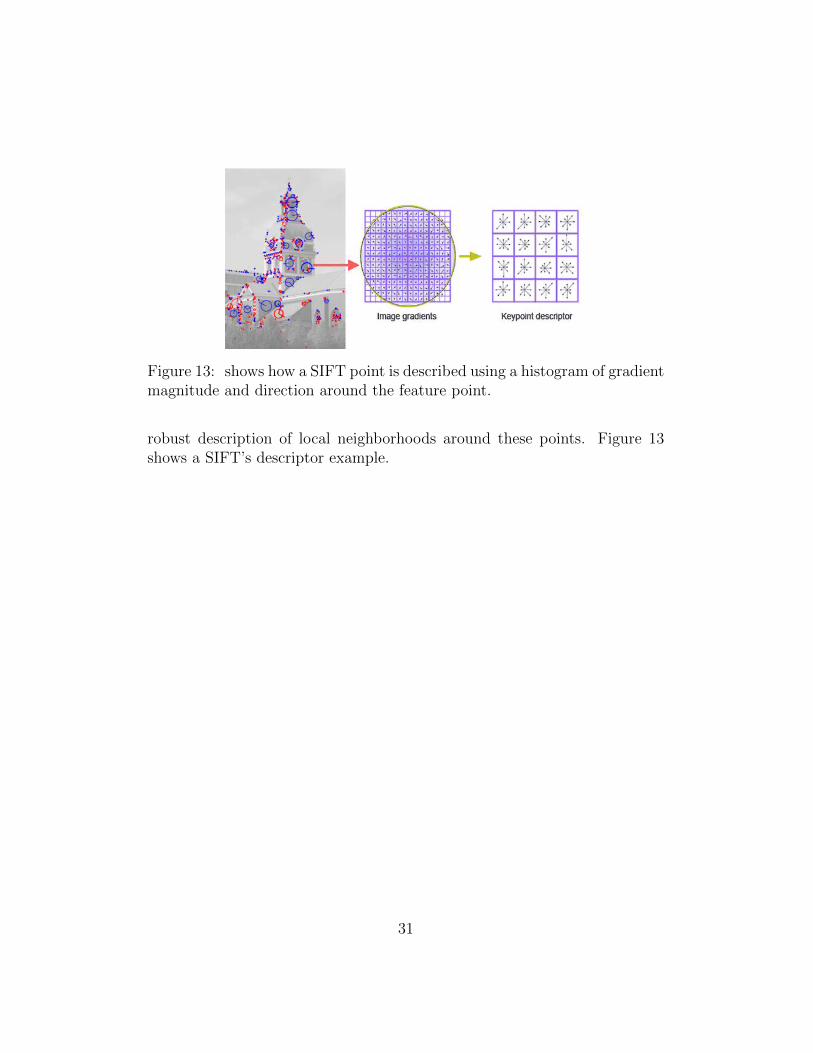
Figure 13: shows how a SIFT point is described using a histogram of gradientmagnitude and direction around the feature point.
robust description of local neighborhoods around these points. Figure 13shows a SIFT’s descriptor example.
31
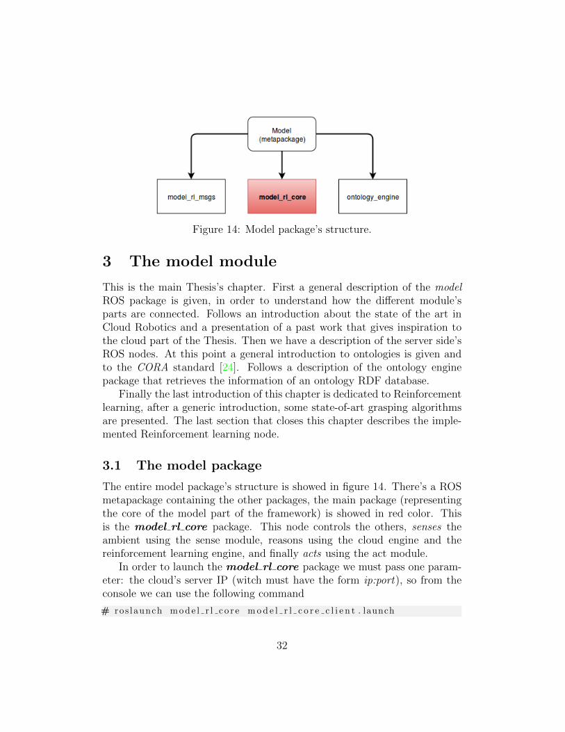
Figure 14: Model package’s structure.
3 The model module
This is the main Thesis’s chapter. First a general description of the modelROS package is given, in order to understand how the different module’sparts are connected. Follows an introduction about the state of the art inCloud Robotics and a presentation of a past work that gives inspiration tothe cloud part of the Thesis. Then we have a description of the server side’sROS nodes. At this point a general introduction to ontologies is given andto the CORA standard [24]. Follows a description of the ontology enginepackage that retrieves the information of an ontology RDF database.
Finally the last introduction of this chapter is dedicated to Reinforcementlearning, after a generic introduction, some state-of-art grasping algorithmsare presented. The last section that closes this chapter describes the imple-mented Reinforcement learning node.
3.1 The model package
The entire model package’s structure is showed in figure 14. There’s a ROSmetapackage containing the other packages, the main package (representingthe core of the model part of the framework) is showed in red color. Thisis the model rl core package. This node controls the others, senses theambient using the sense module, reasons using the cloud engine and thereinforcement learning engine, and finally acts using the act module.
In order to launch the model rl core package we must pass one param-eter: the cloud’s server IP (witch must have the form ip:port), so from theconsole we can use the following command
# ros launch m o d e l r l c o r e m o d e l r l c o r e c l i e n t . launch
32
s e r v e r i p a d d r :=CLOUD SERVER IP:9090
At the initialization phase, the node waits for a point cloud of the scene thatarrives from the RGB-D sensors, the topic’s name where the node waits forthe point cloud is /camera/depth registered/points but can be changedinside the file model rl core model rl core client.launch. When the new pointcloud arrives the node calls the sense segmentation service that returns a listwith the segmented object’s point clouds. At this point the object can begrasped by the robot but first this reasoning engine must understand how tograsp the object itself. The node finds the grasping by calling:
1. The cloud engine - searches the best object’s grasping.
2. The reinforcement learning engine - if not grasping if found by the cloudpart.
The following sections will explain these two engines. Before the engine’sdescription some arguments are introduced in order to facilitate the under-standing of the engines.
3.2 Cloud Robotics
The relationship between network and robots begins more than 30 years ago.Industrial robots began using primitive networks to be controlled from remotelocations. Since then and after the incredible development of Internet, robotsbegan using the same protocols, like the HTTP protocol, to communicatebetween them. Until a few years ago, communication between robots was notstandardized and/or engineered. There was not an standard that all robotscould use but only adHoc communications.
In 2010 James Kuffner coined the term Cloud Robotics to define thebranch of robotics related to robot’s communication using the modern cloudtechnologies. This new branch is also related to another popular branch ofcomputing, the Internet of things that describes how devices communicateand share information.
The Cloud can help robotics development in many ways, not only withcommunication between robots but also by extending hardware, softwareand cognitive possibilities of every single robot. Efforts are now focused ondeveloping the standard protocols and tools in order give an easy and fastaccess to remote resources to robots.
33
This survey [9] gives a complete introduction (also as a historic point ofview) to Cloud Robotics.
3.2.1 Related work and state-of-art developments
In the last years many works focused on standardizing robot’s cloud access.An popular work is RoboEarth [20]. A big project that provides standards toshare information between robots using the Internet infrastructure as chan-nel. The way that robots share information is very important because knowl-edge must be managed in a certain way in order to optimize sharing and usingwith robots. On the RoboEarth platform knowledge is represented by usingan Ontology (see the next section for further details about ontologies) butthe problem is that it’s not an standard ontology. Anyway the main problemwith RoboEarth is that the system has not an scalable recognition pipeline.
Another interesting state-of-art work is CORE [27]. It proposes a com-plete object’s recognition pipeline but using a distributed and scalable ar-chitecture. The best part of this work is the distributed architecture thatintroduces modern web application standards like JSON and websockets ona Cloud Robotics Architecture. The creators payed particular attention tooptimize transmission of large amounts of data. In particular the gener-ated point clouds are compressed (using the method described in [14]) beforetransmission and the compressed point clouds are only send to server onlyif the scene’s variation is over a fixed threshold. This techniche is knownas point cloud culling . Using this method [5] point clouds are selectivelyculled prior to transmission to the cloud. Culling is performed by measuringthe scene entropy of sequential point cloud frames.
On the other side this work has some characteristics that are not wellsuited for this Thesis’s objectives: the recognition engine needs a separatedtraining phase to work correctly since learning it’s based on a SupportVector Machine (SVM). Finally as authors points out the work could beextended to develop a complete service oriented architecture.
3.2.2 Introduction to ontologies
On the machine learning domain there are many definitions of an ontology;some of these contradict one another. A common definition follows: anontology is a formal explicit description of concepts in a domain of discourse(classes (also called concepts)), properties of each concept describing various
34
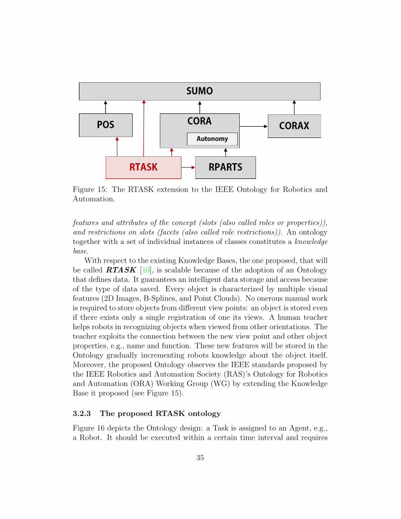
Figure 15: The RTASK extension to the IEEE Ontology for Robotics andAutomation.
features and attributes of the concept (slots (also called roles or properties)),and restrictions on slots (facets (also called role restrictions)). An ontologytogether with a set of individual instances of classes constitutes a knowledgebase.
With respect to the existing Knowledge Bases, the one proposed, that willbe called RTASK [10], is scalable because of the adoption of an Ontologythat defines data. It guarantees an intelligent data storage and access becauseof the type of data saved. Every object is characterized by multiple visualfeatures (2D Images, B-Splines, and Point Clouds). No onerous manual workis required to store objects from different view points: an object is stored evenif there exists only a single registration of one its views. A human teacherhelps robots in recognizing objects when viewed from other orientations. Theteacher exploits the connection between the new view point and other objectproperties, e.g., name and function. These new features will be stored in theOntology gradually incrementing robots knowledge about the object itself.Moreover, the proposed Ontology observes the IEEE standards proposed bythe IEEE Robotics and Automation Society (RAS)’s Ontology for Roboticsand Automation (ORA) Working Group (WG) by extending the KnowledgeBase it proposed (see Figure 15).
3.2.3 The proposed RTASK ontology
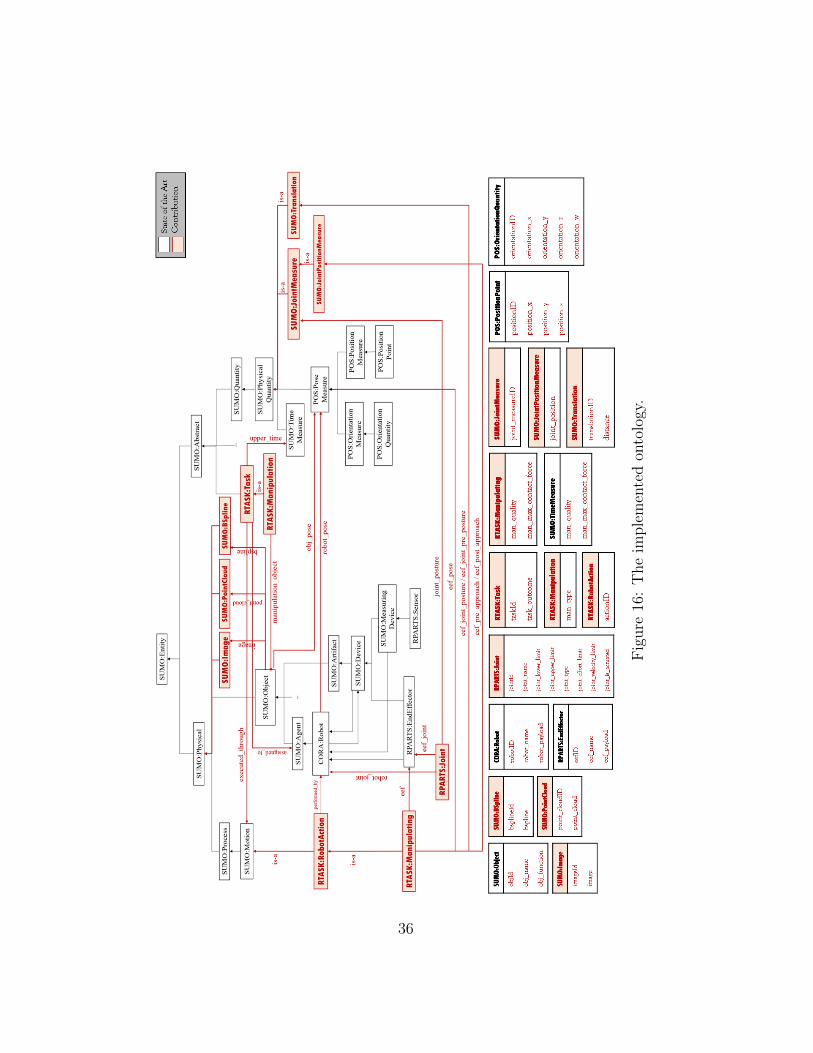
Figure 16 depicts the Ontology design: a Task is assigned to an Agent, e.g.,a Robot. It should be executed within a certain time interval and requires
35
Fig
ure
16:
The
imple
men
ted
onto
logy
.
36
the fulfillment of a certain Motion in order to be performed. Manipulationis a sub-class of Task. Several types of manipulations exist, e.g., grasps andpushes.
They involve the handling of an Object located at a certain Pose (Positionand Orientation) through the execution of a Manipulating action. If theTask is assigned to a Robot, then the Motion will be represented by a RobotAction. In detail, the Robot Manipulation Action involves the activation ofthe robot End Effector.
In order to retrieve the manipulation data of an object in the scene, theobject should be recognized as an instance previously stored in the Ontology.For this purpose, every Object is characterized by an id, name, function, andthe visual features obtained by the Sensors. For every Object, RTASK storesmultiple types of visual features: 2D Images, B-Splines, and (compressed)Point Clouds.
3.2.4 The implemented Cloud-based Engine
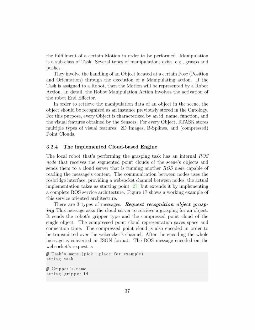
The local robot that’s performing the grasping task has an internal ROSnode that receives the segmented point clouds of the scene’s objects andsends them to a cloud server that is running another ROS node capable ofreading the message’s content. The communication between nodes uses therosbridge interface, providing a websocket channel between nodes, the actualimplementation takes as starting point [27] but extends it by implementinga complete ROS service architecture. Figure 17 shows a working example ofthis service oriented architecture.
There are 3 types of messages: Request recognition object grasp-ing This message asks the cloud server to retrieve a grasping for an object.It sends the robot’s gripper type and the compressed point cloud of thesingle object. The compressed point cloud representation saves space andconnection time. The compressed point cloud is also encoded in order tobe transmitted over the websocket’s channel. After the encoding the wholemessage is converted in JSON format. The ROS message encoded on thewebsocket’s request is
# Task ’ s name ( pick , p lace f o r example )s t r i n g task
# Gripper ’ s names t r i n g g r i p p e r i d
37
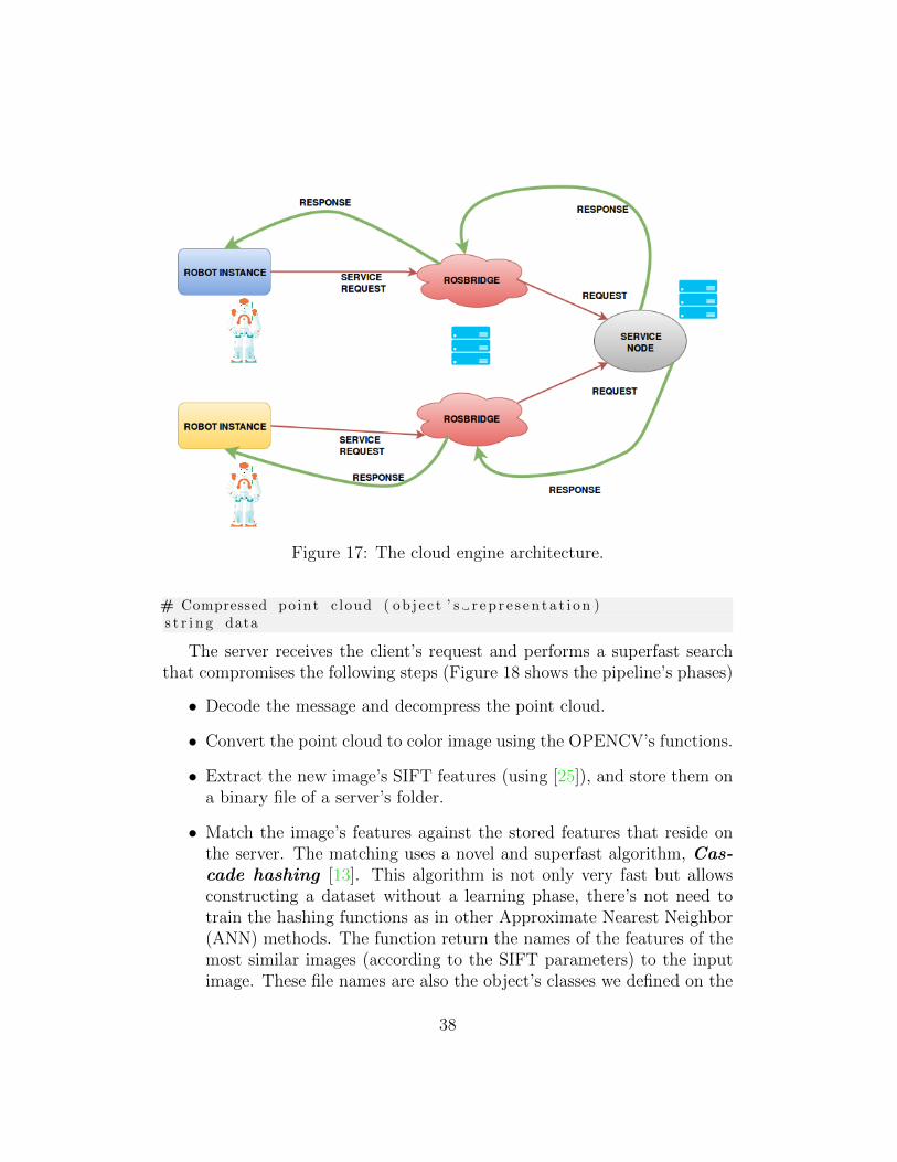
Figure 17: The cloud engine architecture.
# Compressed po int c loud ( ob j e c t ’ s r e p r e s e n t a t i o n )s t r i n g data
The server receives the client’s request and performs a superfast searchthat compromises the following steps (Figure 18 shows the pipeline’s phases)
• Decode the message and decompress the point cloud.
• Convert the point cloud to color image using the OPENCV’s functions.
• Extract the new image’s SIFT features (using [25]), and store them ona binary file of a server’s folder.
• Match the image’s features against the stored features that reside onthe server. The matching uses a novel and superfast algorithm, Cas-cade hashing [13]. This algorithm is not only very fast but allowsconstructing a dataset without a learning phase, there’s not need totrain the hashing functions as in other Approximate Nearest Neighbor(ANN) methods. The function return the names of the features of themost similar images (according to the SIFT parameters) to the inputimage. These file names are also the object’s classes we defined on the
38
Figure 18: The pipeline for fast image retrieval.
ontology database. So using only one sparql query with the classes asfilters we reduce the seek time inside the ontology, filtering only theclasses of the most similar objects.
• finally the sparql query returns the grasping information.
The similar object’s searching is very fast not only because we use the cascadehashing algorithm but also because the features of the stored objects arealready precalculated and stored on a server folder (they aren’t downloadevery time from the database). Along with this, using the feature’s name(an integer, like 1,2,3) as object class we avoid to perform many queries onthe ontology, performing only one query at the end of the matching process.
The server (using the websocket interface) encodes the following ROSmessage that contains the matched grasping information:
s t r i n g t a s k r e s p o n s e
s t r i n g t a s k i d
# The i n t e r n a l posture o f the hand for the pre−grasp# only p o s i t i o n s are usedt r a j e c t o r y m s g s / Jo in tTra j e c to ry p r e g r a s p p o s t u r e
39
# The i n t e r n a l posture o f the hand for the grasp# p o s i t i o n s and e f f o r t s are usedt r a j e c t o r y m s g s / Jo in tTra j e c to ry g ra sp pos tu r e
# The p o s i t i o n o f the end−e f f e c t o r for the grasp .# This i s the pose o f# the ” p a r e n t l i n k ” o f the end−e f f e c t o r , not a c t u a l l y the# pose o f any l i n k ∗ in ∗ the end−e f f e c t o r .# Typica l l y this would be the pose o f the# most d i s t a l wr i s t l i n k be f o r e# the hand ( end−e f f e c t o r ) l i n k s began .
geometry msgs /PoseStamped grasp pose
# The approach d i r e c t i o n to take# be f o r e p i ck ing an ob j e c tmoveit msgs / Gr ipperTrans lat ion pre grasp approach
# The r e t r e a t d i r e c t i o n to take a f t e r# a grasp has been completed ( ob j e c t i s attached )moveit msgs / Gr ipperTrans lat ion p o s t g r a s p r e t r e a t
On the client’s side the grasping information is used by the act moduleto perform the grasping action, if the robot success grasping the object,finish the action. In other case, it comes to play the Reinforcement learningalgorithm. First given the point cloud some grasping positions are generatedusing the geometry’s gripper. These positions are then validated by thetrial/error process that resides insides the Reinforcement learning algorithm.If a grasping action is successfully executed, an human operator validates theresult. With this information the client creates another message:
{ ”op” : ” send new object ” ,” s e r v i c e ” : ” i n s e r t ” ,” new object ” :
[{” new point c loud ” : ”zc5p81H1cO8P+Ksmfdf . . . ” ,”X” : ” 0 .5 ” , ”Y” : ” 2 .5 ” , ”Z” : ” 1 .5 ” , ” rad” : ” 0 .314 ” } ,]}
Finally the server receives the message, calculates the object’s SIFT featuresand inserts them on the feature’s folder and on the ontology.
The last type of message is used for human robot interaction.
40
# Operation types t r i n g operat i on
# Object class ’ s names t r i n g c l a s s d e s c r i p t i o n
# Compressed po int c loud ( ob j e c t ’ s r e p r e s e n t a t i o n )s t r i n g data
In this case the human operator shows an object to the robot and gives anobject’s description (like coke can, pen), then the server non only seeks fora similar object but filters the ontology using the object’s description.
The local node sends the following information to the server using thejson standard as in [27] :
{ ”op” : ” s e a r c h o b j e c t ” ,” s e r v i c e ” : ” s end po in t c l oud ”” args ” : ”zc5p81H1cO8P+Ksmfdf . . . ” }
The args part in the above message is the compressed point cloud. The servertakes the point cloud, gets the SIFT features and search a similar objectusing the cascade hashing algorithm that uses a server’s directory containingall the object’s features in text format. If a match is found, the algorithmtakes the unique ID’s of the matched objects and performs an RDF query inorder to retrieve the object’s grasping information inside the ontology. Thenthe server returns the following message to the client:
{” s i m i l a r o b j e c t s ” :[{ ” c l a s s ” : ”1” , ”X” : ” 0 .5 ” , ”Y” : ” 2 .5 ” , ”Z” : ” 1 .5 ” , ” rad” : ” 0 .314 ” } ,{ ” c l a s s ” : ”2” , ”X” : ” 0 .1 ” , ”Y” : ” 24 .5 ” , ”Z” : ” 1 .3 ” , ” rad” : ” 0 .24 ” } ,{ ” c l a s s ” : ”3” , ”X” : ” 0 .2 ” , ”Y” : ” 3 .5 ” , ”Z” : ” 0 .5 ” , ” rad” : ” 2 .14 ” }
]}
If no similar objects are found, the response will be
{ ”op” : ” s e a r c h o b j e c t r e s p o n s e ” ,” s e r v i c e ” : ” query ” ,” s i m i l a r o b j e c t s ” :
[
]}
And on the client’s side comes to play the Reinforcement learning algorithm.First given the point cloud some grasping positions are generated using the
41
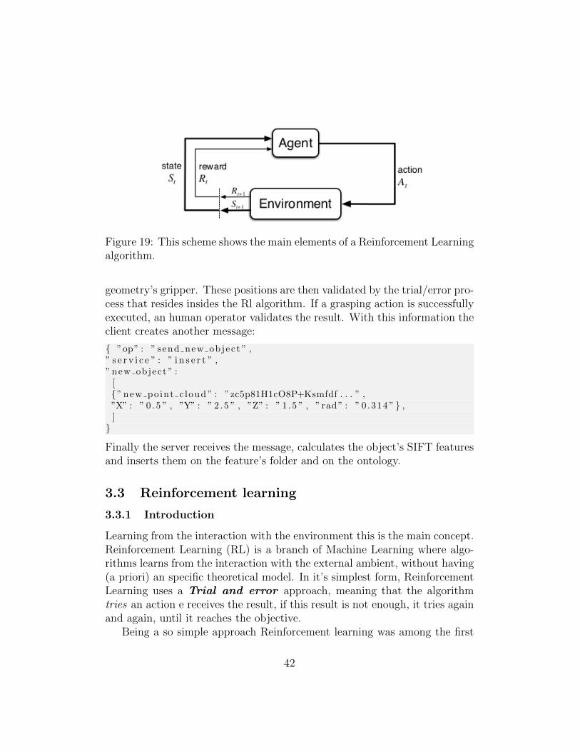
Figure 19: This scheme shows the main elements of a Reinforcement Learningalgorithm.
geometry’s gripper. These positions are then validated by the trial/error pro-cess that resides insides the Rl algorithm. If a grasping action is successfullyexecuted, an human operator validates the result. With this information theclient creates another message:
{ ”op” : ” send new object ” ,” s e r v i c e ” : ” i n s e r t ” ,” new object ” :
[{” new point c loud ” : ”zc5p81H1cO8P+Ksmfdf . . . ” ,”X” : ” 0 .5 ” , ”Y” : ” 2 .5 ” , ”Z” : ” 1 .5 ” , ” rad” : ” 0 .314 ” } ,]}
Finally the server receives the message, calculates the object’s SIFT featuresand inserts them on the feature’s folder and on the ontology.
3.3 Reinforcement learning
3.3.1 Introduction
Learning from the interaction with the environment this is the main concept.Reinforcement Learning (RL) is a branch of Machine Learning where algo-rithms learns from the interaction with the external ambient, without having(a priori) an specific theoretical model. In it’s simplest form, ReinforcementLearning uses a Trial and error approach, meaning that the algorithmtries an action e receives the result, if this result is not enough, it tries againand again, until it reaches the objective.
Being a so simple approach Reinforcement learning was among the first
42
branch of Machine learning to be studied in the sixties and in the seventies,but since the results were not so brilliant, scientists decided to move toanother Machine learning’s branch.
A must read introduction to Reinforcement Learning is the Sutton andBarto’s book ([23]), the online version of the last edition can be downloadedfor free.
The main elements that are always present on a RL algorithm are
• Agent: This element learns from the interaction with the environment.Uses actions to interact with the environment and has at least oneobjective to reach.
• Environment: this element is sometimes seen as the external world tothe robot. Has internal states that changes in function to the agent’sactions.
There are another important elements conforming an RL algorithm:
• Action: the activity that performs the agent in order to interact withthe environment. It can change the environment’s state.
• State: The set of internal states that the environment can adopt.
• Sensation: the ability that has the agent to sense in witch state theenvironment is and taking account of this to select the best action.
• Goal: the objective that the agent has to reach when it interacts withthe environment.
The last 3 elements that are common in a RL algorithms are:
• Policy: the way in witch the agent must act in an specific time. It’s amap that connects the environment’s states with the agent’s actions.
• Reward signal: the objective that agent has to reach is measured bythis signal, typically a real value. This signal is produced by the inter-action with the environment. The agent must maximize or minimize(depending on the problem) this signal over the time.
• Value function: The previous Reward signal offers an evaluation on theshort term, on the long term the Value function tries to optimize thereward at a global level.
43
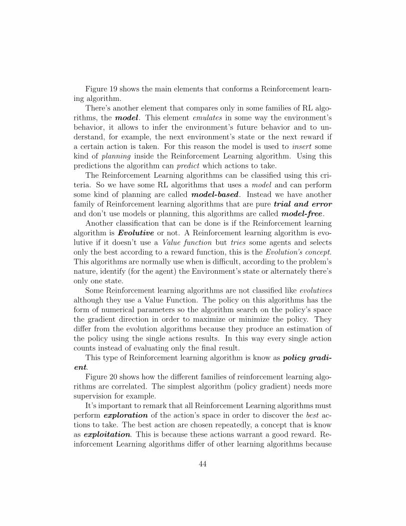
Figure 19 shows the main elements that conforms a Reinforcement learn-ing algorithm.
There’s another element that compares only in some families of RL algo-rithms, the model . This element emulates in some way the environment’sbehavior, it allows to infer the environment’s future behavior and to un-derstand, for example, the next environment’s state or the next reward ifa certain action is taken. For this reason the model is used to insert somekind of planning inside the Reinforcement Learning algorithm. Using thispredictions the algorithm can predict which actions to take.
The Reinforcement Learning algorithms can be classified using this cri-teria. So we have some RL algorithms that uses a model and can performsome kind of planning are called model-based . Instead we have anotherfamily of Reinforcement learning algorithms that are pure trial and errorand don’t use models or planning, this algorithms are called model-free .
Another classification that can be done is if the Reinforcement learningalgorithm is Evolutive or not. A Reinforcement learning algorithm is evo-lutive if it doesn’t use a Value function but tries some agents and selectsonly the best according to a reward function, this is the Evolution’s concept.This algorithms are normally use when is difficult, according to the problem’snature, identify (for the agent) the Environment’s state or alternately there’sonly one state.
Some Reinforcement learning algorithms are not classified like evolutivesalthough they use a Value Function. The policy on this algorithms has theform of numerical parameters so the algorithm search on the policy’s spacethe gradient direction in order to maximize or minimize the policy. Theydiffer from the evolution algorithms because they produce an estimation ofthe policy using the single actions results. In this way every single actioncounts instead of evaluating only the final result.
This type of Reinforcement learning algorithm is know as policy gradi-ent.
Figure 20 shows how the different families of reinforcement learning algo-rithms are correlated. The simplest algorithm (policy gradient) needs moresupervision for example.
It’s important to remark that all Reinforcement Learning algorithms mustperform exploration of the action’s space in order to discover the best ac-tions to take. The best action are chosen repeatedly, a concept that is knowas exploitation. This is because these actions warrant a good reward. Re-inforcement Learning algorithms differ of other learning algorithms because
44
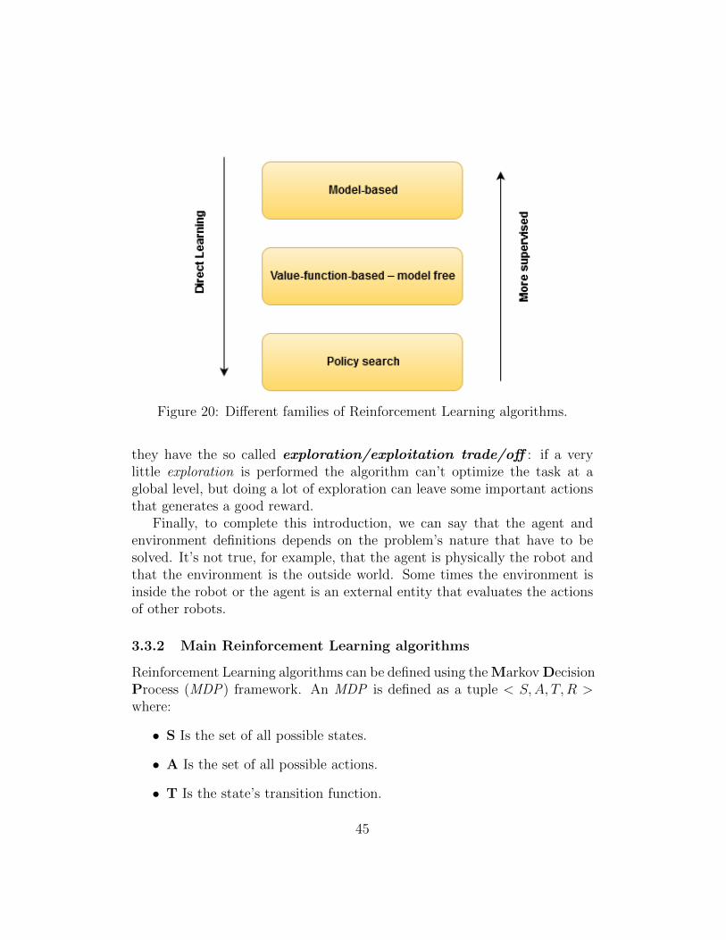
Figure 20: Different families of Reinforcement Learning algorithms.
they have the so called exploration/exploitation trade/off : if a verylittle exploration is performed the algorithm can’t optimize the task at aglobal level, but doing a lot of exploration can leave some important actionsthat generates a good reward.
Finally, to complete this introduction, we can say that the agent andenvironment definitions depends on the problem’s nature that have to besolved. It’s not true, for example, that the agent is physically the robot andthat the environment is the outside world. Some times the environment isinside the robot or the agent is an external entity that evaluates the actionsof other robots.
3.3.2 Main Reinforcement Learning algorithms
Reinforcement Learning algorithms can be defined using the Markov DecisionProcess (MDP) framework. An MDP is defined as a tuple < S,A, T,R >where:
• S Is the set of all possible states.
• A Is the set of all possible actions.
• T Is the state’s transition function.
45
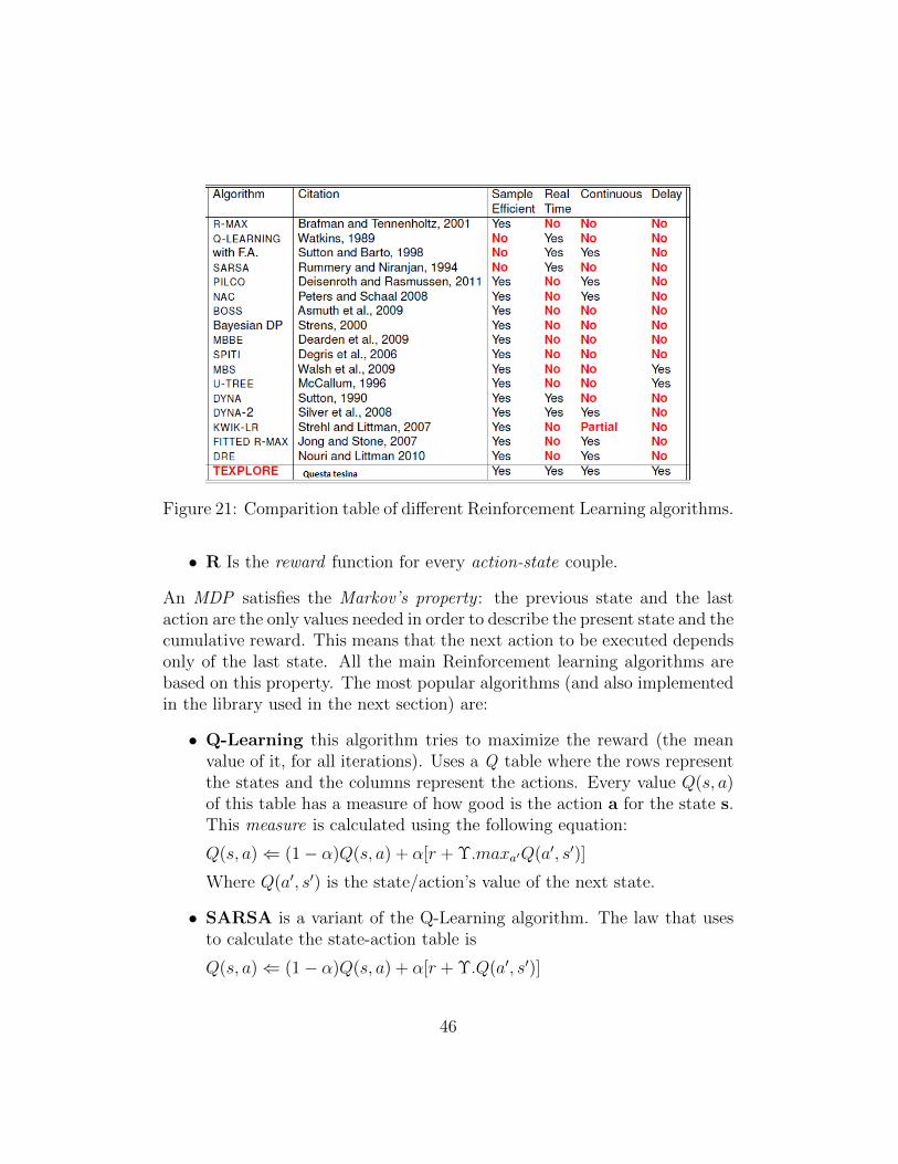
Figure 21: Comparition table of different Reinforcement Learning algorithms.
• R Is the reward function for every action-state couple.
An MDP satisfies the Markov’s property : the previous state and the lastaction are the only values needed in order to describe the present state and thecumulative reward. This means that the next action to be executed dependsonly of the last state. All the main Reinforcement learning algorithms arebased on this property. The most popular algorithms (and also implementedin the library used in the next section) are:
• Q-Learning this algorithm tries to maximize the reward (the meanvalue of it, for all iterations). Uses a Q table where the rows representthe states and the columns represent the actions. Every value Q(s, a)of this table has a measure of how good is the action a for the state s.This measure is calculated using the following equation:
Q(s, a)⇐ (1− α)Q(s, a) + α[r + Υ.maxa′Q(a′, s′)]
Where Q(a′, s′) is the state/action’s value of the next state.
• SARSA is a variant of the Q-Learning algorithm. The law that usesto calculate the state-action table is
Q(s, a)⇐ (1− α)Q(s, a) + α[r + Υ.Q(a′, s′)]
46
the difference with Q-learning is that the right member of the equationdoesn’t uses the max function and is used only the next state-action.This changes gives the algorithm a fast conversion to the optimal policyon certain conditions.
• RMAX this a model-based algorithm. It’s very simple as implementa-tion and allows to find an optimal reward’s value (at least as mean) inpolynomial time. The agent builds an environment’s complete model(not always accurate) and works on the calculated model’s policy inorder to handle (with an internal mechanism) the exploration vs ex-ploitation’s dilemma.
• Dyna as other algorithms it builds a similar table to that of the Q-learning algorithm for the state-action pairs. The difference is thatthis algorithm introduces planing. Planing means that Reinforcementlearning is applied to simulated model’s experiences and this experi-ences are combined with that obtained from the real environment.
• TEXPLORE ([26]) this is another model-based algorithm that learnsan specific environment’s model called Random Forest. The agent ex-plores all the states that seems promising in order to build the finalpolicy, ignoring the non promising states. Internally, this algorithmuses a parallel architecture that allows real time action selection. Forthis the algorithm is particularly useful to solve real-time problems likeautonomous vehicle driving.
Figure 21 shows a comparison between the different types of RL algo-rithms. As we can see the most complete algorithm in that table is theTEXPLORE algorithm and this is the Reinforcement learning algorithmthat will be used in the next section.
For a proper Reinforcement learning introduction the best source is theSutton’s book [23].
3.3.3 Related works - learning and grasping
The grasping pose generation problem of unknown objects is still an openproblem on Robotics. In the last two years were published interesting worksthat deal with the grasping problem using learning algorithms.
47
The first work is Supersizing Self-supervision: Learning to Grasp from50K Tries and 700 Robot Hours [21], where deep learning and neural net-works are used to solve the grasping problem of household objects. Theinteresting part of this work is how the grasping action itself is modeled. Itmodels a grasping action as a planar grasp. A planar grasp is one where thegrasp configuration is along and perpendicular to the workspace. Hence thegrasp configuration lies in 3 dimensions, (X, Y ): position of grasp point onthe surface of table and (θ) angle of grasp.
The second work is [3]. In this work a Reinforcement learning frame-work is proposed to solve the grasping of objects in a clutter problem. Theinteresting part of this work is that the grasping problem is modeled as aReinforcement learning problem. It also uses the planar grasp definition.
The last work reviewed is the Antipodal Grasping Identification and LEarn-ing (AGILE) [6]. This algorithm detects grasps directly from point clouds.Grasping detection is performed using geometrical features of the point cloud.The algorithm search for antipodal points inside the point cloud so the calcu-lated grasping pose is referred to that antipodal point. The only assumptionis that the gripper is a simple two fingers gripper. The algorithm outputs alots of antipodal points, so to reduce the candidate’s list a second phase witha machine learning algorithm (SVM) was implemented. Another interestingcharacteristic of this work is that it works with 1 or 2 RGB-D sensors asinput in order to improve the object’s point cloud quality.
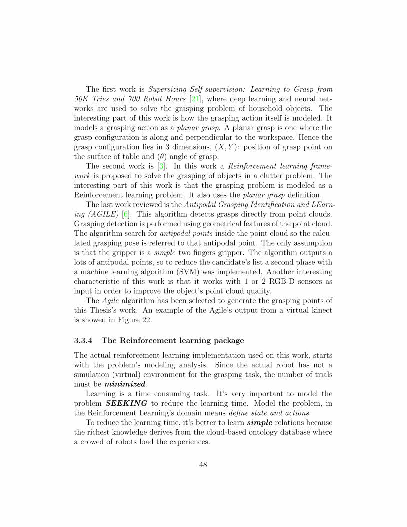
The Agile algorithm has been selected to generate the grasping points ofthis Thesis’s work. An example of the Agile’s output from a virtual kinectis showed in Figure 22.
3.3.4 The Reinforcement learning package
The actual reinforcement learning implementation used on this work, startswith the problem’s modeling analysis. Since the actual robot has not asimulation (virtual) environment for the grasping task, the number of trialsmust be minimized .
Learning is a time consuming task. It’s very important to model theproblem SEEKING to reduce the learning time. Model the problem, inthe Reinforcement Learning’s domain means define state and actions.
To reduce the learning time, it’s better to learn simple relations becausethe richest knowledge derives from the cloud-based ontology database wherea crowed of robots load the experiences.
48
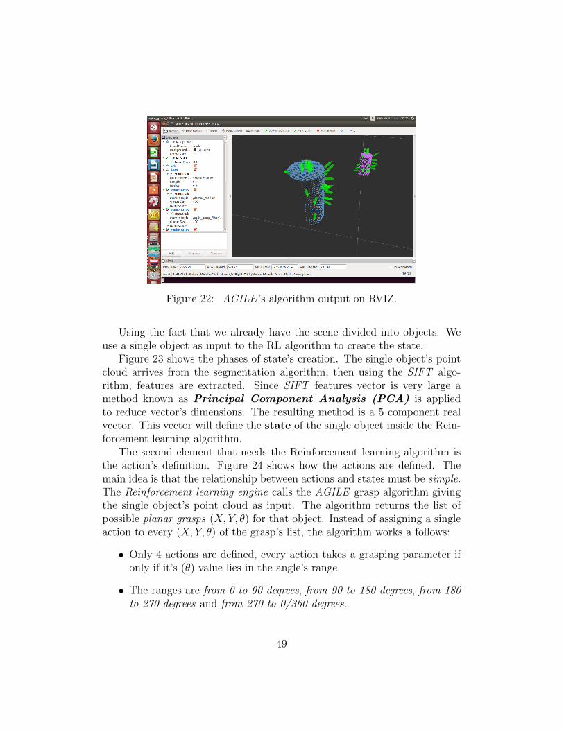
Figure 22: AGILE ’s algorithm output on RVIZ.
Using the fact that we already have the scene divided into objects. Weuse a single object as input to the RL algorithm to create the state.
Figure 23 shows the phases of state’s creation. The single object’s pointcloud arrives from the segmentation algorithm, then using the SIFT algo-rithm, features are extracted. Since SIFT features vector is very large amethod known as Principal Component Analysis (PCA) is appliedto reduce vector’s dimensions. The resulting method is a 5 component realvector. This vector will define the state of the single object inside the Rein-forcement learning algorithm.
The second element that needs the Reinforcement learning algorithm isthe action’s definition. Figure 24 shows how the actions are defined. Themain idea is that the relationship between actions and states must be simple.The Reinforcement learning engine calls the AGILE grasp algorithm givingthe single object’s point cloud as input. The algorithm returns the list ofpossible planar grasps (X, Y, θ) for that object. Instead of assigning a singleaction to every (X, Y, θ) of the grasp’s list, the algorithm works a follows:
• Only 4 actions are defined, every action takes a grasping parameter ifonly if it’s (θ) value lies in the angle’s range.
• The ranges are from 0 to 90 degrees, from 90 to 180 degrees, from 180to 270 degrees and from 270 to 0/360 degrees.
49
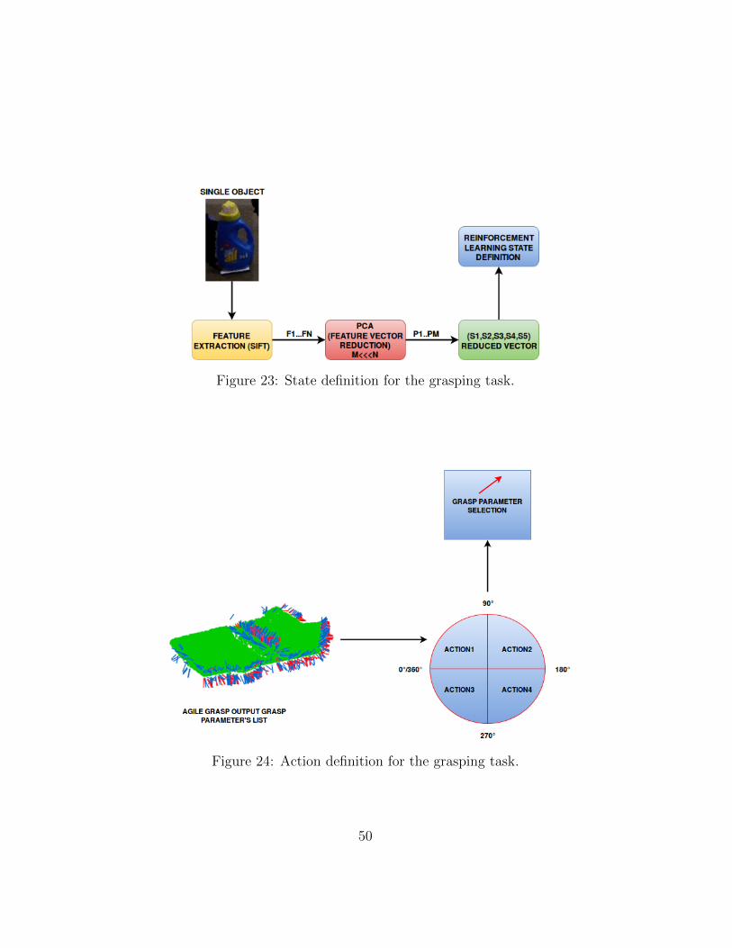
Figure 23: State definition for the grasping task.
Figure 24: Action definition for the grasping task.
50
The expected result is that the algorithm will choose the action (theplanar grasp) that has a high probability to be successful.
Once the (X, Y, θ) parameters are selected, the RL engine calls the Actmodule that executes the action on the robot.
The feedback if the grasp was done correctly is given by a human operator.The RL engine waits for the feedback in order to understand if continuing tograsp the object selecting another action or finishing if the grasping actionends successfully.
Inside the implemented ROS node, the class that manage Reinforcementlearning’s states and actions is the ModelRlGrasping.cpp that calls theReinforcement learning’s environment for the grasping task (another classinside the ROS’s rl-texplore-ros-pkg package). For the agent element, theTEXPLORE algorithm is used (the implementation is inside the rl-texplore-ros-pkg package) .
51
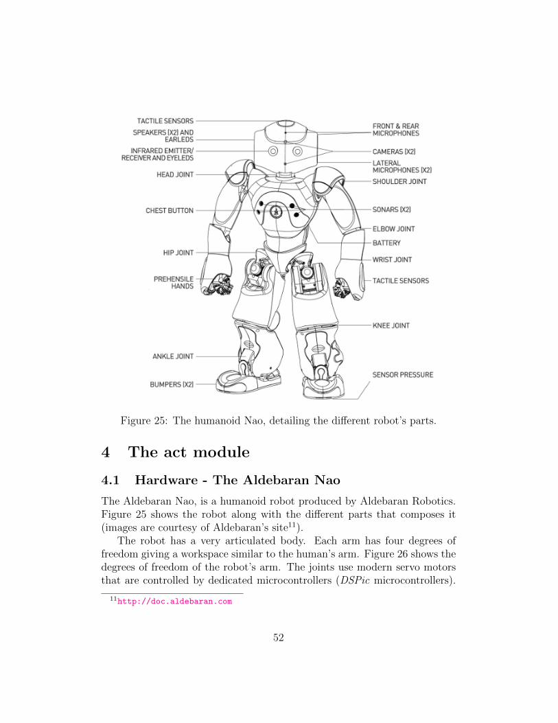
Figure 25: The humanoid Nao, detailing the different robot’s parts.
4 The act module
4.1 Hardware - The Aldebaran Nao
The Aldebaran Nao, is a humanoid robot produced by Aldebaran Robotics.Figure 25 shows the robot along with the different parts that composes it(images are courtesy of Aldebaran’s site11).
The robot has a very articulated body. Each arm has four degrees offreedom giving a workspace similar to the human’s arm. Figure 26 shows thedegrees of freedom of the robot’s arm. The joints use modern servo motorsthat are controlled by dedicated microcontrollers (DSPic microcontrollers).
11http://doc.aldebaran.com
52
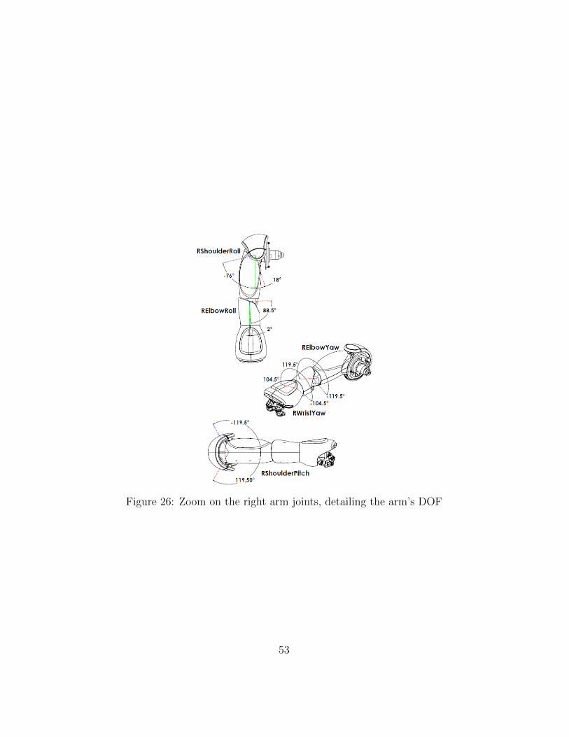
Figure 26: Zoom on the right arm joints, detailing the arm’s DOF
53
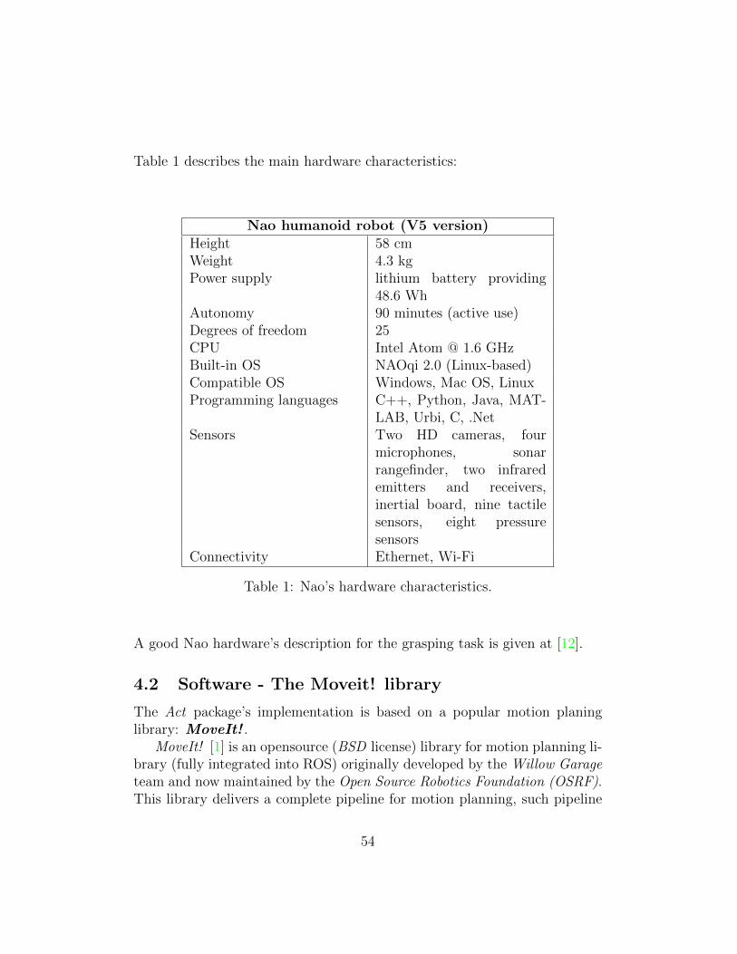
Table 1 describes the main hardware characteristics:
Nao humanoid robot (V5 version)Height 58 cmWeight 4.3 kgPower supply lithium battery providing
48.6 WhAutonomy 90 minutes (active use)Degrees of freedom 25CPU Intel Atom @ 1.6 GHzBuilt-in OS NAOqi 2.0 (Linux-based)Compatible OS Windows, Mac OS, LinuxProgramming languages C++, Python, Java, MAT-
LAB, Urbi, C, .NetSensors Two HD cameras, four
microphones, sonarrangefinder, two infraredemitters and receivers,inertial board, nine tactilesensors, eight pressuresensors
Connectivity Ethernet, Wi-Fi
Table 1: Nao’s hardware characteristics.
A good Nao hardware’s description for the grasping task is given at [12].
4.2 Software - The Moveit! library
The Act package’s implementation is based on a popular motion planinglibrary: MoveIt! .
MoveIt! [1] is an opensource (BSD license) library for motion planning li-brary (fully integrated into ROS) originally developed by the Willow Garageteam and now maintained by the Open Source Robotics Foundation (OSRF).This library delivers a complete pipeline for motion planning, such pipeline
54
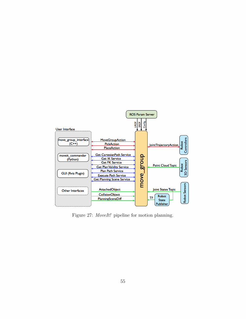
Figure 27: MoveIt! pipeline for motion planning.
55
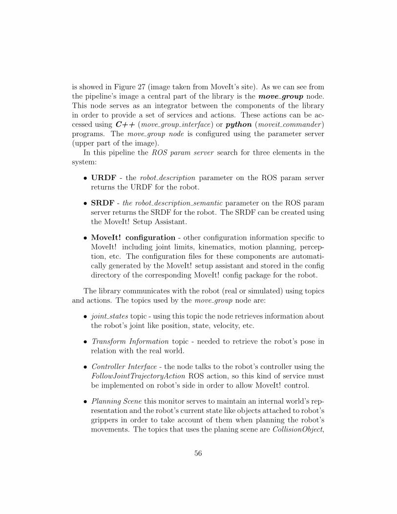
is showed in Figure 27 (image taken from MoveIt’s site). As we can see fromthe pipeline’s image a central part of the library is the move group node.This node serves as an integrator between the components of the libraryin order to provide a set of services and actions. These actions can be ac-cessed using C++ (move group interface) or python (moveit commander)programs. The move group node is configured using the parameter server(upper part of the image).
In this pipeline the ROS param server search for three elements in thesystem:
• URDF - the robot description parameter on the ROS param serverreturns the URDF for the robot.
• SRDF - the robot description semantic parameter on the ROS paramserver returns the SRDF for the robot. The SRDF can be created usingthe MoveIt! Setup Assistant.
• MoveIt! configuration - other configuration information specific toMoveIt! including joint limits, kinematics, motion planning, percep-tion, etc. The configuration files for these components are automati-cally generated by the MoveIt! setup assistant and stored in the configdirectory of the corresponding MoveIt! config package for the robot.
The library communicates with the robot (real or simulated) using topicsand actions. The topics used by the move group node are:
• joint states topic - using this topic the node retrieves information aboutthe robot’s joint like position, state, velocity, etc.
• Transform Information topic - needed to retrieve the robot’s pose inrelation with the real world.
• Controller Interface - the node talks to the robot’s controller using theFollowJointTrajectoryAction ROS action, so this kind of service mustbe implemented on robot’s side in order to allow MoveIt! control.
• Planning Scene this monitor serves to maintain an internal world’s rep-resentation and the robot’s current state like objects attached to robot’sgrippers in order to take account of them when planning the robot’smovements. The topics that uses the planing scene are CollisionObject,
56
PlanningSceneDiff and AllowedCollisionMatrix. Other topics used bythis planning module are the ones produced by RGB-D sensors like thekinect cameras.
Another interesting MoveIt!’s characteristic is that it provides a planningplugin for the Rviz visualization tool which can be used to create planingrequests with the help of a Graphical User Interface.
Using all this information MoveIt! generates a time parametrized trajec-tory consisting of a set of way points. A waypoint is a joint configurationdefined by a tuple (p, v, a, t). The four tuple’s elements (for n joints) are:
1. p - the joint’s positions, p ∈ <n.
2. v - the joint’s velocities, v ∈ <n.
3. a - the joint’s accelerations, a ∈ <n.
4. t - the above vector must be considered at time t, which is a realnumber.
These way points define the trajectory that every joint must follow alongthe time.
In order to solve many trajectory generation’s problems, MoveIt! usessome plugins components. The most important plugins inside the MoveIt!library are:
• The kinematics plugin used to solve the inverse kinematics problem,uses the Kinematics and Dynamics Library (KDL)12.
• The planning plugin uses the Open Motion Planning Library13, thatcontains many implementations of motion planning algorithms.
4.3 The Act ROS package
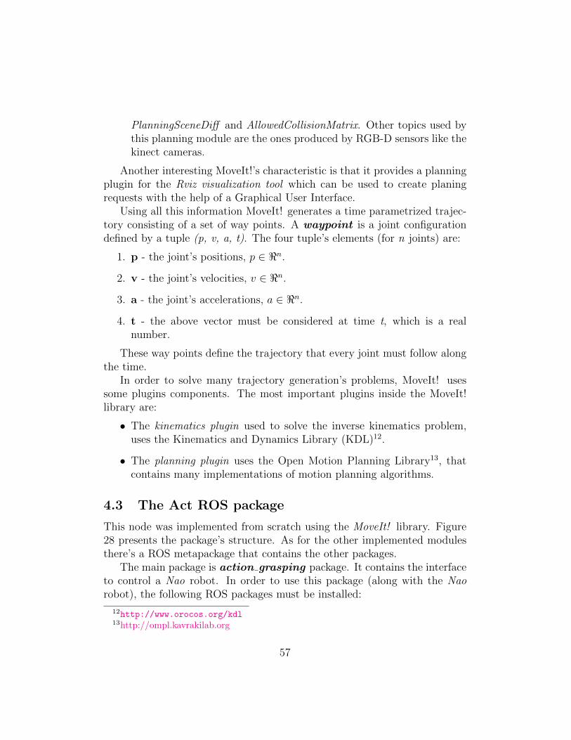
This node was implemented from scratch using the MoveIt! library. Figure28 presents the package’s structure. As for the other implemented modulesthere’s a ROS metapackage that contains the other packages.
The main package is action grasping package. It contains the interfaceto control a Nao robot. In order to use this package (along with the Naorobot), the following ROS packages must be installed:
12http://www.orocos.org/kdl13http://ompl.kavrakilab.org
57
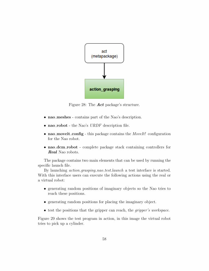
Figure 28: The Act package’s structure.
• nao meshes - contains part of the Nao’s description.
• nao robot - the Nao’s URDF description file.
• nao moveit config - this package contains the MoveIt! configurationfor the Nao robot.
• nao dcm robot - complete package stack containing controllers forReal Nao robots.
The package contains two main elements that can be used by running thespecific launch file.
By launching action grasping nao test.launch a test interface is started.With this interface users can execute the following actions using the real ora virtual robot:
• generating random positions of imaginary objects so the Nao tries toreach these positions.
• generating random positions for placing the imaginary object.
• test the positions that the gripper can reach, the gripper’s workspace.
Figure 29 shows the test program in action, in this image the virtual robottries to pick up a cylinder.
58
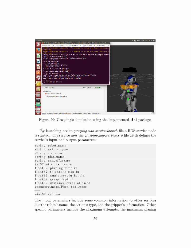
Figure 29: Grasping’s simulation using the implemented Act package.
By launching action grasping nao service.launch file a ROS service nodeis started. The service uses the grasping nao service.srv file witch defines theservice’s input and output parameters:
s t r i n g robot names t r i n g ac t i on types t r i n g arm names t r i n g plan names t r i n g end ef f nameint32 attemps max inf l o a t 3 2 p l a n i n g t i m e i nf l o a t 3 2 t o l e r a n c e m i n i nf l o a t 3 2 a n g l e r e s o l u t i o n i nf l o a t 3 2 g ra sp depth inf l o a t 3 2 d i s t a n c e e r r o r a l l o w e dgeometry msgs /Pose goa l po s e−−−uint32 s u c c e s s
The input parameters include some common information to other serviceslike the robot’s name, the action’s type, and the gripper’s information. Otherspecific parameters include the maximum attempts, the maximum planing
59
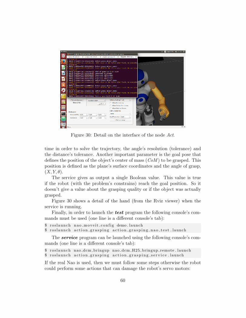
Figure 30: Detail on the interface of the node Act.
time in order to solve the trajectory, the angle’s resolution (tolerance) andthe distance’s tolerance. Another important parameter is the goal pose thatdefines the position of the object’s center of mass (CoM ) to be grasped. Thisposition is defined as the plane’s surface coordinates and the angle of grasp,(X, Y, θ).
The service gives as output a single Boolean value. This value is trueif the robot (with the problem’s constrains) reach the goal position. So itdoesn’t give a value about the grasping quality or if the object was actuallygrasped.
Figure 30 shows a detail of the hand (from the Rviz viewer) when theservice is running.
Finally, in order to launch the test program the following console’s com-mands must be used (one line is a different console’s tab):
$ ros launch nao move i t con f i g demo . launch$ ros launch a c t i o n g r a s p i n g a c t i o n g r a s p i n g n a o t e s t . launch
The service program can be launched using the following console’s com-mands (one line is a different console’s tab):
$ ros launch nao dcm bringup nao dcm H25 bringup remote . launch$ ros launch a c t i o n g r a s p i n g a c t i o n g r a s p i n g s e r v i c e . launch
If the real Nao is used, then we must follow some steps otherwise the robotcould perform some actions that can damage the robot’s servo motors:
60
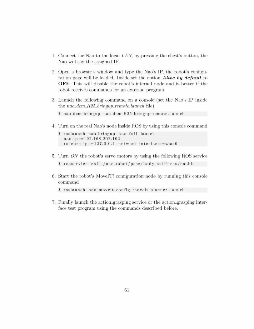
1. Connect the Nao to the local LAN, by pressing the chest’s button, theNao will say the assigned IP.
2. Open a browser’s window and type the Nao’s IP, the robot’s configu-ration page will be loaded. Inside set the option Alive by default toOFF. This will disable the robot’s internal node and is better if therobot receives commands for an external program.
3. Launch the following command on a console (set the Nao’s IP insidethe nao dcm H25 bringup remote.launch file)
$ nao dcm bringup nao dcm H25 bringup remote . launch
4. Turn on the real Nao’s node inside ROS by using this console command
$ ros launch nao bringup n a o f u l l . launchnao ip :=192 .168 .202 .102r o s c o r e i p : = 1 2 7 . 0 . 0 . 1 n e t w o r k i n t e r f a c e :=wlan0
5. Turn ON the robot’s servo motors by using the following ROS service
$ r o s s e r v i c e c a l l / nao robot / pose / b o d y s t i f f n e s s / enable
6. Start the robot’s MoveIT! configuration node by running this consolecommand
$ ros launch nao move i t con f i g move i t p lanner . launch
7. Finally launch the action grasping service or the action grasping inter-face test program using the commands described before.
61
5 Experiments
Experiments aim to provide timing results on Cloud access and ontologicaldata retrieval and on grasping execution. The Cloud Engine have been inte-grated inside the Cloud environment of the CORE project [27], which is avail-able on the CloudLab platform 14 cluster under the project core-robotics.It consists of one x86 node running Ubuntu 14.04 with ROS Indigo installed.To test the recognition pipeline a dataset was used to populate the ontologyand the related folders, the Object Segmentation Database (OSD) [4]: a dataset of 726 MB currently containing 111 different objects, all characterized bya 2D color image and a point cloud. This chapter differentiates the followingexperiment’s types:
• Recognition engine timing retrieval - here we are measuring the timethat the object takes to arrive to the server and different times of therecognition pipeline as described in Figure 17.
• Grasping generation timing - in this experiments the grasp generationtime is measured when using the proposed act module.
The client-side ROS nodes run on a lowend Thinkpad laptop with anIntel’s Core2Duo and 4GB of RAM.
5.1 Recognition engine
As explained in the Cloud Engine section the recognition pipeline includesdifferent phases to retrieve similar objects in the RTASK Ontology. A impor-tant step inside the pipeline is the time that the Engine employs to extractthe features of the object. The features extracted are the SIFT features andthe OpenCV’s implementation of the SIFT algorithm is used.
Table 2 shows the time that the Cloud engine employs to extract thefeature’s objects. Using the entire dataset ([4]) the server employs only 45seconds to extract and write on a binary file the features of 111 objects. Butin this case the most interesting time is the second, for one object it employsonly .037 seconds. This is the case we have when a new retrieve query arrivesfrom a robot.
Table 3 shows the time that the Cloud engine employs to match theentire dataset image’s pairs setting the number of inliers. Using 300 inliers
14http://cloudlab.us
62
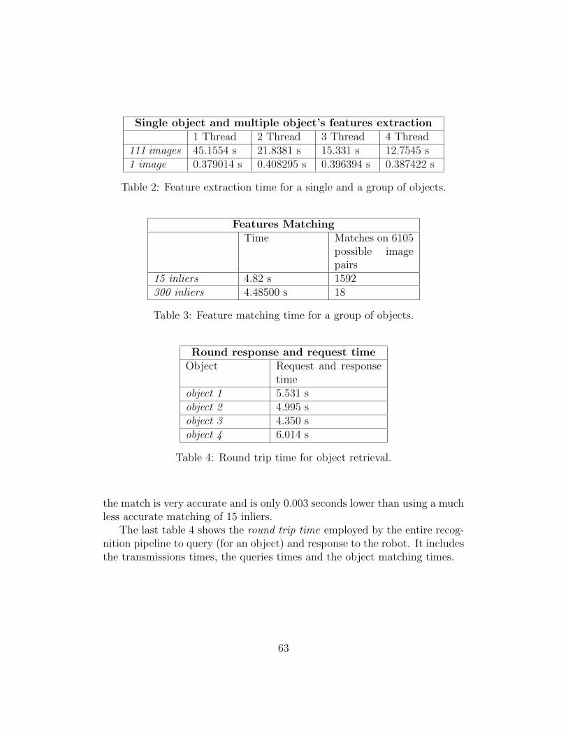
Single object and multiple object’s features extraction1 Thread 2 Thread 3 Thread 4 Thread
111 images 45.1554 s 21.8381 s 15.331 s 12.7545 s1 image 0.379014 s 0.408295 s 0.396394 s 0.387422 s
Table 2: Feature extraction time for a single and a group of objects.
Features MatchingTime Matches on 6105
possible imagepairs
15 inliers 4.82 s 1592300 inliers 4.48500 s 18
Table 3: Feature matching time for a group of objects.
Round response and request timeObject Request and response
timeobject 1 5.531 sobject 2 4.995 sobject 3 4.350 sobject 4 6.014 s
Table 4: Round trip time for object retrieval.
the match is very accurate and is only 0.003 seconds lower than using a muchless accurate matching of 15 inliers.
The last table 4 shows the round trip time employed by the entire recog-nition pipeline to query (for an object) and response to the robot. It includesthe transmissions times, the queries times and the object matching times.
63
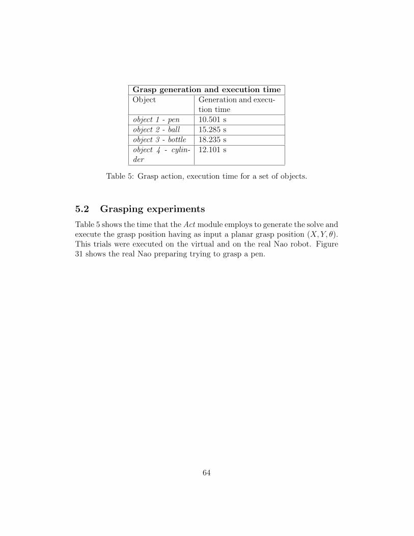
Grasp generation and execution timeObject Generation and execu-
tion timeobject 1 - pen 10.501 sobject 2 - ball 15.285 sobject 3 - bottle 18.235 sobject 4 - cylin-der
12.101 s
Table 5: Grasp action, execution time for a set of objects.
5.2 Grasping experiments
Table 5 shows the time that the Act module employs to generate the solve andexecute the grasp position having as input a planar grasp position (X, Y, θ).This trials were executed on the virtual and on the real Nao robot. Figure31 shows the real Nao preparing trying to grasp a pen.
64
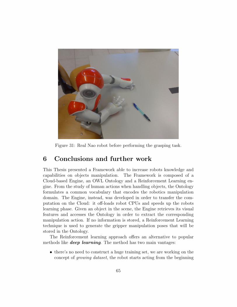
Figure 31: Real Nao robot before performing the grasping task.
6 Conclusions and further work
This Thesis presented a Framework able to increase robots knowledge andcapabilities on objects manipulation. The Framework is composed of aCloud-based Engine, an OWL Ontology and a Reinforcement Learning en-gine. From the study of human actions when handling objects, the Ontologyformulates a common vocabulary that encodes the robotics manipulationdomain. The Engine, instead, was developed in order to transfer the com-putation on the Cloud: it off-loads robot CPUs and speeds up the robotslearning phase. Given an object in the scene, the Engine retrieves its visualfeatures and accesses the Ontology in order to extract the correspondingmanipulation action. If no information is stored, a Reinforcement Learningtechnique is used to generate the gripper manipulation poses that will bestored in the Ontology.
The Reinforcement learning approach offers an alternative to popularmethods like deep learning. The method has two main vantages:
• there’s no need to construct a huge training set, we are working on theconcept of growing dataset, the robot starts acting from the beginning
65
without the need of a training phase.
• learning is always present, every input changes the robot’s internalworld representation. The long-term model of the world is stored onthe ontology database and shared with others robots.
An extension of the Thesis’s work could involve:
• Using a bigger robot for the grasping task like the Universal Robotics’sUR-10 .
• Using a different segmentation method, capable of working with smallerpoint clouds. So the manipulation task can be tested on small objects.
• Using the entire pipeline on a group of robots in order to demonstratethe scalability of the Cloud-based engine.
• Performing large-scale experiments using the implemented Reinforce-ment learning algorithm, to understand how fast the robot learns tograsp unknown objects.
Finally the complete pipeline source’s code will be released inside theIAS-LAB repository15 under the project’s name cloud based rl .
15https://github.com/iaslab-unipd
66
7 Ringraziamenti
Ringrazio di cuore alla mia famiglia per l’appoggio che mi ha dato in tuttiquesti anni, Maximiliano, Alberto e Isabel. Un rigraziamento speciale aHortensia e Sita.
Ringrazio al Professore Enrico Pagello e alla Dott.ssa Elisa Tosello perl’opportunita, che mi hanno dato, di sviluppare un lavoro di ricerca interes-sante e innovativo, e per tutti i consigli che mi hanno dato nel corso dellosviluppo della Tesi.
Ringrazio infine tutti gli amici per tutto quello che abbiamo condivisonegli anni, Marco, Giuliano, Marco, Giuseppe, Duilio, Massimo.
Ringrazio a Sabrina e Fabiana, per tutto quello che abbiamo condivisonegli anni e per la mano con le correzioni della Tesi stessa.
Infine ringrazio tutti i colleghi di lavoro per l’aiuto e la pazienza che hannoportato in questo periodo di studio.
67
References
[1] I. sucan and s. chitta, moveit! [Online] Available: http://moveit.ros.org.
[2] Official wiki of ros middleware. http://wiki.ros.org/.
[3] J. Bagnell A. Boularias and A. Stent. Learning to manipulate unknownobjects in clutter by reinforcement. AAAI, 2015.
[4] J. Prankl M. Zillich A. Richtsfeld, T. Morwald and M. Vincze. Seg-mentation of unknown objects in indoor environments. IROS, pages4791–4796, 2012.
[5] J. Prankl M. Zillich A. Richtsfeld, T. Morwald and M. Vincze. Pointcloud culling for robot vision tasks under communication constraints.Proceedings of the 2014 IEEE/RSJ International Conference on Intelli-gent Robots and Systems (IROS), pages 4791–4796, 2014.
[6] R. Platt. A. ten Pas. Using geometry to detect grasp poses in 3d pointclouds. International Symposium on Robotics Research (ISRR), Italy,2015.
[7] J. Papon C. Stein, M. Schoeler and F. Woergoetter. Object partition-ing using local convexity. Computer Vision and Pattern Recognition(CVPR), 2014 IEEE Conference on, 2014.
[8] N. Dalal and B. Triggs. Histograms of oriented gradients for humandetection. IIEEE Computer Society Conference on Computer Visionand Pattern Recognition, Vol. 1, pp. 886–893, 2005.
[9] N. Dalal and B. Triggs. Histograms of oriented gradients for humandetection. IIEEE Computer Society Conference on Computer Visionand Pattern Recognition, Vol. 1, pp. 886–893, 2005.
[10] A. Gatto Castro E. Tosello, Z. Fan and E. Pagello. Cloud-based taskplanning for smart robots. 14th IAS — International Conference onIntelligent Autonomous Systems, 2016.
[11] M. Fischler and R. Bolle. Random sample consensus. a paradimg formodel fitting with applications to image analysis and automated cartog-raphy. Communications of the ACM Volume 24, Number 6, 1981.
68
[12] G. Cotugno H. Mellmann. Dynamic motion control: Adaptive bimanualgrasping for a humanoid robot. Fundamenta Informaticae 112, 89-101,2011.
[13] J. Wu H. Cui J. Cheng, C. Leng and H. Lu. Fast and accurate imagematching with cascade hashing for 3d reconstruction. The IEEE Con-ference on Computer Vision and Pattern Recognition (CVPR), 2014.
[14] R. B. Rusu M. Gedikli S. Beetz J. Kammerl, N. Blodow and E. Stein-bach. Real-time compression of point cloud streams. Proceedings ofthe 2012 IEEE International Conference on Robotics and Automation(ICRA), pp. 778–785., 2012.
[15] M. Schoeler J. Papon, A. Abramov and F. Woergoetter. Voxel cloud con-nectivity segmentation - supervoxels for point clouds. Computer Visionand Pattern Recognition (CVPR), 2013 IEEE Conference on, 2013.
[16] B. Karan. Calibration of kinect-type rgb-d sensors for robotic applica-tions. FME Transactions, 2015.
[17] D. Lowe. Distinctive image features from scale-invariant keypoints. In-ternational Journal of Computer Vision, 60, 2, pp. 91-110, 2004.
[18] Paul Malmsten. Object discovery with a Microsoft Kinect, 2012.
[19] G. Alenya N. Covallero. Grasping novel objects. Technical Report IRI-TR-16-01, Universitat Politecnica de Catalunya -Institut de Robotica iInformatica Industrial (IRI), May 2016.
[20] R. d’Andrea O. Zweigle, R. van de Molengraft and K. Haussermann.Roboearth: connecting robots worldwide. Proceedings of the 2nd Inter-national Conference on Interaction Sciences: Information Technology,Culture and Human. ACM, pp. 184–191, 2009.
[21] L. Pinto and A. Gupta. Supersizing self-supervision: Learning to graspfrom 50k tries and 700 robot hours. CoRR, abs/1509.06825, 2015.
[22] N. Blodow R. B. Rusu and M. Beetz. Fast point feature histograms(fpfh) for 3d registration. Robotics and Automation, (ICRA). IEEEInternational Conference on,pages 3212 –3217, 2009.
69
[23] A. Barto R. Sutton. Reinforcement learning: An introduction. Freeonline version from https://webdocs.cs.ualberta.ca/ sutton/book/the-book.html, 2015.
[24] Craig I. Schlenoff. An Overview of the IEEE Ontology for Robotics andAutomation (ORA) Standardization Effort. In Standardized KnowledgeRepresentation and Ontologies for Robotics and Automation, Workshopon the 18th, pages 1–2, Chicago, Illinois, USA, 2014.
[25] Chris Sweeney. Theia multiview geometry library: Tutorial & reference.http://theia-sfm.org.
[26] P. Stone T. Hester. The open-source texplore code release for reinforce-ment learning on robots. RoboCup-2013 Robot Soccer World Cup XVISpringer Verlag, 2013.
[27] J. Spruth W.J. Beksi and N. Papanikolopoulos. Core: A cloud-basedobject recognition engine for robotics. IEEE/RSJ International Confer-ence on Intelligent Robots and Systems (IROS), 2015.
70