Embed Size (px)
Citation preview
1
Chapter 4
Layer 2 to Layer 3 Boundary Design
Objectives
Designs to support the Layer 2 to Layer 3 boundary in enterprise campus networks.
Includes being able to meet these objectives: Describe and select the appropriate Layer 2
to Layer 3 boundary design models Describe and avoid potential design issues
with the design models
2
Layer 2 Distribution Switch Interconnection
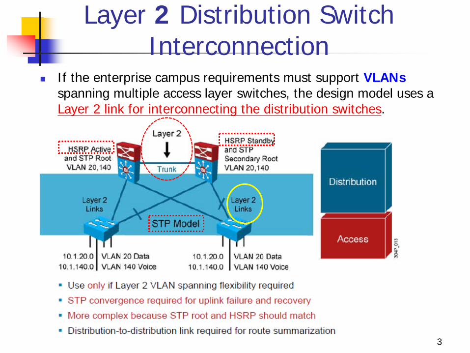
If the enterprise campus requirements must support VLANs spanning multiple access layer switches, the design model uses a Layer 2 link for interconnecting the distribution switches.
3
Layer 2 Distribution Switch Interconnection
This design is more complex than the Layer 3 interconnection of the distribution switches.
The STP convergence process will be initiated for uplink failures and recoveries.
Following steps to improve this suboptimal design: 1. Must to use Rapid STP (RSTP).
RPVST+ is a Cisco enhancement of RSTP that uses PVST+. It provides a separate instance of 802.1W per VLAN.
supports PortFast, UplinkFast, BackboneFast, BPDU guard, BPDU filter, root guard, and loop guard.
2. Provide a Layer 2 trunk between the two distribution switches to avoid unexpected traffic paths and multiple convergence events.
4
Layer 2 Distribution Switch Interconnection
3. If you choose to load-balance VLANs across uplinks, be sure to place the Hot Standby Router Protocol (HSRP) primary and the STP primary on the same distribution layer switch.
4. The HSRP and RSTP root should be collocated on the same distribution switches to avoid using the interdistribution link for transit.
5
Layer 3 Distribution Switch Interconnection
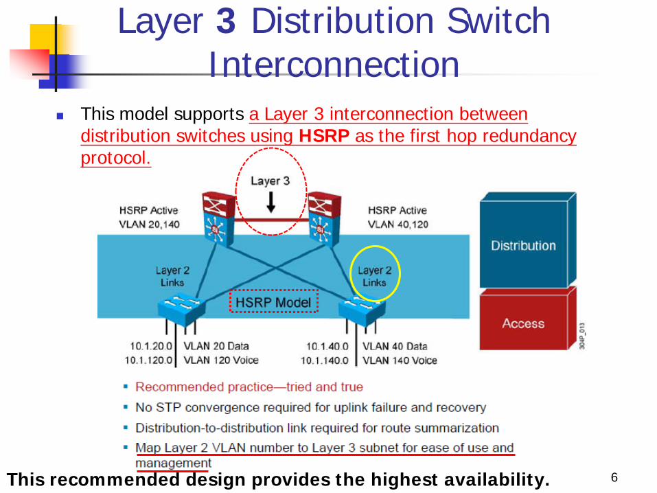
This model supports a Layer 3 interconnection between distribution switches using HSRP as the first hop redundancy protocol.
6 This recommended design provides the highest availability.
HSRP
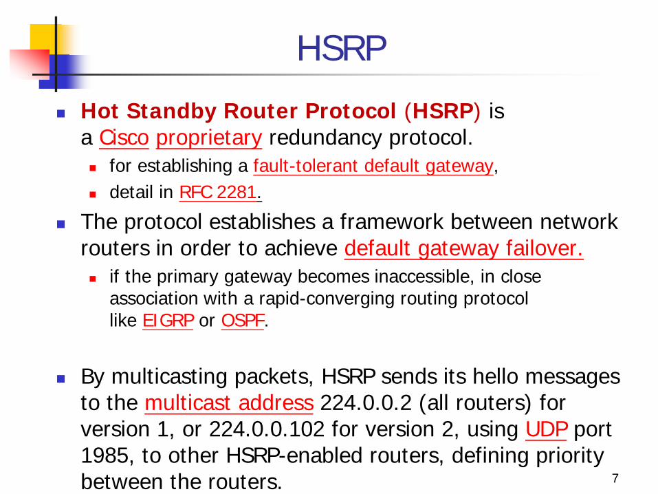
Hot Standby Router Protocol (HSRP) is a Cisco proprietary redundancy protocol. for establishing a fault-tolerant default gateway, detail in RFC 2281.
The protocol establishes a framework between network routers in order to achieve default gateway failover. if the primary gateway becomes inaccessible, in close
association with a rapid-converging routing protocol like EIGRP or OSPF.
By multicasting packets, HSRP sends its hello messages to the multicast address 224.0.0.2 (all routers) for version 1, or 224.0.0.102 for version 2, using UDP port 1985, to other HSRP-enabled routers, defining priority between the routers. 7
HSRP
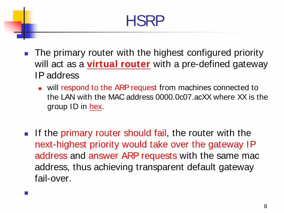
The primary router with the highest configured priority will act as a virtual router with a pre-defined gateway IP address will respond to the ARP request from machines connected to
the LAN with the MAC address 0000.0c07.acXX where XX is the group ID in hex.
If the primary router should fail, the router with the
next-highest priority would take over the gateway IP address and answer ARP requests with the same mac address, thus achieving transparent default gateway fail-over.
8
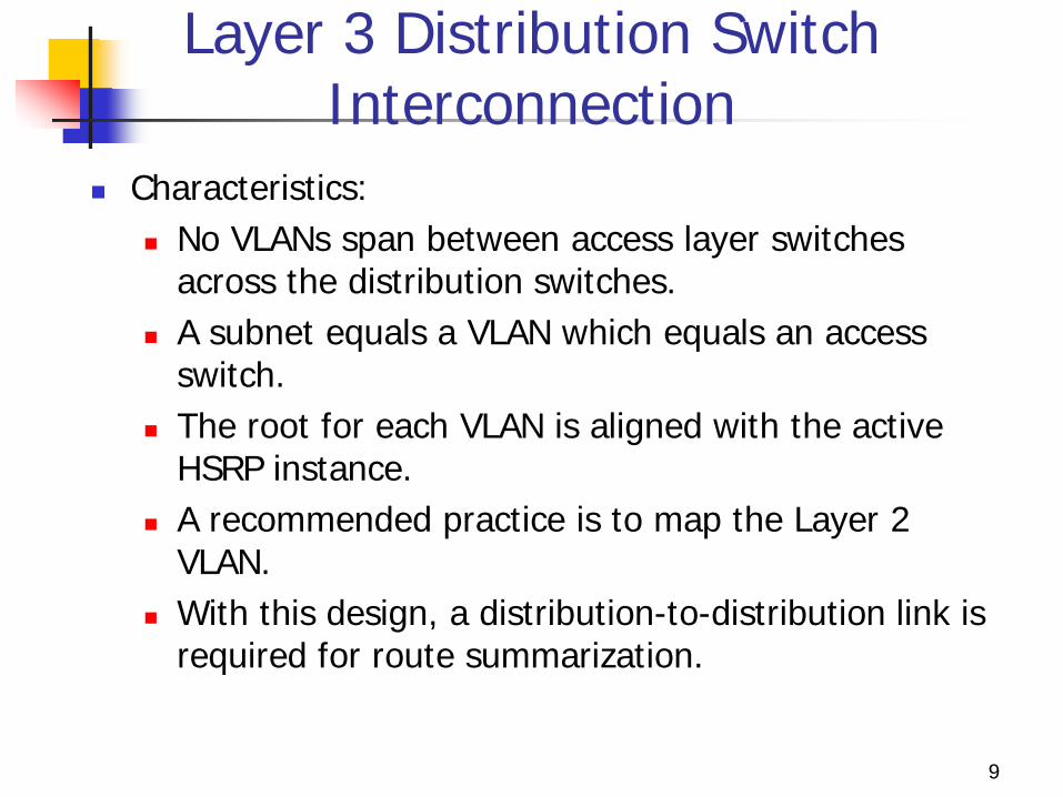
Layer 3 Distribution Switch Interconnection
Characteristics: No VLANs span between access layer switches
across the distribution switches. A subnet equals a VLAN which equals an access
switch. The root for each VLAN is aligned with the active
HSRP instance. A recommended practice is to map the Layer 2
VLAN. With this design, a distribution-to-distribution link is
required for route summarization.
9
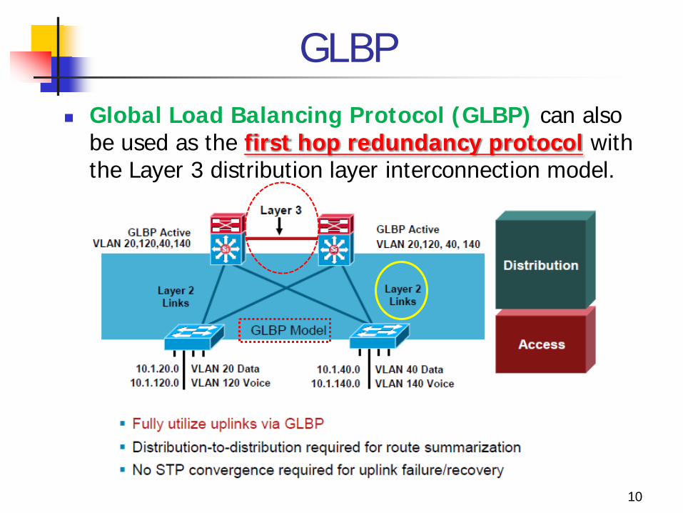
GLBP Global Load Balancing Protocol (GLBP) can also
be used as the first hop redundancy protocol with the Layer 3 distribution layer interconnection model.
10
GLBP
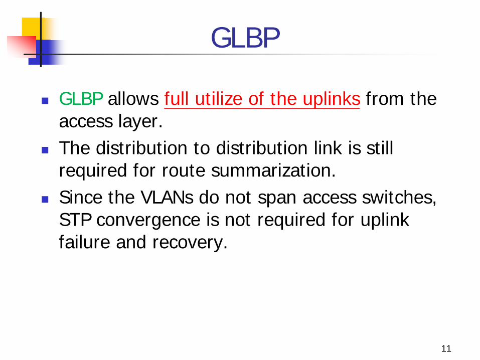
GLBP allows full utilize of the uplinks from the access layer.
The distribution to distribution link is still required for route summarization.
Since the VLANs do not span access switches, STP convergence is not required for uplink failure and recovery.
11
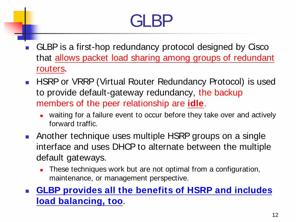
GLBP GLBP is a first-hop redundancy protocol designed by Cisco
that allows packet load sharing among groups of redundant routers.
HSRP or VRRP (Virtual Router Redundancy Protocol) is used to provide default-gateway redundancy, the backup members of the peer relationship are idle. waiting for a failure event to occur before they take over and actively
forward traffic.
Another technique uses multiple HSRP groups on a single interface and uses DHCP to alternate between the multiple default gateways. These techniques work but are not optimal from a configuration,
maintenance, or management perspective.
GLBP provides all the benefits of HSRP and includes load balancing, too.
12
Example
13
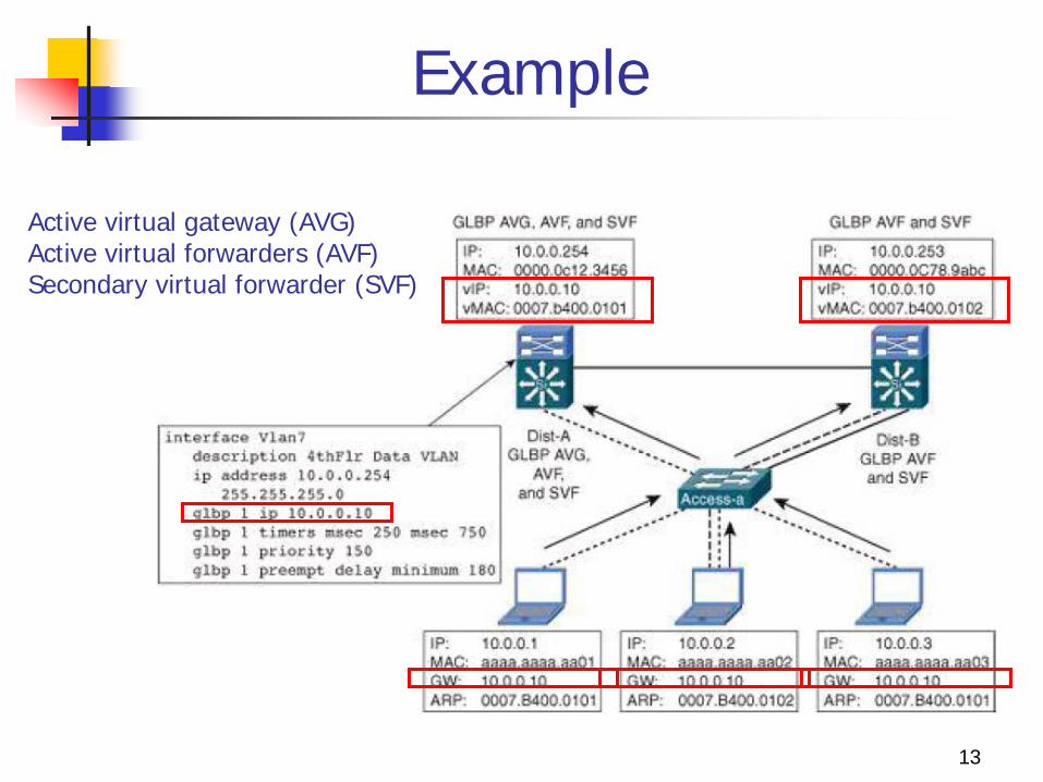
Active virtual gateway (AVG) Active virtual forwarders (AVF) Secondary virtual forwarder (SVF)
GLBP Advantage:
1. allows for the automatic selection and simultaneous use of multiple available gateways as well as automatic failover between those gateways
2. none of the clients has to be pointed toward a specific gateway address; they can all have the same default gateway set to the virtual router IP address.
Principle : Single virtual IP address and multiple virtual MAC addresses 1. As a client sends an ARP request looking for the virtual router
IP address, 2. GLBP sends back an ARP reply with the virtual MAC address of
a selected router in the group. 3. The result is that all clients use the same gateway IP address
but have differing MAC addresses for it.
14
Layer 3 Access to Distribution Interconnection
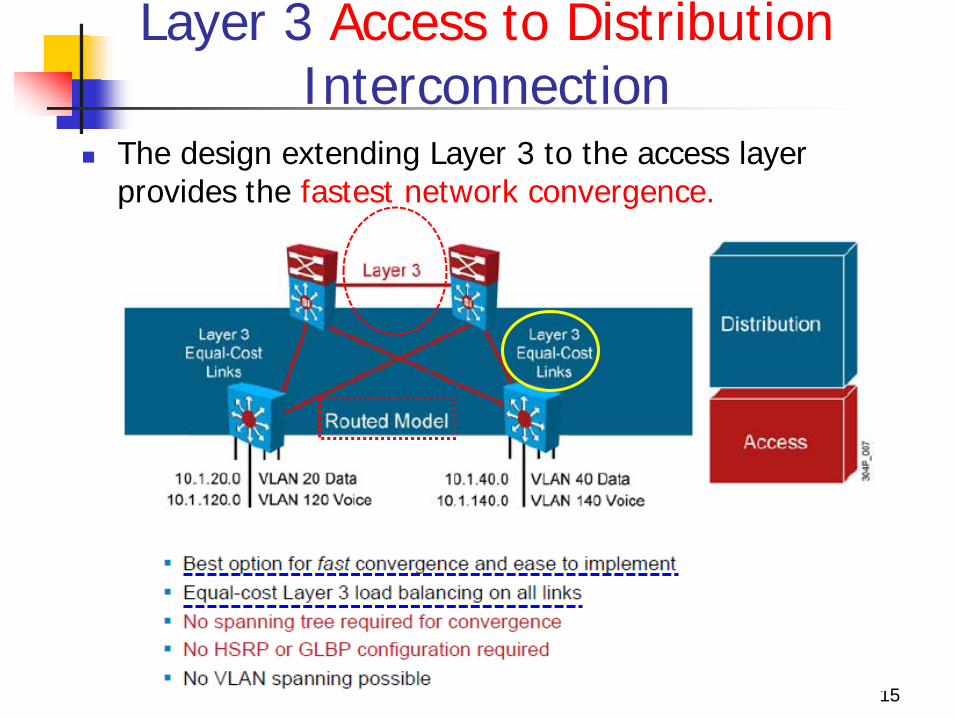
The design extending Layer 3 to the access layer provides the fastest network convergence.
15
Layer 3 Access to Distribution Interconnection
A routing protocol (i.e., EIGRP) can achieve better convergence results than designs that rely on STP to resolve convergence events.
A routing protocol can even achieve better convergence results than the time-tested design placing the Layer 2 to Layer 3 boundary at the distribution layer.
The design is easier to implement than configuring Layer 2 in the distribution layer because you do not need to align STP with HSRP or GLBP. No HSRP or GLBP configuration.
VLANs can not span access switches in this design.
16
Layer 3 Access to Distribution Interconnection
This design supports equal-cost Layer 3 load balancing on all links between the network switches.
Because this switch is a multilayer switch, it serves as the default gateway for the end users. VLANs cannot span access switches in this design.
Drawback: However, some additional complexity associated with
uplink IP addressing and subnetting as well as the loss of flexibility are associated with this design alternative.
Deploying a Layer 3 access layer may be prohibited because of conformance with the existing architecture, price of multilayer switches, and application or service requirements. 17
Experience The convergence time required to reroute around a failed access-
to-distribution layer uplink is reliably under 200 ms as compared to 900 ms for the design placing the Layer 2 and Layer 3 boundary at the distribution layer.
Return-path traffic is also in the sub-200 ms of convergence time for an EIGRP reroute, again compared to 900 ms for the traditional Layer 2 to Layer 3 distribution layer model.
Because both EIGRP and OSPF loads share over equal-cost paths, this design provides a convergence benefit similar to GLBP. Approximately 50 percent of the hosts are not affected by a
convergence event because their traffic is not flowing over the link or through the failed node.
Routing in the access layer is not as widely deployed in the enterprise environment as the Layer 2 and Layer 3 distribution layer boundary model.
18
19
Enhanced Interior Gateway Protocol (EIGRP)
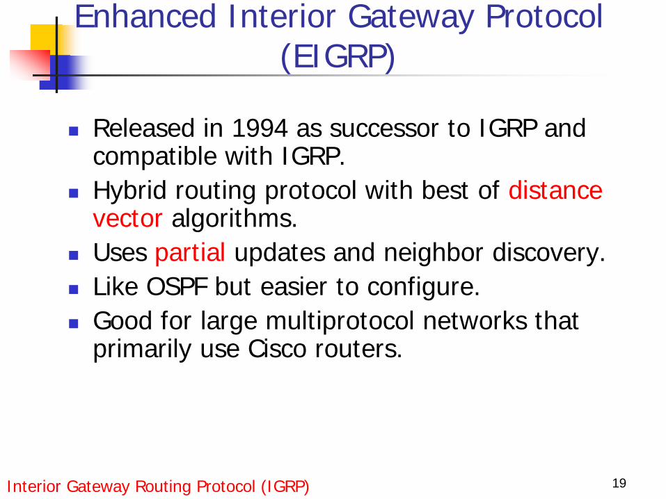
Released in 1994 as successor to IGRP and compatible with IGRP.
Hybrid routing protocol with best of distance vector algorithms.
Uses partial updates and neighbor discovery. Like OSPF but easier to configure. Good for large multiprotocol networks that
primarily use Cisco routers.
Interior Gateway Routing Protocol (IGRP)
20
EIGRP key features
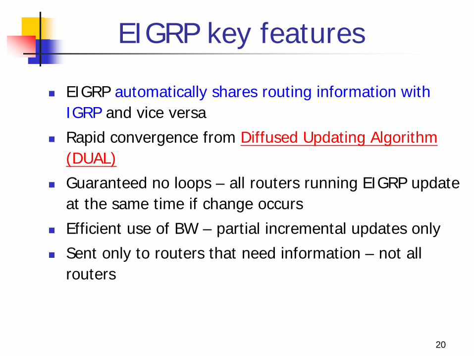
EIGRP automatically shares routing information with IGRP and vice versa
Rapid convergence from Diffused Updating Algorithm (DUAL)
Guaranteed no loops – all routers running EIGRP update at the same time if change occurs
Efficient use of BW – partial incremental updates only Sent only to routers that need information – not all
routers
21
EIGRP key features
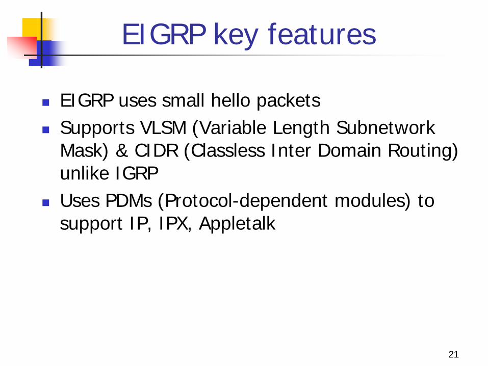
EIGRP uses small hello packets Supports VLSM (Variable Length Subnetwork
Mask) & CIDR (Classless Inter Domain Routing) unlike IGRP
Uses PDMs (Protocol-dependent modules) to support IP, IPX, Appletalk
22
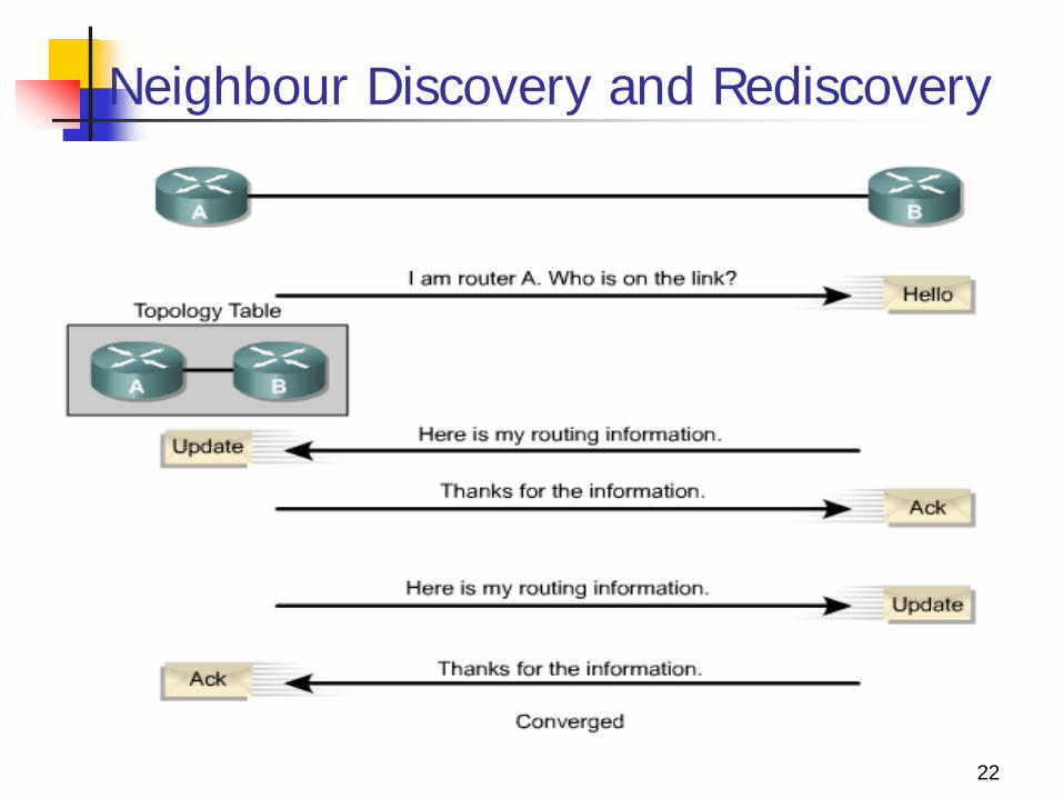
Neighbour Discovery and Rediscovery
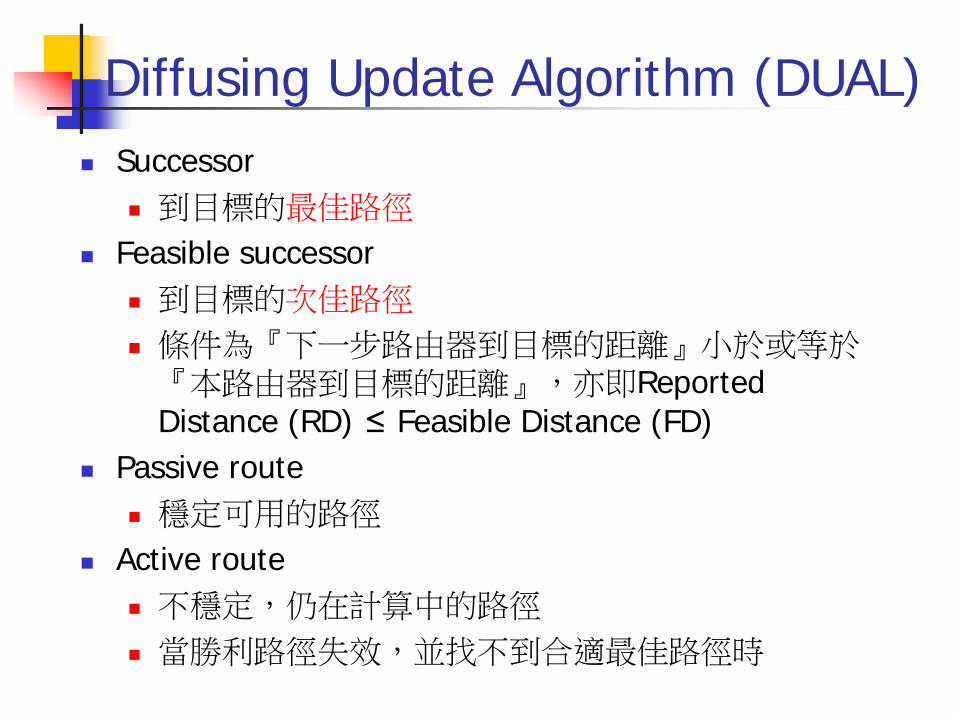
Diffusing Update Algorithm (DUAL) Successor
到目標的最佳路徑 Feasible successor
到目標的次佳路徑 條件為『下一步路由器到目標的距離』小於或等於『本路由器到目標的距離』,亦即Reported Distance (RD) ≤ Feasible Distance (FD)
Passive route 穩定可用的路徑
Active route 不穩定,仍在計算中的路徑 當勝利路徑失效,並找不到合適最佳路徑時
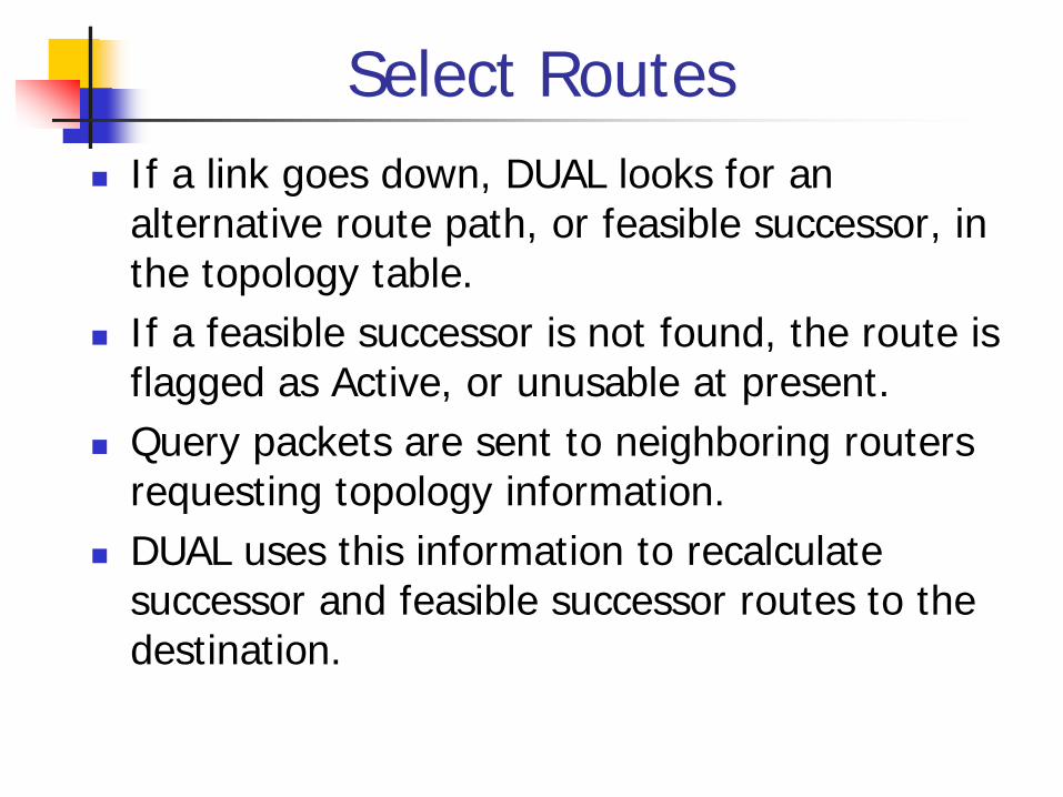
Select Routes If a link goes down, DUAL looks for an
alternative route path, or feasible successor, in the topology table.
If a feasible successor is not found, the route is flagged as Active, or unusable at present.
Query packets are sent to neighboring routers requesting topology information.
DUAL uses this information to recalculate successor and feasible successor routes to the destination.
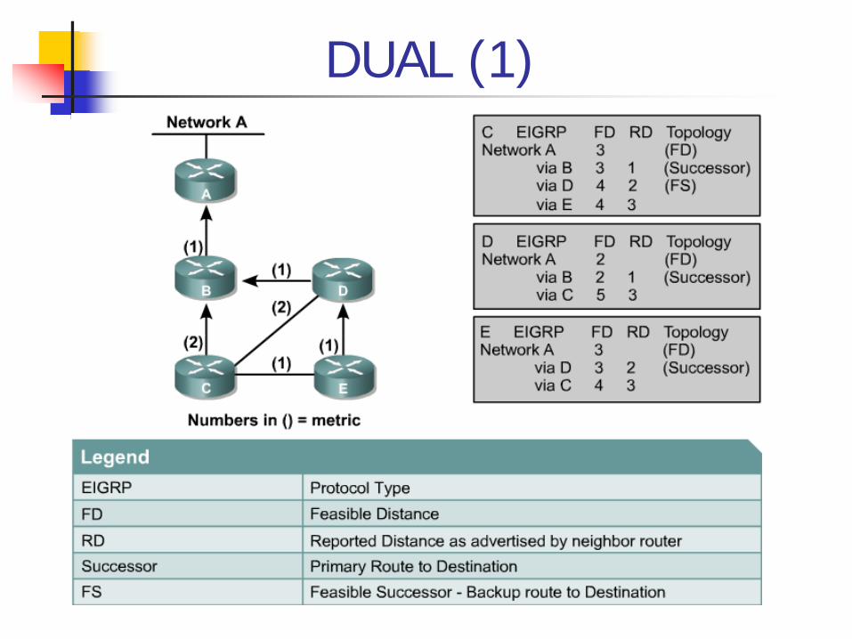
DUAL (1)
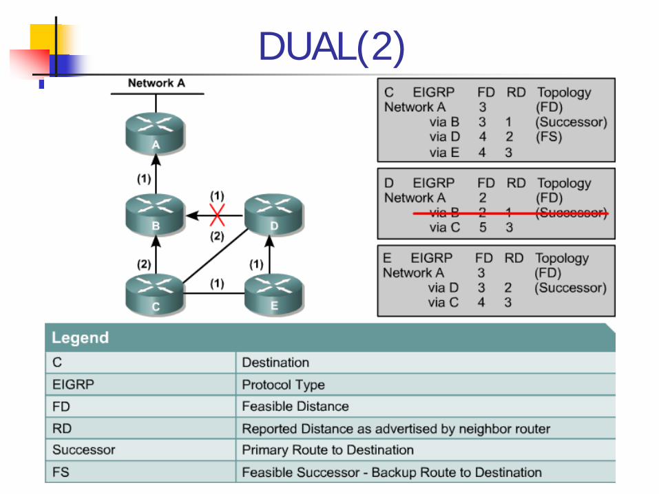
DUAL(2)
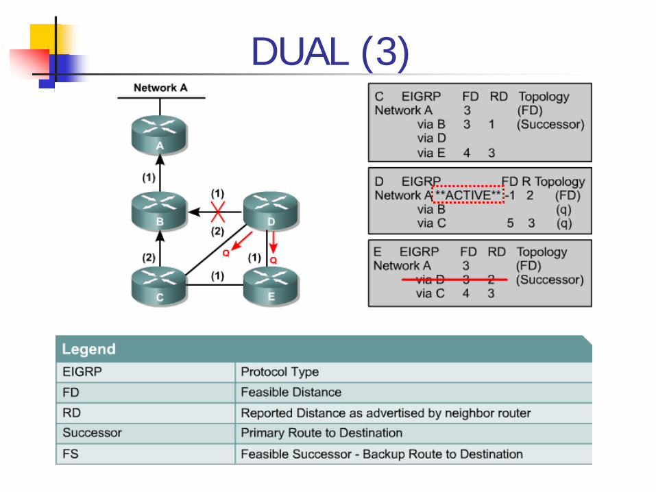
DUAL (3)
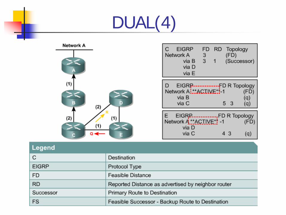
DUAL(4)
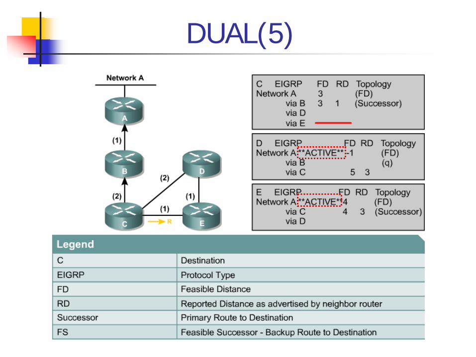
DUAL(5)
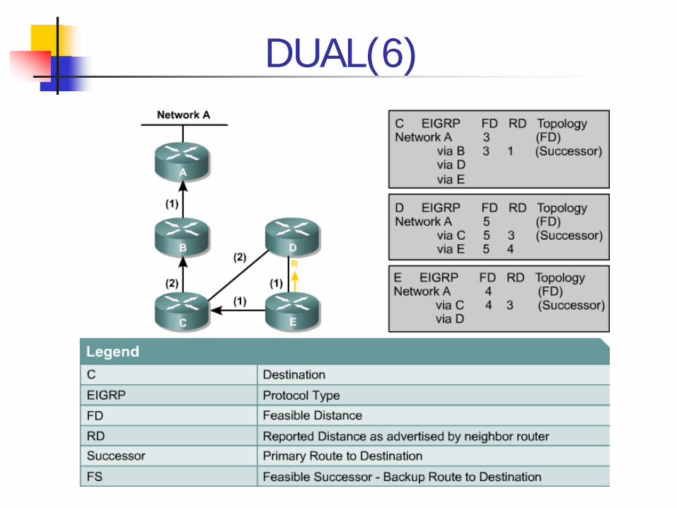
DUAL(6)
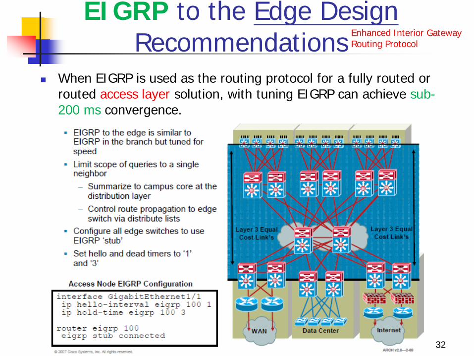
EIGRP to the Edge Design Recommendations
When EIGRP is used as the routing protocol for a fully routed or routed access layer solution, with tuning EIGRP can achieve sub-200 ms convergence.
32
Enhanced Interior Gateway Routing Protocol
EIGRP to the Edge Design Recommendations
This confines impact of an individual access link failure to the distribution pair by stopping EIGRP queries from propagating beyond the core of the network. Configure all edge switches to use EIGRP stub, so
the edge devices are not queried by the distribution switches for routes.
EIGRP stub nodes are not able to act as transit nodes and do not participate in EIGRP query processing.
When the distribution node learns through the EIGRP hello packets that it is talking to a stub node, it does not flood queries to that node.
33
EIGRP to the Edge Design Recommendations
Control route propagation to edge switches using distribute lists. The access switches only need a default route to the
distribution switches.
An outbound distribute list applied to all interfaces facing the access layer from the distribution switch will conserve memory and optimize performance at the access layer.
35
EIGRP stub
stub receive-only (optional) Sets the router as a receive-only neighbor.
stub static (optional) Advertises static routes.
stub connected (optional) Advertises connected routes.
stub summary (optional) Advertises summary routes.
36
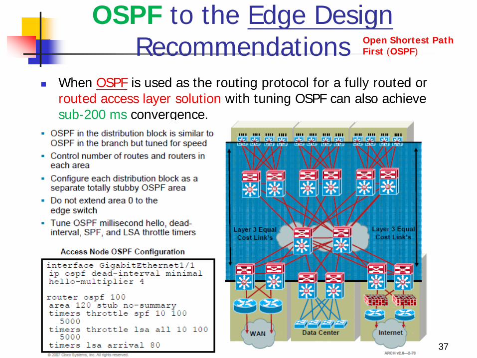
OSPF to the Edge Design Recommendations
When OSPF is used as the routing protocol for a fully routed or routed access layer solution with tuning OSPF can also achieve sub-200 ms convergence.
37
Open Shortest Path First (OSPF)
38
Open Shortest Path First (OSPF) routing protocol.
Dynamic Routing Protocol
39
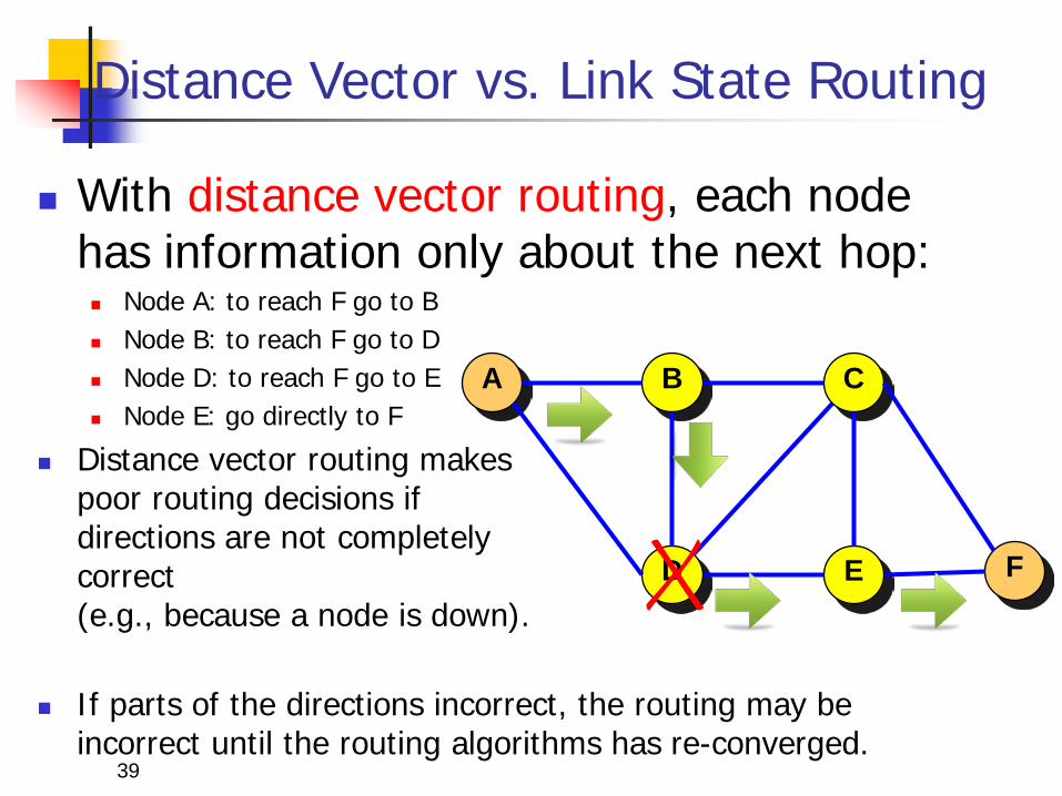
Distance Vector vs. Link State Routing
With distance vector routing, each node has information only about the next hop: Node A: to reach F go to B Node B: to reach F go to D Node D: to reach F go to E Node E: go directly to F
Distance vector routing makes poor routing decisions if directions are not completely correct (e.g., because a node is down).
If parts of the directions incorrect, the routing may be
incorrect until the routing algorithms has re-converged.
A B C
D E F
40
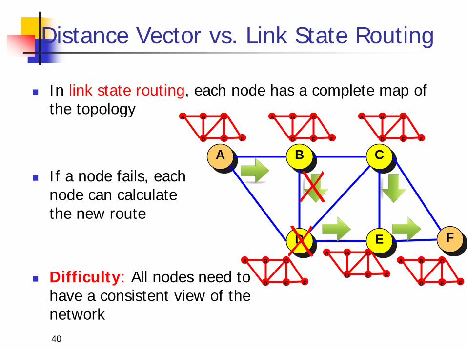
Distance Vector vs. Link State Routing
In link state routing, each node has a complete map of the topology
If a node fails, each node can calculate the new route
Difficulty: All nodes need to have a consistent view of the network
A B C
D E F
A B C
D E F
A B C
D E F
A B C
D E F
A B C
D E F
A B C
D E F
A B C
D E F
41
Link State Routing: Properties
Each node requires complete topology information
Link state information must be flooded to all nodes
Guaranteed to converge
42
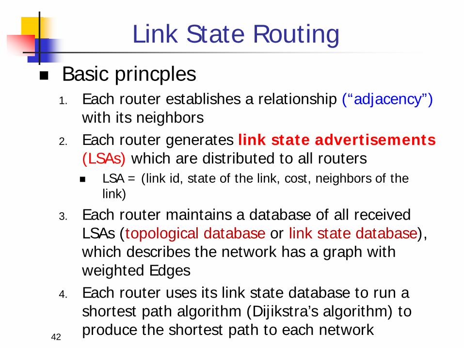
Link State Routing Basic princples
1. Each router establishes a relationship (“adjacency”) with its neighbors
2. Each router generates link state advertisements (LSAs) which are distributed to all routers LSA = (link id, state of the link, cost, neighbors of the
link)
3. Each router maintains a database of all received LSAs (topological database or link state database), which describes the network has a graph with weighted Edges
4. Each router uses its link state database to run a shortest path algorithm (Dijikstra’s algorithm) to produce the shortest path to each network
43
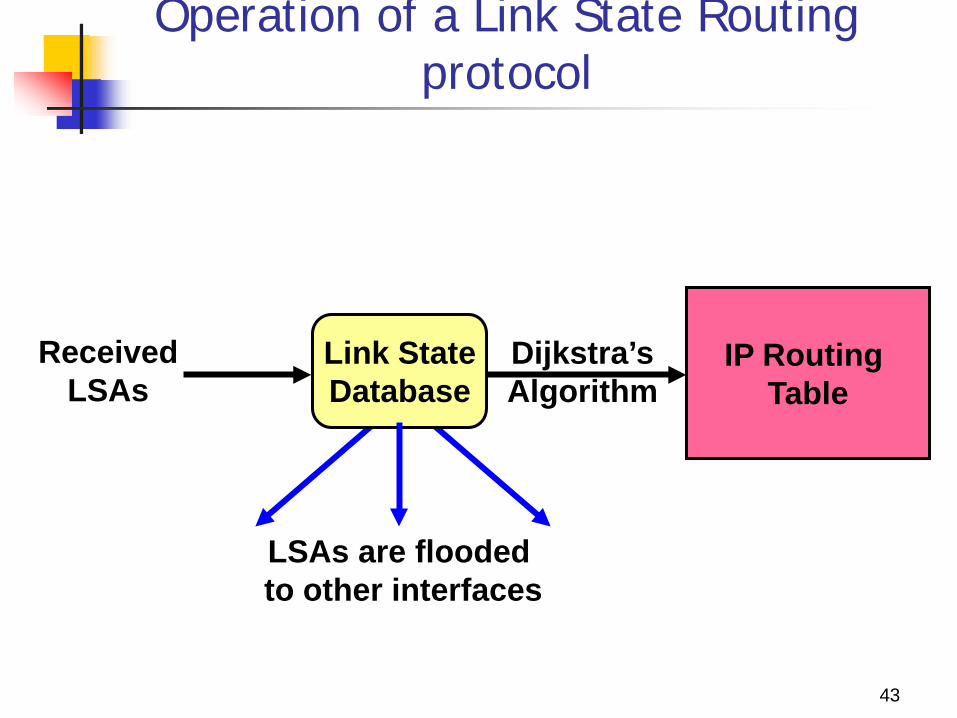
Operation of a Link State Routing protocol
Received LSAs
IP Routing Table
Dijkstra’s Algorithm
Link State Database
LSAs are flooded to other interfaces
44
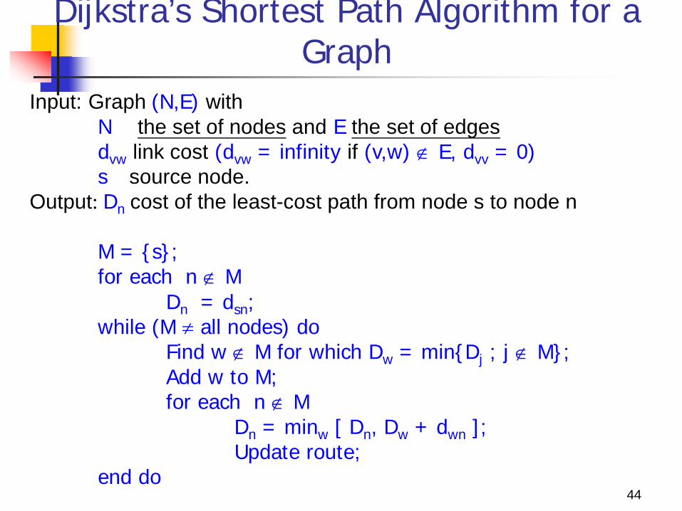
Dijkstra’s Shortest Path Algorithm for a Graph
Input: Graph (N,E) with N the set of nodes and E the set of edges dvw link cost (dvw = infinity if (v,w) ∉ E, dvv = 0) s source node. Output: Dn cost of the least-cost path from node s to node n M = {s}; for each n ∉ M Dn = dsn; while (M ≠ all nodes) do Find w ∉ M for which Dw = min{Dj ; j ∉ M}; Add w to M; for each n ∉ M Dn = minw [ Dn, Dw + dwn ]; Update route; end do
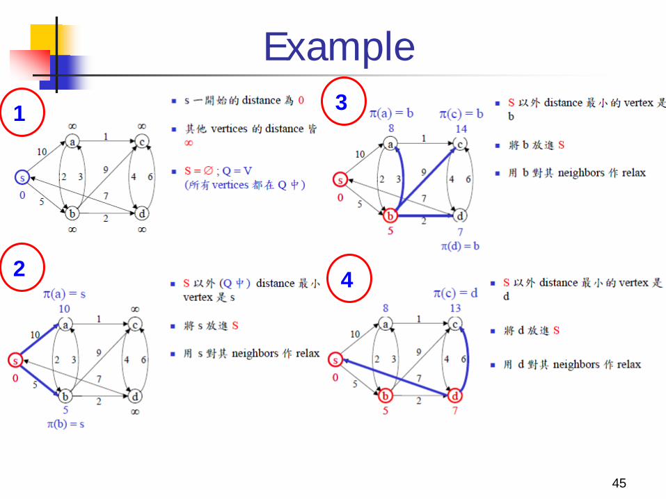
Example
45
1
2
3
4
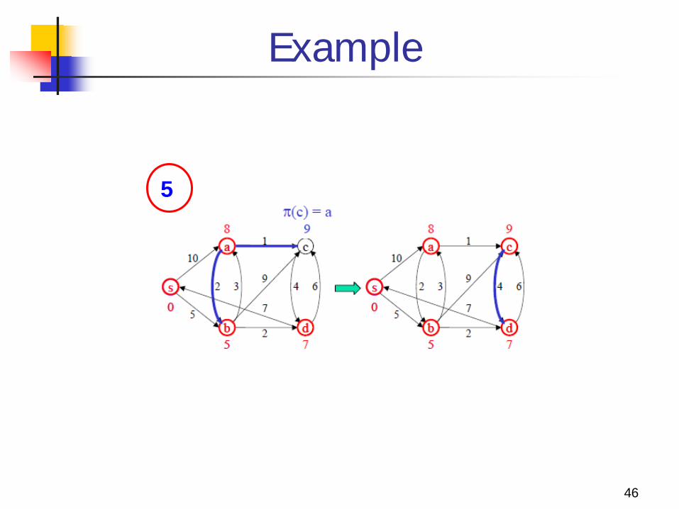
Example
46
5
47
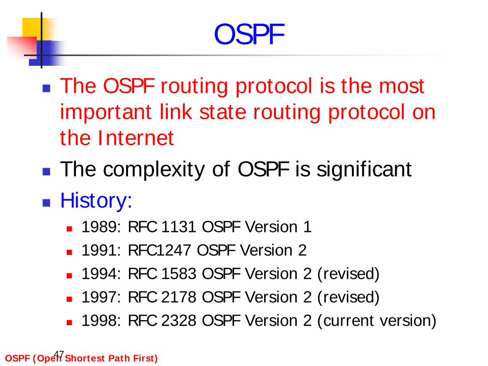
OSPF
The OSPF routing protocol is the most important link state routing protocol on the Internet
The complexity of OSPF is significant History:
1989: RFC 1131 OSPF Version 1 1991: RFC1247 OSPF Version 2 1994: RFC 1583 OSPF Version 2 (revised) 1997: RFC 2178 OSPF Version 2 (revised) 1998: RFC 2328 OSPF Version 2 (current version)
OSPF (Open Shortest Path First)
48
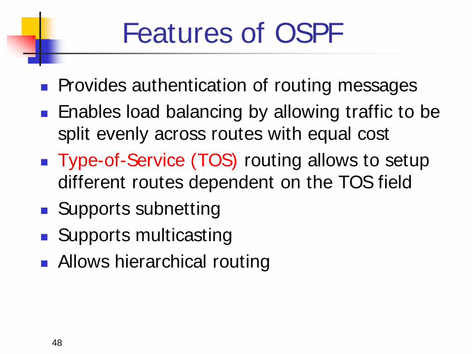
Features of OSPF
Provides authentication of routing messages Enables load balancing by allowing traffic to be
split evenly across routes with equal cost Type-of-Service (TOS) routing allows to setup
different routes dependent on the TOS field Supports subnetting Supports multicasting Allows hierarchical routing
49
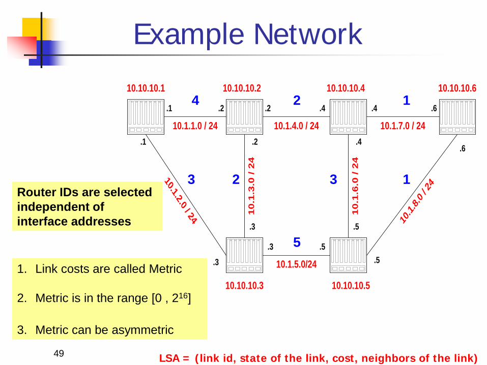
Example Network
10.1.1.0 / 24.1 .2 .2
10.10.10.1
10.1.4.0 / 24
10.1.2.0 / 24
.1
.4
10.1.7.0 / 24
10.1
.6.0
/ 2
4
10.1
.3.0
/ 2
410.1.5.0/24
10.1.
8.0 / 2
4
.3.3 .5
.2
.3
.5
.5
.4
.4
.6
.6
10.10.10.2 10.10.10.4 10.10.10.6
10.10.10.3 10.10.10.5
Router IDs are selected independent of interface addresses
3
4 2
5
1
1
3 2
1. Link costs are called Metric
2. Metric is in the range [0 , 216]
3. Metric can be asymmetric
LSA = (link id, state of the link, cost, neighbors of the link)
50
10.1.1.0 / 24.1 .2 .2
10.10.10.1
10.1.4.0 / 24
10.1.2.0 / 24
.1
10
.1.3
.0 /
24
10.1.5.0/24
.3
.3
.2
.3
10.10.10.2
10.10.10.3
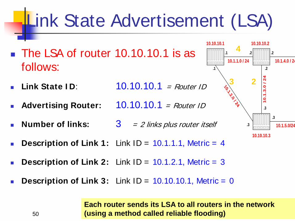
Link State Advertisement (LSA)
The LSA of router 10.10.10.1 is as follows:
Link State ID: 10.10.10.1 = Router ID
Advertising Router: 10.10.10.1 = Router ID
Number of links: 3 = 2 links plus router itself
Description of Link 1: Link ID = 10.1.1.1, Metric = 4
Description of Link 2: Link ID = 10.1.2.1, Metric = 3
Description of Link 3: Link ID = 10.10.10.1, Metric = 0
3
4
2
Each router sends its LSA to all routers in the network (using a method called reliable flooding)
51
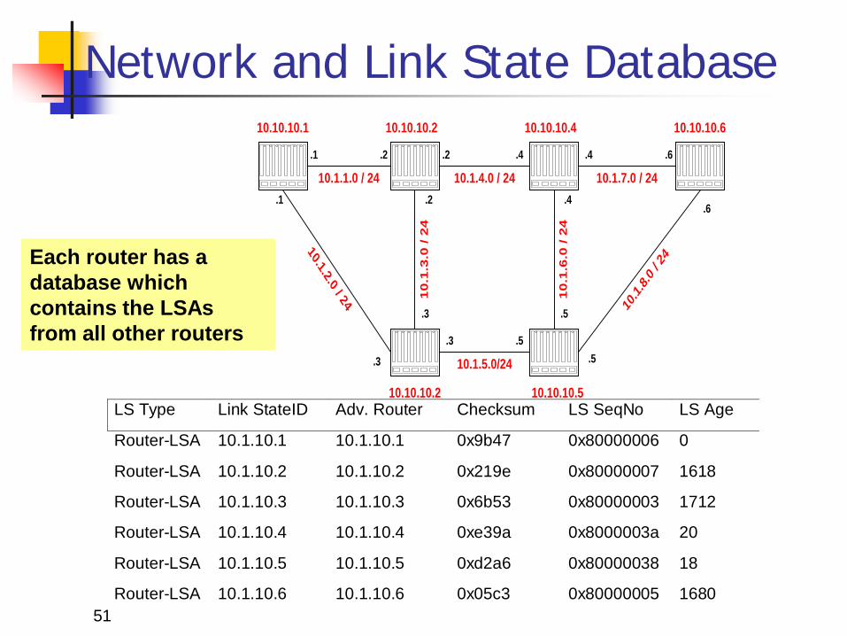
Network and Link State Database
10.1.1.0 / 24.1 .2 .2
10.10.10.1
10.1.4.0 / 24
10.1.2.0 / 24
.1
.4
10.1.7.0 / 24
10
.1.6
.0 /
24
10
.1.3
.0 /
24
10.1.5.0/24
10.1.
8.0 / 24
.3
.3 .5
.2
.3
.5
.5
.4
.4
.6
.6
10.10.10.2 10.10.10.4 10.10.10.6
10.10.10.2 10.10.10.5LS Type Link StateID Adv. Router Checksum LS SeqNo LS Age
Router-LSA 10.1.10.1 10.1.10.1 0x9b47 0x80000006 0
Router-LSA 10.1.10.2 10.1.10.2 0x219e 0x80000007 1618
Router-LSA 10.1.10.3 10.1.10.3 0x6b53 0x80000003 1712
Router-LSA 10.1.10.4 10.1.10.4 0xe39a 0x8000003a 20
Router-LSA 10.1.10.5 10.1.10.5 0xd2a6 0x80000038 18
Router-LSA 10.1.10.6 10.1.10.6 0x05c3 0x80000005 1680
Each router has a database which contains the LSAs from all other routers
52
Link State Database
The collection of all LSAs is called the link-state database
Each router has a identical link-state database Useful for debugging: Each router has a complete
description of the network
If neighboring routers discover each other for the first time, they will exchange their link-state databases
The link-state databases are synchronized using reliable flooding
53
OSPF Packet Format
OSPF MessageIP header
Body of OSPF MessageOSPF MessageHeader
Message TypeSpecific Data LSA LSALSA ...
LSAHeader
LSAData
...
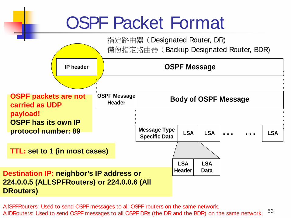
Destination IP: neighbor’s IP address or 224.0.0.5 (ALLSPFRouters) or 224.0.0.6 (All DRouters)
TTL: set to 1 (in most cases)
OSPF packets are not carried as UDP payload! OSPF has its own IP protocol number: 89
AllSPFRouters: Used to send OSPF messages to all OSPF routers on the same network. AllDRouters: Used to send OSPF messages to all OSPF DRs (the DR and the BDR) on the same network.
指定路由器(Designated Router, DR) 備份指定路由器(Backup Designated Router, BDR)
OSPF Packet Format
AllSPFRouters (224.0.0.5): Used to send OSPF messages to all OSPF routers on the same network.
The AllSPFRouters address is used for Hello packets. The designated router (DR) and backup designated
router (BDR) use this address to send Link State Update and Link State Acknowledgment packets.
AllDRouters (224.0.0.6): Used to send OSPF messages to all OSPF DRs (the DR and the BDR) on the same network.
All OSPF routers except the DR use this address to send Link State Update and Link State Acknowledgment packets to the DR.
54
55
OSPF Packet Format
source router IP address
authentication
authentication32 bits
version type message length
Area ID
checksum authentication type
Body of OSPF MessageOSPF MessageHeader
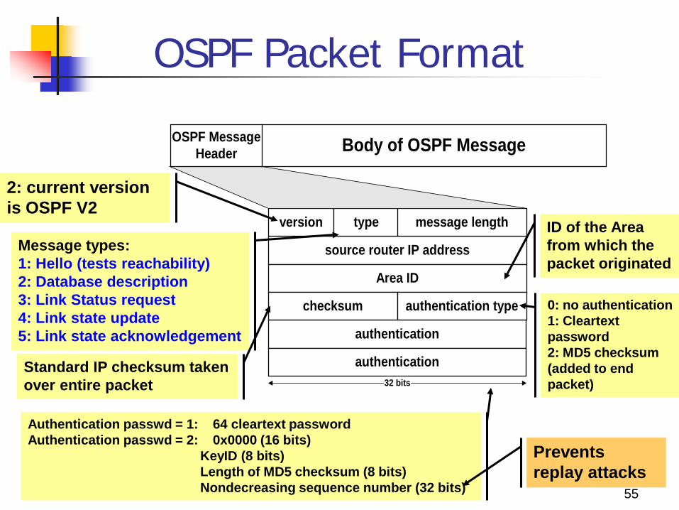
2: current version is OSPF V2
Message types: 1: Hello (tests reachability) 2: Database description 3: Link Status request 4: Link state update 5: Link state acknowledgement
ID of the Area from which the packet originated
Standard IP checksum taken over entire packet
0: no authentication 1: Cleartext password 2: MD5 checksum (added to end packet)
Authentication passwd = 1: 64 cleartext password Authentication passwd = 2: 0x0000 (16 bits) KeyID (8 bits) Length of MD5 checksum (8 bits) Nondecreasing sequence number (32 bits)
Prevents replay attacks
56
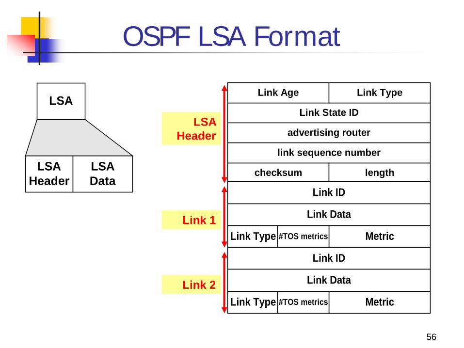
OSPF LSA Format
Link State ID
link sequence number
advertising router
Link Age Link Type
checksum length
Link ID
Link Data
Link Type Metric#TOS metrics
LSA
LSAHeader
LSAData
Link ID
Link Data
Link Type Metric#TOS metrics
LSA Header
Link 1
Link 2
57
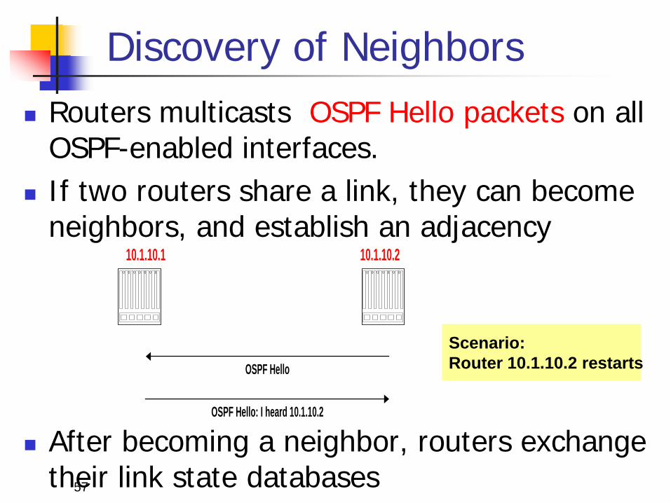
Discovery of Neighbors Routers multicasts OSPF Hello packets on all
OSPF-enabled interfaces. If two routers share a link, they can become
neighbors, and establish an adjacency
After becoming a neighbor, routers exchange their link state databases
OSPF Hello
OSPF Hello: I heard 10.1.10.2
10.1.10.1 10.1.10.2
Scenario: Router 10.1.10.2 restarts
58
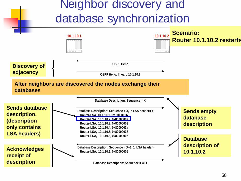
Neighbor discovery and database synchronization
OSPF Hello
OSPF Hello: I heard 10.1.10.2
Database Description: Sequence = X
10.1.10.1 10.1.10.2
Database Description: Sequence = X, 5 LSA headers = Router-LSA, 10.1.10.1, 0x80000006 Router-LSA, 10.1.10.2, 0x80000007 Router-LSA, 10.1.10.3, 0x80000003 Router-LSA, 10.1.10.4, 0x8000003a Router-LSA, 10.1.10.5, 0x80000038 Router-LSA, 10.1.10.6, 0x80000005
Database Description: Sequence = X+1, 1 LSA header= Router-LSA, 10.1.10.2, 0x80000005
Database Description: Sequence = X+1
Sends empty database description
Scenario: Router 10.1.10.2 restarts
Discovery of adjacency
Sends database description. (description only contains LSA headers)
Database description of 10.1.10.2 Acknowledges
receipt of description
After neighbors are discovered the nodes exchange their databases
59
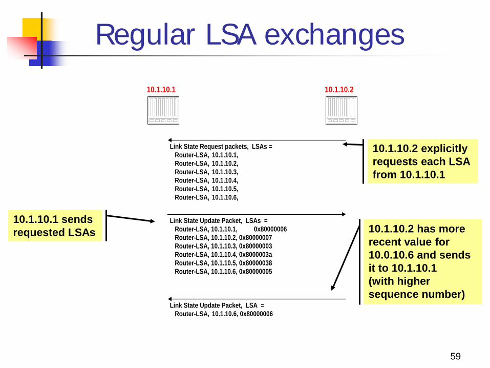
Regular LSA exchanges
10.1.10.1 10.1.10.2
Link State Request packets, LSAs = Router-LSA, 10.1.10.1, Router-LSA, 10.1.10.2, Router-LSA, 10.1.10.3, Router-LSA, 10.1.10.4, Router-LSA, 10.1.10.5, Router-LSA, 10.1.10.6,
Link State Update Packet, LSA = Router-LSA, 10.1.10.6, 0x80000006
Link State Update Packet, LSAs = Router-LSA, 10.1.10.1, 0x80000006 Router-LSA, 10.1.10.2, 0x80000007 Router-LSA, 10.1.10.3, 0x80000003 Router-LSA, 10.1.10.4, 0x8000003a Router-LSA, 10.1.10.5, 0x80000038 Router-LSA, 10.1.10.6, 0x80000005
10.1.10.2 explicitly requests each LSA from 10.1.10.1
10.1.10.1 sends requested LSAs 10.1.10.2 has more
recent value for 10.0.10.6 and sends it to 10.1.10.1 (with higher sequence number)
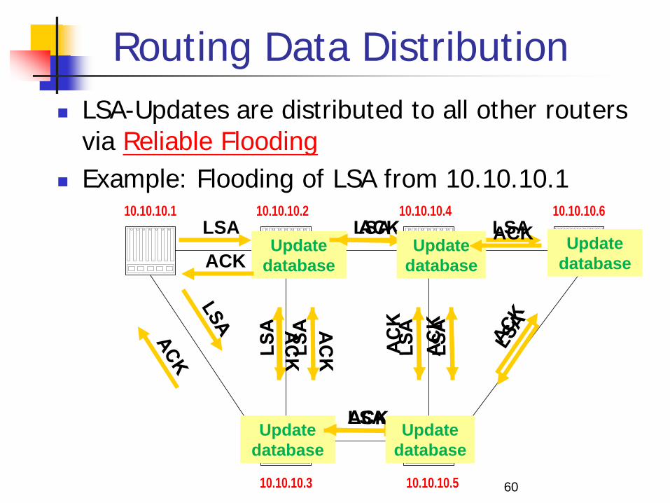
Routing Data Distribution LSA-Updates are distributed to all other routers
via Reliable Flooding Example: Flooding of LSA from 10.10.10.1
60
10.10.10.1 10.10.10.2 10.10.10.4 10.10.10.6
10.10.10.3 10.10.10.5
LSA Update
database
Update database
ACK
LSA
LSA LSA Update
database
Update database
ACK Update database
61
Dissemination of LSA-Update A router sends and refloods LSA-Updates, whenever
the topology or link cost changes. If a received LSA does not contain new information, the router
will not flood the packet.
Period change information: Infrequently (every 30 minutes), a router will flood LSAs even if there are not new changes.
Acknowledgements of LSA-updates: explicit ACK, or implicit via reception of an LSA-Update
62
Autonomous Systems An autonomous system is a region of the
Internet that is administered by a single entity. Examples of autonomous regions are:
campus network backbone network Regional Internet Service Provider
Routing is done differently within an autonomous system (intradomain routing) and between autonomous system (interdomain routing).
63
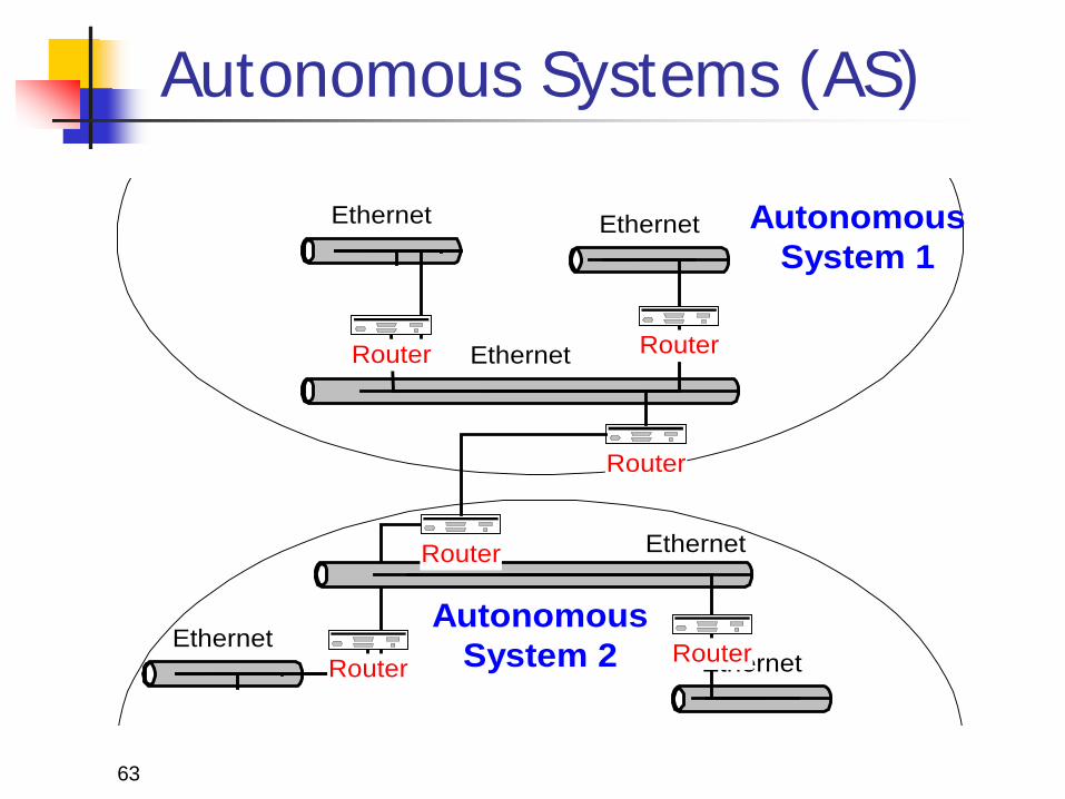
Autonomous Systems (AS)
Ethernet
Router
Ethernet
Ethernet
RouterRouter
Ethernet
Ethernet
EthernetRouterRouter
Router
AutonomousSystem 2
AutonomousSystem 1
64
Border Gateway Protocol (BGP) Currently in version 4 Note: In the context of BGP, a gateway is nothing else
but an IP router that connects autonomous systems. Interdomain routing protocol is used for routing
between autonomous systems Uses TCP to send routing messages
BGP is neither a link state, nor a distance vector protocol.
Routing messages in BGP contain complete routes. Network administrators can specify routing policies
65
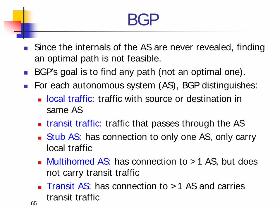
BGP Since the internals of the AS are never revealed, finding
an optimal path is not feasible. BGP’s goal is to find any path (not an optimal one). For each autonomous system (AS), BGP distinguishes:
local traffic: traffic with source or destination in same AS
transit traffic: traffic that passes through the AS Stub AS: has connection to only one AS, only carry
local traffic Multihomed AS: has connection to >1 AS, but does
not carry transit traffic Transit AS: has connection to >1 AS and carries
transit traffic
66
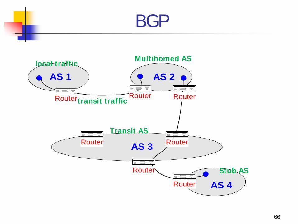
BGP
AS 1 AS 2
AS 3Router
AS 4
RouterRouter Router
Router
Router
Router
local traffic
transit traffic
Stub AS
Multihomed AS
Transit AS
OSPF area: composed of routers and hosts. Area 0 represents backbone area. OSPF must have an area 0. All areas have to connect with backbone area, and the
all routes of same area are shared in this area. One router can belong to one or more areas.
The all routes of same area have same topology; OSPF area are composed of the areas.
Using the area of hierarchy architecture: only effect on self-area, fast convergence, scalable, robust.
67
OSPF
OSPF Hierarchy architecture:
backbone router: the router of area 0 internal router: the inner routers of same area ABR(area broder router): each interface connects to different
areas, but at least one interface connects with area 0. ASBR(autonomous system border router): connect with other
as, and imports other as’s (Autonomous System) routing information into own OSPF.
Advantage: confine network instability to an area(可將網路的不穩定性限制
在一區域內) speed up convergence decrease routing overhead improve performance
Disadvantage: Design complexity. 68
OSPF to the Edge Design Recommendations
Configure each distribution block as a separate totally stubby OSPF area.
The distribution switches become Area Border Routers (ABRs) with their core-facing interfaces in area 0 and the access layer interfaces in unique totally stubby areas for each access layer switch.
Each access layer switch is configured into its own unique totally stubby area.
Link-state advertisements (LSAs) are isolated to each access layer switch, so that a link flap for one access layer switch is not communicated beyond the distribution pairs.
69
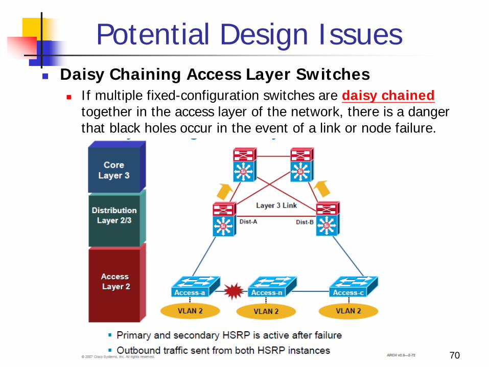
Potential Design Issues Daisy Chaining Access Layer Switches
If multiple fixed-configuration switches are daisy chained together in the access layer of the network, there is a danger that black holes occur in the event of a link or node failure.
70
Potential Design Issues
Both distribution nodes can forward traffics from the rest of the network towards the access layer.
If a link or node in the middle of the chain or stack fails, two scenarios can occur 1. First case, the standby HSRP peer can go active as
it loses connectivity to its primary peer, forwarding traffic outbound for the devices that still have connectivity to it.
2. The primary HSRP peer remains active and also forwards outbound traffic for its half of the stack. It is also not detrimental from the perspective of outbound traffic.
71
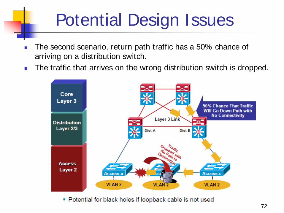
Potential Design Issues The second scenario, return path traffic has a 50% chance of
arriving on a distribution switch. The traffic that arrives on the wrong distribution switch is dropped.
72
Potential Design Issues
The solution is to provide alternate connectivity across the stack in the form of a loop-back cable running from the top to the bottom of the stack. This link needs to be carefully deployed so the
appropriate STP behavior will occur in the access layer.
An alternate design uses a Layer 2 link between the
distribution switches.
73
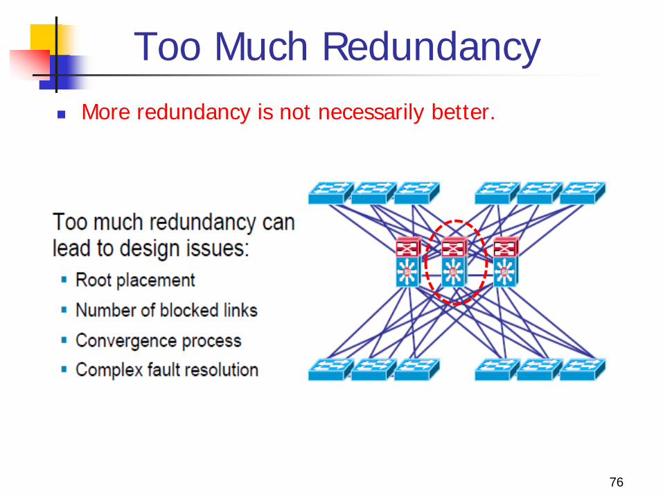
Too Much Redundancy More redundancy is not necessarily better.
76
Added a New Switch A third switch is added to the distribution switches in
the center. This extra switch adds unneeded complexity to the
design and leads to design questions: Where should the root switch be placed?
With this design, it is not easy to determine where the root switch is located.
What links should be in a blocking state? It is very hard to determine how many ports will be in a
blocking state. What are the implications of STP/RSTP convergence?
The network convergence is definitely not deterministic. When something goes wrong, how do you find the source of
the problem? The design is much harder to troubleshoot. 77
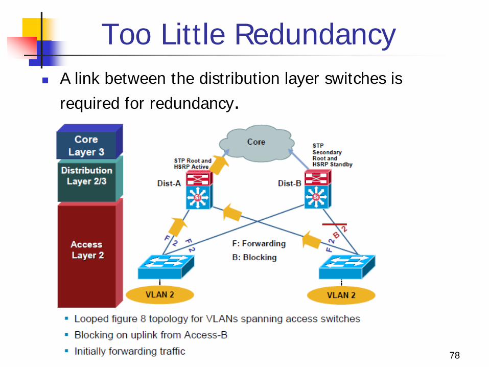
Too Little Redundancy A link between the distribution layer switches is
required for redundancy.
78
Without a Layer 2 Link
Without a Layer 2 link between the distribution switches, the design is a looped topology.
One access layer uplink will be blocking. HSRP hellos are exchanged by transiting the access switches.
Initially traffic is forwarded from both access switches to Dist-A switch which supports the STP root and the HSRP primary for VLAN 2.
However, this design will black hole traffic and be affected by multiple convergence events with a single network failure.
79
Example: Impact of an Uplink Failure
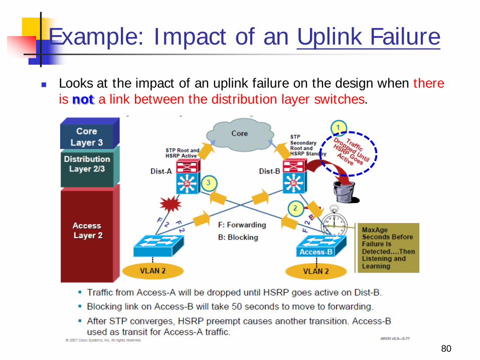
Looks at the impact of an uplink failure on the design when there is not a link between the distribution layer switches.
80
Impact of an Uplink Failure
When the uplink from Access-A to the Dist-A fails there are three convergence events:
1. Access-A sends traffic across its active uplink to Dist-B to get to its default gateway. 1. The traffic is black holed at Dist-B because Dist-B does not initially have a
path to HSRP primary on Dist-A due to the STP blocking. 2. The traffic is dropped until the standby HSRP peer takes over as the default
gateway after not receiving HSRP hellos from Dist-A.
2. The indirect link failure is eventually detected by Access-B after the MaxAge timer expires, and Access-B removes blocking on the uplink to Dist-B. 1. With standard STP, transitioning to forwarding can take as long as 50
seconds. If BackboneFast is enabled with Per VLAN Spanning Tree + (PVST+), this
time can be reduced to 30 seconds, and RSTP can reduce this interval to as little as one second.
81
Impact of an Uplink Failure
3. After STP/RSTP converges, the distribution nodes reestablish their HSRP relationships and the Dist-A, the primary HSRP peer, preempts.
4. This causes yet another convergence event when Access-A end points start forwarding traffic to the primary HSRP peer. The Access-A traffic goes through Access-B to reach its
default gateway.
5. The Access-B uplink to Dist-B is now a transit link for Access-A traffic, and the Access-B uplink to Dist-A must now carry traffic for both the originally intended Access-B and for Access-A.
82
Impact on Return Path Traffic
83
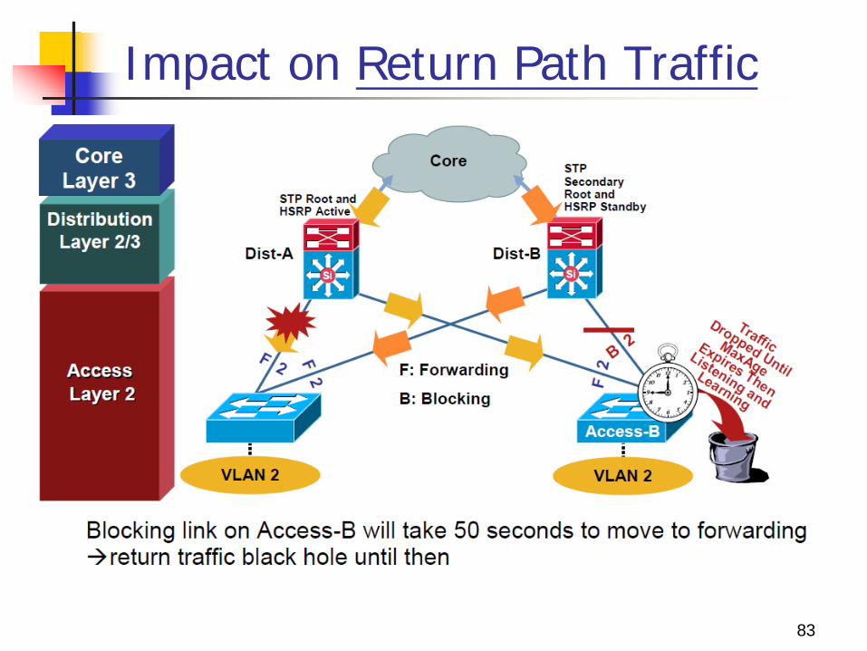
Impact on Return Path Traffic
This indirect link failure convergence can take as long as 50 seconds. PVST+ with UplinkFast reduces the time to 3 to 5 seconds, and
RSTP further reduces the outage to one second.
After the STP/RSTP convergence, the Access-B uplink to Dist-B is used as a transit link for Access-A return path traffic.
These significant outages could affect the performance of mission-critical applications such as voice or video.
84
Impact on Return Path Traffic
Both outbound and return path traffic are difficult and complex, and must support the traffic for at least one additional access layer switch.
The conclusion is that if VLANs must span the access switches, a Layer 2 link is needed either between the distribution layer switches or the access switches.
85
Asymmetric Routing (Unicast Flooding)
86
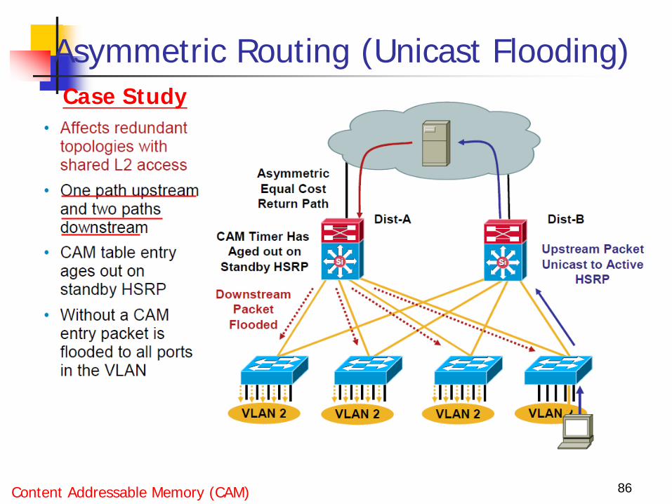
Case Study
Content Addressable Memory (CAM)
Asymmetric Routing (Unicast Flooding)
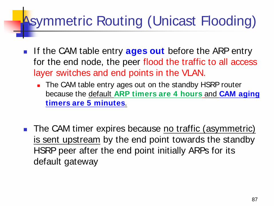
If the CAM table entry ages out before the ARP entry for the end node, the peer flood the traffic to all access layer switches and end points in the VLAN. The CAM table entry ages out on the standby HSRP router
because the default ARP timers are 4 hours and CAM aging timers are 5 minutes.
The CAM timer expires because no traffic (asymmetric)
is sent upstream by the end point towards the standby HSRP peer after the end point initially ARPs for its default gateway
87
Asymmetric Routing (Unicast Flooding)
The majority of the access layer switches also do not have a CAM entry for the target MAC, and they also broadcast the return traffic on all ports in the common VLAN.
This unicast traffic flooding can have a significant performance impact on the connected end stations because they may receive a large amount of traffic that is not intended for them.
88
Unicast Flooding Prevention
89
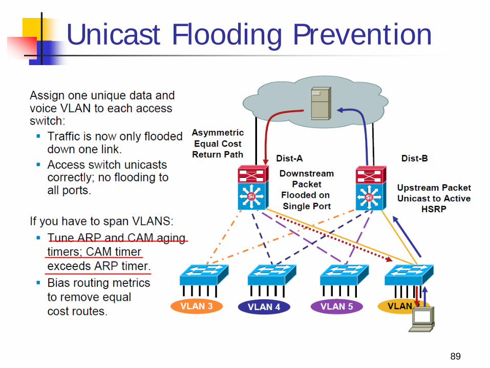
Unicast Flooding Prevention
Unicast flooding is not an issue when VLANs are not present across multiple access layer switches because the flooding occurs only to switches supporting the VLAN where the traffic would have normally been switched.
If the VLANs are local to individual access layer switches, asymmetric routing traffic is only flooded on the one interface in the VLAN on the distribution switch.
Additionally, the access layer switch receiving the flooded traffic has a CAM table entry for the host because the host is directly attached, so traffic is switched only to the intended host.
90
Case1:
Unicast Flooding Prevention
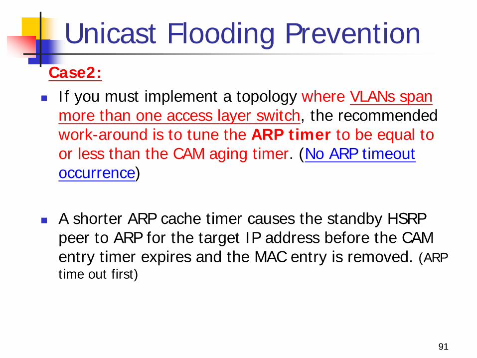
If you must implement a topology where VLANs span more than one access layer switch, the recommended work-around is to tune the ARP timer to be equal to or less than the CAM aging timer. (No ARP timeout occurrence)
A shorter ARP cache timer causes the standby HSRP peer to ARP for the target IP address before the CAM entry timer expires and the MAC entry is removed. (ARP time out first)
91
Case2:
Summary
Layer 2 to Layer 3 boundary design has three models: Layer 2 distribution switch interconnection Layer 3 distribution switch interconnection Layer 3 access to distribution switch interconnection
There are a few potential design issues with the layered model: Daisy chaining access layer switches Too much redundancy Too little redundancy Asymmetric flooding
92


![Effect of Boundary Misorientation on Yielding Behavior of … · 2017. 3. 30. · Fig. 1: (a) The tiling of layer unit [BAb] and (b) of layer unit [C2C1C2i]. The double circles indicate](https://img.pdfslide.tips/doc/110x75/6129c8c160b3c5209737874f/effect-of-boundary-misorientation-on-yielding-behavior-of-2017-3-30-fig-1.jpg)