Embed Size (px)
Citation preview
1
Chapter 4
Layer 2 to Layer 3 Boundary Design
Objectives
Designs to support the Layer 2 to Layer 3 boundary in enterprise campus networks.
Includes being able to meet these objectives: Describe and select the appropriate Layer 2 to Layer
3 boundary design models Describe and avoid potential design issues with the
design models
2
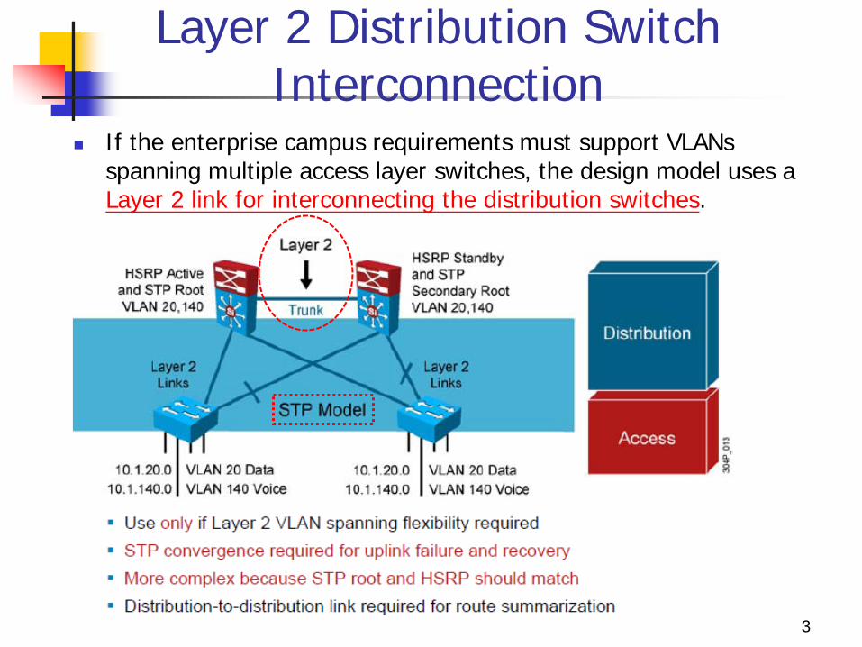
Layer 2 Distribution Switch Interconnection
If the enterprise campus requirements must support VLANs spanning multiple access layer switches, the design model uses a Layer 2 link for interconnecting the distribution switches.
3
Layer 2 Distribution Switch Interconnection
This design is more complex than the Layer 3 interconnection of the distribution switches.
The Spanning Tree Protocol (STP) convergence process will be initiated for uplink failures and recoveries.
You should take the following steps to improve this suboptimal design:
1. Must to use Rapid STP (RSTP). 2. Provide a Layer 2 trunk between the two distribution
switches to avoid unexpected traffic paths and multiple convergence events.
4
Layer 2 Distribution Switch Interconnection
3. If you choose to load-balance VLANs across uplinks, be sure to place the Hot Standby Router Protocol (HSRP) primary and the STP primary on the same distribution layer switch.
4. The HSRP and RSTP root should be collocated on the same distribution switches to avoid using the interdistribution link for transit.
5
Layer 3 Distribution Switch Interconnection
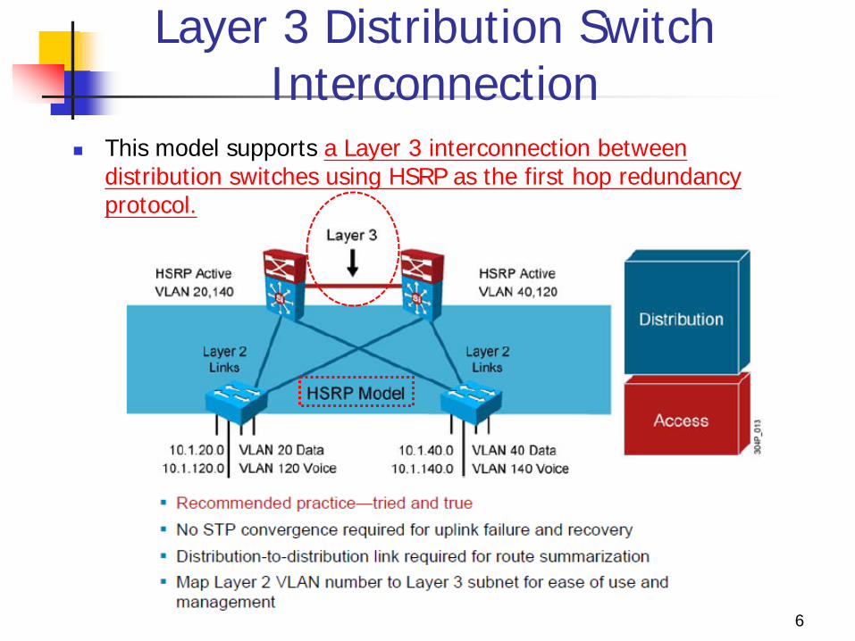
This model supports a Layer 3 interconnection between distribution switches using HSRP as the first hop redundancy protocol.
6
HSRP
Hot Standby Router Protocol (HSRP) is a Cisco proprietary redundancy protocol. for establishing a fault-tolerant default gateway, and has been
described in detail in RFC 2281.
The protocol establishes a framework between network routers in
order to achieve default gateway failover. if the primary gateway becomes inaccessible, in close association with
a rapid-converging routing protocol like EIGRP or OSPF.
By multicasting packets, HSRP sends its hello messages to
the multicast address 224.0.0.2 (all routers) for version 1, or 224.0.0.102 for version 2, using UDP port 1985, to other HSRP-enabled routers, defining priority between the routers.
7
HSRP
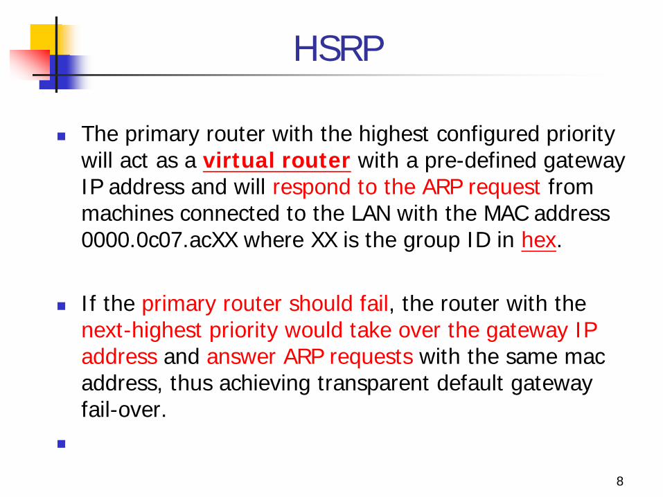
The primary router with the highest configured priority will act as a virtual router with a pre-defined gateway IP address and will respond to the ARP request from machines connected to the LAN with the MAC address 0000.0c07.acXX where XX is the group ID in hex.
If the primary router should fail, the router with the next-highest priority would take over the gateway IP address and answer ARP requests with the same mac address, thus achieving transparent default gateway fail-over.
8
Layer 3 Distribution Switch Interconnection
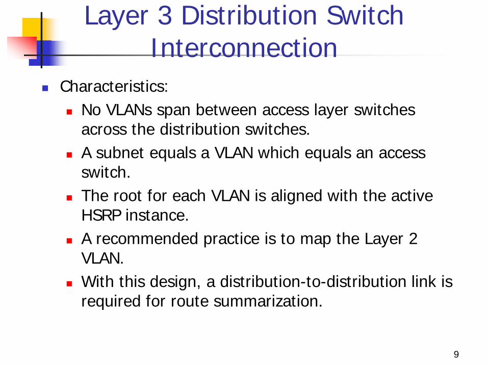
Characteristics: No VLANs span between access layer switches
across the distribution switches. A subnet equals a VLAN which equals an access
switch. The root for each VLAN is aligned with the active
HSRP instance. A recommended practice is to map the Layer 2
VLAN. With this design, a distribution-to-distribution link is
required for route summarization.
9
GLBP
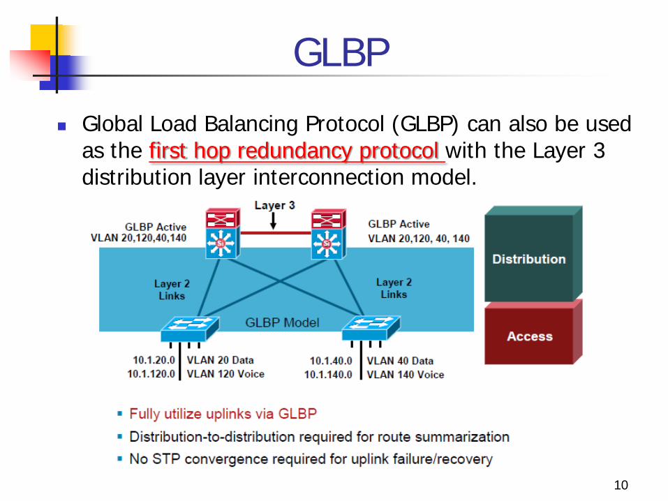
Global Load Balancing Protocol (GLBP) can also be used as the first hop redundancy protocol with the Layer 3 distribution layer interconnection model.
10
GLBP
GLBP allows full utilize of the uplinks from the access layer.
The distribution to distribution link is still required for route summarization.
Since the VLANs do not span access switches, STP convergence is not required for uplink failure and recovery.
11
GLBP GLBP is a first-hop redundancy protocol designed by Cisco that
allows packet load sharing among groups of redundant routers. HSRP or VRRP is used to provide default-gateway redundancy, the
backup members of the peer relationship are idle. waiting for a failure event to occur before they take over and actively forward
traffic.
Another technique uses multiple HSRP groups on a single interface and uses DHCP to alternate between the multiple default gateways. These techniques work but are not optimal from a configuration, maintenance,
or management perspective.
GLBP provides all the benefits of HSRP and includes load balancing, too.
12
Example
13
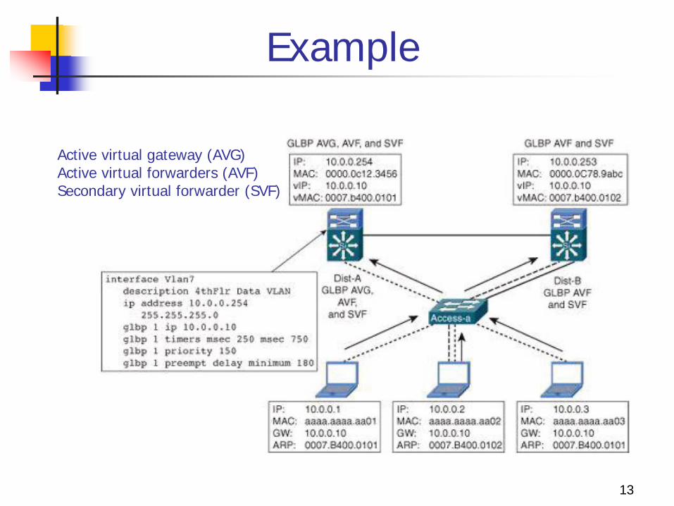
Active virtual gateway (AVG) Active virtual forwarders (AVF) Secondary virtual forwarder (SVF)
GLBP Advantage:
1. allows for the automatic selection and simultaneous use of multiple available gateways as well as automatic failover between those gateways
2. none of the clients has to be pointed toward a specific gateway address; they can all have the same default gateway set to the virtual router IP address.
Principle : Single virtual IP address and multiple virtual MAC addresses 1. As a client sends an ARP request looking for the virtual router
IP address, 2. GLBP sends back an ARP reply with the virtual MAC address of
a selected router in the group. 3. The result is that all clients use the same gateway IP address
but have differing MAC addresses for it.
14
Layer 3 Access to Distribution Interconnection
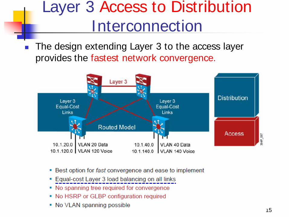
The design extending Layer 3 to the access layer provides the fastest network convergence.
15
Layer 3 Access to Distribution Interconnection
A routing protocol such as EIGRP, when properly tuned, can achieve better convergence results than designs that rely on STP to resolve convergence events.
A routing protocol can even achieve better convergence results than the time-tested design placing the Layer 2 to Layer 3 boundary at the distribution layer.
The design is easier to implement than configuring Layer 2 in the distribution layer because you do not need to align STP with HSRP or GLBP.
This design supports equal-cost Layer 3 load balancing on all links between the network switches.
16
Layer 3 Access to Distribution Interconnection
No HSRP or GLBP configuration. VLANs can not span access switches in this design.
However, some additional complexity associated with uplink IP addressing and subnetting as well as the loss of flexibility are associated with this design alternative.
17
4 Feb 2008 LSNDI RMRA 18
Enhanced Interior Gateway Protocol (EIGRP)
Released in 1994 as successor to IGRP and compatible with IGRP.
Hybrid routing protocol with best of distance vector algorithms.
Uses partial updates and neighbor discovery. Like OSPF but easier to configure. Good for large multiprotocol networks that
primarily use Cisco routers.
4 Feb 2008 LSNDI RMRA 19
EIGRP key features
EIGRP automatically shares routing information with IGRP and vice versa
Rapid convergence from Diffused Updating Algorithm (DUAL)
Guaranteed no loops – all routers running EIGRP update at the same time if change occurs
Efficient use of BW – partial incremental updates only Sent only to routers that need information – not all
routers
4 Feb 2008 LSNDI RMRA 20
EIGRP key features
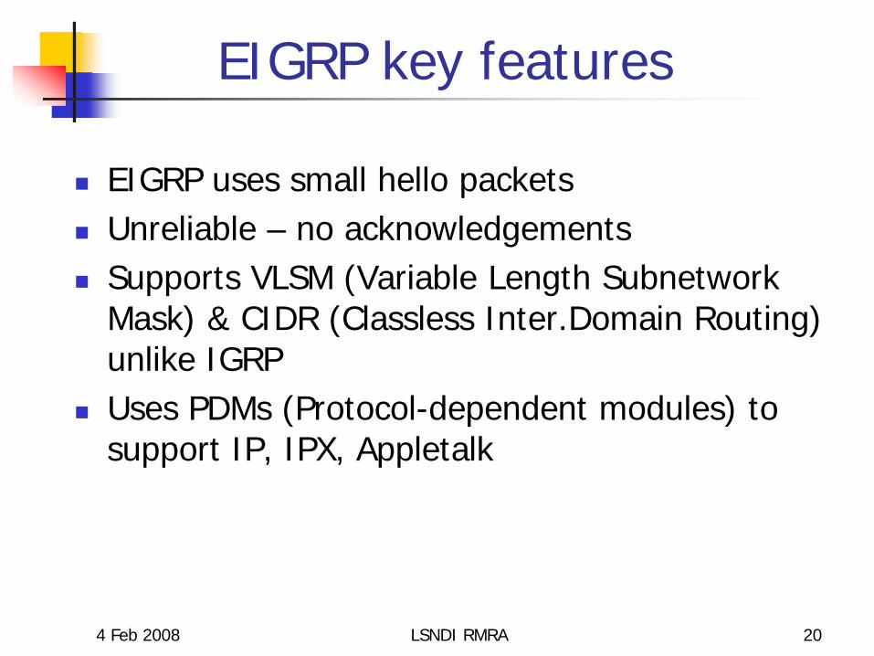
EIGRP uses small hello packets Unreliable – no acknowledgements Supports VLSM (Variable Length Subnetwork
Mask) & CIDR (Classless Inter.Domain Routing) unlike IGRP
Uses PDMs (Protocol-dependent modules) to support IP, IPX, Appletalk
25
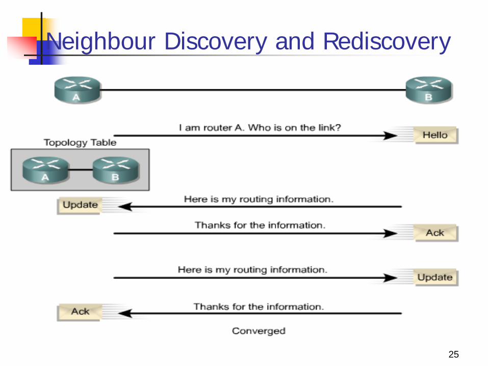
Neighbour Discovery and Rediscovery
EIGRP to the Edge Design Recommendations
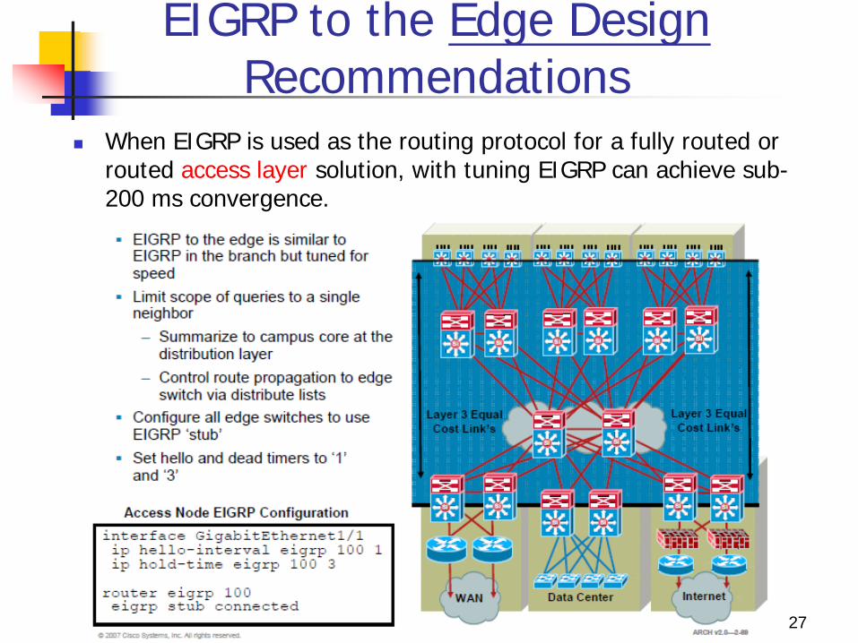
When EIGRP is used as the routing protocol for a fully routed or routed access layer solution, with tuning EIGRP can achieve sub-200 ms convergence.
27
EIGRP to the Edge Design Recommendations
This confines impact of an individual access link failure to the distribution pair by stopping EIGRP queries from propagating beyond the core of the network.
Configure all edge switches to use EIGRP stub, so the edge devices are not queried by the distribution switches for routes. EIGRP stub nodes are not able to act as transit nodes and do not participate in EIGRP query processing.
When the distribution node learns through the EIGRP hello packets that it is talking to a stub node, it does not flood queries to that node.
28
EIGRP to the Edge Design Recommendations
Control route propagation to edge switches using distribute lists. The access switches only need a default route to the distribution switches.
An outbound distribute list applied to all interfaces facing the access layer from the distribution switch will conserve memory and optimize performance at the access layer.
29

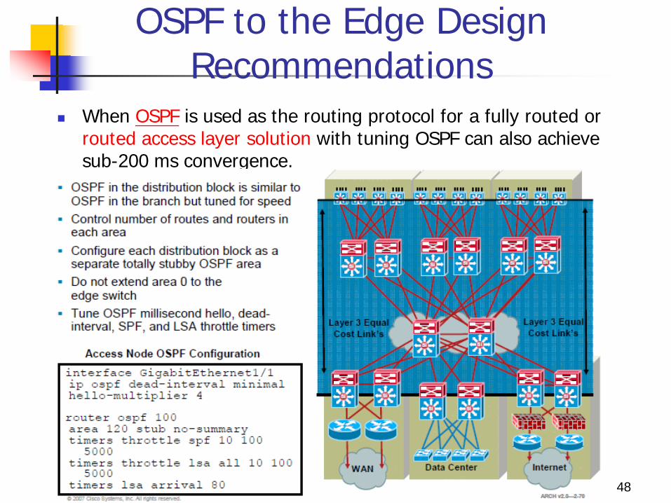
OSPF to the Edge Design Recommendations
When OSPF is used as the routing protocol for a fully routed or routed access layer solution with tuning OSPF can also achieve sub-200 ms convergence.
30
OSPF Operation
Every OSPF router sends out 'hello' packets. Hello packets used to determine if neighbor is up. Hello packets are small easy to process packets. Hello packets are sent periodically (usually short interval).
OSPF Operation
Once an adjacency is established, trade information with your neighbor. Topology information is packaged in a "link state announcement“ Announcements are sent ONCE, and only updated if there's a change (or time out) Note 1. Change occurs 2. Broadcast change 3. Run shortest path tree (SPF) algorithm 4. Install output into forwarding table
Neighbor
Bi-directional OSPF communication Result of OSPF hello packets Need not exchange routing information
Adjacency
Between OSPF neighbors Exchange routing information Point-to-point or Broadcast media
Point-to-point - neighbors are adjacent Broadcast media - not all neighbors are adjacent
14
Broadcast Media
Select a neighbor - Designated Router(DR) All routers become adjacent to DR Exchange routing information with the DR DR updates all the neighbors Backup Designated Router
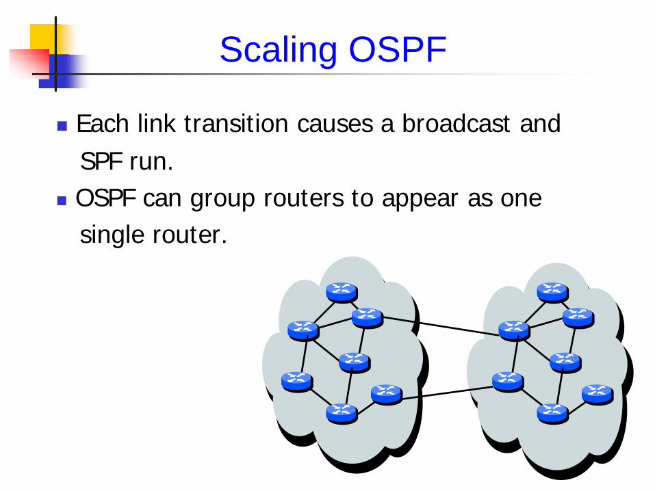
Scaling OSPF
Each link transition causes a broadcast and SPF run. OSPF can group routers to appear as one single router.
Scaling OSPF
Rule of thumb: no more than 150 routers/area Reality: no more than 500 routers/area Proper use of areas can reduce bandwidth and increase CPU utilization. Instability is limited within each area Divide and conquer
OSPF to the Edge Design Recommendations
When OSPF is used as the routing protocol for a fully routed or routed access layer solution with tuning OSPF can also achieve sub-200 ms convergence.
48
OSPF area: composed of routers and hosts. Area 0 represents backbone area. OSPF must have an area 0. All areas have to connect with backbone area, and the
all routes of same area are shared in this area. One router can belong to one or more areas.
The all routes of same area have same topology; OSPF area are composed of the areas.
Using the area of hierarchy architecture: only effect on self-area, fast convergence, scalable, robust.
49
OSPF
OSPF Hierarchy architecture:
backbone router: the router of area 0 internal router: the inner routers of same area ABR(area broder router): each interface connects to different
areas, but at least one interface connects with area 0. ASBR(autonomous system border router): connect with other
as, and imports other as’s (Autonomous System) routing information into own OSPF.
Advantage: confine network instability to an area(可將網路的不穩定性限制
在一區域內) speed up convergence decrease routing overhead improve performance
Disadvantage: Design complexity. 50
OSPF to the Edge Design Recommendations
Configure each distribution block as a separate totally stubby OSPF area. The distribution switches become Area Border Routers (ABRs) with their core-facing interfaces in area 0 and the access layer interfaces in unique totally stubby areas for each access layer switch.
Each access layer switch is configured into its own unique totally stubby area. Link-state advertisements (LSAs) are isolated to each access layer switch, so that a link flap for one access layer switch is not communicated beyond the distribution pairs.
51
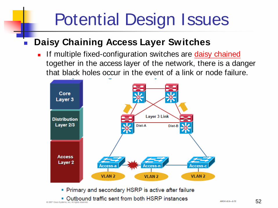
Potential Design Issues Daisy Chaining Access Layer Switches
If multiple fixed-configuration switches are daisy chained together in the access layer of the network, there is a danger that black holes occur in the event of a link or node failure.
52
Potential Design Issues
Both distribution nodes can forward traffics from the rest of the network towards the access layer.
Two scenarios can occur if a link or node in the middle of the chain or stack fails. 1. First case, the standby HSRP peer can go active as
it loses connectivity to its primary peer, forwarding traffic outbound for the devices that still have connectivity to it.
2. The primary HSRP peer remains active and also forwards outbound traffic for its half of the stack. It is also not detrimental from the perspective of outbound traffic.
53
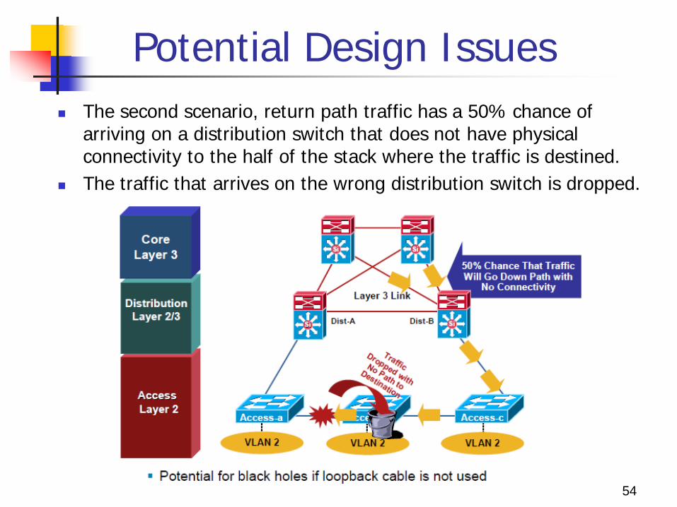
Potential Design Issues The second scenario, return path traffic has a 50% chance of
arriving on a distribution switch that does not have physical connectivity to the half of the stack where the traffic is destined.
The traffic that arrives on the wrong distribution switch is dropped.
54
Potential Design Issues
The solution is to provide alternate connectivity across the stack in the form of a loop-back cable running from the top to the bottom of the stack. This link needs to be carefully deployed so the
appropriate STP behavior will occur in the access layer.
An alternate design uses a Layer 2 link between the
distribution switches.
55
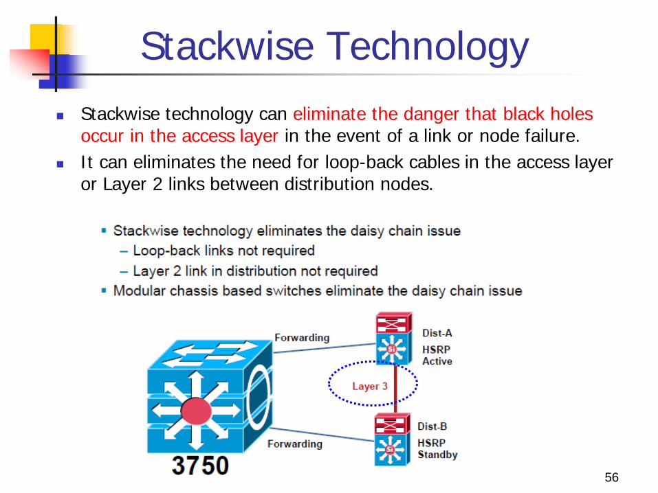
Stackwise Technology Stackwise technology can eliminate the danger that black holes
occur in the access layer in the event of a link or node failure. It can eliminates the need for loop-back cables in the access layer
or Layer 2 links between distribution nodes.
56
Stackwise Technology
StackWise technology in the access layer uses a Layer 3 connection between the distribution switches without having to use a loop-back cable or perform extra configuration.
The true stack creation provided by the Cisco Catalyst 3750 Series switches makes using stacks in the access layer much less complex than chains or stacks of other models.
57
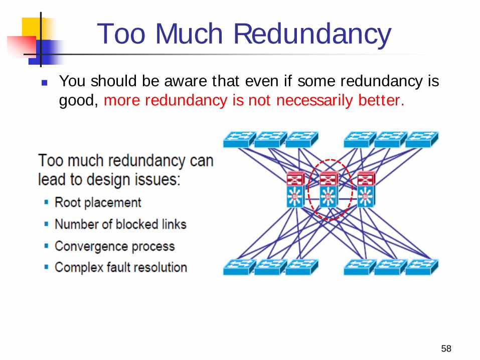
Too Much Redundancy You should be aware that even if some redundancy is
good, more redundancy is not necessarily better.
58
Too Much Redundancy
A third switch is added to the distribution switches in the center. This extra switch adds unneeded complexity to the design and leads to design questions: Where should the root switch be placed? With this design, it is
not easy to determine where the root switch is located. What links should be in a blocking state? It is very hard to
determine how many ports will be in a blocking state. What are the implications of STP/RSTP convergence? The
network convergence is definitely not deterministic. When something goes wrong, how do you find the source of
the problem? The design is much harder to troubleshoot.
59
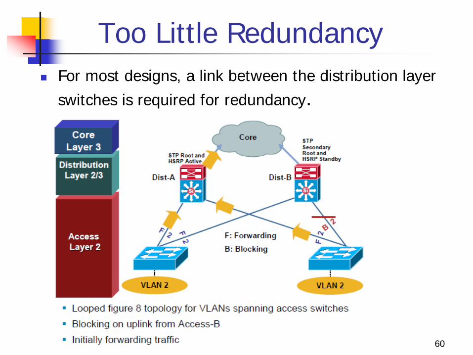
Too Little Redundancy For most designs, a link between the distribution layer
switches is required for redundancy.
60
Too Little Redundancy
Without a Layer 2 link between the distribution switches, the design is a looped figure 8 topology. One access layer uplink will be blocking. HSRP hellos are exchanged by transiting the access switches.
Initially traffic is forwarded from both access switches to Dist-A switch which supports the STP root and the HSRP primary for VLAN 2.
However, this design will black hole traffic and be affected by multiple convergence events with a single network failure.
61
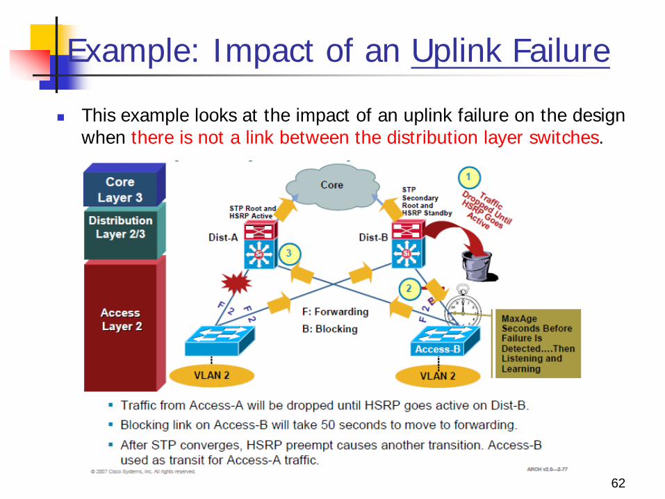
Example: Impact of an Uplink Failure
This example looks at the impact of an uplink failure on the design when there is not a link between the distribution layer switches.
62
Impact of an Uplink Failure
When the uplink from Access-A to the Dist-A fails there are three convergence events:
1. Access-A sends traffic across its active uplink to Dist-B to get to its default gateway. 1. The traffic is black holed at Dist-B because Dist-B does not initially have a
path to HSRP primary on Dist-A due to the STP blocking. 2. The traffic is dropped until the standby HSRP peer takes over as the default
gateway after not receiving HSRP hellos from Dist-A.
2. The indirect link failure is eventually detected by Access-B after the MaxAge timer expires, and Access-B removes blocking on the uplink to Dist-B. 1. With standard STP, transitioning to forwarding can take as long as 50
seconds. If BackboneFast is enabled with Per VLAN Spanning Tree + (PVST+), this time can be reduced to 30 seconds, and RSTP can reduce this interval to as little as one second.
63
Impact of an Uplink Failure
3. After STP/RSTP converges, the distribution nodes reestablish their HSRP relationships and the Dist-A, the primary HSRP peer, preempts.
4. This causes yet another convergence event when Access-A end points start forwarding traffic to the primary HSRP peer. The unexpected side effect is that Access-A traffic goes through Access-B to reach its default gateway.
5. The Access-B uplink to Dist-B is now a transit link for Access-A traffic, and the Access-B uplink to Dist-A must now carry traffic for both the originally intended Access-B and for Access-A.
64
Impact on Return Path Traffic
65
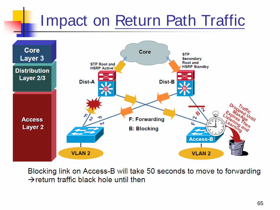
Impact on Return Path Traffic
This indirect link failure convergence can take as long as 50 seconds.
PVST+ with UplinkFast reduces the time to 3 to 5 seconds, and RSTP further reduces the outage to one second.
After the STP/RSTP convergence, the Access-B uplink to Dist-B is used as a transit link for Access-A return path traffic.
These significant outages could affect the performance of mission-critical applications such as voice or video.
66
Impact on Return Path Traffic
Both outbound and return path traffic are difficult and complex, and must support the traffic for at least one additional access layer switch.
The conclusion is that if VLANs must span the access switches, a Layer 2 link is needed either between the distribution layer switches or the access switches.
67
Asymmetric Routing (Unicast Flooding)
68
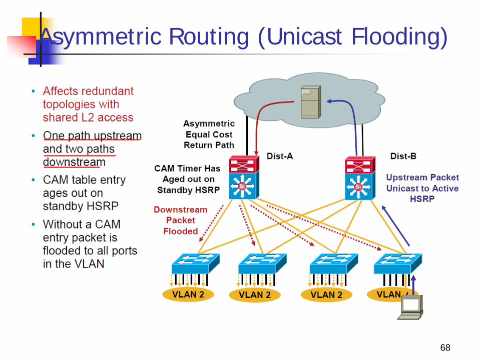
Asymmetric Routing (Unicast Flooding)
If the CAM table entry ages out before the ARP entry for the end node, the peer may need to flood the traffic to all access layer switches and end points in the VLAN.
The CAM table entry ages out on the standby HSRP router because the default ARP timers are 4 hours and CAM aging timers are 5 minutes.
The CAM timer expires because no traffic is sent upstream by the end point towards the standby HSRP peer after the end point initially ARPs for its default gateway
69
Asymmetric Routing (Unicast Flooding)
The majority of the access layer switches also do not have a CAM entry for the target MAC, and they also broadcast the return traffic on all ports in the common VLAN.
This unicast traffic flooding can have a significant performance impact on the connected end stations because they may receive a large amount of traffic that is not intended for them.
70
Unicast Flooding Prevention
71
Unicast Flooding Prevention
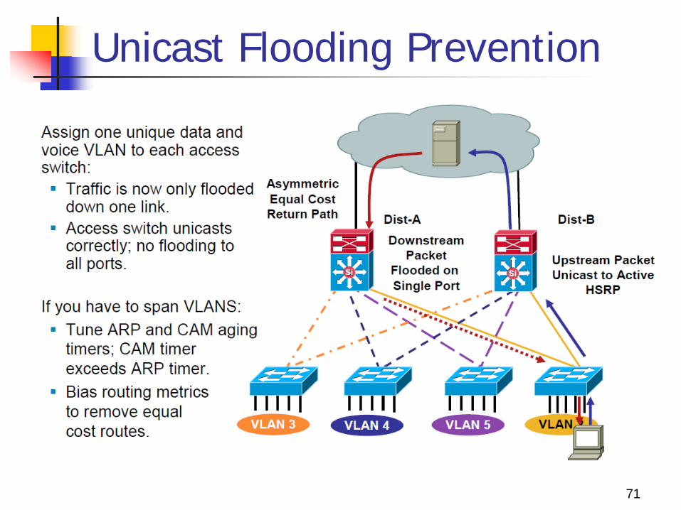
Unicast flooding is not an issue when VLANs are not present across multiple access layer switches because the flooding occurs only to switches supporting the VLAN where the traffic would have normally been switched.
If the VLANs are local to individual access layer switches, asymmetric routing traffic is only flooded on the one interface in the VLAN on the distribution switch.
Additionally, the access layer switch receiving the flooded traffic has a CAM table entry for the host because the host is directly attached, so traffic is switched only to the intended host.
72
Unicast Flooding Prevention
If you must implement a topology where VLANs span more than one access layer switch, the recommended work-around is to tune the ARP timer to be equal to or less than the CAM aging timer. (No timeout occurrence)
A shorter ARP cache timer causes the standby HSRP peer to ARP for the target IP address before the CAM entry timer expires and the MAC entry is removed.
73
Summary
Layer 2 to Layer 3 boundary design has three models: Layer 2 distribution switch interconnection Layer 3 distribution switch interconnection Layer 3 access to distribution switch interconnection
There are a few potential design issues with the layered model: Daisy chaining access layer switches Too much redundancy Too little redundancy Asymmetric flooding
74