Embed Size (px)
Citation preview
Tel: +44 (0)845 652 0396 Skyrrid Farm, Pontrilas, Hereford. HR2 0BW. UK www.leturbines.com Page 1 of 30
LE-3000 Turbine (Battery Charger)
Turbine Assembly & Operation Guide
3.3m Diameter Small Wind Turbine for generating clean and
renewable electricity anywhere the wind blows…
Leading Edge Turbines Ltd

Tel: +44 (0)845 652 0396 Skyrrid Farm, Pontrilas, Hereford. HR2 0BW. UK www.leturbines.com Page 2 of 30
Contents
Contents ...................................................................................................................... 2
Read This First………………………………………………………………………………..………………………3 Introduction ................................................................................................................ 4
Safety Precautions ...................................................................................................... 5
Mechanical Safety Hazards ..................................................................................... 5
Electrical Safety Hazards ......................................................................................... 5
Specifications .............................................................................................................. 6
Package Contents ......................................................................................................7 Tools Required For Assembly ..................................................................................... 8
Mechanical Assembly Procedure ................................................................................ 9
Warranty ................................................................................................................... 22
Disclaimer ................................................................................................................. 23
Appendix 1: Run / Stop Switch User Manual ............... Error! Bookmark not defined.
Warranty Registration
Please register your product with us so that we can administer your warranty entitlement. Please register at www.leturbines.com/support/warranty-registration/ Customers are required to keep an original copy of their invoice should questions arise requiring reference to purchase information.
Tel: +44 (0)845 652 0396 Skyrrid Farm, Pontrilas, Hereford. HR2 0BW. UK www.leturbines.com Page 3 of 30
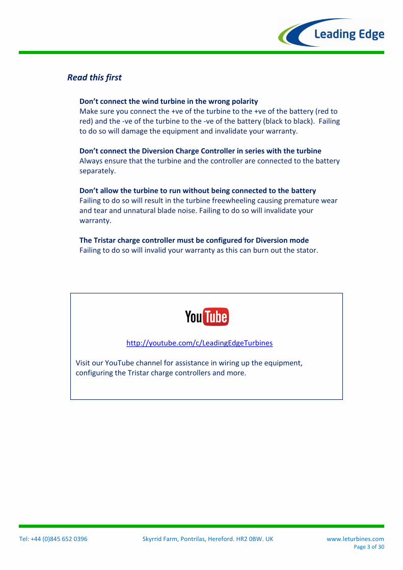
Read this first
Don’t connect the wind turbine in the wrong polarity Make sure you connect the +ve of the turbine to the +ve of the battery (red to red) and the -ve of the turbine to the -ve of the battery (black to black). Failing to do so will damage the equipment and invalidate your warranty.
Don’t connect the Diversion Charge Controller in series with the turbine Always ensure that the turbine and the controller are connected to the battery separately.
Don’t allow the turbine to run without being connected to the battery Failing to do so will result in the turbine freewheeling causing premature wear and tear and unnatural blade noise. Failing to do so will invalidate your warranty. The Tristar charge controller must be configured for Diversion mode Failing to do so will invalid your warranty as this can burn out the stator.
http://youtube.com/c/LeadingEdgeTurbines
Visit our YouTube channel for assistance in wiring up the equipment, configuring the Tristar charge controllers and more.

Tel: +44 (0)845 652 0396 Skyrrid Farm, Pontrilas, Hereford. HR2 0BW. UK www.leturbines.com Page 4 of 30
Introduction Please read this manual thoroughly before attempting to assemble, install or operate the LE-3000 small wind turbine. This will assure optimum performance and safety. The LE-3000 turbine should only be installed by a Leading Edge Turbines Ltd trained installer. Leading Edge Turbines has spent many years developing the technology behind the turbine, mast and control systems. The LE-3000 turbine features an array of innovations and construction techniques as well as heavy-duty engineering to ensure optimum efficiency and a long operating life. The LE-3000 has been designed to be simple, economic, durable and yield excellent performance. The LE-3000 turbine & system components features:
Innovative design axial flux alternator using neodymium iron boron magnets.
A laser-cut galvanised steel chassis using 'Yaw-wing' design to ensure responsive yawing
Maintenance-free, low friction bearing arrangements.
Long-life, aerospace grade yaw pivot slip-rings.
Easy tower-top installation.
Simple design for low cost and durability.
Stainless steel fixings and anodised aluminium components.
Low mass to help reduce exerted forces and ensure easy installation.
Flexible Flight Control Computer to closely control turbine function.
High Voltage Transformer function (battery charger versions), to minimise cable losses and cost
Aesthetically pleasing free standing tower operated by hydraulic lift for ultimate lift and control
LE-3000 is has been designed to for land-based environments. Thanks to its unique design, the LE-3000 is not susceptible to corrosion in normal or salt rich atmosphere operating conditions. Applications include:
Domestic or light commercial grid-connected power generation
General off-grid high power applications
Remote off-grid Homes & dwellings
Complementary installation with photovoltaic modules for home power
Farm utilities
Wind-electric water pumping
Cathodic protection
Monitoring sites
Radio and Telecommunication
The Developing World This Assembly manual assumes that the tower has already been installed and assembled as per the relevant technical drawings and instructions for the tower itself. The first half of the manual describes the mechanical assembly procedures, whilst the following section gives guidelines on the electrical installation of the turbine systems. Turbine operation is described in part 3 of the manual.

Tel: +44 (0)845 652 0396 Skyrrid Farm, Pontrilas, Hereford. HR2 0BW. UK www.leturbines.com Page 5 of 30
Safety Precautions Safety must always be your primary concern during the assembly, installation and operation of your LE-3000 turbine, tower and control system. Always be aware of the risks involved with mechanical and electrical installation work. If in doubt about any issue regarding your turbine or associated components, please seek further assistance before proceeding. Installation of the LE-3000 turbine should only be undertaken by suitably competent and qualified personnel. Mechanical Safety Hazards
The main rotor is the most obvious and serious mechanical safety risk. When the turbine is operating at its rated performance, the blades will be very difficult to see due to the speed of rotation. Never approach the turbine whilst it is operating. Always shut down the turbine by activating the stop switch. Ensure that the turbine is installed in a suitable position where nobody can approach or interfere with the path of the rotor blades.
Working with tools of any kind can be dangerous. Your LE-3000 turbine and associated components require some heavy duty mechanical assembly and handling tools. If you are in any doubt about how to use these tools correctly, please seek advice from a suitably experienced person.
Your LE-3000 turbine will inevitably be installed upon a tower. This may mean working at height. Always ensure that all personnel in the immediate vicinity are aware of any lifting / hoisting operations that will be occurring. Check there are no loose components or tools likely to fall and cause injury during the lifting operation. Where possible, all assembly work should be completed at ground level.
Ensure that the batteries are disconnected during the installation procedure.
Ensure that the LE-3000 turbine is electrically connected to the ‘Run / Stop Switch’ and this is set in the stop position. This will prevent the turbine from ‘spinning up’ during the installation.
Install your turbine during a calm day.
When performing routine inspection or maintenance, always stop the turbine by activating the stop switch.
Electrical Safety Hazards
The LE-3000 generates 3-Phase AC voltage from the turbine head and rectified DC voltage from the Flight Control Computer enclosure. Even at low voltages there are inherent risks. Caution should always be used when connecting LE-3000 systems to the general electrical system.
Ensure that you have followed the cable-sizing chart to ensure that the correct size of transmission cable has been selected. If a cable of insufficient cross-sectional area is used, heat may build up in the cables causing a potential fire hazard. A properly sized fuse or circuit breaker should be used in the cables connected to the battery. This will stop the risk of short circuit currents. Using cables of insufficient cross-sectional area may also reduce the power transmission efficiency of the turbine.
Battery systems can deliver a serious amount of current. A short circuit in the battery circuit can lead to hundreds of amps flowing through the battery cables. This will cause a heat build-up and ultimately an electrical fire. Batteries can explode when shorted. Always use insulated electrical tools when working on the battery’s electrical connections.
Batteries are very heavy. Do not attempt to move batteries by yourself. Always use manual handling tools and an assistant.
Always keep lead-acid batteries the correct way up. Do not allow the acidic electrolyte to spill or come into contact with your skin or face. Always follow the manufacturer’s safety instructions when handling lead-acid batteries.
Never run the LE-3000 'off-load' with the output cables not connected to anything
Please use common sense when installing and operating your turbine!
Tel: +44 (0)845 652 0396 Skyrrid Farm, Pontrilas, Hereford. HR2 0BW. UK www.leturbines.com Page 6 of 30
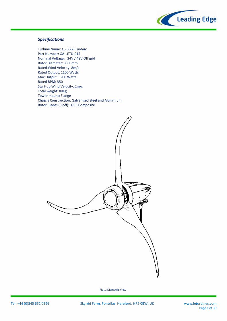
Specifications Turbine Name: LE-3000 Turbine Part Number: GA-LETU-015 Nominal Voltage: 24V / 48V Off grid Rotor Diameter: 3305mm Rated Wind Velocity: 8m/s Rated Output: 1100 Watts Max Output: 3200 Watts Rated RPM: 350 Start-up Wind Velocity: 2m/s Total weight: 80Kg Tower mount: Flange Chassis Construction: Galvanised steel and Aluminium Rotor Blades (3-off): GRP Composite
Fig-1: Diametric View
Tel: +44 (0)845 652 0396 Skyrrid Farm, Pontrilas, Hereford. HR2 0BW. UK www.leturbines.com Page 7 of 30
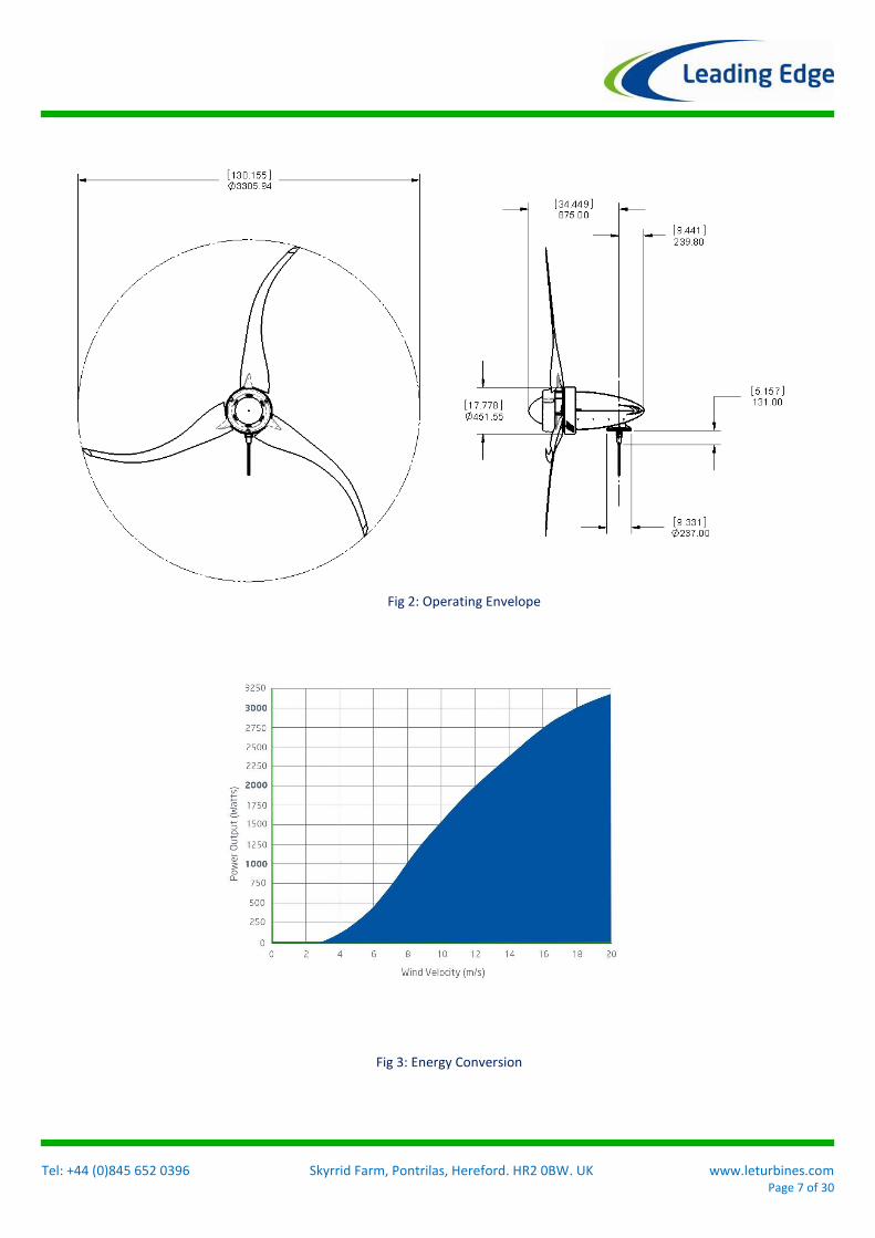
Fig 2: Operating Envelope
Fig 3: Energy Conversion

Tel: +44 (0)845 652 0396 Skyrrid Farm, Pontrilas, Hereford. HR2 0BW. UK www.leturbines.com Page 8 of 30
Package Contents Your LE-3000 Turbine package will arrive containing the components shown below. If any of the components are missing or damaged, please contact your dealer immediately. The tower is a separate item and is packed and shipped as such.
LE-3000 Chassis: Qty 1 ‘Whispower’ Rotor Blade: Qty 3
‘Whispower’ Hub Plates: Qty 2
User Manual: Qty 1
8 x M12 x65lg Hex heads 40 x M12 Plain Washers 20x M12 Nylock Nuts 12 x M12 x 120lg Hex heads 6x M10 x 40lg Hex Head 6x M10 Spring Washers 6x M10 Plain Washers 3x M8 x 20lg Hex Head
Fixings Bag: Qty 1
Nose Cone: Qty 1
Flight Control Computer Control Box: Qty 1
Tristar Charge controller: Qty 1 or Qty 2 (depending
on voltage)
Dump load Resistor: Qty 3
Run / Stop Switch: Qty 1

Tel: +44 (0)845 652 0396 Skyrrid Farm, Pontrilas, Hereford. HR2 0BW. UK www.leturbines.com Page 9 of 30
Minimum Tools Requirements The LE-3000 turbine is a substantial piece of equipment and should only be installed by suitably trained and equipped technicians. Attempting to install the LE-3000 without proper tools, knowledge or experience, may result in extremely dangerous installation procedures and / or turbine operation. If in doubt about any element of the turbine installation, please refer to Leading Edge Turbines. Installation technicians will need to be equipped with a myriad of mechanical and electrical installation tools usually associated with large electro-mechanical equipment. Specifically, you will require the following tools to assemble your LE-3000 Turbine:
19mm A/F spanner & 19mm ratchet (one of each required)
13mm A/F spanner & 13mm ratchet (one of each required)
150mm Socket Extension bar
Torque Wrench (capable of 20Nm)
Torque Wrench (capable of 70Nm)
A Set of Metric Standard Hexagon Keys
Electrical screw drivers
Digital multi-meter capable of measuring DC & AC Volts
Tape measure or steel rule
Thread Locking compound (Loctite 243 or similar)
Tel: +44 (0)845 652 0396 Skyrrid Farm, Pontrilas, Hereford. HR2 0BW. UK www.leturbines.com Page 10 of 30
Mechanical Assembly Procedure
1) Unpacking- Inspect the contents of the box and ensure that all items are present and free from damage. If any of the components are missing or damaged, please contact your dealer immediately.
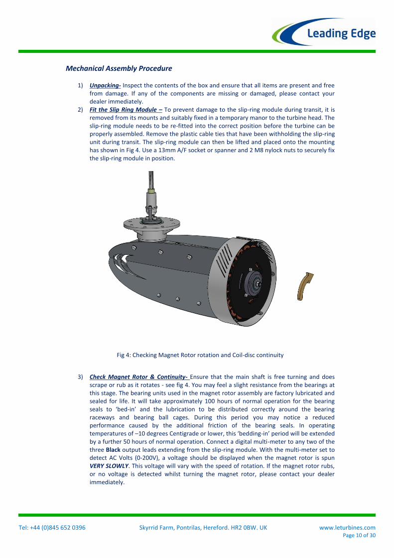
2) Fit the Slip Ring Module – To prevent damage to the slip-ring module during transit, it is removed from its mounts and suitably fixed in a temporary manor to the turbine head. The slip-ring module needs to be re-fitted into the correct position before the turbine can be properly assembled. Remove the plastic cable ties that have been withholding the slip-ring unit during transit. The slip-ring module can then be lifted and placed onto the mounting has shown in Fig 4. Use a 13mm A/F socket or spanner and 2 M8 nylock nuts to securely fix the slip-ring module in position.
3) Check Magnet Rotor & Continuity- Ensure that the main shaft is free turning and does scrape or rub as it rotates - see fig 4. You may feel a slight resistance from the bearings at this stage. The bearing units used in the magnet rotor assembly are factory lubricated and sealed for life. It will take approximately 100 hours of normal operation for the bearing seals to ‘bed-in’ and the lubrication to be distributed correctly around the bearing raceways and bearing ball cages. During this period you may notice a reduced performance caused by the additional friction of the bearing seals. In operating temperatures of –10 degrees Centigrade or lower, this ‘bedding-in’ period will be extended by a further 50 hours of normal operation. Connect a digital multi-meter to any two of the three Black output leads extending from the slip-ring module. With the multi-meter set to detect AC Volts (0-200V), a voltage should be displayed when the magnet rotor is spun VERY SLOWLY. This voltage will vary with the speed of rotation. If the magnet rotor rubs, or no voltage is detected whilst turning the magnet rotor, please contact your dealer immediately.
Fig 4: Checking Magnet Rotor rotation and Coil-disc continuity
Tel: +44 (0)845 652 0396 Skyrrid Farm, Pontrilas, Hereford. HR2 0BW. UK www.leturbines.com Page 11 of 30
Warning: The magnet rotor within your LE-3000 turbine is constructed using neodymium iron boron rare earth magnets which are semi-exposed until the turbine is fully assembled. These are extremely powerful magnets and can cause injury if not handled with respect. Take care when working with tools made of ferrous materials (such as spanners and screwdrivers) close to LE-3000 alternator. The magnetic forces between ferrous materials and the magnet rotor within the alternator, maybe very strong. This may cause a sudden snapping action that can pinch or trap your fingers or skin. Warning: Very high open circuit voltages can be generated from the turbine alternator even when spun by hand. Do not touch any of the 3 black cables whilst the operation described is being completed. Ensure that a suitable terminal block or set of crocodile clips is used to connect the multi-meter to the turbine output cables. Note: 2 white cables can be found emerging from the slip-ring module alongside 3 black cables. The 3 black cables are the power transmission cables and the 2 white cables are used for control signal transmission and are redundant on most versions of the LE-3000 turbine.
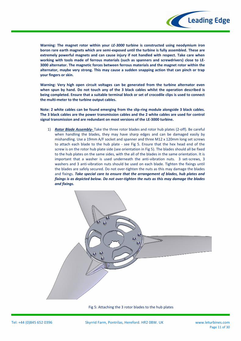
1) Rotor Blade Assembly- Take the three rotor blades and rotor hub plates (2-off). Be careful when handling the blades, they may have sharp edges and can be damaged easily by mishandling. Use a 19mm A/F socket and spanner and three M12 x 120mm long set screws to attach each blade to the hub plate - see Fig 5. Ensure that the hex head end of the screw is on the rotor hub plate side (see orientation in Fig 5). The blades should all be fixed to the hub plates on the same sides, with the all of the blades in the same orientation. It is important that a washer is used underneath the anti-vibration nuts. 3 set-screws, 3 washers and 3 anti-vibration nuts should be used on each blade. Tighten the fixings until the blades are safely secured. Do not over-tighten the nuts as this may damage the blades and fixings. Take special care to ensure that the arrangement of blades, hub plates and fixings is as depicted below. Do not over-tighten the nuts as this may damage the blades and fixings.
Fig 5: Attaching the 3 rotor blades to the hub plates
Tel: +44 (0)845 652 0396 Skyrrid Farm, Pontrilas, Hereford. HR2 0BW. UK www.leturbines.com Page 12 of 30
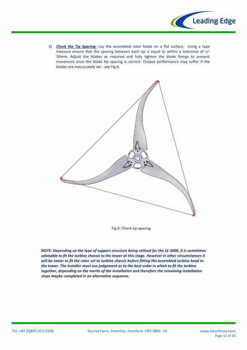
2) Check the Tip Spacing- Lay the assembled rotor blade on a flat surface. Using a tape measure ensure that the spacing between each tip is equal to within a tolerance of +/-10mm. Adjust the blades as required and fully tighten the blade fixings to prevent movement once the blade tip spacing is correct. Output performance may suffer if the blades are inaccurately set - see Fig 6.
NOTE: Depending on the type of support structure being utilised for the LE-3000, it is sometimes advisable to fit the turbine chassis to the tower at this stage. However in other circumstances it will be easier to fit the rotor set to turbine chassis before fitting the assembled turbine head to the tower. The installer must use judgement as to the best order in which to fit the turbine together, depending on the merits of the installation and therefore the remaining installation steps maybe completed in an alternative sequence.
Fig 6: Check tip spacing
Tel: +44 (0)845 652 0396 Skyrrid Farm, Pontrilas, Hereford. HR2 0BW. UK www.leturbines.com Page 13 of 30
3) Install the ‘Down-tower Cable’- Before the tower is ready to receive its turbine, the next
stage is to run the cables from the top of the tower to the base, where a junction box will be located. This junction box will take the down-tower cable to the previously installed transmission cable.
The down-tower cable should be 3-Core, 2.5mm2, ‘YY’ flexible cable which should have 2 -3 metres of surplus length compared to the height of the tower.
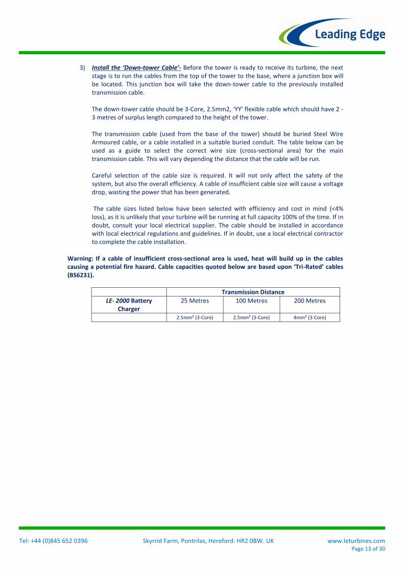
The transmission cable (used from the base of the tower) should be buried Steel Wire Armoured cable, or a cable installed in a suitable buried conduit. The table below can be used as a guide to select the correct wire size (cross-sectional area) for the main transmission cable. This will vary depending the distance that the cable will be run. Careful selection of the cable size is required. It will not only affect the safety of the system, but also the overall efficiency. A cable of insufficient cable size will cause a voltage drop, wasting the power that has been generated. The cable sizes listed below have been selected with efficiency and cost in mind (<4% loss), as it is unlikely that your turbine will be running at full capacity 100% of the time. If in doubt, consult your local electrical supplier. The cable should be installed in accordance with local electrical regulations and guidelines. If in doubt, use a local electrical contractor to complete the cable installation.
Warning: If a cable of insufficient cross-sectional area is used, heat will build up in the cables causing a potential fire hazard. Cable capacities quoted below are based upon ‘Tri-Rated’ cables (BS6231).
Transmission Distance
LE- 2000 Battery Charger
25 Metres
100 Metres
200 Metres
2.5mm² (3-Core) 2.5mm² (3-Core) 4mm² (3-Core)
Tel: +44 (0)845 652 0396 Skyrrid Farm, Pontrilas, Hereford. HR2 0BW. UK www.leturbines.com Page 14 of 30
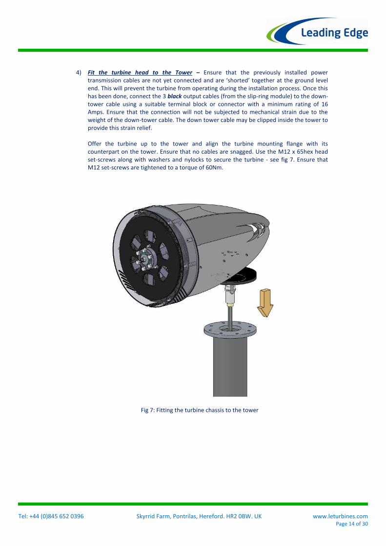
4) Fit the turbine head to the Tower – Ensure that the previously installed power transmission cables are not yet connected and are ‘shorted’ together at the ground level end. This will prevent the turbine from operating during the installation process. Once this has been done, connect the 3 black output cables (from the slip-ring module) to the down-tower cable using a suitable terminal block or connector with a minimum rating of 16 Amps. Ensure that the connection will not be subjected to mechanical strain due to the weight of the down-tower cable. The down tower cable may be clipped inside the tower to provide this strain relief. Offer the turbine up to the tower and align the turbine mounting flange with its counterpart on the tower. Ensure that no cables are snagged. Use the M12 x 65hex head set-screws along with washers and nylocks to secure the turbine - see fig 7. Ensure that M12 set-screws are tightened to a torque of 60Nm.
Fig 7: Fitting the turbine chassis to the tower
Tel: +44 (0)845 652 0396 Skyrrid Farm, Pontrilas, Hereford. HR2 0BW. UK www.leturbines.com Page 15 of 30
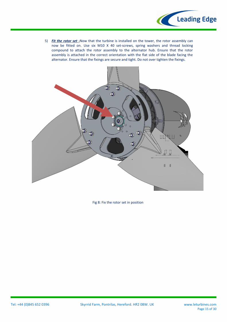
5) Fit the rotor set -Now that the turbine is installed on the tower, the rotor assembly can now be fitted on. Use six M10 X 40 set-screws, spring washers and thread locking compound to attach the rotor assembly to the alternator hub. Ensure that the rotor assembly is attached in the correct orientation with the flat side of the blade facing the alternator. Ensure that the fixings are secure and tight. Do not over tighten the fixings.
Fig 8: Fix the rotor set in position
Tel: +44 (0)845 652 0396 Skyrrid Farm, Pontrilas, Hereford. HR2 0BW. UK www.leturbines.com Page 16 of 30
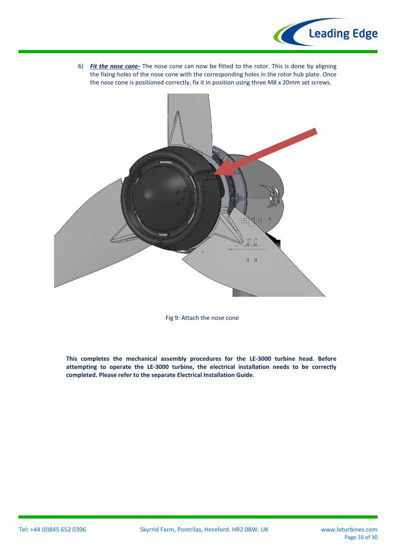
6) Fit the nose cone- The nose cone can now be fitted to the rotor. This is done by aligning
the fixing holes of the nose cone with the corresponding holes in the rotor hub plate. Once the nose cone is positioned correctly, fix it in position using three M8 x 20mm set screws.
This completes the mechanical assembly procedures for the LE-3000 turbine head. Before attempting to operate the LE-3000 turbine, the electrical installation needs to be correctly completed. Please refer to the separate Electrical Installation Guide.
Fig 9: Attach the nose cone

Tel: +44 (0)845 652 0396 Skyrrid Farm, Pontrilas, Hereford. HR2 0BW. UK www.leturbines.com Page 17 of 30
Electrical Installation for Battery Charging (Off-grid)
LE-3000 Turbines

Tel: +44 (0)845 652 0396 Skyrrid Farm, Pontrilas, Hereford. HR2 0BW. UK www.leturbines.com Page 18 of 30
Introduction The core of the electrical installation for the LE-3000 turbine is focused around the Flight Control Computer (abbreviated as FCC). Battery charging versions of the LE-3000 also use a High Voltage transformer system to reduce the high voltage output from the turbine head down to a suitable voltage for the battery bank (either 24V or 48V nominally). The FCC provides a number of control functions that are important to allow the LE-3000 turbine to function effectively and reliably through various wind conditions. The FCC has further features that provide charge control for off-grid systems. FCC Description: The Leading Edge Flight Control Computer (FCC) is a flexible control system used to maximise the function and protection of Leading Edge turbines both in battery charging systems. The FCC includes a central logic controller, various turbine sensors, braking resistors and other auxiliary inputs and outputs that allow the unit to operate the turbine in the best manner for the prevailing weather conditions and system status. FCC Features include: • High wind event turbine shut down. The FCC continuously monitors the output of the turbine and automatically shuts the turbine down if the operating envelope of the turbine is exceeded. This prevents turbine damage and wear during high wind events, whilst helping to maximise the turbine output. Typically, the FCC will shut off the turbine if parameters have been exceeded for more than a specified period of time. The FCC will then periodically measure the operating conditions for the turbine and allow the turbine to run once wind conditions are within the operating limits of the turbine. • Special functions. Additional inputs and control functions can be integrated into the FCC to make a flexible control system. Turbine noise sensors, vibration sensors or time of day are just some of the things that can be used to control the turbine accordingly.

Tel: +44 (0)845 652 0396 Skyrrid Farm, Pontrilas, Hereford. HR2 0BW. UK www.leturbines.com Page 19 of 30
Minimum Tools Requirements for Electrical Installation The LE-3000 electrical system and FCC is a sophisticated piece of electrical equipment and should only be installed by suitably trained and equipped technicians. Attempting to install the LE-3000 electrical system without proper tools, knowledge or experience, may result in extremely dangerous installation procedures and / or turbine operation. If in doubt about any element of the turbine installation, please refer to Leading Edge Turbines. Installation technicians will need to be equipped with a myriad of mechanical and electrical installation tools usually associated with large electro-mechanical equipment. Specifically, you will require the following tools to assemble your LE-3000 Turbine:
Electric drill with a set of masonry bits
Wall plugs (‘rawl’ plugs and suitable screws)
A Set of Metric Standard Hexagon Keys
Electrical screw drivers
Digital multi-meter capable of measuring DC & AC Volts
Tape measure or steel rule
Note: The Tristar charge controllers must be correctly installed and configured to operate as ‘Diversion charge controllers’. Refer to the manual included with the Tristar controller for detailed instruction regarding installation and configuration as Diversion Charge Controllers. Dip Switch settings for diversion charge controller configuration can be found in Appendix 2 of the Tristar manual. Alternatively watch the video on how to configure the Tristar charge controller at http://youtube.com/c/leadingedgeturbines

Tel: +44 (0)845 652 0396 Skyrrid Farm, Pontrilas, Hereford. HR2 0BW. UK www.leturbines.com Page 20 of 30
Mechanical Fixing of the Flight Control Computer (FCC)
1) Unpacking- The FCC is shipped in an individual cardboard carton fixed to the main LE-3000 shipping pallet. This carton simply contains the IP rated electrical enclosure, and inside this is the main control panel of the FCC. For off-grid battery charging turbines, a second electrical panel is fitted in the FCC enclosure (underneath the main electrical panel). This second panel holds the transformer system. A second package contains the Tristar controller and dump load resistor. Inspect the contents of the box and ensure that all items are present and free from damage. If any of the components are missing or damaged, please contact your dealer immediately.
Fig 1: FCC Packing and inside layout

Tel: +44 (0)845 652 0396 Skyrrid Farm, Pontrilas, Hereford. HR2 0BW. UK www.leturbines.com Page 21 of 30
2) Mount the FCC, Tristar & Dump load– The FCC, Tristar charge controller and dump load all need to be mounted to a suitable wall or suitable surface in very close proximity to the battery bank. It is not recommended that the distance from the control boxes to the battery bank exceeds 3m as this may result in large voltage drops and losses in the DC cables to the battery bank.
The wall or vertical surface needs to be of substantial strength due to the weight of the transformers which make up the FCC. It is not recommended that the equipment is mounted on plasterboard or stud wall surfaces. The Tristar charge controller and dump loads may get hot during operation. It is essential that the dump loads are fitted onto a heat resistant surface and are not fully enclosed to allow convection of air which has been heated by the dump loads. Use suitable masonry drill, wall plugs and screws where appropriate. It is often good practice to fit a wooden backing board to the area where the control equipment will be mounted. Allow a gap of around 75 – 100mm around each of the control boxes. This will allow easy access for drilling / fitting cables glands and feeding cables etc. Trunking and / or conduit should be used to run the cables to and from the control boxes. Give consideration to the layout and routing of the trunking during the mounting of the control boxes.
Note: When mounting the FCC enclosure to the wall, it will most likely be necessary to remove the FCC panel from inside the cabinet. Both the main FCC panel and the transformer panel will need to be removed. The panel fixings can be found in each corner of the panel. The main FCC panel and the transformer panel are connected together electrically, so care must be taken when removing both electrical panels.

Tel: +44 (0)845 652 0396 Skyrrid Farm, Pontrilas, Hereford. HR2 0BW. UK www.leturbines.com Page 22 of 30
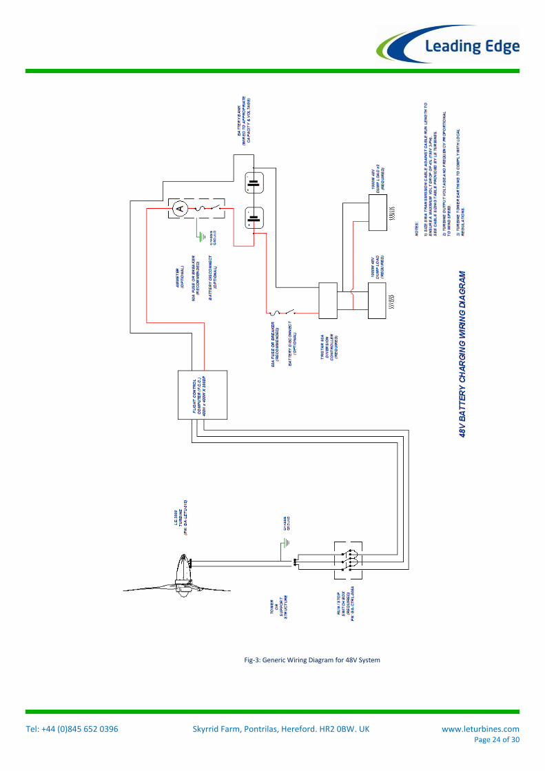
3) Make the electrical connections –The electrical connections can now begin to be made to and from the FCC, Tristar / dump load and the battery bank. Use the generic wiring diagram and terminal identification photo graphs in Figs 3-5 to complete the wiring.
Holes in the control boxes may have to be drilled to suit the direction and position of cable entry into the control box. Always use a suitably sized cable gland or rubber grommet to support the cable as it enters the control box. Failure to do this may lead to mechanical strain on the cables and damage to the cable insulation A guide to cable sizes and lengths is described on the generic interconnect diagram shown in Fig 2 (24V) and Fig 3 (48V).
Warning: Very high voltages are present during inside the FCC and transformer panel. Do not allow the turbine to run, or power up the FCC until all of the electrical connections have been made. Do not make contact with the insides of the FCC or transformer box whilst the turbine is running or the FCC is powered up. Warning: Ensure that the turbine tower is not erected during the installation and connection of the electrical equipment. If the turbine is allow to spin freely at any point, dangerous high open circuit voltages will be present in the 3 phase output cables from the LE-3000 turbine head.

Tel: +44 (0)845 652 0396 Skyrrid Farm, Pontrilas, Hereford. HR2 0BW. UK www.leturbines.com Page 23 of 30
Fig-2: Generic Wiring Diagram for 24V System
Tel: +44 (0)845 652 0396 Skyrrid Farm, Pontrilas, Hereford. HR2 0BW. UK www.leturbines.com Page 24 of 30
Fig-3: Generic Wiring Diagram for 48V System
Tel: +44 (0)845 652 0396 Skyrrid Farm, Pontrilas, Hereford. HR2 0BW. UK www.leturbines.com Page 25 of 30
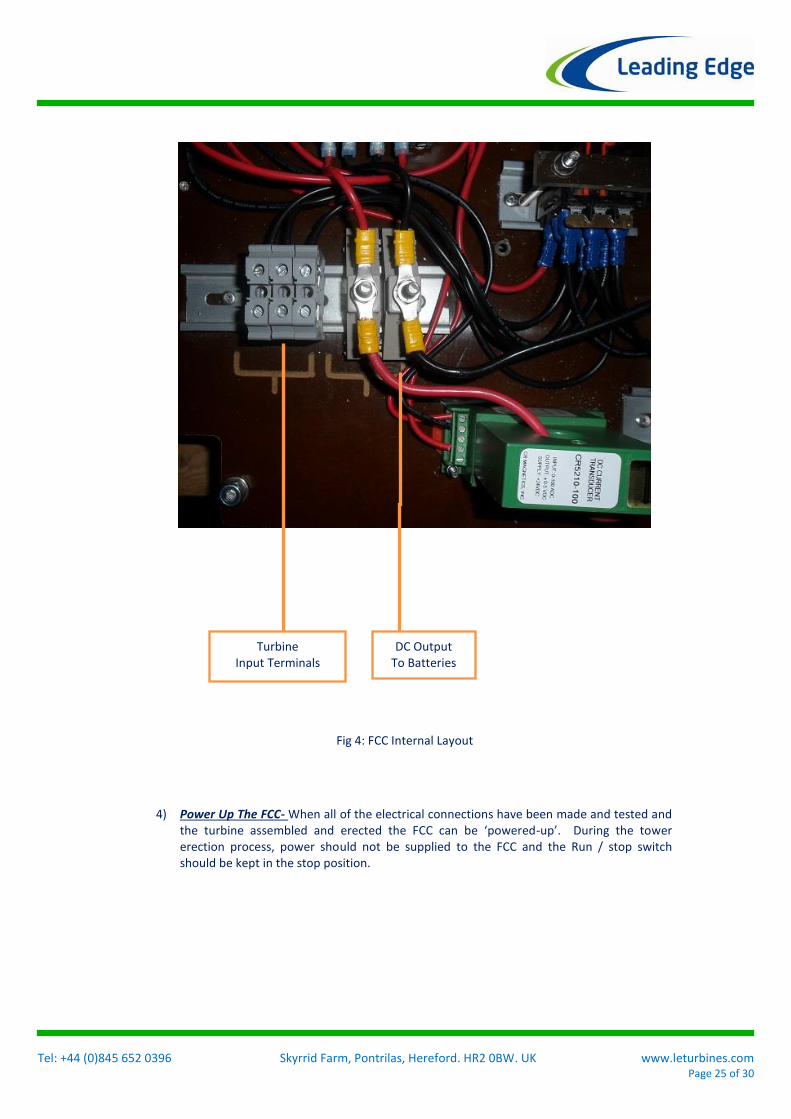
4) Power Up The FCC- When all of the electrical connections have been made and tested and the turbine assembled and erected the FCC can be ‘powered-up’. During the tower erection process, power should not be supplied to the FCC and the Run / stop switch should be kept in the stop position.
Turbine Input Terminals
DC Output To Batteries
Fig 4: FCC Internal Layout

Tel: +44 (0)845 652 0396 Skyrrid Farm, Pontrilas, Hereford. HR2 0BW. UK www.leturbines.com Page 26 of 30
Warranty Your LE-3000 Turbine from Leading Edge Turbines (LET) carries a two-year warranty, as supported by a retailer’s receipt. The warranty starts from the date of installation or ninety (90) days after shipment from the LET factory, whichever comes first. LET will supply ‘non-wearing’ parts at no cost. For minor component failures, replacements may be sent directly to the customer / dealer for replacement by them. For more serious defects we may suggest a ‘return-to-base’ arrangement for replacement or repair. In these cases, the purchaser will be responsible for taking the turbine off the tower/mast and paying the return carriage costs. Where a turbine is to be replaced, it must be returned to LET before the replacement unit is despatched. Should the product prove to be irreparable, LET reserves the right to substitute an equivalent product, if available. This warranty does not extend to servicing a faulty turbine on location. In all cases LET will take reasonable action to ensure customer satisfaction. You should always receive a warm, courteous service in or out of your warranty period. Your turbine must be installed and operated in accordance with the guide. Failure to do so will result in this warranty becoming null and void. Any unauthorised modifications to the turbine design will void the warranty and may compromise the safety of the machine. What is not covered by your warranty?
Damage caused by unsatisfactory installation of the turbine, tower and/or control equipment.
Damage caused by the neglect of periodic maintenance in the manner recommended in the installation manual.
Damage caused by repair or maintenance performed using methods not specified by LET or by non-authorised dealers of LET products.
Damaged caused by the use of non-genuine parts, or from the use of liquid agents or lubricants in or on the turbine, tower or control equipment.
Damage caused by operating the turbine in conditions outside of those specified in the Owner’s Guide – including, but not limited to, allowing the turbine to run while disconnected from the batteries or not configuring the Tristar charge controller for diversion mode.
Damage caused by modifications to the turbine, tower or control equipment not approved by LET.
Damage caused to the turbine, tower and control equipment by improper storage or transport.
Damage caused by lightning strikes, flooding, fire, etc.
Damage due to extremely high winds and storm conditions (27m/s+, 60 mph+).
Damage caused by flying debris.
Damage to batteries due to excessive deep discharge, short-circuiting, excessively high load, over charging, loss of electrolyte, or any condition outside of the manufacturer's specification for battery use.
Damage occurring as a result of not operating the turbine at a safe distance from individuals or property.
Damage caused by unsatisfactory tower / support structure design.

Tel: +44 (0)845 652 0396 Skyrrid Farm, Pontrilas, Hereford. HR2 0BW. UK www.leturbines.com Page 27 of 30
Damage caused by incorrect connection to external electrical equipment, or failure to observe current regulations concerning connection to external electrical networks, equipment or any other devices.
If you should experience a problem with your turbine, your first ‘port-of-call’ should be the reseller or installer from whom you purchased the product. They should be able to resolve the problem quickly and efficiently. If you are unable to contact the original reseller, then please contact us directly. Please quote the serial number of your turbine when dealing with warranty issues. The serial number can be found on the nameplate positioned on the underside of the chassis.
Disclaimer
All specifications are subject to change without prior notice.
The information given in this user manual is believed to be accurate and reliable. Leading Edge Turbines assumes no responsibility for omissions or inaccuracies.
The user of this information and product assumes full responsibility and risk.
The LE-3000 Turbine is a source of electrical power. It must be installed in accordance with local building and electrical regulations. Consult your local planning (zoning) office for details.
The LE-3000 Turbine has moving parts that may cause injury due to poor installation and unsafe operation. Leading Edge Turbines assumes no responsibility for problems caused by unsafe or unsatisfactory installation or operation.
Designed & Manufactured in the UK by: Leading Edge Turbines Ltd
Skyrrid Farm, Pontrilas, Hereford. HR2 0BW
Tel: +44 (0)1981 241668 www.leturbines.com
Compliant with EN BS 61400-2: Safety of Small Wind
Turbines
Tel: +44 (0)845 652 0396 Skyrrid Farm, Pontrilas, Hereford. HR2 0BW. UK www.leturbines.com Page 28 of 30
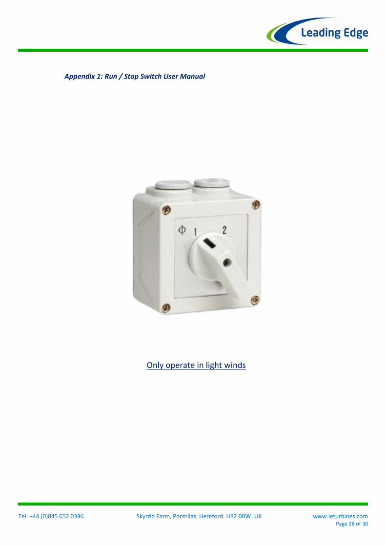
Appendix 1: Run / Stop Switch User Manual
Only operate in light winds
Tel: +44 (0)845 652 0396 Skyrrid Farm, Pontrilas, Hereford. HR2 0BW. UK www.leturbines.com Page 29 of 30
Introduction Please read this manual thoroughly before attempting to assemble, install or operate your Universal Run / Stop Switch. This will assure optimum performance and safety. The Universal Run / Stop Switch is a solution designed to allow the user to brake dynamically an LE-3000 at will. This is achieved by disconnecting the power output of the turbine from the relevant load and diverting it to a short circuit which then applies the dynamic braking effect on the permanent magnet alternator of the turbine. This will bring the turbine to a near stop for maintenance only. The Universal Run / Stop Switch can be used with turbines of different manufacture as long as the relevant turbine has the following characteristics: 3-Phase Wild AC not exceeding 500 V & 16 A Wild DC not exceeding 150 V & 10 A Mechanically and electrically capable of dynamic braking Operation & Specification The Universal Run / Stop Switch should be operated during low speeds as repeated use at high speeds may cause damage if the turbine head (it was not designed to withstand repeated dynamic braking operations). The switch has 2 positions: Position 1: Turbine 'Stop' position. The turbine is dynamically braked and may be seen to rotate very slowly. Position 2: Turbine 'Run' position. The turbine output is allowed to flow straight through the switch to the relevant output. Safety Precautions Safety must always be your primary concern during the assembly, installation and operation of your turbine and other associated equipment. Always be aware of the risks involved with mechanical and electrical installation work. If in doubt about any issue regarding your turbine system, please seek further assistance before proceeding. Mechanical Safety Hazards: Whilst installing the Universal Run / Stop Switch, ensure that the turbine is suitable restrained and not allowed to operate during the installation. Electrical Safety Hazards: The LE-3000 generates rectified DC voltage and the Universal Run / Stop Switch also operates at these voltages. Even at these low voltages there are inherent risks. Caution should always be used when connecting LE-3000 or other equipment to the electrical system. The LE-3000 can generate high voltage AC, and the Universal Run / Stop Switch also operates at these voltages. Such voltages bring with them significant risks.
Tel: +44 (0)845 652 0396 Skyrrid Farm, Pontrilas, Hereford. HR2 0BW. UK www.leturbines.com Page 30 of 30
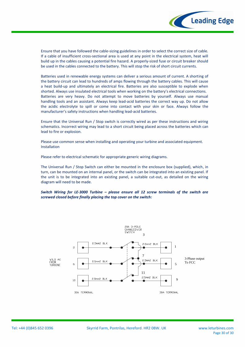
Ensure that you have followed the cable-sizing guidelines in order to select the correct size of cable. If a cable of insufficient cross-sectional area is used at any point in the electrical system, heat will build up in the cables causing a potential fire hazard. A properly-sized fuse or circuit breaker should be used in the cables connected to the battery. This will stop the risk of short circuit currents. Batteries used in renewable energy systems can deliver a serious amount of current. A shorting of the battery circuit can lead to hundreds of amps flowing through the battery cables. This will cause a heat build-up and ultimately an electrical fire. Batteries are also susceptible to explode when shorted. Always use insulated electrical tools when working on the battery’s electrical connections. Batteries are very heavy. Do not attempt to move batteries by yourself. Always use manual handling tools and an assistant. Always keep lead-acid batteries the correct way up. Do not allow the acidic electrolyte to spill or come into contact with your skin or face. Always follow the manufacturer’s safety instructions when handling lead-acid batteries. Ensure that the Universal Run / Stop switch is correctly wired as per these instructions and wiring schematics. Incorrect wiring may lead to a short circuit being placed across the batteries which can lead to fire or explosion. Please use common sense when installing and operating your turbine and associated equipment. Installation Please refer to electrical schematic for appropriate generic wiring diagrams. The Universal Run / Stop Switch can either be mounted in the enclosure box (supplied), which, in turn, can be mounted on an internal panel, or the switch can be integrated into an existing panel. If the unit is to be integrated into an existing panel, a suitable cut-out, as detailed on the wiring diagram will need to be made. Switch Wiring for LE-3000 Turbine – please ensure all 12 screw terminals of the switch are screwed closed before finally placing the top cover on the switch:
3
11
7
1
5
9
3-Phase output
To FCC