Embed Size (px)
Citation preview

Lecture 5: IEEE 802.11Lecture 5: IEEE 802.11
Hung-Yu WeiNational Taiwan University
IEEE 802.11IEEE 802.11

3
OOutline: 802.11utline: 802.11• 802.11 network terminologies• PHY• MAC• Management functions
– Registration– Handoff– Power management– Security

4
802.11 Network Terminologies802.11 Network Terminologies• BSS• BSA• ESS• IBSS

5
BSS BSS • basic service set (BSS): A set of stations
controlled by a single coordination function– [concept] A cell with 1 AP and some MSs
BSA (basic service area): cell

6
IBSSIBSS• Independent basic service set (IBSS): stand-alone BSS– [concept] Ad hoc network

7
ESSESS• Extended service set (ESS): A set of one or
more interconnected basic service sets (BSSs) and integrated local area networks (LANs)– [concept] Cellular system with multiple cells and
multiple BSs• Identifier
– ESSID: network name– BSSID: MAC address of AP– Several BSSID with 1 ESSID

8
ESSESS• Two topologies
– No overlap– With overlap
9
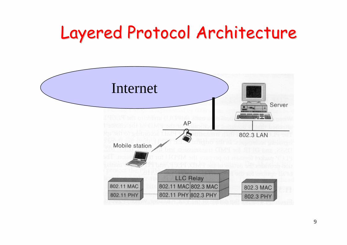
Layered Protocol ArchitectureLayered Protocol Architecture
Internet
10
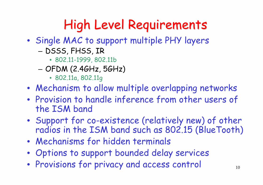
High Level RequirementsHigh Level Requirements• Single MAC to support multiple PHY layers
– DSSS, FHSS, IR• 802.11-1999, 802.11b
– OFDM (2.4GHz, 5GHz)• 802.11a, 802.11g
• Mechanism to allow multiple overlapping networks• Provision to handle inference from other users of
the ISM band• Support for co-existence (relatively new) of other
radios in the ISM band such as 802.15 (BlueTooth)• Mechanisms for hidden terminals• Options to support bounded delay services• Provisions for privacy and access control

IEEE 802.11 Protocol StackIEEE 802.11 Protocol Stack

12
Layered ProtocolLayered Protocol
MACheader
LLCheader
IPheader
TCPheader
Application Data Application Layer
TCP Layer
IP Layer
LLC Layer
MAC LayerMACtrailer
TCP segment
IP datagram
LLC protocol data unit
MAC frame

13
802.11 Protocol Stack Overview802.11 Protocol Stack Overview
All protocols in 802 family use LLC
802.11
14
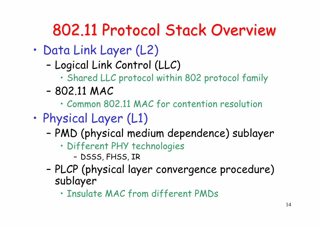
802.11 Protocol Stack Overview802.11 Protocol Stack Overview• Data Link Layer (L2)
– Logical Link Control (LLC)• Shared LLC protocol within 802 protocol family
– 802.11 MAC • Common 802.11 MAC for contention resolution
• Physical Layer (L1)– PMD (physical medium dependence) sublayer
• Different PHY technologies– DSSS, FHSS, IR
– PLCP (physical layer convergence procedure) sublayer• Insulate MAC from different PMDs
15
Logical Link Control (LLC)Logical Link Control (LLC)• In 802 family of protocols, the LLC layer is
the same– Insulate higher layers from various lower-layer
standards• L3 uses the same way to request L2 service
– LLC could ensure a reliable L2 data stream between source and destination
– Flow control
16
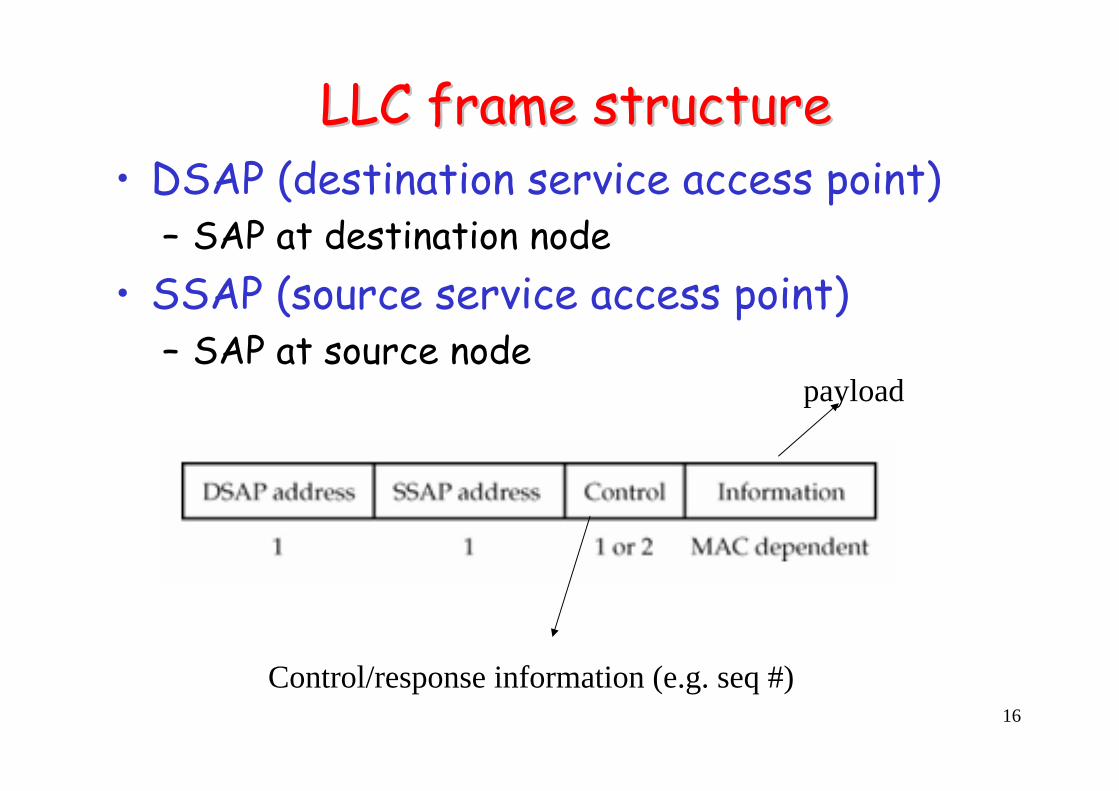
LLC frame structureLLC frame structure• DSAP (destination service access point)
– SAP at destination node• SSAP (source service access point)
– SAP at source node
Control/response information (e.g. seq #)
payload

17
802.11: L2/L1 Protocol Stack802.11: L2/L1 Protocol Stack
Logical link control
Distributed coordination function(DCF)
Point coordination Function(PCF)
2.4-Ghzfrequency-
hoppingspread
spectrum1 Mbps2 Mbps
2.4-Ghzdirect
sequencespread
spectrum1 Mbps2 Mbps
Infrared1 Mbps2 Mbps
5-GhzOFDM
6, 9, 12,18, 24, 36,
48, 54 Mbps
2.4-Ghzdirect
sequencespread
spectrum5.5 Mbps11 Mbps
Contention-freeservice Contention
service
IEEE 802.11 IEEE 802.11a IEEE 802.11b
MAClayer
2.4-GhzOFDM
6, 9, 12,18, 24, 36,
48, 54 Mbps
IEEE 802.11g

802.11 PHY802.11 PHY

19
The The ““PHYPHY”” LayerLayer• Multiple physical layers
– First offering:• 2.4 GHz 802.11 Frequency Hopping Spread Spectrum (FHSS)
for 1-2 Mbps• 2.4 GHz 802.11 Direct Sequence Spread Spectrum (DSSS) for
1, 2, 5.5 and 11 Mbps widely used– Emerging High Speed WLAN – exciting future:
• 5 GHz 802.11 uses Orthogonal Frequency Division Multiplexing (OFDM) 802.11a
• 2.4 GHz uses OFDM 802.11g• Not widely used:
– 802.11 Diffused Infrared (DFIR)• Note, same MAC layer but all 802.11, 802.11a and
802.11b all are incompatible at the physical layer!– Multi-mode backward compatibility in the integrated
wireless NICs

20
Overlapping Frequency channels for the Overlapping Frequency channels for the 2.4GHz DSSS2.4GHz DSSS

21
DSSS PLCP PDU (long preamble)DSSS PLCP PDU (long preamble)• Sync: fixed pattern for synchronization
– Alternating 1 and 0• SFD: define the beginning of PLCP
– 1111001110100000• Signal: data rate• Service: reserved• Length: in microseconds• FCS: CRC code

22
DSSS PLCP PDU (short preamble)DSSS PLCP PDU (short preamble)• Short preamble PLCP
– Reduce preamble transmission time• Shorter (56 bits) SYNC• 2 Mbps for the 4 other fields

802.11 MAC: contention 802.11 MAC: contention resolutionresolution

24
802.11: Random 802.11: Random BackoffBackoff• Backoff Time = random() * Slot_Time
– Slot_Time is a PHY layer parameter • (e.g. 20 μs in 802.11-1999 DSSS PHY)
– random() is a random integer number drawn uniformly from [0,CW]• CW is the contention window size• CWmin≤CW ≤CWmax
– CWmin and CWmax are PHY-dependent parameters • E.g. 802.11-1999 DSSS PHY
– CWmin=31; CWmax=1023

25
802.11: Contention Window802.11: Contention Window• Increment of CW
– In 802.11, CW=2n-1– Initialization, CW=CWmin– CW increase with every
retry– CW increases up to CWmax
• (truncated) binary exponential backoff
Example: CWmin=7, CWmax=255

26
MAC Layer FunctionalityMAC Layer Functionality• MAC Sublayer
– Format of messages (data and control) – Access control/mechanisms
• contention mode– For access to the channel by multiple contending devices
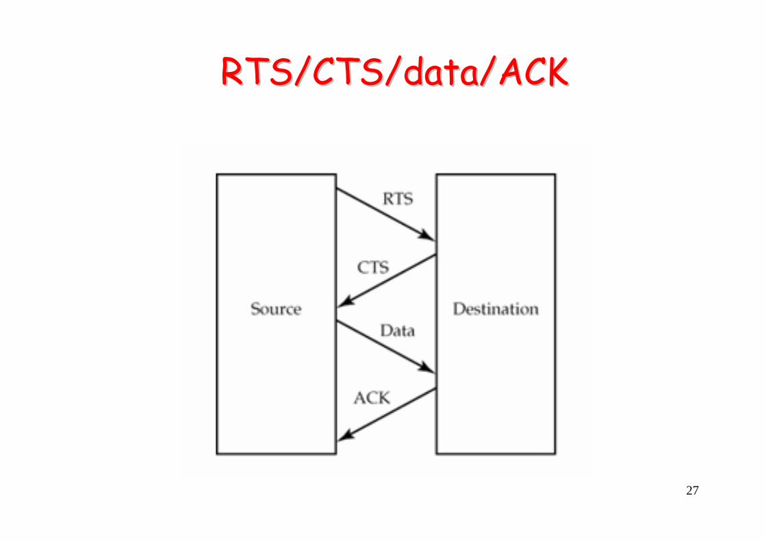
• contention-free schemes – RTS/CTS, DATA and PCF for time bounded access
• MAC layer management sublayer– Roaming support in the ESS, power management and security
• After transmission of a packet all mobiles wait for one of three devices IFS (inter-frame spacings) according to the level of priority of their packet– DCF-IFS (DIFS) used for contention, lowest priority, longest delay– Short-IFS (SIFS) used for high priority such as ACKs, CTS, etc. has
the lowest duration time– PCF-IFS (PCF) has second priority rate with duration between DIFS
and SIFS
27
RTS/CTS/data/ACKRTS/CTS/data/ACK

28
RTS and CTS framesRTS and CTS frames

29
RTS/CTS/data/ACK, SIFS, and NAVRTS/CTS/data/ACK, SIFS, and NAV
NAV: Network Allocation Vector
SIFS (Short Interframe Space)

30
RTS/CTS/data/ACK and DIFSRTS/CTS/data/ACK and DIFS
DIFS (Distributed Interframe Space)

31
CSMA/CA CSMA/CA BackoffBackoff
Backoff = random_time(x)
0≤ random_time(x) ≤ collision window

32
Prioritize Prioritize IFSsIFSs• interframe spacing (IFS)
– SIFS: short IFS– PIFS: point (coordinated function) IFS
• PCF IFS– DIFS: distributed (coordinated function) IFS
• DCF IFS– EIFS: extended IFS
• SIFS < PIFS< DIFS < EIFS

33
RTS (20 Bytes) /CTS (16 Bytes) MechanismRTS (20 Bytes) /CTS (16 Bytes) Mechanism• Toggling the NAV
– Hear an RTS• Switch NAV on• CTS• DATA
• Hear the ACK– Switch NAV off
• This provides contention free transmission

34
MAC StateMAC StateDiagramDiagram

35
CSMA/CA with ACK in an CSMA/CA with ACK in an Infrastructure NetworkInfrastructure Network
• RTS/CTS could be turned off– Only CSMA/CA

802.11 MAC frame structure802.11 MAC frame structure

37
MAC Frame structureMAC Frame structure
bits

38
Type/SubtypeType/Subtype• Management Type (00)
– Assoc. request/response– Reassoc. request/response– Probe-request/response– Beacon– Announcement traffic indication (used for sleep mode operations)– Authentication/Deauthentication
• Control Type (01)– Power save poll– RTS/CTS– Ack– CF end and CF end with ACK
• Data Type (10)– Data/ Data with CF ACK– Data Poll with CF/ Data Poll with CF and ACK– CF poll/ CF poll CK

39
Example: Type/Subtype in frame Example: Type/Subtype in frame control field (within MAC header)control field (within MAC header)
Data0000Data10
ACK1101Control01
CTS1100Control01
RTS1011Control01
Association response
0001Management00
Association request
0000Management00
Message Description
Subtype (4 bits)Type Description
Type (2 bits)

40
Control message formatControl message format
RTS(20 bytes)
CTS(16 bytes)
ACK(14 bytes)

41
RTSRTS• FCS frame check sequence = 32-bit CRC• RA: receiver address
– Data/RTS receiver• TA: transmitter address
– Data/RTS transmitter• Duration
– Microseconds• Round up to the higher integer
– T=data_tim+CTS_time+ACK_time+SIFS *3
Do you know why?

42
CTSCTS• FCS frame check sequence = 32-bit CRC• RA: receiver address
– CTS receiver (i.e. data transmitter)– Copy from TA in RTS message
• Duration– Microseconds
• Round up to the higher integer– T=data_tim+ACK_time+SIFS *2
= (Duration in RTS) – SIFS – CTS_time

43
ACKACK• RA: receiver address
– ACK receiver (i.e. data transmitter)• Duration
– Microseconds• Round up to the higher integer
– T=ACK_time+SIFS
802.11 Coordinated Functions: 802.11 Coordinated Functions: DCF and PCFDCF and PCF

45
802.11: Coordinated Functions802.11: Coordinated Functions• 2 types of coordinated functions
– DCF: distributed coordinated function– PCF: point Coordination Function
• Built upon DCF• Optional
– Not always implemented in products• Centralized coordination
– More like cellular BS
46
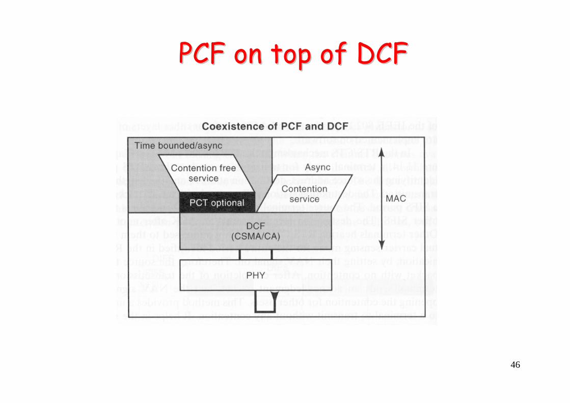
PCF on top of DCFPCF on top of DCF

47
PCF (Point Coordination Function) ModePCF (Point Coordination Function) Mode• Built of top of DCF
– Supports contention-free, time bounded and asynchronous transmission operations
– Optional MAC function/feature – not widely available in products– Mostly available as part of infrastructure mode with an AP, which
can be set up as a central coordinator (like BS in cellular)• Operation in PCF mode
– AP polls devices periodically– Sets up contention-free period (CFP)– Coordinates time bounded data to be transmitted in each CFP– During that period when a device is transmitting data PCF sets all
the NAV signals ON at all other stations – Length of PCF period is variable and only occupies a potion of the
CFP– The remainder of the CFP is used for contention and DCF packets– If DCF has not completed before the start of the next CFP period,
the starting time of the CFP is deferred but NAV is turned ON

48
PCF: PCF: pollablepollable stationsstations• Pollable station
– Able to respond to CF-Poll in PCF mode• A node in PCF mode that has MSDU (MAC SDU) to
transmit in contention-free period– Set More Data field = 1 to notify the point
coordinator• Piggyback control messages are allowed
– CF-ACK and CF-Poll could be piggybacked after data transmission. For example,
• Data+CF-Poll• Data+CF-ACK• Data+CF-ACK+CF-Poll

49
PCF time framesPCF time frames• Two periods
– Contention free interval– Contention interval

50
MAC Timing: PCF OperationMAC Timing: PCF Operation

51
Alternation of ContentionAlternation of Contention--Free and contention Free and contention periods under PCF control from the APperiods under PCF control from the AP

802.11: other functions802.11: other functions
53
MAC Management Sublayer FunctionsMAC Management Sublayer Functions
• Registration• Handoff • Power Management• Security

54
RegistrationRegistration• Beacons sent periodically (every 100ms) by AP to
establish time sync. (TSF) and maintain connectivity or associations– contains BSS-ID used to identify the AP and network,
traffic indication map (for sleep mode), power management, roaming
– RSS measurements are based on the beacon message• AP and mobile devices form “associations”, mobile
device “registers” with AP. • Mobiles send “requests” and APs “responses”• Only after registering can mobiles send/receive
DATA

55
Association ProcedureAssociation Procedure
1. Association Request
2. Association Response
3. Traffic

56
ReRe--association with old APassociation with old AP
3. Reassociation Exchange1. Move
2. Move back

57
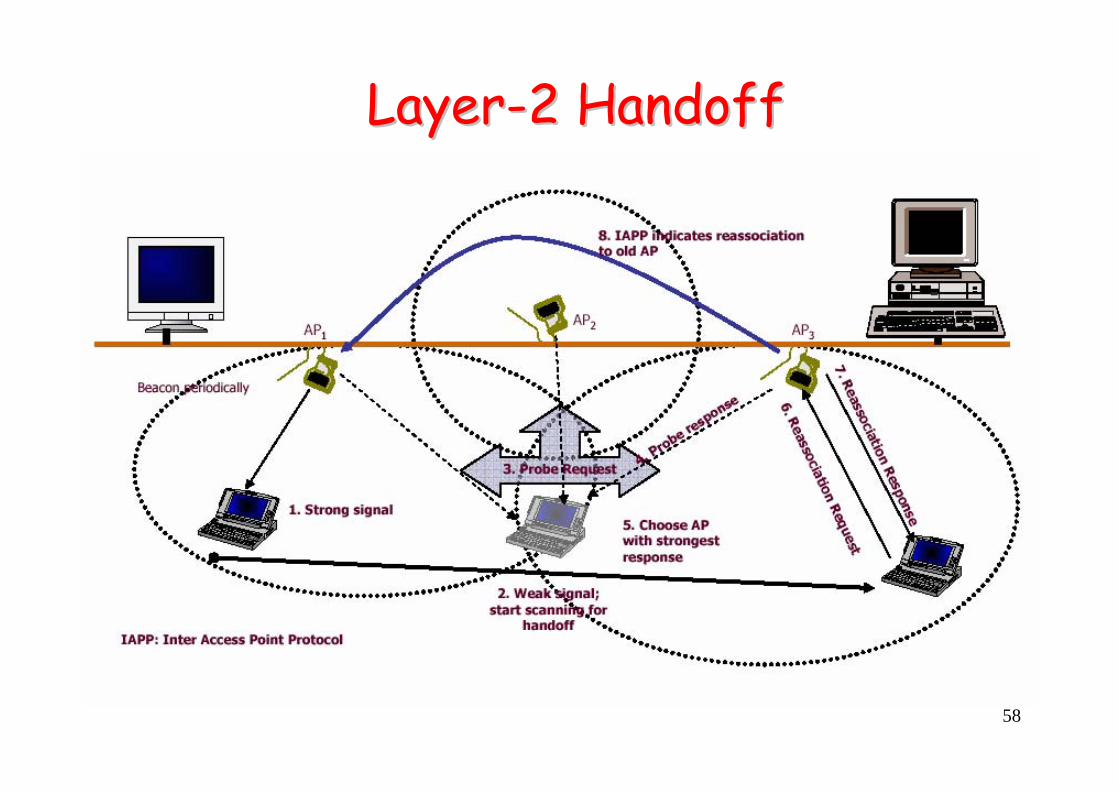
Roaming between Roaming between APsAPs• IAPP ( Inter Access-Point Protocol )
– 802.11f• Layer-2 handoff in 802.11 networks
– Topic of research• Reduce L2 handoff latency• Integrate with L3 handoff to improve overall
handoff performance– Issues
• Security: authentication• Scanning channels (multiple possible channels)
58
LayerLayer--2 Handoff2 Handoff

59
Power Management OverviewPower Management Overview• Why power management?
– Most of the time mobile devices receive data in burst and then are idle for the rest of the time.
– Can exploit that by going into a power saving idle mode – “powering off”. However, need to maintain on-going sessions
• Basic idea– Mobile sleeps, AP buffers downlink data, and sends the data when
the mobile device is awakened– Using the Timing Sync Function all mobiles are synchronized and
they will wake up at the same time to listen to the beacon. • Check the beacon to see if the mobile needs to wake up
• Compare to cellular network power control– In comparison to the continuous power control in cellular networks
this power conservation is geared towards burst data

60
Power Management in 802.11Power Management in 802.11• MS has 2 modes
– Active mode (AM)– power-save (PS) mode
• MS enters power-save (PS) mode– Notify AP with “Power Management bit” in
Frame Control field– PS mode MSs listen for beacons periodically
• MS enters active mode– The MS sends a power-save poll (PS-Poll) frame
to the AP and goes active

61
Power Management in 802.11Power Management in 802.11• AP operations (when MS is in PS mode)
– Does not arbitrarily sends MSDU to MS in PS mode– Buffer MSDUs at AP until MS “wake up”– MSs with buffered MPDUS at AP are identified with
traffic indication map (TIM).• TIM is included in periodic beacons• MS learns that it has data buffered by checking the
beacon/TIM
• AP operations when MS goes into active mode– The AP then sends the buffered data to the mobile in
active mode

62
Concept: Paging and Sleep modeConcept: Paging and Sleep mode• Sleep mode (dormant mode)
– Save power• Wake up mechanism
– Paging• Combine with location management mechanism (in
cellular networks not in 802.11)– Paging area V.S. location area– Frequency of location area update– Savings
• Power consumption• Signaling overhead
• Paging + IP IP Paging

63
Listening to the beacon for power Listening to the beacon for power managementmanagement

64
Security: Two schemes supportedSecurity: Two schemes supported• Open system authentication is default
– AP and mobile use a shared key that they exchange as a request/response
– Sends the “key” using a 40-bit secret code that is shared by the AP and mobile
• Wired Equivalent Privacy (WEP)– Pseudo random generator is used along with a
40-bit secret key to create a key sequence that is simply XOR-ed with the message
– Susceptible to attacks

65
802.11i: Security Enhancement802.11i: Security Enhancement• WEP security is weak• 802.11i standard for better security
– Authentication• Authentication protocol
– EAP (Extensible Authentication Protocol)• Authentication Server
– RADIUS (Remote Authentication Dial-In Service) server– Data privacy (encryption)
• 128-bit AES keys• 104-bit RC4 keys
– WEP uses 40-bit RC4
• Wi-Fi Protected Access (WPA)

66
802.11i service flow802.11i service flow

67
QoS Enhancement for 802.11QoS Enhancement for 802.11• IEEE 802.11e
– Enhanced DCF (EDCF), to provide service differentiation
• Traffic Classes (TC)– Give priorities to different TCs– Multiple prioritized queues
• Assign different CWmin values to different traffic classes• Assign an Arbitration IFS (AIFS) instead of DIFS, to
different traffic classes, resulting in smaller AIFS values for high priority classes
• Transmit Opportunity (TXOP)– “time” window to send as many packets as possible– Avoid low-rate nodes use excessive amount of resources
• Wi-Fi Multimedia (WMM) certified products– Hybrid coordination function (HCF) to replace PCF.

68
Access CategoriesAccess Categories

69
IFSIFSDifferent AIFS for different traffic classes

70
SSoome other interesting 802.11 standardsme other interesting 802.11 standards• IEEE 802.11i - Enhanced security• IEEE 802.11n - Higher throughput
– High-rate PHY • MIMO
• IEEE 802.11s - ESS Mesh Networking– L2 WLAN mesh