Embed Size (px)
Citation preview

OCEAN DRILLING PROGRAM
LEG 186 PRELIMINARY REPORT
WESTERN PACIFIC GEOPHYSICAL OBSERVATORIES
Dr. I. Selwyn Sacks Dr. Kiyoshi SuyehiroCo-Chief Scientist Co-Chief Scientist
Carnegie Institution of Washington Ocean Research InstituteDepartment of Terrestrial Magnetism The University of Tokyo
5241 Broad Branch Road, N.W. 1-15-1 MinamidaiWashington, D.C. 20015-1305 Tokyo 164-8639, Japan
U.S.A.
Dr. Gary D. ActonStaff Scientist
Ocean Drilling ProgramTexas A&M University Research Park
1000 Discovery DriveCollege Station, Texas 77845-9547
U.S.A
_______________________ _______________________Dr. Jack Baldauf Dr. Gary D. ActonDeputy Director Leg Project Managerof Science Operations Science ServicesODP/TAMU ODP/TAMU
September 1999
ark,
re
This informal report was prepared from the shipboard files by the scientists who participated inthe cruise. The report was assembled under time constraints and is not considered to be a formalpublication which incorporates final works or conclusions of the participating scientists. Thematerial contained herein is privileged proprietary information and cannot be used forpublication or quotation.
Preliminary Report No. 86
First Printing 1999
Distribution
Electronic copies of this publication may be obtained from the ODP Publications Homepage onthe World Wide Web at http://www-odp.tamu.edu/publications.
D I S C L A I M E R
This publication was prepared by the Ocean Drilling Program, Texas A&M University, as anaccount of work performed under the international Ocean Drilling Program, which is managedby Joint Oceanographic Institutions, Inc., under contract with the National Science Foundation.Funding for the program is provided by the following agencies:
Australia/Canada/Chinese Taipei/Korea Consortium for the Ocean DrillingDeutsche Forschungsgemeinschaft (Federal Republic of Germany)Institut Français de Recherche pour ['Exploitation de la Mer (France)Ocean Research Institute of the University of Tokyo (Japan)National Science Foundation (United States) Natural Environment Research Council (United Kingdom)European Science Foundation Consortium for the Ocean Drilling Program (Belgium, Denm
Finland, Iceland, Italy, The Netherlands, Norway, Spain, Sweden, and Switzerland) Marine High-Technology Bureau of the State Science and Technology Commission of the
People's Republic of China
Any opinions, findings, and conclusions or recommendations expressed in.this publication athose of the author(s) and do not necessarily reflect the views of the National ScienceFoundation, the participating agencies, Joint Oceanographic Institutions, Inc., Texas A&MUniversity, or Texas A&M Research Foundation.

Leg 186 Preliminary Report 3
The following scientists were aboard JOIDES Resolution for Leg 186 of the Ocean DrillingProgram:
I. Selwyn SacksCo-Chief ScientistDepartment of Terrestrial MagnetismCarnegie Institution of Washington5241 Broad Branch Road, N.W.Washington, DC 20015-1305U.S.A.Internet: [email protected]: 202-686-4370, ext. 4388Fax: 202-364-8726
Kiyoshi SuyehiroCo-Chief ScientistDeep Sea Research DepartmentJAMSTEC2-15 Natsushima-choYokosuka 237-0061JapanInternet: [email protected]: 81-468-67-3827Fax: 81-468-66-5541
Gary D. ActonStaff ScientistOcean Drilling ProgramTexas A&M University1000 Discovery DriveCollege Station, TX 77845U.S.A.Internet: [email protected]: 409-845-2520Fax: 409-845-0876
Michael J. AciernoDownhole Tools SpecialistDepartment of Terrestrial MagnetismCarnegie Institution of Washington5241 Broad Branch Road, N.W.Washington, DC 20015U.S.A.Internet: [email protected]: 202-686-4370, ext. 4380Fax: 202-364-8726
Eiichiro ArakiPhysical Properties SpecialistOcean Research InstituteUniversity of Tokyo1-15-1 Minimidai, Nakano-kuTokyo 164-8639JapanInternet: [email protected]: 81-3-5351-6538Fax: 81-3-5351-6438
Maria V.S. AskJOIDES Logging Scientist/Physical PropertiesSpecialistGeologi och GeokemiStockholms UniversitetStockholm SE-106 91SwedenInternet: [email protected]: 46-8-16-47-69Fax: 46-8-674-78-16
Akihiro IkedaPaleontologist (diatoms)Department of Earth and Planetary SciencesGraduate School of SciencesHokkaido UniversityN10W8Sapporo, Hokkaido 060-0810JapanInternet: [email protected]: 81-11-716-2111, ext 3519Fax: 81-11-746-0394
Toshiya KanamatsuPaleomagnetistDeep Sea Research DepartmentJapan Marine Science and Technology Center2-15 Natsushima-choYokosuka, Kanagawa 236-0061JapanInternet: [email protected]: 81-468-67-3832Fax: 81-468-66-5541
4 Leg 186 Preliminary Report
s
Gil Young KimPhysical Properties SpecialistDepartment of Applied GeologyPukyong National University599-1 Dayeon-Dong, Nam-GuPusan 608-737South KoreaInternet: [email protected]: 82-51-620-6233Fax: 82-51-623-5068
Jingfen LiPaleontologist (nannofossils)Department of GeologyFlorida State University108 Caraway BuildingTallahassee, FL 32306-4100U.S.A.Internet: [email protected]: 850-644-5860Fax: 850-644-4214
Alan T. LindeJOIDES Logging Scientist/Physical Properties
SpecialistDepartment of Terrestrial MagnetismCarnegie Institution of Washington5241 Broad Branch Road, N.W.Washington, DC 20015U.S.A.Internet: [email protected]: 202-686-4370, ext 4394Fax: 202-364-8726
Paul N. McWhorter Downhole Tools SpecialistDepartment of Terrestrial MagnetismCarnegie Institution of Washington5241 Broad Branch Road, N.W.Washington, DC 20015U.S.A.Internet: [email protected]: 202-686-4370, ext 4406Fax: 202-364-8726
Germán MoraOrganic GeochemistDepartment of Geological SciencesIndiana University, Bloomington1005 East 10th StreetBloomington, IN 47405U.S.A.Internet: [email protected]: 812-855-1382Fax: 812-855-7961
Yanina M.R. NajmanSedimentologistDepartment of Geology and GeophysicUniversity of EdinburghKings BuildingsWest Mains RoadEdinburgh EH9 3JWUnited KingdomInternet: [email protected]: 44-131-650-8511Fax: 44-131-668-3184
Nobuaki NiitsumaPaleomagnetistInstitute of GeosciencesShizuoka University836 OyaShizuoka 422-8529JapanInternet: [email protected]: 81-54-238-4787Fax: 81-54-238-0491
Ericka J. OlsenUndergraduate Student TraineeDepartment of GeologyUniversity of Pennsylvania240 South 33rd St.Philadelphia, PA 19104-6316U.S.A.Internet: ericka @sas.upenn.eduWork: (215) 898-5724Fax: (215) 898-0964

Leg 186 Preliminary Report 5
Benoy K. PanditDownhole Tools SpecialistDepartment of Terrestrial MagnetismCarnegie Institution of Washington5241 Broad Branch Road, N.W. Washington, DC 20015U.S.A.Internet: [email protected]: 202-686-4370, ext 4408Fax: 202-364-8726
Sybille RollerSedimentologistGeologisches InstitutUniversität FreiburgAlbertstrasse 23BFreiburg D-79104GermanyInternet: [email protected]: 49-761-203-6492Fax: 49-761-203-6496
Saneatsu SaitoLDEO Logging ScientistOcean Research InstituteUniversity of Tokyo1-15-1 Minamidai, Nakano-kuTokyo 164JapanInternet: [email protected]: 81-3-5351-6559Fax: 81-3-5351-6438
Tatsuhiko SakamotoSedimentologistDepartment of Earth and Planetary SciencesHokkaido UniversityKita-10, Nishi-8, KitakuSapporo, Hokkaido 060-0810JapanInternet: [email protected]: 81-11-706-2726Fax: 81-11-746-0394
Masanao ShinoharaPhysical Properties SpecialistEarthquake Research InstituteUniversity of TokyoYayoi 1-1-1, Bunkyo-ku113-0032 TokyoJapanInternet: [email protected]: 81-43-290-2849Fax: 81-43-290-2859
Yue-Feng SunLDEO Logging ScientistLamont-Doherty Earth ObservatoryColumbia UniversityBorehole Research GroupPalisades, NY 10964U.S.A.Internet: [email protected]: 914-365-8504Fax: 914-365-3182

6 Leg 186 Preliminary Report
Leg 186 Preliminary Report 7
5
ed by
g rate
c
s
of the
.y. The
water
area
e
a at Site
are
4.
lts
ormal
al
from the
cross
SCIENTIFIC REPORT
ABSTRACT
Two borehole geophysical observatories were installed ~1100 m below the seafloor on
the deep-sea terrace of the Japan Trench during Ocean Drilling Program Leg 186. Site 1150
(39E11NN, 143E20NE) and Site 1151 (38E45NN, 143E20NE) are located in areas with contrasting
seismic characteristics. The northern site is within a seismically active zone where
microearthquakes are frequent and M7 earthquakes recur. The southern site is within an aseismic
zone where no earthquakes are observed. These features coexist within the seismogenic zone of
the Japan Trench plate subduction zone, where the >100-Ma portion of the Pacific plate is
subducting at a fast rate (~8 cm/yr) beneath northern Japan causing major earthquakes along the
trench. Such a dynamic nature of the subduction seismogenic zone remains unexplained because
no geodetic and few seismic stations exist on the seafloor that give us hard evidence in the
vicinity of the fault (décollement) zone. Leg 186 is the first scientific venture to succeed in
installing state-of-the-art strain, tilt, and seismic sensors for long-term operation in seafloor
boreholes. The borehole instruments were installed only 10 km above the gently dipping (<E)
plate boundary. The systems will start collecting data in September 1999 and will be servic
a remotely operated vehicle (ROV) at least once a year to recover continuous high samplin
and wide dynamic range data. These stations will make invaluable additions to the existing
geophysical network over the western Pacific. This type of multiple-sensor seismo-geodeti
observatory can now be emplaced by the JOIDES Resolution at many other areas where active
processes await to be monitored.
Previous drilling in the area took place during Deep Sea Drilling Project (DSDP) Leg
56, 57, and 87, which transected the Japan Trench at ~39.8EN–40.7EN. These legs established
the concept of tectonic erosion along a subduction zone. The Neogene subsidence history
forearc was documented and numerous ash records were obtained that span the past 9 m
coring and logging data obtained from Sites 1150 (2681-m water depth) and 1151 (2182-m
depth) provide additional observations to further our understanding of the tectonics of this
with better recovery and higher resolution than was available from previous drilling along th
Japan Trench. The ages of the recovered sediments are 10–0 Ma at Site 1150 and 16–0 M
1151. The sedimentation rates significantly differ before ~7 Ma between the two sites, but
similar since then, and are similar to the rates at DSDP Leg 57 Site 438 and Leg 87 Site 58
Estimations on the deformational history from observed microfractures and microfau
and logging data are consistent with a general east-west extensional stress field in which n
faulting dominates. It will be of great interest to compare these structural data and addition
mechanical properties measurements to be made on whole-round core samples with data
observatories, where the current tectonic stress field is actually east-west compressional a
the Japan arc to the Sea of Japan.
8 Leg 186 Preliminary Report
re
hich was
linity
nd 439
en the
r
led in
ing
pt to
re and
eans
es and
LE,
a few
ermal
ve
eservoirs
a
g
ost of
ic
n. In
mic and
al
Recovering detailed ash records was one of the highlighted drilling objectives. As with
previous drilling results, a general increase from ~9 Ma and a peak in the past 0.5–4 Ma a
observed at the two sites. Postcruise studies will examine the details of the ash record, w
more completely recovered on Leg 186 than on previous cruises.
Inorganic geochemical analysis confirmed that a large decrease in chlorinity and sa
with depth exists in the Japan Trench region. This was first observed at DSDP Sites 438 a
but not at other sites of Legs 56 and 57. The character of the anomalies varies also betwe
two ODP Leg 186 sites. Overall, the magnitude of decrease seems much larger than othe
subduction environments such as at Nankai or Barbados.
To further our understanding of the plate subduction dynamics, near-site multiple
disciplinary investigations are clearly needed. In particular, geological “hysteresis” concea
present-day dynamics needs to be better understood to construct physical models by link
geological/geochemical and geophysical studies. Leg 186 is one such investigative attem
link current and past dynamics by establishing borehole observatories and by obtaining co
logging data at the seismogenic zone of the Japan Trench.
INTRODUCTION
The scientific importance of establishing long-term geophysical stations in deep oc
has been acknowledged by earth sciences and Ocean Drilling Program (ODP) communiti
is expressed in various articles (COSOD II, 1987; Purdy and Dziewonski, 1988; BOREHO
1994; Montagner and Lancelot, 1995; Ocean Drilling Program, 1996). Indeed, more than
important inferences on the dynamics of the Earth’s deep interior have been inferred from
seismic tomography images, such as existence of super plumes, deep continental roots,
stagnation of subducting plates within the mantle, and variations in the thickness of the th
boundary layer at the base of the mantle (e.g., Fukao, 1992). Detailed examination of acti
processes at plate boundaries have also brought about significant inferences on magma r
at oceanic ridges and on the décollement structure of subducting plates.
In essence, we wish to understand active processes driving Earth’s dynamics from
global to a regional scale. A major step forward will almost certainly be made by installing
permanent observatories in the oceans, which constitute 71% of Earth’s surface. Obtainin
observations from oceanic areas is significant not only for global coverage, but because m
the plate boundaries exist beneath the oceans, particularly those boundaries where ocean
lithosphere is presently being generated and recycled.
The western Pacific area is ideal for addressing problems related to plate subductio
particular, the Japan Trench area is where much effort has been made for monitoring seis
geodetic motions on land for many years. Together with marine geological and geophysic
investigations on both sides of the Japan island arc, this area probably is the best studied
Leg 186 Preliminary Report 9
subduction area. The area can be characterized as having a fast subduction rate and being a
seismically active and well-coupled area. We also have knowledge of the sedimentary and
tectonic environment from previous drilling, which found the forearc area to be subsiding as a
result of tectonic erosion with little accretionary prism development.
To monitor strain and seismic activity continuously and ultimately to understand how
plate motion is accommodated across a subduction zone, we have installed two geophysical
observatories on the landward side of the Japan Trench (Fig. 1). Coring and logging data
collected during the cruise are also expected to provide a tectonic history that can be linked to the
present dynamics, which will be inferred from the observatories.
Although not always the case, normal coring objectives and observatory objectives often
overlap and are interrelated as in this leg or recent Circulation Obviation Retrofit Kit (CORK)
legs. Once an observatory is established, ways and means to recover the data and to keep the
station running become necessary. Such tasks are not easily undertaken even if a site only needs
servicing once a year. A new fiber-optic cable owned by the University of Tokyo already exists
and currently terminates near Site 1150. Once Site 1150 proves to be functioning, connections
will be made to supply power, send commands, and retrieve data in real time on land.
Furthermore, a 50-km cable extension is planned to connect Site 1151 as well. These stations
will make invaluable additions to the existing geophysical network over the western Pacific. The
data will eventually become accessible worldwide through the Internet.
PREVIOUS DRILLING ALONG THE JAPAN TRENCH
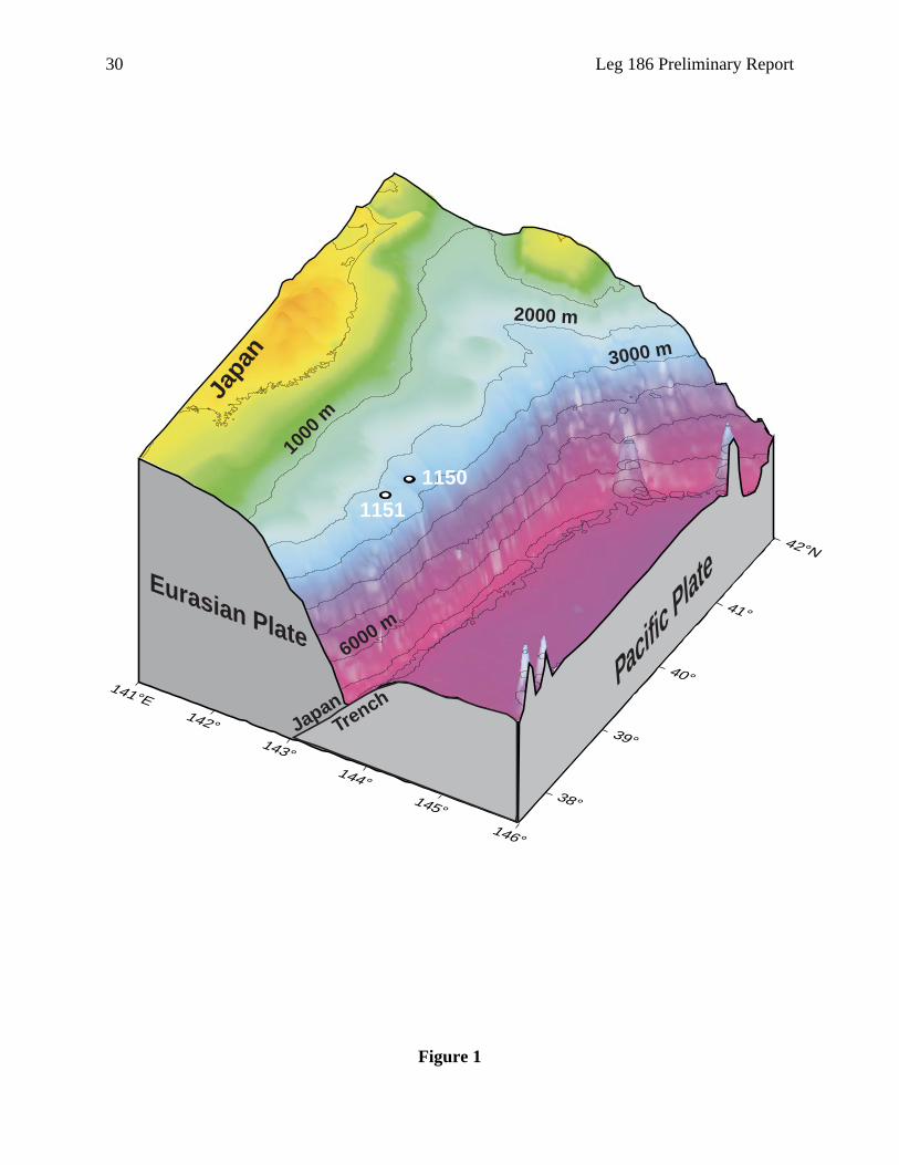
Previous deep-sea drilling sites along the Japan Trench are shown in Figure 2. During
DSDP Legs 56 and 57, Sites 436 (Leg 56), 434 (Leg 56), 441, 440, and 435 (Leg 56) were drilled
along seismic Line JNOC-2 across the trench at 39E45NN. Sites 438 and 439 were drilled along
seismic Line JNOC-1 across the trench at 40E40NN (Scientific Party, 1980). During DSDP Leg
87, Site 584 was also drilled in the area (Kagami, Karig, Coulbourn, et al., 1986). These legs
were focused to study the mechanism and dynamics of plate convergence and their effects on
sedimentation. It is presently widely accepted that little tectonic accretion is occurring. Instead, a
massive subsidence has been taking place along the Japan Trench. This was a surprising finding
substantiated by past drilling. Another surprise was the unexpected discovery of andesitic
volcanic rocks from Site 439, 90 km from the trench axis, which indicated that there is an offset
of ~200 km between the present arc and where Oligocene volcanism occurred.
The Cretaceous unconformity widely recognized on land was observed at Site 439 and
could be further extrapolated seaward by the aid of seismic records suggesting that a pre-
Oligocene forearc once extended at least to the present midslope terrace where Site 440 is
located. The objective at Site 584 was to further confirm and detail the findings of Legs 56 and
57. Site 584, at the outer slope, reached sediment of middle Miocene age, confirming persistent
10 Leg 186 Preliminary Report
subsidence during the Miocene. It was suggested that extensional tectonics continued from the
middle Miocene until the early Pliocene. Numerous ash layer records from all the sites suggest
that onshore volcanic activity increased near the end of the late Miocene and continued through
the early Pliocene.
Leg 186 was planned to establish borehole geophysical observatories that could monitor
the ongoing tectonic processes and confirm and detail previous findings at two sites (Sites 1150
and 1151) ~25 km north and south of 39EN, corresponding to slightly seaward of Site 439 in
longitude.
TECTONIC AND SEISMIC SETTING
Tectonic Setting
The convergent margin off northern Honshu has developed where lower Cretaceous
Pacific ocean crust underthrusts the Eurasian plate in a westerly direction. A 10.5 cm/yr
convergence rate between these two plates has been estimated (e.g., Wesnousky et al., 1982).
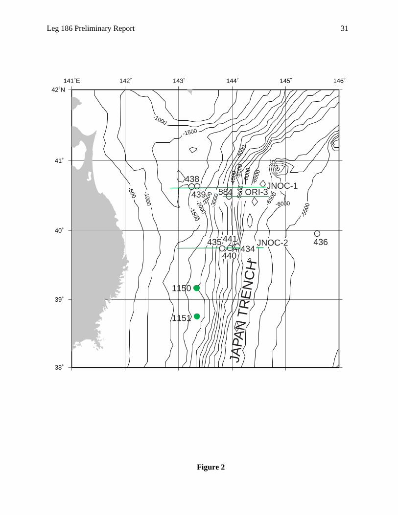
The topographic features of the Japan Trench system consist of deep-sea terrace, inner trench
slope, midslope terrace, trench lower slope, Japan Trench, and outer trench slope (Fig. 3). A
forearc basin develops in the deep-sea terrace and trench upper slope, which extends from the
northwest coast of Hokkaido more than 600 km to the south and is filled with Neogene
sediments as much as 5 km thick. Sites 1150 and 1151 on the deep-sea terrace, located ~100 km
west of the Japan Trench, are on the eastern edge of the forearc basin, where the Neogene section
is ~1.5 km thick.
In multichannel seismic profiles, the reflective sequence above a major diffracting
horizon represents a seaward transgressive sequence across an extensive angular unconformity
(Fig. 4). Landward-dipping reflectors below the unconformity may represent formerly accreted
sediments or folded and tilted older sedimentary rocks; they are dated by drilling as Upper
Cretaceous at Site 439. The Neogene sequence is cut by landward-dipping normal faults spaced
~10 to 15 km apart (Nasu et al., 1980). Seismic refraction measurements indicate a continental
crustal velocity structure beneath the deep-sea terrace (Murauchi and Ludwig, 1980; Suyehiro
and Nishizawa, 1994).
Tectonic history in the convergent margin near the Japan Trench is characterized by
tectonic subsidence and erosion. Regional subsidence during the latest period of plate
convergence was established during DSDP drilling along the Japan Trench margin (von Huene,
Nasu, et al., 1978) by coring through a subaerial erosion surface many kilometers below sea level
(Fig. 5). That erosion surface corresponds to an angular unconformity that cuts across tilted beds
and is buried beneath subhorizontal strata of the outer shelf and slope. The unconformity extends
throughout a 150-km-long area (Nasu et al., 1980; von Huene et al., 1982) and shows no sign of
ending beyond the published seismic coverage. Across the unconformity, seismic velocity
increases abruptly from ~1.9 to 4.2 km/s (Murauchi and Ludwig, 1980; Suyehiro and Nishizawa,
Leg 186 Preliminary Report 11
he
i et
the
d
1994), consistent with the contact between unconsolidated Oligocene to Quaternary strata and
well-consolidated Cretaceous rock as drilled at DSDP Site 439. The sedimentary strata above the
unconformity consist of a 48-m-thick breccia and conglomerate of dacite and rhyolite boulders,
covered by 50 m of medium-grained sand containing abundant little-transported macrofossils,
which was in turn buried by silt and sand turbidites (Scientific Party, 1980) with a probable
seaward source (von Huene et al., 1982). The upper 800 m of the section consists of Miocene
diatomaceous mud. The regional extent of rock types and erosion was explained by subsidence
of a landmass during the past 22 m.y. (Scientific Party, 1980; von Huene et al., 1982). Benthic
microfossils from the sediments indicate a succession of water depth consistent with such a
history (Arthur et al., 1980; Keller, 1980).
Seismic Setting
In the Japan Trench area, seven large (magnitude [M] = >7) interplate events have
occurred in the last 30 yr between 38EN and 41EN. Recent large events are the 1968 Tokachi-Oki
earthquake (~41EN; moment magnitude [Mw] = 7.9) and the 28 December 1994 Far-off Sanriku
earthquake (~40EN; Mw = 7.7) (Fig. 6). These events, however, are not sufficient to account for
the subducting rate of ~8–10 cm/yr. Thus, the seismic coupling seems much smaller along t
Japan Trench (35EN–41EN) as compared with the Kurile Trench or Nankai Trough regions,
which have a higher seismic energy release rate. Subduction at the Japan Trench may be
proceeding by stable sliding either only with relatively small (surface-wave magnitude [Ms] =
<8) events or with occasional large events.
There is a third important category whereby the subduction rate is accommodated by
episodic aseismic events of time constants on the order of 10 min to several days (slow
earthquakes). Such events, if they exist, are presently extremely difficult to detect. Kawasak
al. (1995) reported that an ultra-slow earthquake estimated to be Mw 7.3–7.7 accompanied
1992 Off-Sanriku (39.42EN, 143.33EE; Mw = 6.9) earthquake, based on strain records observe
~120–170 km away from the source. A postseismic strain change of 10–7 to 10–8 with a time
constant of about a day were observed by quartz-tube extensometers (devices that measure
absolute strain). Historically, in the same area, the 1896 Sanriku tsunami earthquake (Mw = ~8.5
but body-wave magnitude [Mb] = ~7) killed ~22,000 people. Tsunami earthquakes rupture in a
much longer time constant of minutes compared to normal type (Tanioka and Satake, 1996).
More recently, the Japanese global positioning system network revealed a postseismic
motion of northern Japan after the 1995 Far-off Sanriku earthquake (M = 7.2) that can be
explained by a stress diffusion model assuming slow slip on the earthquake fault (Heki et al.,
1997). A different, but previously more prevalent interpretation is that the postseismic
deformation is a result of aseismic slip at a depth extending below the seismogenic zone.
The above-mentioned large episodic events are responsible for the plate motion. There
are numerous microearthquakes, which contribute little to tectonics, but delineate the
characteristics of seismogenic zone (Fig. 7). Microearthquake activity in this area shows spatially
12 Leg 186 Preliminary Report
edge
n
dary
the
ity
is
ut
t of
d 57 in
different
and
sical
one. At
ich the
ould
than
B
ecide
se of
til Site
ns
eter
clustered occurrence over at least a few tens of years. The plate geometry from microearthquakes
suggests that a large bend occurs at ~20 km depth. The seismic activity seems to have a gap
above and below this depth along the plate boundary. The shallower activity is conspicuously
high between 39EN–41EN.
The seismic velocity structure of this area is characterized by a small accretionary w
(Fig. 3). High velocity (> 6 km/s) material reaches beneath the inner trench slope. Either a
extension of the island arc lower crust or the mantle wedge seems to meet the plate boun
where it plunges. Large thrust earthquakes in this area often initiate from the updip end of
seismogenic zone and reach beneath the coastline. It can be seen that from detailed veloc
structure models that there is no obvious correlation with the updip and downdip ends. Th
suggests that the key factors in controlling the seismic activity are not in bulk properties, b
rather in the localized properties at the well-developed décollement.
OPERATIONS STRATEGY
Previous drilling in the Japan Trench region was in the DSDP era before the adven
advanced hydraulic piston corer/extended core barrel (APC/XCB) technology (Legs 56 an
1977 and Leg 87 in 1982). Previous ODP drilling at plate subduction zones were at Izu-
Marianas, Barbados, Costa Rica, Cascadia, Nankai, and Peru margins, which span quite
subduction types. Both Sites 1150 and 1151 are located at the deep-sea terrace at 2681-
2182-m water depths, respectively.
A unique aspect of Leg 186 was the installation of two permanent borehole geophy
observatories. The installation required a complex operation that has never before been d
this environment, a clear deep-seismic reflector is the Cretaceous unconformity, below wh
physical properties such as P-wave velocities and densities become more favorable for the
sensors. However, it did not seem realistic to drill to depths of more than 1.5 s in two-way
traveltime at the two sites to penetrate the Cretaceous unconformity. Such an operation w
have required an interim supply of casing joints during the leg and considerably more time
available on a standard leg. Therefore, a provisional depth of 1000 m was targeted for RC
coring and to check if the physical properties values were acceptable for the instruments.
Logging data and observations from cores allowed us to monitor physical properties and d
on a suitable depth.
For initial coring objectives, one site with a fast sedimentation rate was to be double
APC/XCB cored to ensure complete recovery in the Pliocene and younger section. Becau
large uncertainties in installation time requirements, double APC coring was postponed un
1151.
Each site was equipped with a reentry cone and was cased through unstable sectio
leaving a 50- to 100-m open-hole section at the bottom. Because the sensor package diam
Leg 186 Preliminary Report 13
the
ary
y
ly 18
ring
ion.
just
g
of the
late
.
nd
low
n as
f the
In the
cannot run through the drill string as do logging tools, it had to be connected at the bottom of the
drill string. To cement in the sensors, which is essential for the strain measurements, the drillship
was required.
At Site 1150, the original plan for XCB coring to 450 mbsf level was deepened to 723
mbsf. Hole 1150B was thus drilled to 703 mbsf and cored to 1182 mbsf. Below ~1100 mbsf, the
physical properties seemed to be adequate for the instrument. Logging data further confirmed
and pinpointed where the instrument depth should be. The unfortunate abandonment of reentry
Hole 1150C because of probable defects in the reentry cone caused a major change of planning.
We had to go back to the port of Yokohama to obtain another reentry cone, at which time we also
loaded the remaining 4½-in casing pipes purchased for hanging the instrument package in
drilled and cased holes. At this point, we focused the use of time on accomplishing the prim
objectives for the leg, which meant that many other objectives might have to be temporaril
abandoned.
The Site 1150 installation was successfully completed at 1900 hr on July 28, with on
days left for operations at the second site. It was then that we decided to skip APC/XCB co
and logging and instead aim for the shortest pathway to complete the observatory installat
Thus, Hole 1151A was RCB cored all the way to 1114 mbsf. The operations at Hole 1151B
proceeded rapidly, and we successfully completed the instrument installation on August 9,
12 days after arriving on site. After the installation, we proceeded to complete the remainin
objectives for the hole, which included double APC coring this site to ~100 mbsf, and then
logging to 870 mbsf.
SCIENTIFIC OBJECTIVES
The Leg 186 Scientific Party sailed out to investigate the dynamic properties of one
world’s most active plate subduction zones, the Japan Trench, where the oldest oceanic p
(>100 Ma) is subducting at a high rate (~100 km/m.y.). The drill sites were located about
midway within the Japan Trench zone, which is ~650 km long.
The prime objective of this leg was to establish two geophysical observatories that
monitor strain, tilt, and seismic waves to further our understanding of subduction dynamics
Coring and logging were aimed at gathering information about past and present tectonic a
paleoceanographic conditions.
Dynamic Sliding of the Subducting Plate and Earthquake Process
The seismic coupling efficiency of the subduction zone off Tohoku appears to be as
as 25%. This means that of the total Pacific plate motion expected, only one-quarter is see
stick-slip motion leading to thrust-type earthquakes. One possibility is that three-quarters o
motion is released as slow earthquakes, which are not recorded on normal seismographs.
14 Leg 186 Preliminary Report
d may
term
linked
tion
4).
ne.
erial,
zone
to
le to
ic
urce
e
a, 1994;
y
of the
/or
ic
many
past, sparse observations suggest that the slow strain release may consist of multiple episodes in
which each event is rather small. For this reason, installation of an instrument of the highest
achievable sensitivity is required. Any data leading to better understanding of the partitioning of
strain release into damaging “fast” events and slower events will be extremely valuable an
lend further insight into the whole earthquake process.
The plate boundary off northeast Japan fulfills three important conditions for a long-
geophysical observatory:
1. Dense geophysical networks to which our proposed observatories can be optimally
already exist on land.
2. Moderately large (M = ~7) seismic events occur frequently, and aseismic slips (slow
earthquakes) with comparable or larger magnitude are expected to occur even more
frequently.
3. Crustal and uppermost mantle structures have been well studied by reflection-refrac
seismic surveys (Suyehiro et al., 1985a, 1985b, 1990; Suyehiro and Nishizawa, 199
Earthquake Source Studies
Generally, interplate thrust earthquakes occur within a zone termed the seismogenic zo
The definition and controlling factors of this zone, however, are unclear. Temperature, mat
or pore pressure that affect the frictional state of the fault are consequences of geological
processes. But their relationship is unclear. We clearly need to define what a seismogenic
is, if we are to relate to physical properties of the interacting plates. It is critically important
know where exactly earthquakes of various sizes are occurring. At present, it is not possib
locate earthquake faults using seismic techniques with less than several hundred meters’
accuracy relative to where the faults and velocity heterogeneities are. Where a local seism
network does not exist, the accuracy is often much worse and can be more than several
kilometers in error.
The borehole geophysical observatories at Sites 1150 and 1151 will greatly improve so
location (particularly depth), and focal mechanism and rupture process determinations of th
earthquakes near the Japan Trench (Nishizawa et al., 1990, 1992; Suyehiro and Nishizaw
Hino et al., 1996). Near-field data, obtained from these observatories with the aid of ocean
bottom seismographs, will particularly improve the resolution of source mechanisms of ver
slow rupture events such as tsunami earthquakes. These earthquakes may occur seaward
updip end of normal thrust earthquakes (e.g., Tanioka and Satake, 1996).
High-Resolution Geometry of the Plate Boundary
The two stations at Sites 1150 and 1151 will be linked to the network of broadband and
very broadband seismometers on the main Japanese islands and will make a dense seism
network that is 50 km in scale. The observations of various phases of body waves from the

Leg 186 Preliminary Report 15
about
nd, and
bout
d either
on the
t 25–40
with
the
e. The
sh
ory of
, 1990;
rther
The
ysical
nd
shallow to deep earthquakes within the network will provide sufficient data to improve the
structural image of the plate boundary—in particular, the changes in physical properties
associated with tectonic erosion and seismogenesis.
Miocene and Younger Volcanic Ash Stratigraphy in the Western Pacific
The cores will represent an important reference section near Japan to compare with the
remote ash deposits already cored to the east. They will also provide important information
eruptive processes, volcanic hazards, and aspects of climate such as response to wind, sa
volcanogenic input of greenhouse and related gases (J. Natland, pers. comm., 1997).
During Leg 132, a number of rhyolitic to dacitic volcanic ash beds were recovered on
Shatsky Rise, east of Japan. Comparison with ash stratigraphy at DSDP Sites 578–580, a
halfway between Shatsky Rise and Japan, indicates that the Shatsky ash beds were derive
from Japan or the Kurile-Kamchatka arc systems and that they were carried far to the east
high-speed polar and sub-tropical jet streams (Natland, 1993). A summary appraisal is tha
eruptions in each of the past 3 m.y. produced ash that reached one or more of those sites,
~10% of these reaching Shatsky Rise in the form of discrete ash beds or pumice. Some of
eruptions were extremely large, resulting in deposits 5 to 15 cm thick, even on Shatsky Ris
last drilling in this region was during DSDP Legs 56 and 57, before the advent of hydraulic
piston coring. An important, although seriously incomplete and at times highly disturbed, a
record was recovered in Holes 438A and 440B (e.g., Cadet and Fujioka, 1980).
Subsidence History Across the Continental Slope to Constrain the Processes of Tectonic
Erosion
Quantitative estimates of the tectonic erosion process were made for the Neogene hist
the Japan Trench region based on drilling and seismic records (von Huene and Lallemand
von Huene et al., 1994). Key evidence came from DSDP Site 439. Evidence collected from
additional coring at ODP Sites 1150 and 1151, which are ~200 km south of Site 439, will fu
constrain the timing and erosion volumes in relation to backarc opening and the style of
convergence. The comparison of results between 38EN and 41EN will delineate relative changes
along the axis.
SUMMARY
Site 1150
Site 1150 is located in the deep-sea terrace on the landward side of the Japan Trench.
primary objective was to establish a borehole geophysical observatory to monitor seismo-
geodetic signals immediately above the active portion of the seismogenic zone where large
interplate thrust earthquakes recur. The first successful emplacement of a borehole geoph
observatory (NEREID-1) with a three-component strainmeter, a two-component tiltmeter, a
16 Leg 186 Preliminary Report
of
he
ts are
ded in
are
and
se the
ge
bsf
fficult
Of the
tom
nity
ruptly
ed in
200 m
M
two three-component broadband seismometers was completed on July 28. The sensing sections
are less than 11 m in length bottoming at 1120 mbsf and were cemented in the 105-m-long open
hole at Hole 1150D. Because the instrument string and battery frame could not be installed
simultaneously, the electrical connection to the downhole instruments is yet to be made. The
observatory sites will be visited by the ROV Dolphin 3K of the Japanese Marine Science and
Technology Center (JAMSTEC) between 2 and 10 September to start the systems, check the
status, and collect initial data. The observatories are designed to be serviced at least once a year.
All of the cores from 0 to 722.6 mbsf from Hole 1150A are dominated by diatomaceous silty
clay. The upper 200 m of sediment consist of interbedded diatomaceous ooze and clay, with
siliceous biogenic grains, diatoms, radiolarians, and sponge spicules occurring commonly, and
foraminifers and nannofossils rarely. Volcanic glass and siliciclastic grains are also observed in
smear slides, though they compose less than 10% of the total sediment. From 260 to ~620 mbsf,
the sediments gradually become firmer and more hemipelagic with increasing depth. Compared
with cores from the upper 200 m, volcanic ash, reworked ash layers, volcanic pebbles, thin
turbiditic sand, and silt layers are rare but present in the lower section. Below ~620 mbsf, cores
from both Hole 1150A (620–722 mbsf) and Hole 1150B (703–1181.6 mbsf) consist mainly
well-lithified diatomaceous silty claystone. Authigenic glauconitic sand is interbedded with t
dominant clayey lithology below 430 mbsf in Hole 1150A and from the start of the cored
interval (703 mbsf) at Hole 1150B. Local occurrences of detrital glauconite in minor amoun
rare within both holes. Bioturbation (Chondrites, Zoophycos, and Planolites) is abundant in Hole
1150B. A few carbonaceous layers and nodule-type accumulations are also found interbed
the largely homogeneous diatomaceous silty claystone in Hole 1150B. Volcanic ash layers
rare in this hole.
Twelve diatom zonations were identified from core-catcher samples from Holes 1150A
1150B. The age of the lowermost sediment is interpreted to be younger than 9.9 Ma, becau
first occurrence of Denticulopsis dimorpha was not observed in the studied interval. The avera
sedimentation rate is 119 m/m.y., with higher sedimentation rates (>200 m/m.y.) occurring
between 6.65–3.74 Ma and between 0.3 and 0.0 Ma. The lowest sedimentation rate occurs
between 2.0 and ~1.24 Ma (18 m/m.y.). The Pliocene/Pleistocene boundary lies at ~110 m
and Pliocene/Miocene boundary at ~500 mbsf. Datums of calcareous nannofossils were di
to determine accurately because of poor preservation and low abundance of these fossils.
11 nannofossil datums identified, seven gave ages younger than those indicated by the dia
datums.
Chemical analyses of pore waters from Hole 1150A cores show that chlorinity gradually
decreases with depth from ~550 mM at the top of the hole to 500 mM at ~200 mbsf. Chlori
concentrations remain at about this value for 350 m downhole. From ~550 mbsf, values ab
decrease with depth to reach a minimum of 350 mM at ~700 mbsf. A similar trend is observ
the magnesium, potassium, and alkalinity profiles. Values gradually decrease in the upper
(from ~50 to 28 mM for magnesium; from ~11 to 8 mM for potassium; and from ~50 to 26 m
Leg 186 Preliminary Report 17
field
for alkalinity). Values remain fairly constant from ~200 to 500 mbsf, and drastically decrease
with depth to reach minimum values of 11 mM for magnesium, 6 mM for potassium, and 11 mM
for alkalinity. Calcium concentrations increase from ~2 to 8 mM in the upper 200 m, remain
fairly constant to a depth of 400 mbsf, and then increase to 10 mM at 600 mbsf.
Bulk-elemental analyses for the upper 350 m of samples from Hole 1150A show relatively
high concentrations of organic carbon. Values fluctuate with depth between 1.8 and 0.5 wt%.
Typical values are ~1 wt%. Sulfur abundances also are relatively high in this interval. Typical
values are ~0.9 wt%, fluctuating between 1.3 and 0.5 wt%. Nitrogen abundances are typically
~0.13 wt%, fluctuating between 0.6 and 0.1 wt%.
Gas analyses for Hole 1150B indicate that methane concentrations are between 2% and 8%
as measured from headspace gas analysis. Ethane concentrations are typically ~6 ppm from 700
to 900 mbsf. Values then slightly increase with depth to typical values of ~14 ppm.
Methane/ethane ratios tend to decrease gradually with depth from ~5000 at 700 mbsf to 2800 at
the final depth of ~1200 mbsf. Other hydrocarbon gases are below the detection limit.
Physical properties data show several systematic trends that correlate with downhole
chemical and lithologic changes, appearing to indicate variations in hydrological and mechanical
conditions. Gas expansion and drilling disturbance (formation of drilling biscuits) affects the
physical properties of most cores from Hole 1150A. The interval from 80 to 200 mbsf consists of
pelagic ooze and clay, and inverse trends in index properties are observed, such as the bulk
density decreases from ~1.5 to 1.4 g/cm3 and porosity increases from ~65% to 75%. Constant
and uniform values of index properties are observed from ~200 to 620 mbsf. The top of this
interval coincides with a small change in lithologic composition, whereas the bottom corresponds
to the change from firm sediments to sedimentary rocks. Bulk density and porosity range from
~1.35 to 1.55 g/cm3 and 65% to 76%, respectively.
P-wave velocity gradually increases downhole from 1.55 at 300 mbsf to 1.60 km/s at 620
mbsf. There may be a bias in index properties and P-wave velocity measurements in this interval
because only coherent and undisturbed pieces were sampled. Measurements in sedimentary rocks
show a wide scatter in porosity, bulk density, and P-wave velocity, but suggest generally
decreasing porosity and increasing bulk density and P-wave velocity trends. Preliminary analyses
of sonic anisotropy combined with paleomagnetic declination data indicate that the sedimentary
rock from 730 to 1180 mbsf is anisotropic, with maximum, intermediate, and minimum principal
axes along the west-northwest to east-southeast, north-northwest to south-southwest, and vertical
orientations, respectively. In the interval where the borehole instruments were installed, the
porosity, bulk density, and P-wave velocity are 55%, 1.65 g/cm3, and 2.0 km/s, respectively.
The magnetization of the first eight cores has an unambiguous normal polarity direction, with
a steep downward inclination and a northward declination after applying the Tensor-tool
orientation correction. The Brunhes/Matuyama boundary is most likely located in Core 186-
1150A-10H at ~84–88 mbsf, though coring disturbance makes interpretation tenuous in this
interval. Above 850 mbsf, the position of several reversals are evident following alternating-
18 Leg 186 Preliminary Report
150B
rous
fault
ave
.
l stress
ction
ast-
is-
tring,
the
log
east-
nch, a
nother
ith
ion of
is
in
gest a
demagnetization. These should be useful in establishing a few magnetostratigraphic tie points in
the Pliocene–Miocene section at this site. The magnetization of the RCB cores from Hole 1
is fairly stable, and polarity is dominantly normal below 850 mbsf. The declinations from the
Hole 1150B cores have proved useful for reconstructing structural orientations of the nume
microfaults and fractures observed in the core. For example, after reorienting fracture and
planes into geographic coordinates, we find that most in the depth range from 703 to 940 h
north-south strikes and dips of 45E to 80E, with a clear preference for eastward-dipping planes
Normal offset is observed on most of the fault planes, suggesting an east-west extensiona
field is responsible for the deformation observed in this interval. The extensional stress dire
changes downhole, so that below 1080 mbsf the dominant direction is west-northwest to e
southeast.
Equilibrium temperatures obtained from the APC temperature tool (Adara) and the Dav
Villinger temperature probe (DVTP) in the interval from 0 to 154.8 mbsf give a geothermal
gradient of 28.9EC/km. The calculated heat flow is 20.1 mW/m2, which, though low relative to
global values, is typical for the tectonic environment.
Three logging tool combinations were used in Hole 1150B: the triple combination tool s
the Formation MicroScanner (FMS)-Digital Sonic tool string, and the borehole televiewer
(BHTV) tool string.
Although operational difficulties prevented logging at ~650 mbsf, three strings were
deployed down to ~1170 mbsf after a wiper trip operation. Data quality is good throughout
logged intervals. The whole logged section can be divided into six units using the resistivity
in conjunction with other logs. These units are consistent with core descriptions and core
measurements. The FMS data show borehole geometries to be oval below ~750 mbsf with
west elongation (20 cm in north-south and 30–35 cm in east-west). The in situ physical
properties in the lowermost 100 m (i.e., in the interval where the borehole instruments were
installed) are ~1.95 km/s for P-wave velocity, ~1.7 g/cm3 for bulk density, 55%–60% for
porosity, 1.2 Sm for resistivity, and ~50 cps for spectral natural gamma ray.
Site 1151
Site 1151 is located 48 km south of Site 1150, in the deep-sea terrace of the Japan Tre
similar geological setting as at Site 1150. The main objective at this site was to establish a
borehole geophysical observatory to monitor active processes in a plate subduction zone w
strain, tilt, and seismic sensors. A key difference is that this area is above an aseismic port
the seismogenic zone. The strainmeter at this site measures volumetric strain changes. Th
second seafloor borehole geophysical observatory (NEREID-2) was successfully installed
Hole 1151B with much less downtime than for the first one. The sensor string was set in a
section with a density of ~1.9 g/cm3 and P-wave velocity of ~2000 m/s. The target depth is
slightly shallower at 1095 mbsf for the sensor string bottom, but the physical properties sug
Leg 186 Preliminary Report 19
nd,
. Ash
- and
k
ne.
ring
inor
west
ndant
tified,
h layers
y and
ases
more competent rock environment than at Site 1151. The bottom of the open hole was filled with
cement up to ~50 m into the cased hole section. The observatory sites will be visited by the ROV
Dolphin 3K of JAMSTEC between 2 and 10 September with a mission to start and check the
system.
At Site 1151, the sedimentary section from 0 to 1113 mbsf was cored with APC (Holes
1151C and D) and RCB (Hole 1151A) coring systems. The recovered sequence ranges from
Holocene to middle Miocene age. The average recovery was 68% for Hole 1151A and ~100%
for Holes 1151C and 1151D. The common major lithology at this site is diatomaceous silty clay
with intercalations of minor lithologies such as volcaniclastic ash, pumice, silt, and sand. Brittle
deformational structures dominate below 400 mbsf. Bioturbation can be seen in most cores
below 300 mbsf. Detrital glauconite occurs as sand-sized grains distributed throughout the
section. Authigenic glauconite, found in both the major and minor lithologies, is of fine silt size.
The detrital glauconite is always found in association with the finer-grained authigenic
glauconite, but the latter may occur in the absence of the former. Alteration to limonite locally
occurs. The following lithostratigraphic units were identified:
Unit I (0–295 mbsf; 0–4.5 Ma) consists of diatomaceous silty clay. Minor lithologies (sa
silt, ash, and pumice) occur frequently except in the range 78–106 mbsf. The biogenic
components increase to their peak value.
Unit II (295–411 mbsf; 4.5–5.5 Ma) consists of diatomaceous spicule-bearing silty clay
and pumice are rare throughout the unit.
Unit III (411–817 mbsf; 5.5–7.5 Ma) consists of various combinations of diatom-, glass
spicule-bearing silty clay. Brittle deformational structures occur first and reach their pea
within this unit. Siliciclastic components compose >50% of the sediments.
Unit IV (817–1007 mbsf; 7.5–11.5 Ma) consists of diatom- and spicule-bearing claysto
Minor lithologies only occur rarely.
Unit V (1007–1113 mbsf; 11.5–16 Ma) consists of combinations of glassy or glass-bea
silty claystone, locally spicule-bearing. The diatoms compose <10% of the sediment. M
lithologies are rare.
At Site 1151, 24 diatom datum levels were identified from core-catcher samples, the lo
being in middle Miocene (< 16.3 Ma). Calcareous nannofossils are generally barren to abu
throughout, with variable preservation. As at Site 1150, of the 11 nannofossil datums iden
seven gave ages younger than those indicated by the diatom datums. Except for some as
and dolomite layers, the sequence contains few to abundant diatoms throughout. Diatom
assemblages from all samples consist almost entirely of oceanic species, mainly from the
subarctic North Pacific Ocean.
Sedimentation rates at Site 1151 were estimated using a combination of biostratigraph
magnetostratigraphy. The upper 200 m has a relatively low rate (20 to 152 m/m.y.). It incre
20 Leg 186 Preliminary Report
% with
and
gases
s range
2
are in
low
o 1.5
0 mbsf.
s
e to
d
e to 2
hout.
of 232
to 2.0
/cm
ent,
between 200 and 450 mbsf, reaching ~240 m/m.y., and remains at that level down to 800 mbsf,
below which the rate gradually decreases. At 1027 mbsf, there is a hiatus of more than 0.2 m.y.,
and the rate then gradually increases downhole to 43 m/m.y. Site 1151 had high rates in the latest
Miocene and low rates before and after this, a pattern similar to that at Site 1150. The intervals of
low rate correspond to the early late Miocene (before 8.5 Ma) and the early to middle Pleistocene
(2.0–0.78 Ma).
Gas analyses at Site 1151 indicate that methane concentrations are between 0.4% to 5
an average concentration of ~2%. Ethane concentrations fluctuate between 1 and 12 ppmv
typically are of ~4 ppmv. Methane/ethane ratios are ~4400 throughout. Other hydrocarbon
are below the detection limit.
No trend is present in the distribution of carbonate abundances with depth. Abundance
from 0.08 to 79 wt%, with an average value of 3.3 wt%. Most values, however fall between
and 4 wt% with excursions having peak values up to 15 wt%. Low carbonate abundances
agreement with low occurrences of calcareous fossils in the sediments.
Sediments exhibit relatively high abundances of organic matter (OM) with characteristic
(<10) C/N ratios. Abundance of organic carbon (Corg) fluctuates between 0.2 and 1.4 wt%, with
an average value of ~0.9 wt%. Total sulfur abundances irregularly fluctuate between 0.35 t
wt% with an average value of 0.85 wt%.
Several geochemical parameters exhibit similar distributions with depth. K+, Na+, Mg2+,
chlorinity, and salinity show a characteristic decreasing trend with depth. Salinity gradually
decreases with depth from a value of ~32 at the top of the borehole to a value of 18 at ~90
Below this depth, salinity remains constant at 18 to the final depth. Chlorinity concentration
remain constant at ~500 mM in the upper 200 m of the borehole and then steadily decreas
320 mM at the final depth.
Alkalinity values gradually decrease downhole in the upper 200 m from 31 to 17 mM an
then increase to 25 mM at ~450 mbsf. Below this depth, values decrease steadily downhol
mM at the bottom. Dissolved sulfate concentrations exhibit values lower than 2 mM throug
Concentrations of dissolved calcium (Ca2+) in pore waters slightly increase downhole from
~3 mM at the top to 18 mM at the bottom. Concentrations of dissolved strontium (Sr2+) fluctuate
between 100 and 130 µM down to 550 mbsf and then increase to reach a maximum value
µM at the bottom. Concentrations of dissolved lithium (Li+) gradually increase from 20 to 480
µM in the upper 850 m and then decrease to ~280 µM at the bottom.
The gamma-ray attenuation porosity evaluator density in Hole 1151A ranges from ~1.3
g/cm3. Lithostratigraphic Unit II is characterized by rather constant values, averaging ~1.4 g3.
Density varies from 1.3 to 1.7 g/cm3 along an oscillating trend in Unit III. Similar oscillating
trends increase in magnitude in Units IV (1.3–1.8 g/cm3) and V (1.4–2.0 g/cm3). Such an
oscillating trend is also observed in natural gamma-ray activity. The average thermal gradi
which was obtained from three measurements, is 35.9EC/km.
Leg 186 Preliminary Report 21
.32 to
ing
d
. The
ion.
er, the
scale.
~60
ld
ddle and
e
tion
with
ad-
ough to
s 8
In Hole 1151A, P-wave velocity (horizontal) ranges from 1540 to 5290 m/s, with most
values being less than 2150 m/s. The highest velocities were measured in thin beds of carbonate-
rich sediments (i.e., dolomite layers or dolomite concretions). The maximum velocity in Hole
1151A of 5290 m/s was measured on a dolomite concretion at 1108 mbsf.
The ranges of porosity, bulk density, and grain density in Hole 1151A are 10%–77%, 1
2.42 g/cm3, and 2.09 to 3.91 g/cm3, respectively. The section from 78 to 295 mbsf (Unit I) has
scattered, but slightly inverse trends of porosity and bulk density: porosity and bulk density
generally range from 57% to 77%, and 1.32 to 1.59 g/cm3, respectively. The top of Unit IV (825
mbsf) coincides with a shift to higher porosity, and lower bulk density values. Yet another
significant shift to higher porosity, by ~13%, occurs from 963 to 977 mbsf. The correspond
decrease in bulk density is ~0.22 g/cm3. Apart from these two shifts, index properties show
normal trends across Units IV and V. At the base of Hole 1151A, porosity, bulk density an
grain density are 49%, 1.75 g/cm3, and 2.46 g/cm3, respectively.
The remanent magnetization at Site 1151 is very similar in behavior to that at Site 1150
upper 78 m has an unambiguous normal polarity direction, with a steep downward inclinat
The location of the Brunhes/Matuyama reversal appears to be well resolved by the abrupt
downhole change to negative inclinations at ~78.2 mbsf in Hole 1151C, 80.1 mbsf in Hole
1151D, and at 82–84 mbsf (between Cores 186-1151A-2R and 3R) in Hole 1151A. Howev
reversals lower in the section are not easily correlated with the geomagnetic polarity time
Below 700 m, virtually the entire section has very stable positive inclinations that average E.
We interpret this interval to be partially or totally overprinted by a recent normal polarity fie
direction. The stable declinations from these cores have proved useful for reconstructing
structural orientations of the microfractures and bedding planes. We have found that the
orientation of fracture planes changes downhole with dip azimuths dominantly to the west-
northeast and east-southeast in the upper domain, but dominantly east and west in the mi
lower domains. Below 900 mbsf, the dip angles of bedding planes are more than 10E and
preferentially dip toward the east.
Three logging runs (one triple combo and two FMS/Sonic runs down to 850 mbsf) wer
achieved in Hole 1151D by extending the second APC/XCB hole (1151D). The hole condi
(caliper log) was much more stable at Site 1151, and logging was accomplished without
difficulty.
ACCOMPLISHMENTS AND INTERESTING OBSERVATIONS
The principal objective of Leg 186 was to install two permanent borehole observatories
several seismic and deformation-measuring sensors. A strainmeter, tiltmeter, and two bro
frequency range seismometers were grouted in at the bottom of boreholes drilled deep en
penetrate higher velocity, indurated rock. This objective was successfully achieved. Figure

22 Leg 186 Preliminary Report
low
the
arison
an Site
600
the
d
ites, this
b
84
ta are
so, a
le for
d data
were
ast-
ic
re 15
4 Ma.
d
and 9 show the seafloor installation as well as the arrangement of sensors in the borehole. Actual
vibration-isolated television camera views of the seafloor unit are shown in Figure 10. In
addition, both sites were cored to instrument depth and have yielded scientific results of
considerable interest. In all, we recovered 1742 m of core from the two sites, despite the major
emphasis on instrument installation. The dominant lithology was diatomaceous silty clay or
claystone with many ash and some dolomite layers (Fig. 11).
Compared with results from earlier drilling along the Japan trench, the salinity and chlorinity
variations with depth exhibit both similar behavior and significant differences. Sites along the
deep-sea terrace—Sites 1150, 1151, 438, and 439—have chlorinity of 550–550 mM just be
the seafloor, decreasing to ~300 mM at a depth of 1000 m. In contrast, sites far from the
subducting slab, such as the ODP Leg 126 Sea of Japan Sites 798 and 799, and sites near
trench (Site 536) have chlorinity that does not decrease as much. Figure 12 shows a comp
of the deep-sea terrace data from Sites 1150, 1151, and 438, and data from the Sea of Jap
799. Site 1150 has a notable deviation from the monotonic behavior of other sites. Down to
m the chlorinity does not drop below 500 mM, but below 650 m, the values drop to those of
other terrace sites. One tentative explanation is that in the terrace sites, there is a supply of
freshwater from depth that mixes (possibly continuously) with the saline sea bottom–derive
water. In Site 1150, a less permeable layer interrupts this mixing, so that the upper part is
isolated from freshwater. In other areas such as the Sea of Japan sites or the near trench s
freshwater supply is not available. A possible source of the freshwater is dehydration of sla
interface components at depth where earthquakes occur (i.e., deeper than 10 km).
The age of the sediments of Sites 1150 and 1151, as well as those from Sites 438 and 5
farther to the north, are shown in Figure 13. The sedimentation rates derived from these da
shown in Figure 14. Aside from the generally lower rate of sedimentation from 0.5–3 Ma or
notable feature is the fairly widespread increase at 6–8 Ma. Many factors can be responsib
this increase and one of the important contributions of Leg 186 is to provide the samples an
that can be used postcruise to constrain these possibilities. The tantalizing range of causes
include change in wind direction or increase in the rate of mountain building because of
increased tectonic compression.
There have been major changes in the tectonics of Japan. Until 14 m.y. ago, the islands
subjected to east-west tension, and the Sea of Japan was opening. Today, there is strong e
west compression. It is possible that some of the change in sediment flux as well as volcan
output is affected by the changes in the force system at the subduction interface. From Figu
it is apparent that there was a major increase in volcanic deposits at Site 1150 ~3 Ma and a
decrease in the most recent half a million years or so. At Site 1151, the increase starts at ~
Further north (40.6EN) in Hole 438A, the volcanism increased from ~5 Ma until ~2 Ma. The
cores collected during 186 will enable us to identify, quantify, and date the ash layers derive
from great volcanic eruptions.
Leg 186 Preliminary Report 23
g the
n all
ovided
Whereas a major goal of Leg 186 is measuring the current deformation resulting from the
subduction forces, the fractures and hole deformation data also bear on that problem. The logging
of Hole 1150B indicates significant enlargement of the hole by 40% in the east-west direction.
This means that the north-south compressive stresses are greater. This is not surprising because
the bending of the upper plate caused by the subduction drag would indeed result in east-west
tension in the upper layer. The faults observed in the cores from Hole 1150B are consistent with
such an east-west tensional stress field (Fig. 16A). Hole 1151D was logged to depths less than
870 m. To that depth there were negligible breakouts, indicating that either stresses are much
lower or the rock was much stronger. It is known that the rock at Site 1151 was more stable
during drilling than that at Site 1150, but it is not clear what effect is dominant in governing the
hole elongation. In addition, Figure 16B shows that the fracture directions are less well organized
than those of Site 1150. Figure 17 shows a comparison of the dominantly normal faults in the
two holes. The fault density is rather similar, though Site 1150 does have more fractures. Overall,
the long-term deformation, as determined by number, orientation, and offset of faults, indicates
that the two sites are broadly comparable (Figs. 16, 17). Normal faulting dominates in both holes
with the extension direction being west-northwest–east-southeast in both cases. Interpretin
differences will be aided by postcruise analysis of the mechanical properties of the cores. I
the above fields and others not mentioned, postcruise analysis of the data and samples pr
by Leg 186 will improve our understanding of the processes in this subduction zone.
24 Leg 186 Preliminary Report
.
an
ern
57,
REFERENCES
Arthur, M.A., von Huene, R., and Adelseck, C.G., Jr., 1980. Sedimentary evolution of the Japan
fore-arc region off northern Honshu, Legs 56 and 57, Deep Sea Drilling Project. In Scientific
Party, Init. Repts. DSDP, 56, 57 (Pt. 1): Washington (U.S. Govt. Printing Office), 521–568
BOREHOLE, 1994. BOREHOLE: a plan to advance post-drilling sub-seafloor science.
JOI/USSAC Workshop Rep., Univ. Miami, Miami, FL, 1–83.
Cadet, J.-P., and Fujioka, K., 1980. Neogene volcanic ashes and explosive volcanism: Jap
Trench transect, Leg 57, Deep Sea Drilling Project. In Shipboard Party, Init. Repts. DSDP,
56, 57 (Pt. 2): Washington (U.S. Govt. Printing Office), 1027–1041.
COSOD II, 1987. Rep. 2nd Conf. Scientific Ocean Drilling: Washington/Strasbourg
(JOIDES/European Sci. Found.).
Fukao, Y., 1992. Seismic tomogram of the Earth’s mantle: geodynamic implications. Science,
258:625–630.
Heki, K., Miyazaki, S., and Tsuji, H., 1997. Silent fault slip following an interplate thrust
earthquake at the Japan Trench. Nature, 386:595–598.
Hino, R., Kanazawa, T., and Hasegawa, A., 1996. Interplate seismic activity near the north
Japan Trench deduced from ocean bottom and land-based seismic observations. Phys. Earth
Planet. Inter., 93:37–52.
Kagami, H., Karig, D.E., Coulbourn, W.T., et al., 1986. Init. Repts. DSDP, 87: Washington (U.S.
Govt. Printing Office).
Kawasaki, I., Arai, Y., Tamura, Y., Sagiya, T., Mikami, N., Okada, Y., Sakata, M., and
Kasahara, M., 1995. The 1992 Sanriku-Oki, Japan, ultra-slow earthquake. J. Phys. Earth,
43:105–116.
Keller, G., 1980. Benthic foraminifers and paleobathymetry of the Japan Trench area, Leg
Deep Sea Drilling Project. In Scientific Party, Init. Repts. DSDP, 56, 57 (Pt. 2): Washington
(U.S. Govt. Printing Office), 835–865.
Montagner, J.-P., and Lancelot, Y. (Eds.), 1995. Multidisciplinary observatories on the deep
seafloor. INSU/CNRS, IFREMER, ODP-France, OSN/USSAC, ODP-Japan.
Leg 186 Preliminary Report 25
ansect,
n
ansport,
0.
d by
f
led by
upper
eneath
ph
.,
Murauchi, S., and Ludwig, W.J., 1980. Crustal structure of the Japan Trench: the effect of
subduction of ocean crust. In Shipboard Party, Init. Repts. DSDP, 56, 57 (Pt. 1): Washington
(U.S. Govt. Printing Office), 463–469.
Nasu, N., von Huene, R., Ishiwada, Y., Langseth, M., Bruns, T., and Honza, E., 1980.
Interpretation of multichannel seismic reflection data, Legs 56 and 57, Japan Trench tr
Deep Sea Drilling Project. In Scientific Party, Init. Repts. DSDP, 56, 57 (Part 1): Washingto
(U.S. Govt. Printing Office), 489–503.
Natland, J.H., 1993. Volcanic ash and pumice at Shatsky Rise: sources, mechanisms of tr
and bearing on atmospheric circulation. In Natland, J.H., Storms, M.A., et al., Proc. ODP,
Sci. Results, 132: College Station, TX (Ocean Drilling Program), 57–66.
Nishizawa, A., Kono, T., Hasegawa, A., Hirasawa, T., Kanazawa, T., and Iwasaki, T., 199
Spatial distribution of earthquakes off Sanriku, Northeastern Japan, in 1989 determine
ocean-bottom and land-based observation. J. Phys. Earth, 38:347–360.
Nishizawa, A., Kanazawa, T., Iwasaki, T., and Shimamura, H., 1992. Spatial distribution o
earthquakes associated with the Pacific plate subduction off northeastern Japan revea
ocean bottom and land observation. Phys. Earth Planet. Inter., 75:165–175.
Ocean Drilling Program, 1996. Understanding Our Dynamic Earth through Ocean Drilling:
Ocean Drilling Program Long Range Plan Into the 21st Century: Washington (Joint
Oceanographic Institutions).
Purdy, G.M., and Dziewonski, A.M., 1988. Proc. of a Workshop on Broad-band Downhole
Seismometers in the Deep Ocean. Woods Hole Oceanographic Institution.
Scientific Party, 1980. Init. Repts. DSDP, 56, 57: Washington (U. S. Govt. Printing Office).
Suyehiro, K., Kaiho, Y., Nishizawa, A., Kanazawa, T., and Shimamura, H., 1990. Seismic
crust of the Japan Trench inner slope. Tohoku Geophys. J., 33:281–305.
Suyehiro, K., Kanazawa, T., Nishizawa, A., and Shimamura, H., 1985a. Crustal structure b
the inner trench slope of the Japan Trench. Tectonophysics, 112:155–191.
Suyehiro, K., Kanazawa, T., and Shimamura, H., 1985b. Air gun-ocean bottom seismogra
seismic structure across the Japan Trench area. In Kagami, H., Karig, D.E., Coulbourn, W.T
et al., Init. Repts. DSDP, 87: Washington (U.S. Govt. Printing Office), 751–755.

26 Leg 186 Preliminary Report
ake
e
vergent
tonic
jioka,
pan
ates of
ity and
Suyehiro, K., and Nishizawa, A., 1994. Crustal structure and seismicity beneath the forearc off
northeastern Japan. J. Geophys. Res., 99:22331–22348.
Tanioka, Y., and Satake, K., 1996. Fault parameters of the 1896 Sanriku tsunami earthqu
estimated from tsunami numerical modeling. Geophys. Res. Lett., 23:1549–1552.
von Huene, R., Klaeschen, D., Cropp, B., and Miller, J., 1994. Tectonic structure across th
accretionary and erosional parts of the Japan Trench margin. J. Geophys. Res.,
99:22349–22361.
von Huene, R., and Lallemand, S., 1990. Tectonic erosion along the Japan and Peru con
margins. Geol. Soc. Am. Bull., 102:704–720.
von Huene, R., Langseth, M., Nasu, N., and Okada, H., 1982. A summary of Cenozoic tec
history along IPOD Japan Trench transect. Geol. Soc. Am. Bull., 93:829–846.
von Huene, R., Nasu, N., Arthur, M., Cadet, J.P., Carson, B., Moore, G.W., Honza, E., Fu
K., Barron, J.A., Keller, G., Reynolds, R., Shaffer, B.L., Sato, S., and Bell, G., 1978. Ja
Trench transected on Leg 57: Geotimes, 23:16–21.
Wesnousky, S.G., Scholtz, C.H., and Shimazaki, K., 1982. Deformation of an island arc: r
movement release and crustal shortening in intraplate Japan determined from seismic
Quaternary fault data. J. Geophys. Res., 87:6829–6852.
Leg 186 Preliminary Report 27
, open
40–50
one
ipe and
rough
red
eters
e
TABLE CAPTION
Table 1. Leg 186 operational summary.
FIGURE CAPTIONS
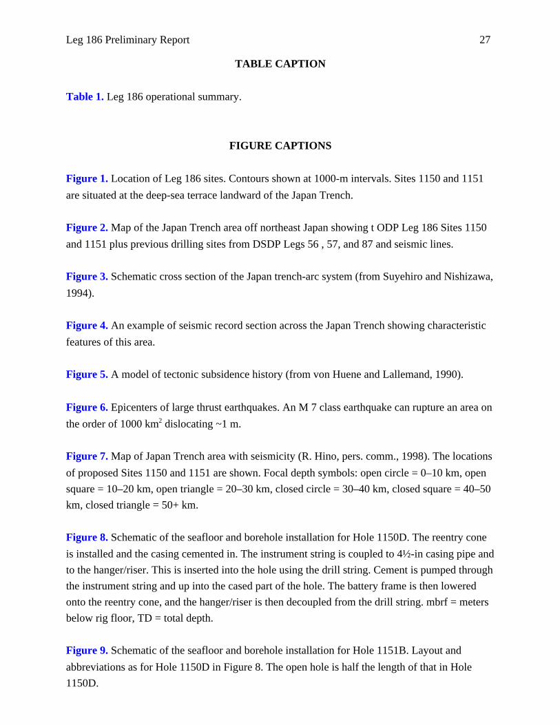
Figure 1. Location of Leg 186 sites. Contours shown at 1000-m intervals. Sites 1150 and 1151
are situated at the deep-sea terrace landward of the Japan Trench.
Figure 2. Map of the Japan Trench area off northeast Japan showing t ODP Leg 186 Sites 1150
and 1151 plus previous drilling sites from DSDP Legs 56 , 57, and 87 and seismic lines.
Figure 3. Schematic cross section of the Japan trench-arc system (from Suyehiro and Nishizawa,
1994).
Figure 4. An example of seismic record section across the Japan Trench showing characteristic
features of this area.
Figure 5. A model of tectonic subsidence history (from von Huene and Lallemand, 1990).
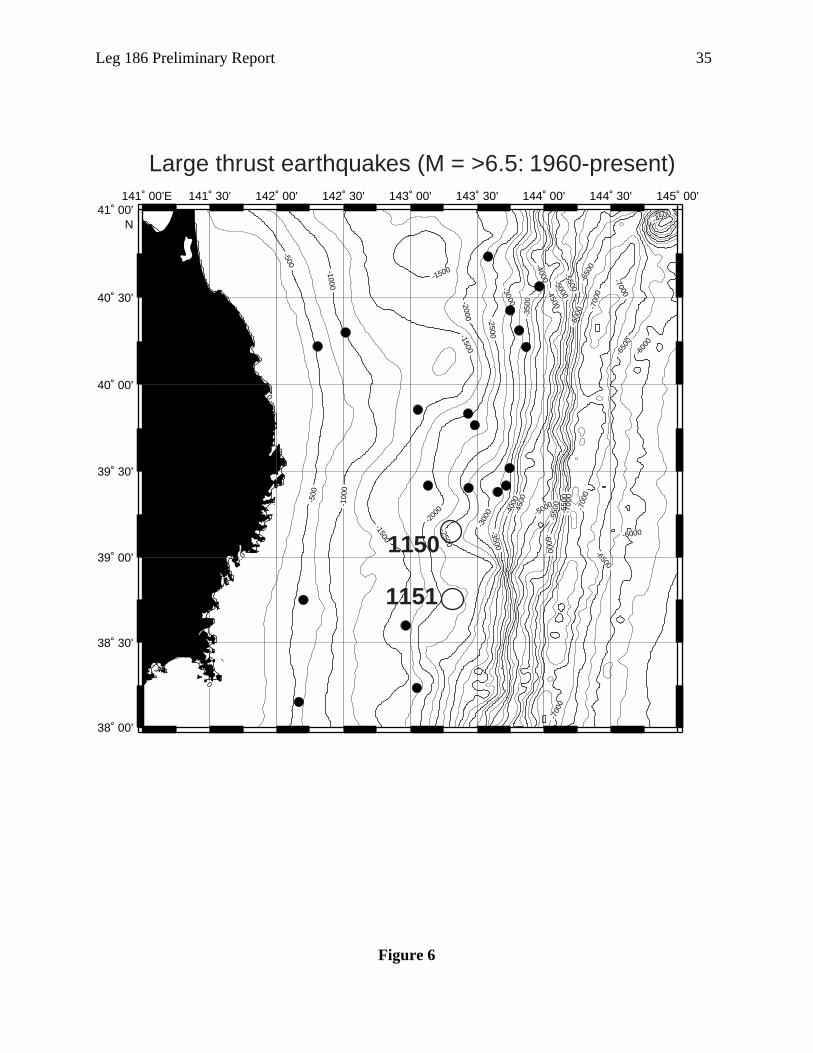
Figure 6. Epicenters of large thrust earthquakes. An M 7 class earthquake can rupture an area on
the order of 1000 km2 dislocating ~1 m.
Figure 7. Map of Japan Trench area with seismicity (R. Hino, pers. comm., 1998). The locations
of proposed Sites 1150 and 1151 are shown. Focal depth symbols: open circle = 0–10 km
square = 10–20 km, open triangle = 20–30 km, closed circle = 30–40 km, closed square =
km, closed triangle = 50+ km.
Figure 8. Schematic of the seafloor and borehole installation for Hole 1150D. The reentry c
is installed and the casing cemented in. The instrument string is coupled to 4½-in casing p
to the hanger/riser. This is inserted into the hole using the drill string. Cement is pumped th
the instrument string and up into the cased part of the hole. The battery frame is then lowe
onto the reentry cone, and the hanger/riser is then decoupled from the drill string. mbrf = m
below rig floor, TD = total depth.
Figure 9. Schematic of the seafloor and borehole installation for Hole 1151B. Layout and
abbreviations as for Hole 1150D in Figure 8. The open hole is half the length of that in Hol
1150D.

28 Leg 186 Preliminary Report
Figure 10. The principal aspects of the sensor installation. The cement is pumped through the
strainmeter and out the stinger extension, forming a solid base below and around the strainmeter
and other sensors.
Figure 11. Lithostratigraphic summary for Sites 1150 and 1151.
Figure 12. Chlorinity change in interstitial water. Data from this leg are compared with the ODP
Leg 126 Sea of Japan (Site 799) and DSDP Leg 57 Japan Trench (Site 438) results.
Figure 13. Age-depth curves for Leg 186 Sites and other Japan Trench sites. Geomagnetic
polarity time scale is also shown.
Figure 14. Smoothed curve presentation of sedimentation rates along the Japan Trench.
Figure 15. Ash records from Leg 186 compared with other Japan Trench sites.
Figure 16. Fault orientations. A. Hole 1150. B. Hole 1151.
Figure 17. Fault occurrence frequency at Sites 1150 and 1151.

Table
Interval MaximumRecovery drilled penentration
(%) (m) (m)
Hole 0 78.38 0.0 722.6Hole 9 56.32 703.3 1181.6Hole 0 0.00 1050.0 1050.0Hole 0 0.00 1139.8 1139.8Site 1 9 69.60 2893.1 1181.6
Hole 7 68.32 78.0 1113.6Hole 0 0.00 1113.0 1113.0Hole 5 104.68 0.0 97.2Hole 9 103.43 781.0 874.0Site 1 1 73.87 1972.0 1113.6
Leg 1 0 71.76 4865.1 1181.6
Total drill stringSeafloor length (mbrf)
depth (mbrf) (mbrf)
Hole 0 2692.2 3414.8Hole 0 2692.2 3873.8Hole 0 2692.2 3742.2Hole 0 2692.2 3832.0Site 1 0 2692.2 3715.7
Hole 8 2193.7 3307.3Hole 0 2193.7 3306.7Hole 0 2186.3 2283.5Hole 0 2184.0 3058.0Site 1 8 2189.4 2988.9
Leg 1 8 2440.8 3352.3Note:
1. Leg 186 operational summary.
Water Interval Coredepth Number cored recovered
ID Latitude Longitude (m) of cores (m) (m)
1150A 39°10.9148'N 143°19.9155'E 2680.8 7 6 722.6 566.41150B 39°10.9145'N 143°19.9470'E 2680.8 5 0 478.3 269.31150C 39°10.9172'N 143°19.8942'E 2680.7 0 0.0 0.01150D 39°10.9172'N 143°19.8942'E 2680.7 0 0.0 0.0150 Totals 39°10.9159'N 143°19.9127'E 2680.7 126 1200.9 835.7
1151A* 38°45.1195'N 143°20.0642'E 2182.2 108 1035.6 707.51151B 38°45.1244'N 143°20.0147'E 2181.6 0 0.0 0.01151C 38°45.0202'N 143°20.0425'E 2174.2 1 1 97.2 101.71151D 38°45.0138'N 143°20.0441'E 2171.9 1 0 93.0 96.1151 Totals 38°45.0695'N 143°20.0414'E 2177.5 129 1225.8 905.5
86 Totals 255 2426.7 1741.3
Arrival date Departure date Time on and time and time hole Number of Number of Number of
ID (local) (local) (hr) APC cores XCB cores RCB cores
1150A 6/22/99 18:30 26-Jun-99 99.75 1 2 6 41150B 6/26/99 22:15 3-Jul-99 159.25 0 0 51150C 7/23/99 15:30 23-Jul-99 7.00 0 01150D 7/23/99 22:30 28-Jul-99 116.50 0 0150 Totals 382.50 1 2 6 4 5
1151A* 7/28/99 22:00 2-Aug-99 115.75 0 0 101151B 8/2/99 17:45 9-Aug-99 168.00 0 01151C 8/9/99 17:45 10-Aug-99 16.00 1 1 01151D 8/10/99 9:45 12-Aug-99 61.75 1 0 0151 Totals 361.50 2 1 0 10
86 Totals 744.00 3 3 6 4 15 * = totals do not include a wash core (186-1151A-1W) collected at the top of Hole 1151A.
30 Leg 186 Preliminary Report
Figure 1
141°E142°
143°144°
145°146°
38°
39N
39°
40°
41°
42°N
1150
1151
Japa
n
1000
m
2000 m
3000 m
Eurasian Plate6000 m
Japan
Trench
Pacif
ic Plat
e
Leg 186 Preliminary Report 31
Figure 2
-650
0
-650
0
-600
0
-6000
-550
0
-550
0
-5500
-500
0-4
500
-400
0
-300
0
-2000-1500
-1500
-1000
-1000
-500
141˚E 142˚ 143˚ 144˚ 145˚ 146˚
38˚
39˚
40˚
41˚
42˚N
-250
0
1150
1151
436
438
584
JAPA
N T
RE
NC
H435441
434440
439
JNOC-2
JNOC-1ORI-3
32 Leg 186 Preliminary Report
Figure 3
NEOGENEPALEOGENEUPPER CRETACEOUS
Continentalshelf
Continentalslope Deep-sea terrace
Innertrench slope
Midslopeterrace Trench
Outertrenchslope
0
5
10
15
20
Accretion
142° Eat 39° 10' N
143° 144°
1150, 1151
6 km/s
7 km/s
Mantlewedge Se
ism
ogen
ic
Zone
Dep
th (
km)

Leg 186 Prelim
inary Report
33
Figure 4
PACIFIC PLATE
EW
Two-
way
trav
eltim
e
JAPANTRENCH
JT Sites

34L
eg 186 Preliminary R
eport
Figure 5
WHonsh
0
Ver
JAPAN TRENCH
0 km2
plifted
Presenttrenchaxis
Trenchaxis20 Ma
0
5
10 km
EReconstructedseafloor20 Ma
PointA
Seafloor20 Ma
e2
440441
434
DSDPSites
u I.
Paleogene
Neogene
Cretaceous
50 100 km
tical exaggeration = 5.4
Presentplateboundary
Plate boundary20 Ma
Area = 34beneath umargin
PresentseafloorDSDP Sites
438/439
Unconformity from subaerialerosion
Area of Subsidenc800 km
Leg 186 Preliminary Report 35
Figure 6
141˚ 00'E 141˚ 30' 142˚ 00' 142˚ 30' 143˚ 00' 143˚ 30' 144˚ 00' 144˚ 30' 145˚ 00'
38˚ 00'
38˚ 30'
39˚ 00'
39˚ 30'
40˚ 00'
40˚ 30'
41˚ 00'N
-700
0
-700
0
-700
0
-7000
-700
0
-650
0
-650
0
-650
0
-6500
-6000
-600
0
-6000
-600
0
-550
0
-5500
-5000
-5000
-450
0
-4500
-4500
-400
0
-4000
-3500
-350
0
-300
0
-3000
-2500
-2500
-200
0
-2000
-1500
-1500
-1500
-100
0
-1000
-500
-500
0
0
0
Large thrust earthquakes (M = >6.5: 1960-present)
1150
1151
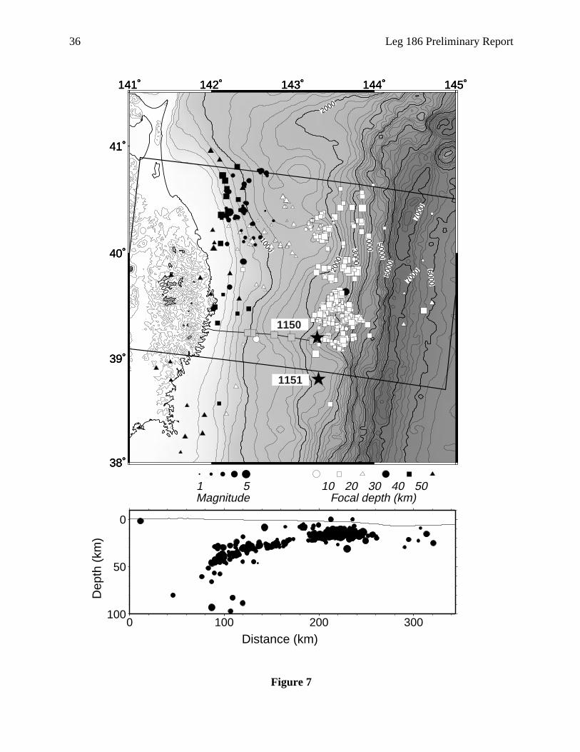
36 Leg 186 Preliminary Report
Figure 7
141˚ 142˚ 143˚ 144˚ 145˚
38˚
39˚
40˚
41˚
1000
2000
2000
3000
4000 5000
6000 600070
0070
00
141˚ 142˚ 143˚ 144˚ 145˚
38˚
39˚
40˚
41˚
1000
141˚ 142˚ 143˚ 144˚ 145˚
38˚
39˚
40˚
41˚
1 5Magnitude
10 20 30 40 50Focal depth (km)
0
50
100
Dep
th (
km)
0 100 200 300
Distance (km)
1150
1151
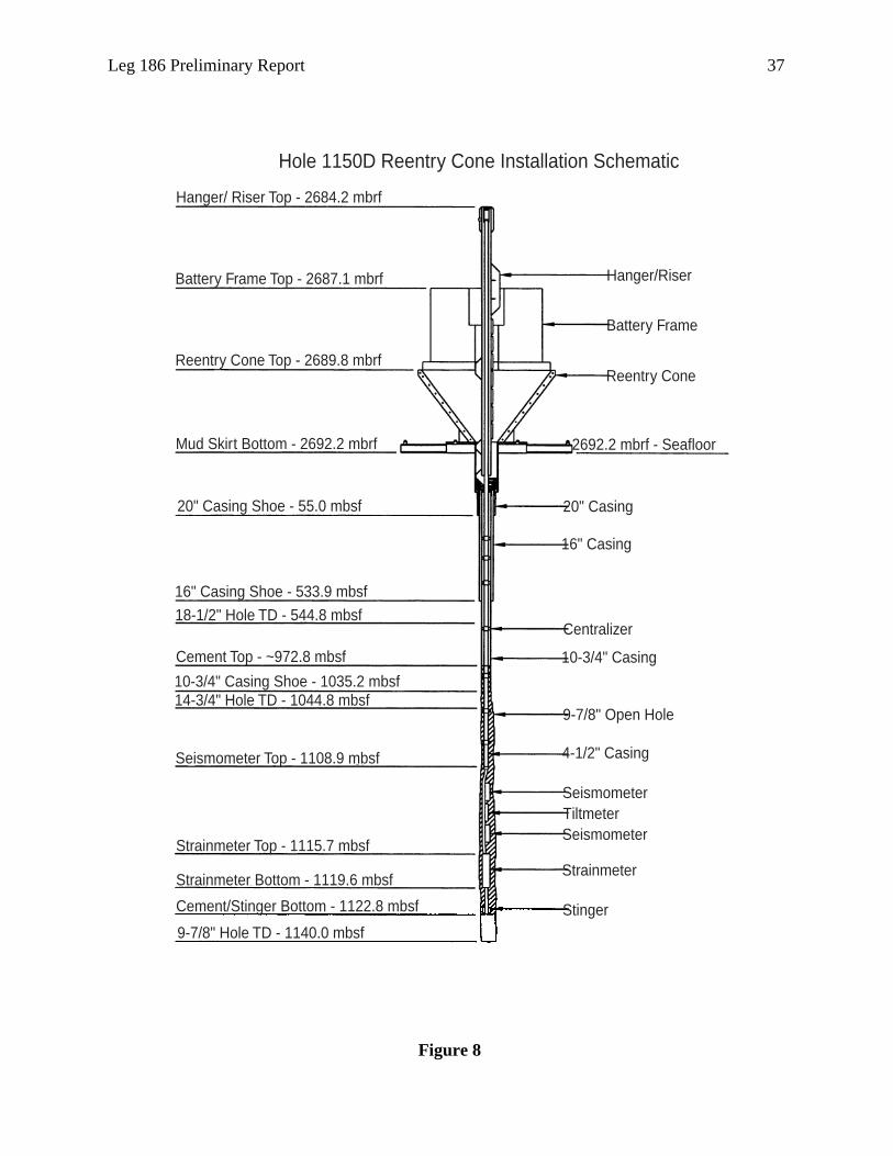
Leg 186 Preliminary Report 37
Figure 8
Hole 1150D Reentry Cone Installation Schematic
Hanger/ Riser Top - 2684.2 mbrf
Battery Frame Top - 2687.1 mbrf
Reentry Cone Top - 2689.8 mbrf
Mud Skirt Bottom - 2692.2 mbrf
20" Casing Shoe - 55.0 mbsf
16" Casing Shoe - 533.9 mbsf
18-1/2" Hole TD - 544.8 mbsf
Cement Top - ~972.8 mbsf
10-3/4" Casing Shoe - 1035.2 mbsf14-3/4" Hole TD - 1044.8 mbsf
Seismometer Top - 1108.9 mbsf
Strainmeter Top - 1115.7 mbsf
Strainmeter Bottom - 1119.6 mbsf
Cement/Stinger Bottom - 1122.8 mbsf
9-7/8" Hole TD - 1140.0 mbsf
Hanger/Riser
Battery Frame
Reentry Cone
2692.2 mbrf - Seafloor
20" Casing
16" Casing
Centralizer
10-3/4" Casing
9-7/8" Open Hole
4-1/2" Casing
SeismometerTiltmeterSeismometer
Strainmeter
Stinger
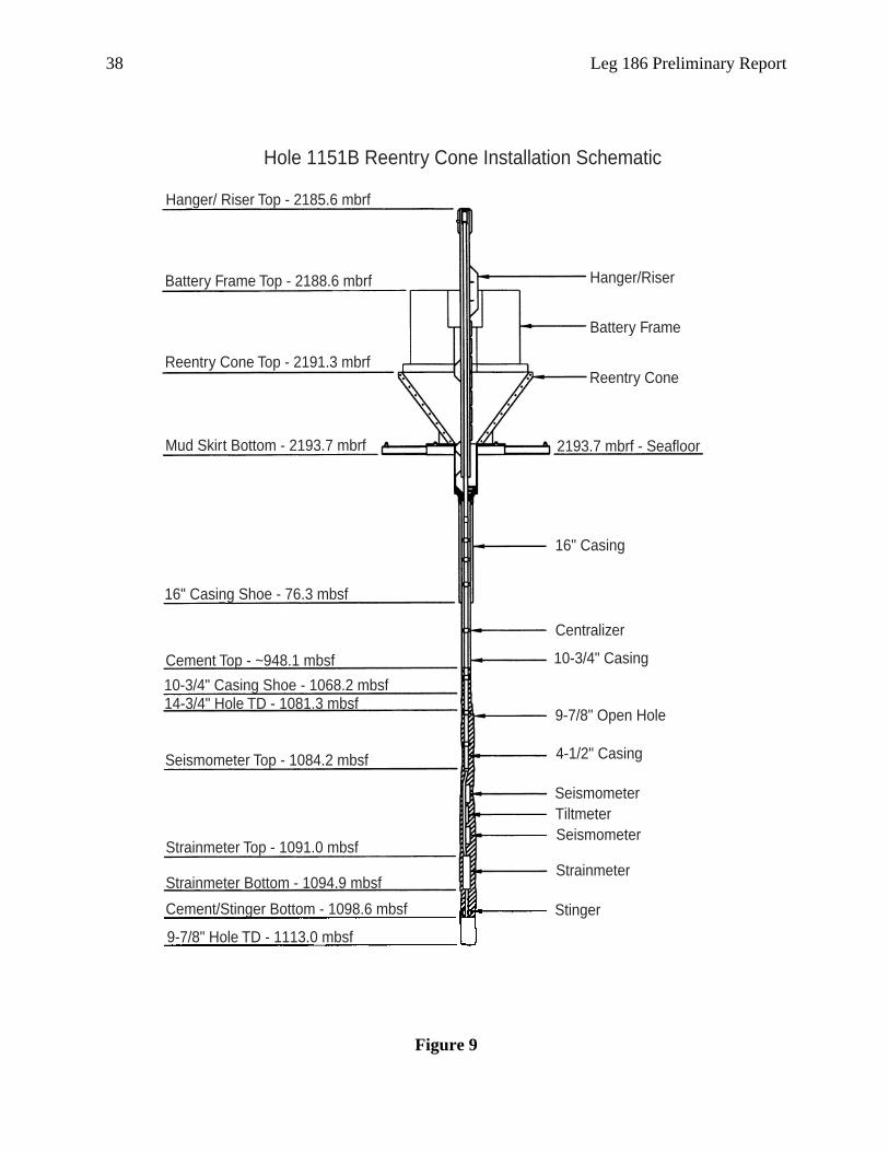
38 Leg 186 Preliminary Report
Figure 9
Hole 1151B Reentry Cone Installation Schematic
Hanger/ Riser Top - 2185.6 mbrf
Battery Frame Top - 2188.6 mbrf
Reentry Cone Top - 2191.3 mbrf
Mud Skirt Bottom - 2193.7 mbrf
16" Casing Shoe - 76.3 mbsf
Cement Top - ~948.1 mbsf
10-3/4" Casing Shoe - 1068.2 mbsf14-3/4" Hole TD - 1081.3 mbsf
Seismometer Top - 1084.2 mbsf
Strainmeter Top - 1091.0 mbsf
Strainmeter Bottom - 1094.9 mbsf
Cement/Stinger Bottom - 1098.6 mbsf
9-7/8" Hole TD - 1113.0 mbsf
Hanger/Riser
Battery Frame
Reentry Cone
2193.7 mbrf - Seafloor
16" Casing
Centralizer
10-3/4" Casing
9-7/8" Open Hole
4-1/2" Casing
SeismometerTiltmeterSeismometer
Strainmeter
Stinger
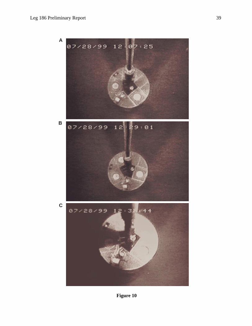
Leg 186 Preliminary Report 39
Figure 10
A
B
C
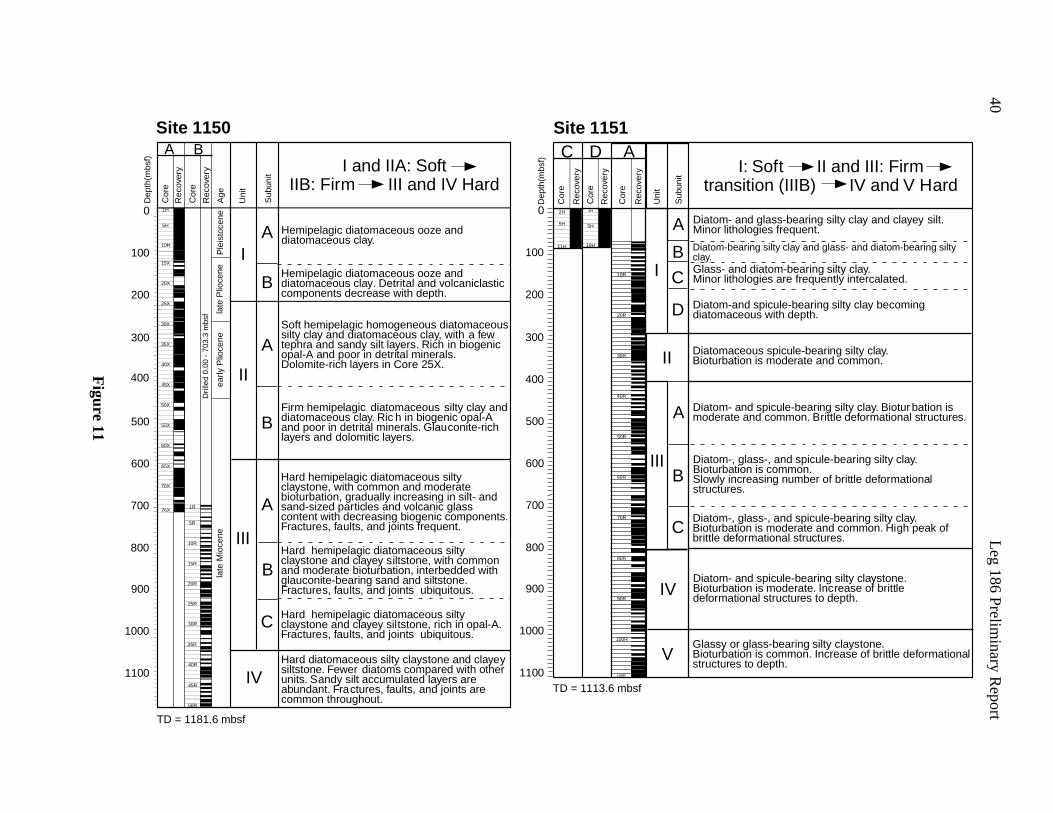
40L
eg 186 Preliminary R
eport
earing silty clay and glass- and diatom-bearing silty
nd diatom-bearing silty clay.hologies are frequently intercalated.
ceous spicule-bearing silty clay.tion is moderate and common.
and spicule-bearing silty clay. Biotur bation iste and common. Brittle deformational structures.
, glass-, and spicule-bearing silty clay.tion is common.
ncreasing number of brittle deformationales.
, glass-, and spicule-bearing silty clay.tion is moderate and common. High peak offormational structures.
and spicule-bearing silty claystone.tion is moderate. Increase of brittletional structures to depth.
r glass-bearing silty claystone.tion is common. Increase of brittle deformationals to depth.
and glass-bearing silty clay and clayey silt.hologies frequent.
and spicule-bearing silty clay becomingceous with depth.
I: Soft II and III: Firmsition (IIIB) IV and V Hard
Figure 11
TD = 1181.6 mbsf
early
Plio
cene
late
Plio
cene
late
Mio
cene
Ple
isto
cene
Sub
unit
Uni
t
Age
Rec
over
y
Rec
over
y
Cor
e
Cor
e
Dep
th(m
bsf)
Dril
led
0.00
- 7
03.3
mbs
f
Hemipelagic diatomaceous ooze anddiatomaceous clay.
Soft hemipelagic homogeneous diatomaceoussilty clay and diatomaceous clay, with a fewtephra and sandy silt layers. Rich in biogenicopal-A and poor in detrital minerals.Dolomite-rich layers in Core 25X.
Firm hemipelagic diatomaceous silty clay anddiatomaceous clay. Ric h in biogenic opal-Aand poor in detrital minerals. Glauconite-richlayers and dolomitic layers.
Hard hemipelagic diatomaceous siltyclaystone, with common and moderatebioturbation, gradually increasing in silt- andsand-sized particles and volcanic glasscontent with decreasing biogenic components.Fractures, faults, and joints frequent.
Hard hemipelagic diatomaceous siltyclaystone and clayey siltstone, with commonand moderate bioturbation, interbedded withglauconite-bearing sand and siltstone.Fractures, faults, and joints ubiquitous.
Hard diatomaceous silty claystone and clayeysiltstone. Fewer diatoms compared with otherunits. Sandy silt accumulated layers areabundant. Fractures, faults, and joints arecommon throughout.
Hemipelagic diatomaceous ooze anddiatomaceous clay. Detrital and volcaniclasticcomponents decrease with depth.
Hard hemipelagic diatomaceous siltyclaystone and clayey siltstone, rich in opal-A.Fractures, faults, and joints ubiquitous.
0
100
200
300
400
500
600
700
800
900
1000
1100
I
II
III
IV
A
B
A
B
A
B
C
65X
60X
50X
55X
45X
40X
35X
30X
25X
20X
15X
10H
5H
1H
1R
5R
10R
15R
20R
25R
30R
35R
40R
45R
50R
BI and IIA: Soft
IIB: Firm III and IV Hard
A
70X
76X
Site 1150
V
IV
C
II
A
B
I
0
100
200
300
400
500
600
700
800
900
1000
1100
10R
20R
30R
40R
50R
60R
70R
80R
90R
2H
5H
11H Diatom-bclay. Glass- aMinor lit
DiatomaBioturba
Diatom-modera
Diatom-BioturbaSlowly istructur
Diatom-Bioturbabrittle de
Diatom-Bioturbadeforma
Glassy oBioturbastructure
Diatom-Minor litA
III
B
C
D
100R
C D
Rec
over
y
Rec
over
y
Cor
e
Cor
e
Cor
e
Rec
over
y
Dep
th(m
bsf)
10H
5H
1H
TD = 1113.6 mbsfS
ubun
it
Uni
t
A
109R
Diatom-diatoma
tran
Site 1151
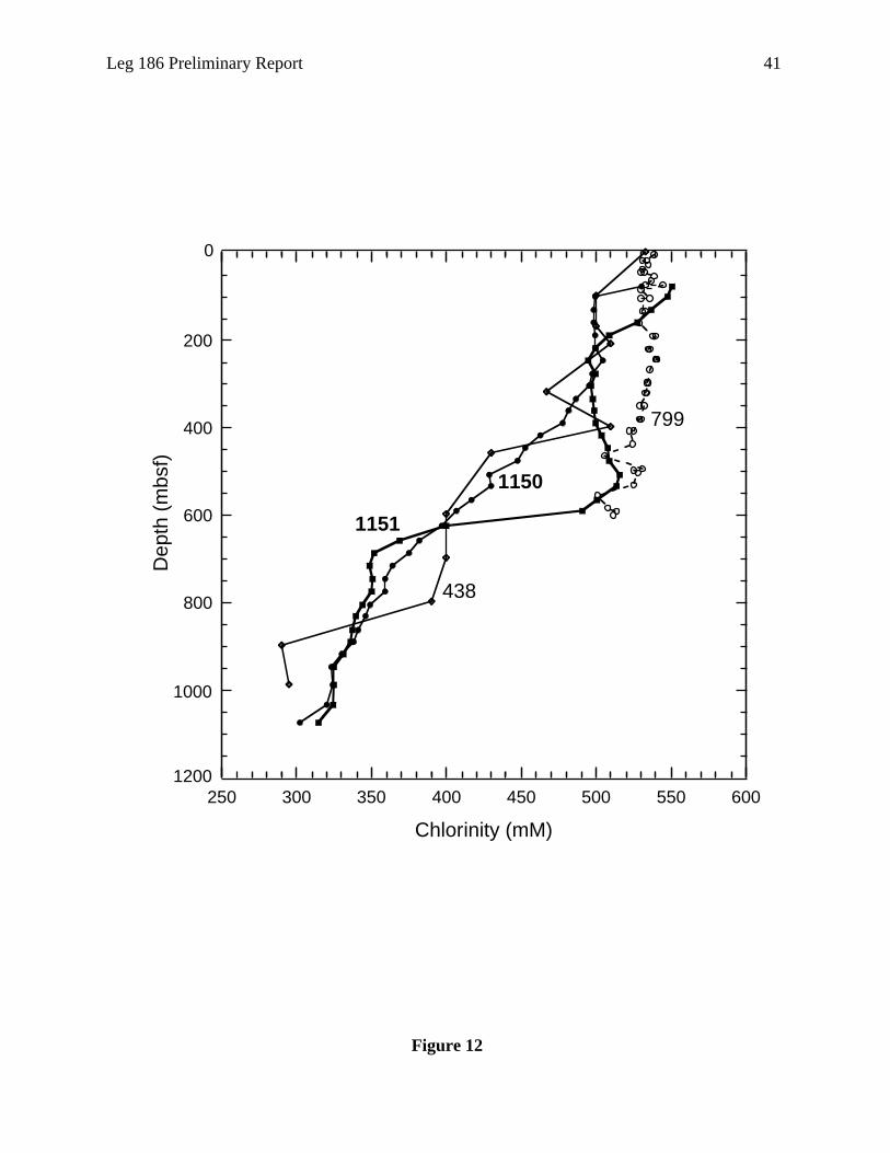
Leg 186 Preliminary Report 41
Figure 12
250 300 350 400 450 500 550 600
0
200
400
600
800
1000
1200
Chlorinity (mM)
Dep
th (
mbs
f)
438
1150
1151
799

42 Leg 186 Preliminary Report
Figure 13
Site 1151
Site 1150
Diatom datums fromHoles 1151C and D
Site 438
Site 584
Age (Ma)D
epth
(m
bsf)
Pleistocene PlioceneLate Early
MioceneLate Middle
C1 C2 C2A C3 C3A C3B C4 C4An r n r n r n r n r n r n r n r n r
C5
0 2 4 6 8 10 12 14 16
0
200
400
600
800
1000
1200
n rC5AA B C D
C5B C5Cn r n
3 45 6
7
8
9
1011
12
1314
1516
1718
1920 21
2223
1
45
2
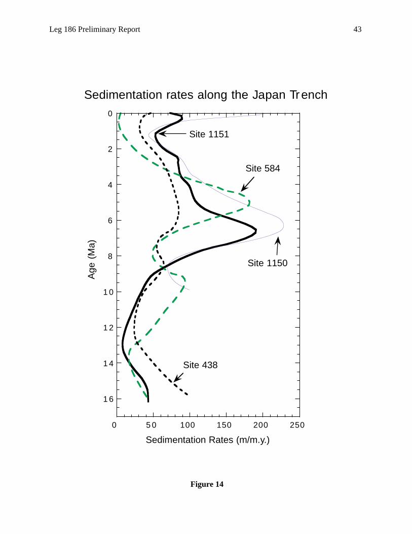
Leg 186 Preliminary Report 43
Figure 14
0 5 0 100 150 200 250
0
2
4
6
8
1 0
1 2
1 4
1 6
Sedimentation rates along the Japan TrenchA
ge (
Ma)
Site 584
Site 1150
Site 1151
Site 438
Sedimentation Rates (m/m.y.)

44 Leg 186 Preliminary Report
Figure 15
0.2
0.4
0.6
0.8
1.0
1.2
1.4
ODP Leg 186
Site 1150
Site 1151
Ash
laye
rs +
pat
ches
/m
0.0
10.0
20.0
30.0
40.0
50.0
0 1 2 3 4 5 6 7 8 9 1 0 1 1 1 2 1 3 1 4 1 5 1 6
DSDP Legs 56 and 57
Site 438
Hole 438A
Site 440
Age(Ma)
Ash
laye
rs/m
.y.
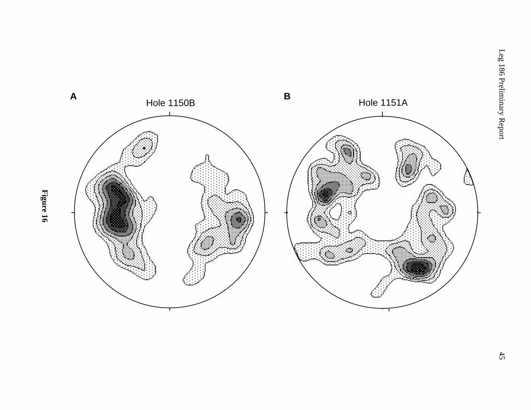
Leg 186 Prelim
inary Report
45
Figure 16
Hole 1151A
Hole 1150BA B
46 Leg 186 Preliminary Report
Figure 17
0
1
2
3
4
5
6
7
8
9
10
400 500 600 700 800 900 1000 1100 1200
Faults 1150B
Faults 1151A
Faults and Strike Slip Faults of Sites 1150 and 1151
Depth (mbsf)
Strike slip faults1151A
Num
ber
per
met
er

Leg 186 Preliminary Report 47
and
arine
e by
he
mber
ly
ing in
he
e
on 22
d
eacon
at this
at
ara
e APC
ore
t that
gas
OPERATIONS SYNOPSIS
Port Call
Leg 185 ended and Leg 186 officially began with the first line ashore at 2018 hr on Monday
14 June 1999 in Yokohama, Japan (all times are reported are in local ship time, which is UTC +
9 hr). Because of the large amount of casing to be used during Leg 186, the riser (casing) hold
had to be emptied and rearranged. The following casing was loaded: eight joints of 20-in (94
lb/ft; ~13.86 m/joint; total length = ~111 m), 83 joints of 16-in (75 lb/ft; ~12.70 m/joint; total
length = ~1054 m), 156 joints of 10¾-in (40.5 lb/ft; ~12.98 m/joint; total length = ~2024 m),
179 joints of 4½-in (10.5 lb/ft; ~11.64 m/joint; total length = ~2084 m) casing.
Port call activities included a number of tours, which were managed by the Japanese M
Science and Technology Center (JAMSTEC), and a reception hosted the evening of 16 Jun
the Ocean Research Institute (ORI). All Ocean Drilling Program/Texas A&M University
(ODP/TAMU) and Sedco employees plus scientists from Legs 185 and 186 were invited. T
reception was attended by many dignitaries including consulate personnel from various me
countries and many Japanese scientists involved with the future of ocean drilling, particular
through the OD21 initiative. In the end, port call extended a day longer than anticipated ow
part to a strike by the Yokohama dock workers that fortunately only extended through the
weekend. The extra time during the weekend was used to assemble the battery packs for t
borehole instruments and to replace the aft crane boom on the port side of the ship.
Transit to Site 1150
The JOIDES Resolution departed Yokohama at 1145 hr on Monday 21 June. Traveling th
363-nmi transit at an average speed of 11.9 kt, we arrived at Site 1150 (JT-1C) at 1830 hr
June and began drilling operations. The initial beacon deployed was released and recovere
because it was not as close to the desired site location as we would have liked. A second b
was released at 2047 hr and, because we would be spending a significant number of days
site, a back-up beacon was deployed at 2145 hr.
Hole 1150A
Hole 1150A was spudded at 0530 hr on 23 June using the advanced hydraulic piston
corer/extended core barrel (APC/XCB) coring system in a water depth of 2680.8 m (2692.2
mbrf). Cores 3H through 12H were oriented using the Tensor tool. Three successful Adara
temperature measurements were taken on Cores 3H at 26.7 mbsf, 6H at 55.2 mbsf, and 9H
83.7 mbsf. An overpull of 60,000 lb after the third Adara run led us to cancel any further Ad
measurements.
Biogenic methane was present throughout the APC-cored interval, which led us to ceas
coring. The gas content coupled with the tendency of the APC to pack material fully in the c
liners resulted in the explosive ruptures of the core liners for Cores 10H and 11H. It was fel
rotary type coring would alleviate some of the propensity of the liners to explode even if the
48 Leg 186 Preliminary Report
8 m
r, there
ving
sfully
r Core
ara
of
hane
ane and
d
e
r 20
erage
18.25
,
ulled
future
2.5 hr
bsf,
ut
afloor.
A and
total
ne with
own
ered
an
remained present in the cores. APC coring was therefore terminated before reaching any typical
refusal point. Overpull at that point was running a mere 15,000–20,000 lb for non-Adara
deployments.
XCB coring began with Core 13X and continued through Core 76X to a depth of 3414.
(722.6 mbsf). Methane gas continued to be present in the cores at the same level; howeve
was only a single exploding core liner incident with the XCB and this occurred before remo
the liner from the core barrel. The Davis-Villinger Temperature Probe (DVTP) was succes
run twice during the XCB-cored interval: once after Core 13X at 116.4 mbsf and again afte
18X at 164.4 mbsf. The three Adara data points, two DVTP data points, and the single Ad
mudline temperature measurement combined to define a very linear temperature gradient
33.9EC/km. There were no hydrocarbon safety issues while drilling this hole. Biogenic met
was present for the entire section cored with head space data averaging around 3% meth
1–2 ppm ethane.
Hole 1150A was cored to a total depth of 722.6 mbsf. The maximum drill string deploye
was 3414.8 mbrf. A total of 566.40 m of core was recovered for an average of 78.4% of th
section cored. Penetration rates varied from 99 m/hr in the surface sediments to just unde
m/hr at total hole depth (TD). The entire XCB cored section of 610.4 m was cored at an av
rate of penetration (ROP) of 35.1 m/hr. Of the 112.2 m penetration with the APC system, 1
m of core was recovered (105.4% recovery), and, of the 610.4 m penetrated with the XCB
448.15 m (73.4%) of core was recovered (Table 1). The APC/XCB drilling assembly was p
clear of the mudline at 1415 hr on Saturday 26 June 1999.
Jet-In Test
The ship was offset ~20 m west of Hole 1150A and a jet-in test was conducted for the
emplacement of the reentry cone and 20-in casing string. The jet-in test was completed in
after washing without rotation to a depth of 67.0 mbsf. A hard layer was detected at 56.0 m
though increased weight on the bit (WOB) and circulation kept the drill bit advancing witho
any problem. The jet-in test was concluded at 1830 hr 26 June when the bit cleared the se
Hole 1150B
The APC/XCB core bit reached the rig floor at 2215 hr 26 June 1999 ending Hole 1150
beginning Hole 1150B. The bit was found to be in excellent condition after accumulating a
of 23.2 rotating hr and 913.8 m of penetration.
Hole 1150B was spudded about 44 m east of Hole 1150A at 0415 hr on Sunday 27 Ju
the RCB coring system in a water depth of 2680.8 m (2692.2 mbrf). The hole was drilled d
to 703.3 mbsf before coring began. Drilling was briefly halted during this interval when a
hydraulic line in the top drive umbilical ruptured. Extremely heavy rain and high wind hamp
the repair effort, which took 1.5 hr. Overall, drilling and connection time was 19.75 hr, with
average ROP of 35.6 m/hr.

Leg 186 Preliminary Report 49
ole
anner
g 14
ill
as
d
nant
est
0 hr
ne
he
RCB coring was initiated about two cores above the XCB termination depth of 722.6 mbsf.
We had originally planned to core to 1000 mbsf but continued deeper in search of more indurated
sedimentary rock, which would be better suited for the borehole instruments planned for
installation in Hole 1150C. In addition, we wanted to get deep enough to log through the rock
units directly below and at the depth at which the borehole instruments were to reside. Coring
ceased at 1181.6 mbsf on 1 July, when it was deemed that the lithification and depth was
sufficient to accomplish our goals. In all, we cored 478.3 m and recovered 269.4 m of sediment
and sedimentary rock from 50 RCB cores, for an average recovery of 56.3% (Table 1).
No hydrocarbon problems were experienced in this hole. Methane gas continued to be
present in the cores at an average of about 3%, slightly higher than the average of 1.5% seen in
Hole 1150A. Ethane was present at ~10 ppm, and no higher hydrocarbons were identified.
In preparation for logging, we completed a wiper trip, circulated a 30-bbl sepiolite pill,
released the bit, displaced the hole with 330 bbl of sepiolite logging mud, and pulled the bottom
of the drill pipe up to ~114 mbsf. Though we encountered no apparent restrictions during the
wiper trip, the first logging run encountered a tight interval at ~643 mbsf, which we were unable
to get through. Logging with the triple combo tool string proceeded upward from 646 mbsf. The
second logging run, using the Formation MicroScanner (FMS) tool string, encountered a second
obstruction, this time at ~473 mbsf, and the hole was logged upward from this depth. After
completing the first two logging runs, we lowered the drill string to 742 mbsf. No resistance was
identified by the driller. This allowed three logging runs—the triple combo, FMS, and boreh
televiewer runs—to reach to within 7 to 11 m of the bottom of the hole. Formation MicroSc
data indicated an elliptical hole with one axis diameter measuring 10 in, the other measurin
in.
The wireline logging tools and sheaves were rigged down by 0600 hr 3 July, and the dr
string was pulled to a depth of ~3292 m (~600 mbsf). A 30-bbl cement plug (~96 m long) w
set at that point to ensure that there would be no communication of seawater downhole an
through a fracture network to the reentry installation. The drill string was pulled clear of the
seafloor at 0900 hr 3 July, and the drill string was flushed with seawater to remove any rem
cement.
Hole 1150C
While recovering the drill string the drillship was offset ~80 m west, which was ~40 m w
of the original APC/XCB Hole 1150A. The end of the drill string reached the rig floor at 133
on 3 July 1999, ending Hole 1150B and beginning Hole 1150C.
Reentry Cone and 20-in Casing String Installation
The upper guide horn was removed to assemble the 20-in casing string and reentry co
ensemble. Assembly of the 20-in casing went exceptionally well, taking only 2.5 hr to join t
shoe joint, three additional joints of casing, and the Dril-Quip running tool.

50 Leg 186 Preliminary Report
With the reentry cone positioned beneath the rotary table on the moonpool doors, we
attempted to lower and latch the 20-in casing hanger into the reentry cone. The first sign of
trouble occurred when the hanger landed at the base of the reentry cone panels rather than
proceeding smoothly into the bore of the transition pipe. Even after jostling the cone around the
hanger, the hanger continued to hang up sporadically in the transition pipe and would not move
freely down to the landing shoulder. We decided that there must be a significant interference
between the 20-in casing hanger body and the weld attaching the latch ring body extension. To
save time, the top joint of 20-in casing was laid out with the hanger attached. The next joint of
20-in casing was also laid out. The third and fourth joints of casing plus casing shoe were raised
up into the derrick, allowing access to the reentry cone. The cone was then repositioned onto its
side to allow a more detailed inspection. After inspecting the transition areas of both reentry
cones aboard it was apparent that the axial weld on the transition pipe and the weld attaching the
transition pipe to the latch ring body extension protruded far enough to prevent the casing hanger
from traveling freely to the landing shoulder. Also, it appears from field measurements that the
uppermost ~1-in of the latch ring body extension was incorrectly machined. Once the welds and
the incorrectly machined portion of the latch ring were ground flush on the inside diameter, the
casing string was once again assembled, and this time the casing hanger latched into the proper
position as designed. This incident resulted in 8.5 hr of lost time.
The casing string and reentry cone were lowered to a depth of 2654 m, and the subsea camera
on the vibration-isolated televison (VIT) frame (referred to as VIT camera herein) was deployed
during the pipe trip. Hole 1150D was spudded at 0930 hr on 4 July by jetting the casing into the
seafloor. It took 4.25 hr to jet-in the casing to a depth of 58.13 mbsf and land the reentry cone at
the seafloor at a depth of 2692.2 m.
The pipe was tripped back to the rig floor, where the nozzles on the bit were replaced and the
bottom-hole assembly (BHA) was assembled in preparation for drilling the 18.5-in diameter
hole. The first reentry into the cone was made at 0245 hr on 5 July. By 0145 hr on 6 July we had
drilled the 18.5-in hole down to a depth of 539.8 mbsf, for an average drilling rate of 27.5 m/hr.
The hole was swept clean with two 50-bbl sepiolite pills and a wiper trip, displaced with 550 bbl
of sepiolite, and the drill string pulled out of the hole, reaching the rig floor at 1245 hr.
Supply Boat Rendezvous
The 30-m-long sea-going tug Fumi Maru #26 came alongside to discharge cargo and seven
passengers at 0600 hr on 6 July. Arriving personnel included Masanao Shinohara from the
Earthquake Research Institute at Tokyo University (shipboard participant), Kevin Sharp (cable-
connector technician from Ocean Design), Andrew Green and Murry McGowan (seismometer
technicians from Guralp Systems Ltd., United Kingdom), and Michael Acierno (computer
specialist from Carnegie Institution). In addition, a two-man film crew (Satoru Ninomiya and
Daisuke Yamada), hired by ORI, came aboard. The film crew and the two Guralp technicians
departed the ship the following day at 1200 hr after their work was completed.

Leg 186 Preliminary Report 51
845
ent,
The
nd
e
The
d at
ion
p to
ly. The
a
mbly.
g had
sh (the
tool
he
ll
ges
pipe.
a 5-
h
empts
asing.
5-in
The 16-in Casing String
The rig crew ran the 42 joints (525.87 m) of 16-in casing, assembled the casing hanger, and
engaged the Dril-Quip running tool in only 5.5 hr. The 16-in casing string was lowered to the
seafloor, and the second reentry occurred at 0130 hr on 7 July. The casing began to show
resistance almost immediately upon entry into the 20-in conductor pipe. The circulating head had
to be installed and the casing circulated down to 137.8 mbsf. While running the casing into the
bore hole, weights of 20–30 kilopounds (kips) were used to advance the casing string. By 0
hr on 7 July, the casing hanger was landed. The casing was cemented using 30 bbl of cem
which should have resulted in cement reaching ~100 m up the exterior of the 16-in casing.
cementing dart was launched and at 1015 hr the plug was landed at the cementing shoe a
confirmed with 500 psi pump pressure. Within 15 min, the running tool was released and th
drill string was then flushed with seawater to remove any residual cement in the drill string.
pipe was pulled out of the hole clearing the rotary table at 1600 hr that same day.
After attaching a new 14¾-in drill bit, the drill string was lowered and the cone reentere
2315 hr on 7 July. Because the bit was hanging up and not sliding smoothly into the transit
pipe, the bit was pulled clear of the reentry cone at 2345 hr and the top drive was picked u
allow the pipe to be rotated. The reentry cone was reentered once again at 0030 hr on 8 Ju
bit was “rolled” gently into the transition area. The 16-in cementing shoe was contacted at
depth of 527 mbsf and we began drilling out the cementing shoe, wiper plug, and dart asse
Drilling had been in progress for 2.5 hr when at 0640 hr, 60,000 lb of string weight was
suddenly lost along with 300 psi of pump pressure. Calculations indicated that the drill strin
parted at or near the seafloor. The VIT camera was deployed to verify the position of the fi
part of the drill string in the hole) in relation to the reentry cone. The top of the fish was not
visible. The camera showed, however, that the 5-in drill pipe had parted about 1 m below a
joint in the area where the tube of the pipe had been rubbing the casing hanger during the
cement-shoe drilling operation. Once the drill string was at the surface it was verified that t
string did part in the 5-in drill pipe, 0.98 m below a box tool joint. The pipe showed signs of
rubbing against the hanger or the transition pipe of the reentry cone during rotation, but sti
measured a full 5-in in diameter. The pipe coating was worn away, but no deep cuts or gou
were noted. The failure was a clean break with no metal extending over the diameter of the
To retrieve the fish, we used fishing tools consisting of a 8-7/8-in diameter overshot with
in basket grapple and an 8-7/8-in diameter wall hook guide. The fish consisted of the BHA
assembly plus 13-2/3 stands of 5-in drill pipe for a total length of 526.5 m. The top of the fis
was calculated to be at 2693.3 m, which put it near the top of the 16-in casing hanger. The
fishing assembly was made up and run into the top of the reentry cone. On the first two att
to engage the fish, the overshot slid down beside the fish in the 15-1/8-in inside diameter c
On the third attempt the guide passed over the top of the fish and the grapple engaged the
drill pipe tube. The fish was pulled to the surface and the broken joint removed.

52 Leg 186 Preliminary Report
er,
0C was
entry
drive
asing
of the
s
ansition
ecause
to
limit
erse
n was
etting,
-up
casing
l
in
he
able
nts of
plug it
ints
At 1045 hr on 8 July Hole 1150C was reentered. As on the previous reentry, the bit once
again hung on the lip of the reentry cone at the entrance to the transition pipe. This time, chain
tongs were used to rotate the pipe and it eventually slipped into the throat of the reentry cone.
The pipe was run to bottom and at 1245 hr we once again began drilling operations. At 1400 hr
on 10 July, we finished drilling the 14.75-in hole for emplacement of the 10.75-in casing string.
It took 24.25 hr to drill the 510 m of 14.75-in hole down to a depth of 1050.0 mbsf, an average
rate of 21 m/hr. Sepiolite mud sweeps of 30 bbl every 40 m were pumped during the drilling
process and the hole was circulated with a 50-bbl sepiolite pill. The pipe was tripped to the rig
floor at 0245 hr on 11 July.
The 10¾-in Casing String
The 10¾-in casing string, consisting of 82 joints of 10¾-in casing plus the casing hang
was assembled just 8.75 hr. The casing string was lowered to the seafloor, and Hole 115
reentered Hole 1150C at 1735 hr on 11 July.
An hour was spent attempting to advance the casing shoe through the throat of the re
cone without success. The bit was pulled clear of the reentry cone at 1630 hr and the top
was picked up. The cone was reentered after 35 min of ship maneuvering but the problem
persisted. As the casing string was lowered, the casing shoe would catch and cause the c
string to bend or bow with as little as 5000–8000 lb of weight. We observed the deflection
casing string with the subsea camera, which moved off center of the hole when weight wa
applied to the shoe. On previous reentries the same problem had occurred entering the tr
pipe/casing hanger area but had been solved with rotation that allowed the bits to pass. B
the Dril-Quip running tool released with right-hand rotation, left-hand rotation was planned
work the casing shoe through the transition pipe/casing hanger area. The top drive torque
was set at 150 A (~2000 ft-lb) to prevent overtorquing the running tool and to keep the rev
torque well below the make-up torque of the casing (4200 ft-lb). Very slow reverse rotatio
initiated, and the pipe was worked in an attempt to pass. Because of the low torque limit s
rotation stopped as soon as the casing shoe took weight and never approached the make
torque of the casing. Rotation at the reentry cone matched the rotation at the surface. The
string was worked with and without rotation with weights reaching 12,000 lb during vesse
heaves. The vessel was also offset 20 m forward at this time to try to reposition the casing
relation to the cone.
At 1750 hr on 11 July the string parted in a casing coupling 17 joints (~205 m) above t
casing shoe. Part of the casing was observed falling down through the previously impass
transition pipe and into the hole. The VIT camera was recovered and the remaining 67 joi
casing were pulled to the rig floor. Several days later when we returned to Hole 1150C to
with cement, we observed many of the lost joints lying on the seafloor. Thus, only a few jo
may have fallen into the hole.
Leg 186 Preliminary Report 53
om.
ssel
to the
rage
After reviewing the operation, the failure of the casing coupling was attributed to the flexing
and bending of the casing string. This may have been caused by flaws in the reentry cone. As
noted earlier in the leg, when trying to land the 20-in casing hanger in the reentry base used on
Hole 1150C, the landing ring body extension welded to the transition pipe was observed to be
machined improperly and the welds inside the pipe were not dressed to specifications. When the
same machined area on the reentry cone for Hole 1150D was ground flush, it was noticed that the
body extension was not welded properly, creating a serious weakness to the structure. If the same
welding techniques were used on the base of the reentry cone for Hole 1150C, the weld could
have failed, creating an opening between the casing hangers and the transition pipe welded to the
bottom of the base. This could have been the cause of the difficulties getting the bits and casing
shoes to pass through the transition pipe/hanger area. This also could have been the problem that
led to the drill pipe failure that occurred while drilling out the 16-in casing shoe.
Considering the rapid rate at which the casing string dropped into the hole, there would have
been a slim chance of removing the pile of metal that would have crashed at the base of the hole.
There was also concern that even if we were able to fish the casing, we might not have been able
to pull it through the flawed reentry cone. Thus, we abandoned operations on Hole 1150C and
started over in Hole 1150D.
Hole 1150D
Operations at Hole 1150D began with a great deal of welding and grinding to bring the
reentry cone up to required tolerance and strength specifications. A total of 14 hr were required
before the reentry cone could be positioned in the center of the moonpool doors. In the
meantime, the ship was offset 60 m south of Hole 1050A.
Reentry Cone and 20-in Casing String Installation
Four joints of 20-in casing (including the shoe joint) were assembled and attached to the 20-
in casing hanger. The hanger was lowered into the reentry cone and engaged the reentry cone as
designed without incident. Hole 1150D was spudded at 0545 hr on 13 July at a seafloor depth of
2692.2 m. The cone landed at the seafloor 11 hr later positioning the 20-in casing shoe at a depth
of 55.0 mbsf.
The drill string was pulled back to the ship and we changed out the No. 16 jets with No. 24
jets in the 18½-in drill bit. The BHA was assembled and the drill string was run back to bott
The first reentry was made into Hole 1150D at 0345 hr on 14 July after maneuvering the ve
for 45 min. This time the bit slid smoothly into the throat of the reentry cone and continued
casing shoe without any resistance. We drilled the hole to a depth of 544.8 mbsf at an ave
penetration rate of 35.7 m/hr. Following bentonite mud sweeps, a wiper trip, and a hole
displacement with sepiolite mud, we tripped the drill string to the rig floor.

54 Leg 186 Preliminary Report
d at
al
with
and
830 hr
the
lated
shoe.
g was
ip for
le
hout
/gal
r
dditional
s
130 hr
kt. The
hr on
went
le to
d
rd
nts of
p
The 16-in Casing String
By 1230 hr on 15 July, the drill crew had assembled 41 joints of 16-in casing. Reentry was
made at 1700 hr on 15 July without requiring any time to reposition the vessel. The 16-in casing
shoe went through the reentry cone transition without any problem and the string was advanced
to a depth of 278 m before the top drive was picked up. The remaining portion of the casing
string was “washed” to bottom in the relatively tight hole. The 16-in casing shoe was lande
533.9 mbsf at 0100 hr on 16 July and cemented into place with 30 bbl of cement 15.8 lb/g
(~1.92 g/cm3). The drill string was recovered to the rig floor by 0745 hr on 16 July.
After positioning the ship for 30 min, Hole 1150D was reentered at 1315 hr on 16 July
the 14¾-in drill bit. As before, the bit went straight through the reentry cone transition area
advanced to bottom where the cementing shoe was tagged at a depth of 532.8 mbsf. By 0
on 17 July, the hole was drilled to a depth of 1044.8 mbsf. Only 16 hr was required to drill
500 m of hole at an average rate of penetration of 31.3 m/hr. As before, the hole was circu
with a 50-bbl bentonite mud sweep, and a wiper trip was conducted up to the 16-in casing
The 10¾-in Casing String
It took ~7.5 hr to assemble 80 joints of 10¾-in and the casing hanger. The casing strin
lowered, the VIT camera was deployed, and at 0800 hr on 18 July, after positioning the sh
30 min, Hole 1150D was reentered for the fourth time. Unlike the difficulties we had at Ho
1150C, this time the 10¾-in casing shoe slipped through the throat of the reentry cone wit
resistance and the string was run to 1044.8 mbsf and then cemented with 50 bbl of 15.8 lb
cement.
During this operation, we had been monitoring a storm system that was heading in ou
direction. To avoid the possibility of being caught in a storm while deploying the borehole
instruments, we decided to delay the deployment and instead head to Yokohama to get a
casing and a reentry cone, which were needed for Site 1151 operations. The drill pipe wa
tripped to the surface, the rig floor was secured for transit, and the ship got under way at 2
on 18 July.
Yokohama Port Call for Resupply
The 370-nmi distance to Yokohama was covered in 36.8 hr at an average rate of 10.3
pilot came aboard at 0750 hr and we proceeded dockside with the first line ashore at 1000
20 July. Even though it was a Japanese holiday called “Day of the Oceans,” the resupply
exceptionally well. The shipping agent, Kiyoaki Chiba of Sea Trade & Agency Inc., was ab
arrange for a forklift and foreman to remain on duty to assist the ship’s crew with continue
loading activities after normal holiday working hours had ended. In addition, loading was
expedited by having the cargo predelivered dockside before our arrival. Cargo taken aboa
included one reentry cone, six joints of 16-in casing, 48 joints of 10¾-in casing, and 32 joi
4½-in casing. In addition, Michael Acierno (Carnegie computer specialist) and Kevin Shar

Leg 186 Preliminary Report 55
e
n
re was
e
on
cone
ts
ith
entry
or
epth of
vent
d. At
try
(Ocean Design connector technician) both departed the vessel since their work was completed.
Dan Malone, Overseas Drilling Ltd. warehouseman replacement for the retiring Mick Malone
(on the other crew), came aboard to spend the rest of the leg coordinating with Mike Cole, the
warehouseman on the Leg 186 crew. All loading was completed by 1800 hr, although we were
unable to depart right away because of harbor congestion associated with the holiday fireworks
display. The delayed provided a chance for all on the JOIDES Resolution to enjoy nearly 2 hr of
fireworks and some much-needed entertainment along the dock. We eventually secured both
pilots required for transit out of the port area and departed at 2145 hr on 20 July.
Return to Hole 1150D
The 364-nmi transit back to Site 1150 took 31 hr at an average rate of 11.7 kt. We acquired
the positioning beacon at 0700 hr the morning of 22 July.
In exceptionally calm seas, we reentered Hole 1150D. Using a 9-7/8-in tricone drill bit, we
drilled through the cementing shoe at a depth of 1031.8 mbsf and began drilling the 9-7/8-in
diameter hole. Drilling in Hole 1150D was completed to a depth of 1140.0 mbsf. The final 95.2
m of hole took 5.5 hr to drill at a rate of 17.3 m/hr. The hole was circulated with a 50-bbl
bentonite gel mud sweep and the wiper trip commenced back to the 10¾-in casing shoe. W
completed the trip back to the casing shoe without incident, though on the return back dow
experienced 20–30 kips of drag almost from the start. Torquing and elevated pump pressu
also apparent. After reaming the hole to bottom twice and circulating two additional sepiolit
pills, the hole seemed to be clean.
Cementing Hole 1150C
At 1315 hr on 23 July, we began pulling out of the hole to the seafloor. We cleared the
reentry cone at 1530 hr and offset the ship back to Hole 1150C to plug the open hole with
cement. During the move between holes we identified a long string of 10¾-in casing resting
the seafloor near Hole 1150C. As discussed above, the 10¾-in casing string at Hole 1150C
apparently failed in more than one place, which allowed some casing to fall into the reentry
and the rest to fall outside onto the seafloor. We were not able to accurately determine the
quantity of casing outside the reentry cone; however, it is possible that only one or two join
actually fell into the hole.
At 1630 hr, we reentered Hole 1150C and, as anticipated, we had to rotate the drill bit w
the top drive to pass through the cone transition area. Because we had made five flawless
reentries into Hole 1150D, we can now definitively rule out environmental causes for the re
problems experienced in Hole 1150C. Therefore, there must be a major structural problem
failure in the transition area of the Hole 1150C reentry cone. The pipe was advanced to a d
263.0 mbsf and a 15-bbl plug of cement was pumped into the 16-in casing. This was to pre
flow between Hole 1150C and Hole 1150D, where the instrument string was to be emplace
1845 hr, after displacing the cement plug, the pipe was pulled clear of the Hole 1150C reen

56 Leg 186 Preliminary Report
tive
and a
g and
ere
sub,
hed in
er and
owered
e riser
ly. By
les and
r
log
serial
as
hanger
ssful
the
1032
e into
9-7/8-in
cone. The pipe cleared the rotary table at 2230 hr, and preparations began for deployment of the
instrument package in Hole 1150D.
Installation of the Borehole Instruments at 1150D
The ship was offset back to Hole 1150D as the rig floor was prepared for handling the
instruments. The instrument string was assembled by its various parts, of which the lowest is a
stinger pipe, a tube that allows cement to be pumped below the instruments (Fig. 8). The stinger
is bolted to a overlying strain meter. Above this is a deployment frame with two seismometers
and a tilt meter. This part of the instrument package was lowered into the moonpool area below
the rig floor where the four ¾-in diameter instrument cables were connected to the respec
instruments. The rest of the instrument string consisted of 4½-in casing, a circulating sub,
riser/casing hanger. Ninety-five joints (~1107.1 m) of 4½-in casing were run while strappin
taping the instrument cables with tie wraps and duct tape. In addition, casing centralizers w
installed ~7.0 m apart along the casing. After deploying 40 joints of casing, the circulating
which allows the drill string to be flushed after the instruments are cemented in place, was
installed. Then the other 55 joints of 4½-in casing were assembled with cables being attac
the same manner. The last 2 joints were not taped because this portion of cable was to be
removed later to allow the watertight connectors to be installed in the subsea shop.
After running all of the 4½-in casing, the J-slot running tool was assembled, and the ris
casing hanger were picked up and connected to the top joint of 4½-in casing. It was then l
into the moonpool area, where the instrument cables were measured and cut to length. Th
was pulled back up to the rig floor while the cable ends were fed into the subsea shop for
installation of the watertight connectors, a process referred to as cable termination.
The cable termination began at 1945 hr on 24 July and extended until 1030 hr on 25 Ju
1200 hr, MEG had been installed into the specially designed riser carrier, and the four cab
their new connectors were plugged into the MEG. (MEG is composed of combiner/repeate
module, analog-digital converter modules, strainmeter interface module, and power
conditioning/distribution module, all of which acquire signals from the sensors, convert ana
signals to digital data, and send out all the converted digital data to recorders via a single
link.) By 1300 hr the final instrument checks had been completed. Once the riser/hanger w
lowered beneath the ship, the VIT camera was deployed over the running tool/riser/casing
assembly to ensure that there was no interference. The VIT was recovered after the succe
test and we commenced tripping the drill string to seafloor.
After positioning the ship for 1 hr, we reentered Hole 1150D at 1730 hr on 25 July. The
reentry drill string was spaced out so as to allow the entire 16-m instrument package to be
inserted completely into the throat of the reentry cone with the top of the instruments below
10¾-in casing hanger. The bottom of the instrument string was then lowered to a depth of
mbsf where the top drive was picked up in preparation for inserting the instrument packag
the borehole. Slow circulation was maintained as the package was lowered into the open
Leg 186 Preliminary Report 57
ge
in the
nd
ould
roved
ked up
ger
de it
king
s
out
he
.
e
ape,
is
ang-off
ake
r wire
re
it
ue.
end
½-
6
hole so we would know immediately if the end of the stinger began to plug. Resistance was met
almost immediately after entering the open hole. Washing continued for 3½ hr as the packa
was advanced to a depth of 1101.8 mbsf or 23.4 m short of landing the riser/casing hanger
reentry cone. Throughout the insertion period we experienced 10–20 kips overpull or drag a
pressures of up to 1500 psi. When making connections with each new pipe joint, the hole w
close around (pack off) the stinger or the stinger would become plugged. Casing advance p
impossible until pump pressures returned to normal. Several times the casing had to be pic
and worked back down again. This frequently failed to lower the pressure, indicating the stin
pipe was probably still plugged. Our efforts to emplace the instrument package were further
aggravated by a leak path that was apparently coming from the J-type running tool. This ma
difficult to determine how much circulation was going out the stinger and how much was lea
past the running tool. Mud sweeps did not improve the situation. At 2400 hr on 25 July we
elected to pull the instrument string back inside the casing shoe. At this point, the stinger wa
completely plugged, and increasing the pump pressure did not unplug it.
It was obvious to all that we needed to reenter the hole with a drilling assembly and ream
the ~100 m of open hole before we had any chance of successfully inserting the instrument
package. Fortunately the stinger unplugged itself during the pipe trip eliminating another
potentially serious problem. The final step was to check the status of the instruments once t
riser was pulled into the moonpool area. To our relief, all of the instruments were functioning
Given their multiple trips up and down the tight part of the open hole and their trip through th
casing and reentry cone, the instruments and cables proved to be quite robust.
We decided to attempt hang off the intact instrument string from the ceiling above the
moonpool rather than undertake the enormous job of re-spooling the cables, removing the t
tie wraps, and centralizers, breaking down the 4½-in casing string, and disassembling the
stinger/strain meter/seismometer/tilt meter instrument package. We were able to attempt th
nonstandard operation because of very calm weather and sea conditions and because the h
loads were relatively low at ~20 tons. To allow hanging off the instrument string we had to m
some modifications to the riser/hanger stabilizer fins. These were cut back ~18 cm (~7-in) to
install the 10¾-in casing elevators with the 10¾-in casing slips installed below. We then
disengaged the running tool and set it aside for inspection and repair. Four 1-1/8-in diamete
slings were attached to the 10¾-in elevators and connected to the blocks. As the blocks we
lowered, the load was slowly transferred from the lowering slings to the hang-off slings. This
allowed the ~1130-m-long instrument string to swing slightly forward in the moonpool where
was secured with a tugger line. The transfer was completed in 5 hr (including riser/hanger
modifications), and the rig floor was then clear for pipe handling/drilling operations to contin
In addition to the hang-off activities, the wash pipe in the running tool was welded at the top
to eliminate a circulation leak path within the J-type running tool.
A 9-7/8-in tricone drill bit was assembled with two stands of drill collars and the normal 5
in transition pipe. We lowered the pipe to bottom and reentered Hole 1150D at 1730 hr on 2
58 Leg 186 Preliminary Report
July. We reamed out the hole making several passes through tight spots and circulated several
30-bbl sepiolite mud sweeps. This was followed by a wiper trip, circulating 5 m of fill from the
hole, and then displacing the hole with 40 bbl of sepiolite mud.
We pulled out of the hole clearing the reentry cone at 0515 hr on 27 July and proceeded
pulling pipe until clearing the rotary table at 0900 hr. Within 2 hr, the instrument string was
transferred back to the running tool and a final instrument check was again performed. The pipe
was once again run to bottom, and Hole 1150D was reentered for the eighth and final time at
1630 hr on 27 July.
This time the string entered the open hole with little resistance; however, after three pipe joint
connections the drag and elevated pump pressure once again became our nemesis. As before,
when a connection was made the string would pack off and high pump pressure was required to
initiate circulation. Despite the repairs made to the running tool, we were once again faced with a
circulation leak. The pipe was worked, the stinger unplugged multiple times, and after 3 hr we
successfully landed the riser and casing hanger in the reentry cone placing the end of the
instrument string stinger at 1125.2 mbsf.
We pumped 80 bbl of 15.8 lb/gal cement, displacing it with the rig pumps. The cementing
dart landed in the circulating sub located ~455 m above the instrument package and the sleeve
sheared as designed at ~1500 psi. This opened up circulation ports to the annulus and allowed the
drill string to be thoroughly circulated (two times capacity) to remove any remaining cement.
The VIT camera was recovered, and at 0045 hr on 28 July we began to rig up for assembling the
battery frame halves on the moonpool doors.
Battery Pack Installation
The battery frame halves were bolted together around the pipe on the moonpool doors. Final
deployment rigging and release bridles with dual acoustic release systems were attached. We
waited until daylight to deploy the assembly through the moonpool because of the intricate
rigging required and the poor visibility at night within the moonpool. We did not want to risk
snagging a deployment cable on the guide horn. After waiting until 0430 hr (~45 min) we began
to lower the platform through the moonpool. This intricate operation was completed quite well,
partly because of the relatively calm sea state, although there was some surge within the
moonpool.
The battery platform was lowered at ~3500 ft/hr using the logging line, and, at 0830 hr, the
assembly landed in the reentry cone. Within 10 min, a portable command unit was used to send a
10-kHz acoustic signal to the release system. After recovering the logging line and the remaining
deployment bridle equipped with acoustic releases, the VIT camera was deployed. At 1145 hr we
verified that the battery platform had indeed been placed exactly in position as planned. All
cables and surface gear appeared to be in good condition, undamaged by the deployment process.
It took about 1 hr to actually release the J-type running tool from the riser, keeping the entire
drill crew and science party on edge. At 1245 hr on 28 July, while working the tool through the
Leg 186 Preliminary Report 59
neutral point and with ~200 A torque, the running tool abruptly released from the riser/hanger.
This completed the instrument installation for Hole 1150D.
During the pipe trip to the rig floor, both positioning beacons were released and recovered
aboard, the rig floor was secured for transit, and at 1900 hr on 28 July the ship got under way for
Site 1151.
Weather
The weather was quite variable during operations in Hole 1150B. At no time was the
operation halted because of weather, though conditions did deteriorate markedly during the
passage of a low-pressure cell northwest of the drilling location. We began to experience the
effects of one low-pressure cell on the afternoon of 30 June, which continued through midday on
1 July. At its worst this gale brought sustained winds of 42 kt gusting to 56 kt, 28-ft seas on 7-s
periods, and 30-ft swells on 7- to 8-s periods. The maximum roll, pitch, and heave experienced
was 5E, 4E, and 9 ft, respectively.
Weather while drilling Hole 1150C was moderate and did not influence operations. The
climate was characterized by frequent fog, overcast skies, frequent rain showers, and cool
temperatures.
Weather and sea state were both excellent during operations at Site 1150D. The concern that
a tropical depression was going to cross the site before installation of the instrument string
influenced us to head to port earlier than would have been ideal. The storm appeared to dissipate
as it neared the site, though we have no idea what its final effect on the site was since we were in
Yokohama then.
Transit to Site 1151
The 26-nmi distance between Site 1150 and Site 1151 (JT-2L) was covered in 2.8 hr at an
average speed of 9.3 kt. The primary positioning beacon was deployed at 2200 hr on 28 July. The
BHA was assembled, core barrels spaced out for RCB coring, and the pipe was tripped to the
seafloor. The depth estimated from the precision depth recorder (PDR) for this site was 2202.4
m; however, we determined our actual rig floor adjusted seafloor depth by using the VIT subsea
camera to visually observe the bit tag the seafloor.
Hole 1151A
Hole 1151A was spudded at 0445 hr on 29 June 1999 at a depth of 2182.2 m (2193.7 mbrf).
Because this was to be a reentry site, we conducted a jet-in test to 78.0 mbsf as our first
operation. Because the RCB coring system was unlikely to recover much quantity or quality core
in the upper sediments, we decided to conserve valuable time by initiating continuous RCB
coring at the base of the jet-in hole rather than pulling back to the seafloor and starting a new
hole. The first barrel recovered was considered a wash barrel (1W) because of the extended
interval of advance.

60 Leg 186 Preliminary Report
st,
The wash barrel was checked with the handheld hydrogen sulfide (H2S) monitor, and it
registered 4 ppm H2S gas. This core was left on the catwalk after splitting until it had degassed.
H2S gas was not detected in any of the subsequent cores. Methane varied from 3711 to 61,526
ppmv and ethane from 1.4 to 13.4 ppmv; both were similar to levels observed at Site 1150. The
lowest C1/C2 ratio was 3374 and no higher hydrocarbons were detected.
RCB coring in Hole 1151A began with Core 2R at a depth of 78.0 mbsf and continued
through Core 109R to a depth of 1113.6 mbsf. Of the 1035.6 m cored, 707.57 m, or 68.3%, was
recovered (Table 1). Recovery was highly variable ranging from 0% to 102%. The average ROP
for the cored interval was 61.3 m/hr, which is exceptionally high. Even at depth, the ROP was
quite rapid with the last 48.3 m of hole advancing at a rate of 32.2 m/hr.
Coring was halted at that point because the formation was considered hard enough for a
successful instrument emplacement, which was planned for Hole 1151B. Wireline logging was
not conducted in this hole because all remaining time was to be used for the primary leg
objective of installing the second instrument string
At 1130 hr on 2 August we began pulling the pipe to a depth of 600.0 mbsf and rigged the
circulating head for setting a cement plug. The hole plugging operation was finished at 1345 hr
on 2 August after displacing a 15-bbl plug of 15.8 lb/gal cement into the hole. With the
cementing operation completed, we continued to pull out of the hole clearing the seafloor at 1430
hr. The bit was back at the rig floor by 1745 hr on 2 August, officially ending Hole 1151A.
Hole 1151B
Reentry Cone and 16-in Casing String Installation
Preparations began immediately for making up the 16-in casing string/reentry cone assembly.
While this was happening, we offset the ship 60 m to the west. At 1900 hr, the reentry cone was
moved onto the moonpool doors and preparations began for running the 6 joints (73.7 m) of 16-
in casing. Within 4.75 hr, the entire casing operation was completed. This included welding all
casing couplings, making up the 16-in casing hanger, engaging the Dril-Quip running tool,
lowering the casing into the reentry cone and verifying latch-in, disengaging the running tool,
making up the stinger assembly and remaining BHA components, and reengaging the running
tool. At 2345 hr on 2 August, we began tripping the drill string to the seafloor with its 30,000-lb
load.
At 0300 hr on 3 August, we spudded Hole 1151B as the casing shoe tagged the seafloor at
2181.6 m (2193.7 mbrf). The jetting process took 10.5 hr (at an average rate of 7.3 m/hr), and at
1330 hr that same day we landed the reentry cone at the seafloor with the casing shoe positioned
at 76.3 mbsf.
While recovering the VIT camera, we began to trip the drill string back to the rig floor to
change out the jet nozzles in preparation for drilling the 14¾-in hole. By 2045 hr on 3 Augu
the ship and drill string were positioned for reentry. After only 15 min of maneuvering time,
Hole 1151B was reentered for the first time at 2100 hr.

Leg 186 Preliminary Report 61
he
eeps
le
pots
ing
te, and
5
fter 30
run to
wered
ing
also
0¾-in
no
ed. We
e
entry
r
t
ng and
he
bit
wiper
y
d
r 20-
ne
It took 29.5 hr to drill the 14¾-in diameter hole to a depth of 1081.3 mbsf, completing t
drilling at 0315 hr on 5 August. A 34.1 m/hr net ROP was achieved. There were no mud sw
pumped while drilling the hole. At TD we circulated a 30-bbl sepiolite mud pill out of the ho
and then made a wiper trip to 76.3 mbsf. The trip up and back did not identify any trouble s
in the hole. On bottom we found ~12 m of fill that was circulated out of the hole while pump
a 50-bbl sepiolite mud sweep. The hole was displaced with an additional 400 bbl of sepioli
the drill string was recovered back to the ship. The reentry cone was cleared at 1215 hr on
August and the bit was back at the rig floor by 1500 hr.
The 10¾-in Casing String
The casing shoe joint, 79 joints (1065.8 m) of 10¾-in casing, and casing hanger were
assembled in just over 7 hr. We lowered the 10¾-in casing to just above the seafloor and a
min of positioning the ship Hole 1151B was reentered for the second time. The casing was
1023.3 m without resistance. The top drive was picked up and the remaining casing was lo
into the hole, placing the bottom of the casing string at 1068.2 mbsf. This is the longest cas
string set in open hole (991.9 m of open hole) in the operation history of DSDP and ODP.
Because of the excellent hole conditions, the casing slid into the hole with ease, making it
one of the fastest casing operations. After making up the cementing swivel we landed the 1
casing hanger at 0615 hr on 6 August. Latch-in was verified with 15,000 lb of overpull.
We displaced 50 bbl of 15.8 lb/gal cement to bottom using the rig pumps, but there was
indication that the cement dart had properly landed or that the wiper plug sleeve had shear
overdisplaced the cement by a few barrels and then checked for back flow verifying that th
check valve in the cementing shoe was holding. After releasing the running tool from the re
cone, it was clear that the casing wiper plug was still attached to the launching sub. Furthe
investigation of the cementing manifold verified that the dart had hung up in the sub and no
released. We offset the ship 50 m and then pumped the cementing dart wiping the drill stri
expelling the wiper plug assembly at the seafloor.The drill string was then tripped back to t
drill ship clearing the rotary table by 1500 hr on 6 August
The 9-7/8-in drilling assembly was assembled and run to bottom. Within 45 min of
positioning the ship, the third reentry of Hole 1151B was made at 1930 hr on 6 August. The
was run to bottom, and we tagged the cementing shoe at 1068.3 mbsf. Without the rubber
plug and dart in the hole, it only took an hour to drill out the cementing shoe and cement. B
0145 hr on 7 August we had drilled the 9-7/8-in hole to a TD of 1113.0 mbsf. The hole was
swept with 20 bbl of sepiolite mud and a wiper trip was made to the 10¾-in casing shoe an
back. No problems were experienced with the wiper trip and, once back on bottom, anothe
bbl sepiolite mud sweep was circulated out of the hole. After displacing the hole with an
additional 30 bbl of sepiolite, the drill string was recovered back to the ship. The reentry co
was cleared at 0715 hr, and at 1030 hr on 7 August the bit was back at the rig floor.

62 Leg 186 Preliminary Report
e to
ling.
n the
string
end
bbl of
n on
ttery
ft/hr.
ame
VIT
esting
e drill
45
A was
R
n, the
m at
rrels
halted
Installation of the Borehole Instruments
Deployment of the instrumentation string went smoothly and even more efficiently than in
Hole 1150D. After having run the instrument package, strapping/taping the cables, making up 93
joints (1082.4 m) of 4½-in casing, making up the riser/hanger, and installing MEG, it was tim
conduct the final instrument checks. Much to our dismay, only three of the four instruments
responded correctly. One of the seismometers was not functioning properly. After removing
MEG, we isolated the problem in MEG rather than the downhole instrument package or cab
Within 3.75 hr the problem had been identified, corrected, and MEG mounted once again o
riser/hanger.
The trip to bottom was interrupted only to deploy the VIT sleeve and test it over the
riser/hanger. The VIT camera was then positioned above the hanger and followed the drill
to bottom. By 2130 hr on 8 August, after maneuvering the ship for 30 min, Hole 1151B was
reentered for the forth and final time. The hanger landed at 0100 hr on 9 August placing the
of the cementing stinger at a depth of 1098.6 mbsf and was cemented into the hole with 80
15.8 lb/gal cement.
Battery Pack Installation
The battery frame halves were moved onto the moonpool doors, and preparations bega
the assembly and rigging of the battery platform at 0315 hr on 9 August. At 0645 hr, the ba
frame was deployed through the moonpool on the logging line and run to bottom at ~3500
The frame landed in the reentry cone at 0900 hr and was immediately released, using the s
acoustic release system as was used at Site 1150. The logging line was recovered and the
deployed to inspect the installation. At 1145 hr, we determined that the battery frame was r
in the correct position around the riser/hanger. The J-type running tool was released and th
string and VIT camera were both pulled out of the hole. The J-tool cleared the rig floor at 17
hr on 9 August completing Hole 1151B and ending the second successful instrument
emplacement operation.
Hole 1151C
The running tool and associated subs were disassembled and the APC/XCB coring BH
assembled while the ship was offset 200 m to the south of Hole 1151A. Bathymetric data
indicated the seafloor was about 10 m shallower than at Holes 1151A and 1151B, and a PD
reading that indicated the seafloor depth was about 6 m shallower. Based on this informatio
bit was placed at a depth of 2179.0 m. Hole 1151C was spudded with the APC coring syste
0045 hr on 10 August, establishing a seafloor depth of 2174.2 m (2186.3 mbrf), about 8 m
shallower than at Holes 1151A and 1151B.
APC coring continued through Core 11H to a depth of 97.2 mbsf. Nonmagnetic core ba
were run intermittently with the standard alloy steel barrels to evaluate the effectiveness of
nonmagnetic components relative to the magnetic overprint seen in the cores. Coring was

Leg 186 Preliminary Report 63
after experiencing an overpull of 70,000 lb on Core 11H. A single Adara temperature
measurement was taken on Core 4H at a depth 30.7 mbsf. Because overpull on that core was
40,000 lb, we decided to abandon further Adara measurements so as not to risk possible loss of
the hole or equipment. Core orientation was also begun with Core 4H. The drill string was pulled
clear of the seafloor, and Hole 1151C was officially ended at 0945 hr. Of the 97.2 m penetrated
with the APC, 101.75 m (104.7%) of core was recovered.
There were no hydrocarbon problems associated with this hole, though H2S gas was
measured in Core 4H at 20 ppm. Readings for all other cores never exceeded 4 ppm.
While coring operations were under way, a helicopter chartered through the Royal Japanese
Helicopter Service landed at 0815 hr on 10 August. The following personnel came aboard for the
day. Kim Cheh (U.S. congressional staff), James Henry Hall and Edward Kloth (American
Embassy, Tokyo), Timothy Clancy (National Science Foundation), Michael Woods (Pittsburgh
Post Gazette), and Jeff Fox (TAMU). The helicopter departed at 1500 hr with all passengers
except for Michael Woods, who stayed aboard until the Yokohama port call.
Hole 1151D
With the drill string clear of the seafloor, the ship was offset 15 m further to the south, and
Hole 1151D was spudded with the APC at 1030 hr on 10 August. We continued the nonmagnetic
core barrel component evaluation on this hole. A calculated seafloor depth of 2179.9 m (2184.0
mbrf) was established with the first APC barrel which was shot 3 m lower to stagger the core
breaks. APC coring continued through Core 10H to a depth of 93.0 mbsf. Cores 4H through 10H
were oriented with the tensor tool. Overall, APC coring in this hole netted a recovery of 96.19 m,
or 103.4%, of the formation cored.
Drilling resumed from 93.0 mbsf in Hole 1151D using an XCB center bit assembly. At 1800
hr on 11 August we terminated the drilling operation at a depth of 3058.4 m, or 874.4 mbsf.
After circulating a 40-bbl bentonite gel mud sweep out of the hole, the top drive was set back and
we pulled the drill string to a logging depth of 100.4 mbsf.
At 2100 hr on 11 August, we installed the logging sheaves and began rigging up for wireline
logging. The first tool string consisted of the FMS and the Digital Sonic (FMS-DSI) tools. This
string was deployed to TD of 874.0 mbsf. After logging up to the bit, a second pass with the
FMS-sonic was made, again reaching TD. The second tool string consisted of the triple combo,
which also reached TD. By 1515 hr, after 18.25 hr of logging, all tools were out of the hole and
the sheaves were rigged down.
The drill string was lowered to TD and the hole was displaced with 260 bbl of barite-
weighted (10.5 lb/gal) mud. The string was then recovered back to the drillship. The bit cleared
the seafloor at 1830 hr, and the positioning beacon was released and recovered aboard at 1915 hr
on 12 August. At 2330 hr on 12 August, the last thruster was secured, and we were under way for
the transit to Yokohama, Japan.

64 Leg 186 Preliminary Report
Transit to Yokohama, Japan
Almost immediately after departing Site 1151, the transit propulsion motor overheated
because of a water cooling problem. Because the propulsion motors are coupled, we had to take a
second propulsion motor off line. An opposing current further slowed our overall speed for a
good portion of the trip, though we still managed to maintain an average speed of 8.6 kt over the
346 nmi distance. The bay pilot came aboard at 1400 hr, the harbor pilot came aboard at 1540 hr,
and the vessel was tied up with the first line ashore at 1615 hr on 14 August 1999. This officially
ended Leg 186.
Weather
Weather on-site and during transits was exceptionally good. Calm seas, scattered clouds, and
a gentle wind typified each day. A southerly swell generated some heave, but this rarely
exceeded 0.6 m.