Embed Size (px)
Citation preview

1 … 16
MC
• 版
本 E
ditio
n 04
.18
号码
225
916
EU- Konformitäts-erklärung
Gebrauchs-anleitung
EU-Declaration of conformity
Instructions
欧盟符合性声明
使用说明
ZRD.../5, ZRLE.../5, ZRDLE.../5Magnetventil, zweistufige Betriebsweise
Solenoid valvetwo stage opera-tion
电磁阀 双级运行方式
NennweitenNominal diameters公称通径
Rp ¾ - Rp 2DN 40 - DN 50
ZRD.../5, ZRLE.../5, ZRDLE.../5# 245 692
HR SRB BIH SK

2 … 16
MC
• 版
本 E
ditio
n 04
.18
号码
225
916
HR SRB BIH SK
EU-Konformitäts-erklärung
EU-Declaration of conformity
欧盟符合性声明
Produkt / Product产品 ZRD.../5, ZRLE.../5,
ZRDLE.../5Magnetventil, zweistufige BetriebsweiseSolenoid valve two stage operation电磁阀 双级运行方式
Hersteller / Manufacturer制造商
Karl Dungs GmbH & Co. KG Karl-Dungs-Platz 1D-73660 Urbach, Germany
bescheinigt hiermit, dass die in die-ser Übersicht genannten Produkte einer EU-Baumusterprüfung un-terzogen wurden und die wesentli-chen Sicherheitsanforderungen der:
EU-Gasgeräteverordnung2016/426
EU-Druckgeräterichtlinie 2014/68
in der gültigen Fassung erfüllen. Bei einer von uns nicht freigegebe-nen Änderung des Gerätes verliert diese Erklärung ihre Gültigkeit.
certifies herewith that the prod-ucts named in this overview were subjected to an EU Prototype Test and meet the essential safety requirements:
EU Gas Equipment Regulation2016/426
EU Pressure Equipment Directive 2014/68
as amended. In the event of an alteration of the equipment not approved by us this declaration loses its validity.
特此声明,本概览中提及的产品已经过欧盟型式检验,且符合有效版本:
欧盟燃气设备条例2016/426
欧盟压力设备指令2014/68
中的基本安全要求。 如未经批准而对设备进行更改,将导致本声明失效。
Prüfgrundlage der EU-BaumusterprüfungSpecified requirements of the EU Prototype Test欧盟型式检验的检验依据
EN 161ISO 23551-1
Gültigkeitsdauer/BescheinigungTerm of validity/attestation有效期/证明
2028-04-10CE-0123CT1393
Notifizierte StelleNotified Body认证机构
(EU) 2016/426TÜV SÜD Product Service GmbH ZertifizierstellenRidlerstraße 65D-80339 MünchenGermanyNotified Body number: 0123
Überwachung des QS-SystemsMonitoring of the QA systemQS 系统监控
Dr.-Ing. Karl-Günther Dalsaß, Geschäftsführer / Chief Operating Officer总经理Urbach, 2018-04-21

3 … 16
MC
• 版
本 E
ditio
n 04
.18
号码
225
916

4 … 16
MC
• 版
本 E
ditio
n 04
.18
号码
225
916

5 … 16
MC
• 版
本 E
ditio
n 04
.18
号码
225
916
Betriebs- und Montagean-leitung
Magnetventil, zweistufige BetriebsweiseTyp ZRD …/5Typ ZRLE …/5Typ ZRDLE …/5Nennweiten Rp 3/4 – Rp 2DN 40 – DN 50
Operation and assembly instructions
Solenoid valvetwo stage operationType ZRD …/5Type ZRLE …/5Type ZRDLE …/5Nominal diametersRp 3/4 – Rp 2DN 40 – DN 50
Max. Betriebsdruck Max. operating pressure
ZR 4... /5 pmax. = 360 mbar (36 kPa)
Klasse A, Gruppe 2Class A, Group 2
nach / acc.EN 161
UmgebungstemperaturAmbient temperature
-15 °C … +60 °C
Schutzart/Degree of protection
IP 54 nach / acc. IEC 529 (DIN EN 60529) Optional/Optional/ IP 65
Familie 1 + 2 + 3Family 1 + 2 + 3 1 + 2 + 3
Un ~(AC) 230 V –15 % +10 % oder/or ~(AC) 110 V, ~(AC) 240 V=(DC) 24 V - 28 VEinschaltdauer/Switch-on duration/
100 %
EinbaulageInstallation position
Elektrischer AnschlußElectrical connection
IEC 730-1 (VDE 0631 T1)
Erdung nach örtlichen VorschriftenGrounding acc. local regulations
1nur Flanschausführung ab DN 40Only flange version from DN 40
Verschlußschraube screw plug
G 3/4 DIN ISO 228
2 Verschlußschraube screw plug
G 1/4 DIN ISO 228
3Anschlußmöglichkeit für Endkon-takt / Connection for C.P.I. /
K01/1Verschlußschraube / screw plug
G 1/8 DIN ISO 228
2Rp 3/4 – Rp 2nur GewindeausführungOnly threaded version
Bypassbohrung unter Verschlußde-ckel, optionalBypass port under cover, optional
Druckabgriffe / Pressure taps
[mbar]
EN 161
[ V ]
°C
0
+60
-15
DIN EN60529

6 … 16
MC
• 版
本 E
ditio
n 04
.18
号码
225
916
Einbaumaße / Dimensions / [mm]
max. Drehmomente / Systemzubehörmax. torque / System accessories
max. Drehmomente / Flanschverbindungmax. torque / Flange connection
M 5
5 Nm
M 6
7 Nm
G 1/8
5 Nm
G 1/4
7 Nm
G 1/2
10 Nm
G 3/4
15 Nm
M 8
15 Nm
M 4
2,5 Nm
M 16 x 65 (DIN 939)
50 Nm
StiftschraubeSetscrew
Geeignetes Werkzeug einsetzen! Schrauben kreuzweise anziehen!Please use proper tools! Tighten screws crosswise!
Magnetventil durch geeigneten Schmutzfänger vor Verunreinigungen schützen!Protect solenoid valve against contamination using suitable dirt traps.
[Nm]18
19
Chrome S
teel
Mad
e in G
erman
y
ISO 7005-2
18
19
18
19
18
19
M 3
1,2 Nm
b
DN
f
c
50
80
ø a
DN / Rp
Rp 3/4Rp 1Rp 1 1/2Rp 2
DN 40DN 50
Rp 3/4Rp 1Rp 1 1/2Rp 2
Rp 3/4Rp 1Rp 1 1/2Rp 2
DN 40DN 50
TypType
ZRD 407/5ZRD 410/5ZRD 415/5ZRD 420/5
ZRD 4040/5ZRD 4050/5
ZRLE 407/5ZRLE 410/5ZRLE 415/5ZRLE 420/5
ZRDLE 407/5ZRDLE 410/5ZRDLE 415/5ZRDLE 420/5
ZRDLE 4040/5ZRDLE 4050/5
Einbaumaße / Dimensions /
[mm]
GewichtWeight
[kg]
4,04,29,510,4
11,012,5
3,94,19,310,2
4,04,29,510,4
11,012,5
ÖffnungszeitOpening time
< 1 s< 1 s< 1 s< 1 s
< 1 s< 1 s
20 s 20 s 20 s 20 s
20 s 20 s 20 s 20 s
20 s 20 s
f
305305425425
425425
305305425425
305305425425
425425
e
225230305310
330340
245255280290
265270345350
370380
c
195195265265
265265
215220240245
235235305305
305305
a
75759595
9595
75759595
75759595
9595
d
8090
116130
150165
8090
116130
8090
116130
150165
b
100110150170
200230
100110150170
100110150170
20023036
0 m
bar
360
mba
r
Pmax.[VA]
52529090
9090
52529090
52529090
9090
Imax.~(AC) 230 V
0,100,100,140,14
0,140,14
0,100,100,140,14
0,100,100,140,14
0,140,14
Imax.~(AC) 230 V
0,140,140,270,27
0,270,27
0,140,140,270,27
0,140,140,270,27
0,270,27
360
mba
r
ISO 7005-2
Stiftschraube / Setscrew螺柱
max. Drehmomente (Flanschverbindung) / max. torque (Flange connection)最大扭矩(扁平连接)
M 12 x 55 (DN 25) 10 Nm … 40 NmAnforderungen der eingesetzten Dichtung beachten!Refer to the technical data of the used seal ring!遵守所有密封件的要求!
M 16 x 65 (DN 40/50/65/80100) M 16 x 75 (DN 125) 40 Nm … 90 Nm
M 20 x 80 (DN 150)M 20 x 90 (DN 200) 90 Nm … 170 Nm

7 … 16
MC
• 版
本 E
ditio
n 04
.18
号码
225
916
DNRp
[Nm] t ≤ 10 sMmax.
[Nm] t ≤ 10 sTmax.
502
1100
250
401 1/2
610
200
1
340
125
3/4
225
85
Mmax.
Mmax.Tmax.
Gerät darf nicht als Hebel be-nutzt werden.Do not use unit as lever.
ZR .../5 threaded versionMountingRemove dirt protection caps before mountingNote flow direction:Arrow on housing
1. Tap thread.2. Use suitable sealing agent.3. Use proper tools.4. Perform a leakage and function
test after installation.
ZR .../5 flanged versionMountingRemove dirt protection caps before mountingNote flow direction:Arrow on housing
1. Insert bottom setscrews.2. Insert seal.3. Insert top setscrews.4. Tighten setscrews. Refer to torque
table. Make sure that the seal is
seated correctly.5. Perform a leakage and function
test after installation.
Gewindeausführung ZR …/5EinbauVor Einbau Staubschutzkappen entfernen!Durchflußrichtung beachten:Pfeil am Gehäuse.
1. Gewinde schneiden.2. Geeignetes Dichtmittel verwenden.3. Geeignetes Werkzeug verwen-
den.4. Nach Einbau Dichtheits- und
Funktionskontrolle.
Flanschausführung ZR …/5EinbauVor Einbau Staubschutzkappen entfernen!Durchflußrichtung beachten:Pfeil am Gehäuse.
1. Stiftschrauben unten einsetzen.2. Dichtung einsetzen.3. Stiftschrauben oben einsetzen.4. Stiftschrauben festziehen. Dreh-
momentetabelle beachten! Auf korrekten Sitz der Dich-
tung achten !5. Nach Einbau Dichtheits- und
Funktionskontrolle.
Öffnungsverhalten ZR…/5 ZR .../5 opening behaviour
t
V°II.
I.
ZRD .../5
ZRLE .../5ZRDLE .../5
ZRD .../5
ZRLE .../5ZRDLE .../5

8 … 16
MC
• 版
本 E
ditio
n 04
.18
号码
225
916
∆ VO
ZRD …/51. Stufe: Teilmengeneinstellung1st level: Flow setting
ZRDLE …/5ZRLE …/51. Stufe: Teilmengeneinstellung1st level: Flow setting
max./maxi.min./mini.
WerkseinstellungFactory setting
Vmin./mini. = 0,1 x Vmax./maxi.° °
1LösenLoosen
+–+–
+–+–
+–
1LösenLoosen
Keine Gewalt anwendenDo not force
Keine Gewalt anwendenDo not force
+–+–
+–+–
+–
+–+–
+–+–
+–
+–
+-
+–
+-

9 … 16
MC
• 版
本 E
ditio
n 04
.18
号码
225
916
ZRD …/5ZRDLE …/52. Stufe / 2nd level /HauptmengeneinstellungMain volume setting
AustauschEinstellring für Hauptmenge
1. Anlage ausschalten.2. Hydraulik bzw. Einstellteller
demontieren, siehe Seite 10.3. Magnet demontieren.4. Einstellring A tauschen. Position des Mitnehmers
beachten!5. Montage des Magneten und
Hydraulik bzw. Einstellteller in umgekehrter Reihenfolge.
6. Dichtheitsprüfung über Druckabgriff Verschluß-schraube 2:
ZR …/5: pmax. = 360 mbar7. Funktionskontrolle durchführen.
Replacesetting ring for main volume
1. Switch off firing system.2. Dismount hydraulic brake or
adjustment plate (see Page 10).3. Dismount solenoid.4. Replace setting ring A. Note position of tenon.5. Mount solenoid and hydraulic
brake or adjustment plate in reverse order.6. Perform a leakage test via
pressure tap of screw plug 2: ZR .../5: pmax = 360 mbar7. Perform a functional test.
A
1LösenLoosen
2Einstellring ohne Gewalt drehenTurn setting ring without using any force
Keine Gewalt anwendenDo not force
+–+–
+–+–
+–
+–
+-
10

10 … 16
MC
• 版
本 E
ditio
n 04
.18
号码
225
916
ZRDLE …/5, ZRLE …/5Rapid stroke adjustment V start
Factory setting ZR(D)LE …/5: Rapid stroke not adjusted
1. Unscrew the adjustment cap E from the hydraulic brake.
2. Invert the adjustment cap and use as a tool.
3. Turn anti-clockwise = increase rapid stroke (+).
ZRDLE …/5, ZRLE …/5Schnellhubeinstellung Vstart
Werkseinstellung ZR(D)LE …/5: Schnellhub nicht eingestellt
1. Einstellkappe E von der Hy-draulik abschrauben.
2. Einstellkappe drehen und als Werkzeug benutzen.
3. Linksdrehen = Vergrößerung des Schnellhubes (+).
Austausch Hydraulik oder Einstellteller
1. Anlage ausschalten. 2. Sicherungslack über der Senk-
kopfschraube A entfernen. 3. Senkkopfschraube A aus-
schrauben. 4. Zylinderkopfschraube B aus-
schrauben. 5. Einstellteller C bzw. Hydraulik
D abheben. 6. Einstellteller C bzw. Hydraulik
D austauschen. 7. Senk- und Zylinderkopf-
schraube wieder eindrehen. Senkkopfschraube nur so festziehen, daß Hydraulik noch gedreht werden kann.
8. Senkkopfschraube A mit Sicherungslack überziehen.
9. Dichtheitsprüfung über Druckabgriff Verschluß-schraube 2:
ZR…/5: pmax. = 360 mbar 10. Funktionskontrolle durchführen. 11. Anlage einschalten
Replacing hydraulic brake unit or adjustment plate
1. Switch off firing system. 2. Remove locking varnish from
countersunk screw A. 3. Unscrew countersunk screw A. 4. Unscrew socket head screw B. 5. Raise adjustment plate C or
hydraulic brake D. 6. Exchange adjustment plate C
or hydraulic brake D 7. Screw in countersunk and
socket head screw. Only tighten socket head screw so that hydraulic brake can just be turned.
8. Coat countersunk screw A with locking varnish.
9. Leakage test: Pressure tap at sealing plug 2:
ZR…/5: pmax. = 360 mbar 10. Perform functional test. 11. Switch on firing system.
°°
SchnellhubFast stroke
[m /
h]3
[s] t
WerkseinstellungFactory setting
E
CB A
D

11 … 16
MC
• 版
本 E
ditio
n 04
.18
号码
225
916
Magnetwechsel
1. Hydraulik bzw. Einstellteller entfernen, wie auf Seite 10 "Austausch Hydraulik oder Einstellteller", Punkt 1 - 5, beschrieben.
2. Magnet auswechseln. Magnet-Nr. und Spannung
unbedingt beachten!
3. Hydraulik bzw. Einstellteller wieder montieren, wie auf Seite 10 "Austausch Hydrau-lik oder Einstellteller", Punkt 7 - 11, beschrieben.
Changing solenoid
1. Remove hydraulic brake unit or adjustment plate as described in Section "Replacing hydraulic brake unit or adjustment plate", Items 1-5 on page 10.
2. Replace solenoid Note solenoid no. and volt-
age!
3. Remount hydraulic brake unit or adjustment plate as described in Section "Replacing hydraulic brake unit or adjustment plate", Items 7-11 on page 10.
10
10
12 … 16
MC
• 版
本 E
ditio
n 04
.18
号码
225
916
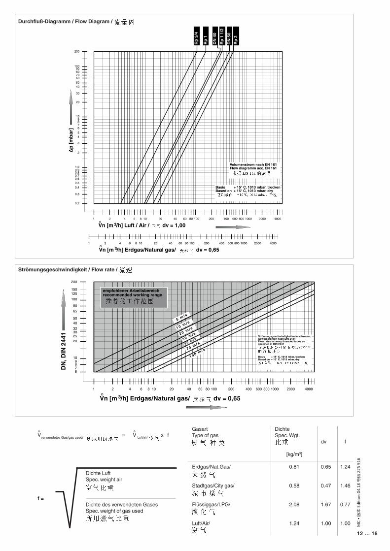
GasartType of gas
Erdgas/Nat.Gas/
Stadtgas/City gas/
Flüssiggas/LPG/
Luft/Air/
DichteSpec. Wgt.
[kg/m3]
0.81
0.58
2.08
1.24
dv
0.65
0.47
1.67
1.00
f
1.24
1.46
0.77
1.00
Dichte LuftSpec. weight air
Dichte des verwendeten GasesSpec. weight of gas used
f =
Vverwendetes Gas/gas used/ = ° V Luft/air/ x f °
Durchfluß-Diagramm / Flow Diagram /
Strömungsgeschwindigkeit / Flow rate /
0,2
0,3
0,40,50,60,70,8
1,00,9
2
3
456789
10
20
30
4050
200
100
60708090
Rp 3
/4
Rp 1
DN
40
Rp 1
1/2
DN
50
Rp 2
1 2 4 6 8 10 20 40 60 80 100 200 400 600 800 1000 2000 4000
1 2 4 6 8 10 20 40 60 80 100 200 400 600 800 1000 2000 4000
Vn [m /h] Luft / Air / dv = 1,00° 3
Vn [m /h] Erdgas/Natural gas/ dv = 0,65° 3
∆p [m
bar]
Basis + 15° C, 1013 mbar, trockenBased on + 15° C, 1013 mbar, dry
Volumenstrom nach EN 161Flow diagramm acc. EN 161
6789
10
20
30
4050
200
100
6580
1 2 4 6 8 10 20 40 60 80 100 200 400 600 800 1000 2000 4000
Vn [m /h] Erdgas/Natural gas/ dv = 0,65° 3
DN
, DIN
244
1
150125
1 0 0 m / s
5 m / s
1 0 m / s
3 0 m / s
empfohlener Arbeitsbereichrecommended working range
Strömungsgeschwindigkeiten in schweren Gewinderohren nach DIN 2441Flow rates in heavy threaded tubes asspecified in DIN 2441
Basis + 15° C, 1013 mbar, trockenBased on + 15° C, 1013 mbar, dry
25
32
7 0 m / s5 0 m / s2 0 m / s

13 … 16
MC
• 版
本 E
ditio
n 04
.18
号码
225
916
Ersatzteile / ZubehörSpare parts / Accessories
Verschlußschraube mit DichtringLocking screw and sealing ring
G 1/8G 1/4G 3/4
Einstellteller für HauptmengeAdjustment plate for main flow
Rp 3/4 – Rp 2, DN 40 – DN 50
HydraulikbremseHydraulic brake
Rp 3/4 – Rp 2, DN 40 – DN 50
EinsteckscheibeInsert washer
Rp 3/4 – Rp 2, DN 40 – DN 50
Dichtungen für Flanschenfor flanges sealing ring
DN 40DN 50
StiftschraubensatzSet of setscrews
M16 x 55 (DN 40 – DN 50)
Meßstutzen mit DichtringTest nipple with sealing ring
G 1/8G 1/4
SchutzkappeProtective cap
ZRDLE 4…/5 + ZRLE 4 …/5Rp 3/4 - Rp 2, DN 40 - DN 50 ErsatzmagnetReplacement solenoid
ZR … 407 - 410ZR … 415 - 420ZR … 4040 - 4050
Bestell-NummerOrdering No.
5 Stück/Set
5 Pieces/Set
230 395230 396230 402
231 790
223 158
231 564
2 Stück/Set2 Pieces/Set
231 600231 601
4 Stück/Set4 Pieces/Set
230 422
5 Stück/Set5 Pieces/Set
230 397230 298
5 Stück/Set5 Pieces/Set
231 785
auf Anfrage on request

14 … 16
MC
• 版
本 E
ditio
n 04
.18
号码
225
916
Arbeiten am Magnetventil dürfen nur von Fach-personal durchgeführt werden.
Flanschflächen schützen. Schrauben kreuzweise anziehen. Auf mecha-nisch spannunbgsfreien Einbau achten.
Direkter Kontakt zwi-schen Magentventil und dem aushärtendem Mau-erwerk, Betonwänden, Fußböden ist nicht zu-lässig.
Nennleistung bzw. Druck-sollwerte grundsätzlich am Gasdruckregelgerät einstellen. Leistungsspe-zifische Drosselung über das Magnetventil ZR.../5.
Grundsätz l ich nach Teileausbau/-umbau neue Dichtungen verwenden.
Rohrleitungsdichtheits-prüfung: Kugelhahn vor den Armaturen/ZR…/5 schließen
Nach Abschluß von Ar-beiten am ZR…/5: Dicht-heits- und Funktionskon-trolle durchführen.
Niemals Arbeiten durch-führen, wenn Gasdruck oder Spannung anliegt. Offenes Feuer vermeiden. Öffentliche Vorschriften beachten.
Bei Nichtbeachtung der Hinweise sind Personen- oder Sachfolgeschäden denkbar.
Work on the solenoid val-ve may only be performed by specialist staff.
Protect flange surfaces. Tighten screws cross-wise. Mount tension free.
Do not allow any direct contact between the sole-noid valve and hardened masonry, concrete walls or floors.
Always adjust nominal output or pressure set-points on the gas pres-sure regulator and perfor-mance-specific throttling using the ZR …/5.
Always use new seals after dismounting and mounting parts.
Pipeline leakage test: close ball valve upstream of fittings/ZR …/5.
On completion of work on the ZR…/5, perform a lea-kage and function test.
Never perform work if gas pressure or power is applied. No naked flame. Observe public regula-tions.
If these instructions are not heeded, the result may be personal injury or damage to property.
EN 88
p [mbar]
[m / h]3Vϒ
Safetyfirst
O.K.
额定功率与额定压力原则上应在燃气
压力调节器上进行调节。功能特殊的
节流部分通过电磁阀ZR .../5调节。
所有调节须按照锅炉/燃烧器制造商的使用手册进行。
Alle Einstellungen und Einstellwerte nur in Über-einstimmung mit der Be-triebsanleitung des Kes-sel-/Brennerherstellers ausführen.
Any adjustment and appli-cation-specific adjustment values must be made in accordance with the appli-ance-/boiler manufacturers instructions.

15 … 16
MC
• 版
本 E
ditio
n 04
.18
号码
225
916
Die Druckgeräterichtlinie (PED) und die Richtlinie über die Gesamtenergieef-fizienz von Gebäuden (EPBD) fordern eine regel-mässige Überprüfung der Wärmeerzeuger zur lang-fristigen Sicherstellung von hohen Nutzungsgraden und somit geringster Um-weltbelastung. Es besteht die Notwen-digkeit sicherheitsre-levante Komponenten nach Erreichen ihrer Nutzungsdauer aus-zutauschen:
The Pressure Equipment Directive (PED) and the Energy Performance of Buildings Directive (EPBD) require a periodic inspec-tion of heat generators in order to ensure a high degree of efficiency over a long term and, conse-quently, the least environ-mental pollution. It is necessary to re-place safety-relevant components after they have reached the end of their useful life:
为 了 长 期 保 障 最 高 的 使 用率 , 并 尽 可 能 减 少 环 境 污染,压力设备指令(PED)与建筑物能源效益指令(EPBD)均要求定期检查热发生器。对于和安全相关的组件,当达到其使用期限时,要予以更换。
Änderungen, die dem technischen Fortschritt dienen, vorbehalten / We reserve the right to make modifications in the course of technical development.保留为适应技术进步而更改的权利。
Sicherheitsrelevante KomponenteSafety relevant component和安全相关的组件
Konstruktionsbedingte LebensdauerDesigned Lifetime受制于设计的使用寿命
CEN-NormCEN-Standard欧洲标准化委员会规范Zyklenzahl
Operating cyclesCycle d’opération循环次数
Zeit [Jahre]Time [years]时间 [年]
Ventilprüfsysteme / Valve proving systems 阀门检漏系统
250.000 10 EN 1643
Gas/Gaz/气体Druckwächter / Pressure switch / 调压阀
50.000 10 EN 1854
Luft/Air/空气Druckwächter / Pressure switch / 调压阀
250.000 10 EN 1854
Gasmangelschalter / Low gas pressure switch燃气压力开关 N/A 10 EN 1854
Feuerungsmanager / Automatic burner control燃烧管理器 250.000 10 EN 298 (Gas/气体)
EN 230 (Öl/Oil/油UV-Flammenfühler1
Flame detector (UV probes)1
紫外线火焰传感器1 N/A
10.000Betriebsstunden Operating hours
工作小时
---
Gasdruckregelgeräte1 / Gas pressure regulators1
燃气压力开关1 N/A 15 EN 88-1EN 88-2
Gasventil mit Ventilprüfsystem2
Gas valve with valve testing system2
带有阀门检漏系统的气体阀2
nach erkanntem Fehlerafter error detection根据检测到的问题
EN 1643
Gasventil ohne Ventilprüfsystem2
Gas valve without valve testing system2
无阀门检漏系统的燃气阀2
50.000 - 200.000abhängig von der Nennweite
depends on diameter取决于公称尺寸
10 EN 161
Gas-Luft-Verbundsysteme / Gas-air ratio control system燃气空气联合系统 N/A 10 EN 88-1
EN 12067-2
1 Nachlassende Betriebseigenschaften wegen Alterung / Performance decrease due to ageing 操作性能将随着设备老化而下降2 Gasfamilien II, III / Gas families II, III / II, III类燃气N/A nicht anwendbar / not applicable / (无法使用)
Karl Dungs GmbH & Co. KG Karl-Dungs-Platz 1 D-73660 Urbach, GermanyTelefon +49 (0)7181-804-0Telefax +49 (0)7181-804-166
e-mail [email protected] www.dungs.com

16 … 16
MC
• 版
本 E
ditio
n 04
.18
号码
225
916
Karl Dungs GmbH & Co. KG Karl-Dungs-Platz 1 D-73660 Urbach, GermanyTelefon +49 (0)7181-804-0Telefax +49 (0)7181-804-166
e-mail [email protected] www.dungs.com