Embed Size (px)
Citation preview

Motion controlLexium integrated drives
Catalogue
September 2011

All technical information about products listed in this catalogue are now available on:
www.schneider-electric.com
Browse the “product data sheet” to check out : characteristics, dimensions, curves, ... and also the links to the user guides and
the CAD fi les.
1 From the home page, type the model number* into the “Search” box.
2 Under ”All” tab, click the model number that interests you.
* type the model number without any blank, replace “ p ” by “*”

U
C
t1
G
Rt'1t2 t'2
U
C
t1
G
R
t'1t2 t'2
89,5
80
82
22,5
78
3 The product data sheet displays.
You can get this information in one single pdf fi le.
Discover this product
p Characteritics p Functions p Connection p Dimensions p Download &
DocumentsOther products
p Help me to chooseAccessories
p Plug p Sockets
Example : Zelio Time
data sheet
Example : Zelio Time
data sheet
Example : Zelio Time
data sheet

2
1
2
3
4
5
6
7
8
9
10
1
2
3
4
5
6
7
8
9
10
1
2
3
4
5
6
7
8
9
10
3
Contents 0 Motion control Lexium integrated drivesb
Presentation of the offer . . . . . . . . . . . . . . . . . . . . . . . . . . . . . . . . . . . . . . page 4bIL p 1 integrated drives for CANopen, PROFIBUS DP
and RS 485 serial linkvPresentation . . . . . . . . . . . . . . . . . . . . . . . . . . . . . . . . . . . . . . . . . . . . . . . page 6vILA1 integrated drives with AC synchronous servo motor . . . . . . . . . . . . page 10vILE1 integrated drives with DC brushless motor . . . . . . . . . . . . . . . . . . . page 12vILS1 integrated drives with 3-phase stepper motor . . . . . . . . . . . . . . . . page 14b
IL p 2 integrated drives for DeviceNet, EtherCAT, EtherNet/IP,
Modbus TCP and Ethernet POWERLINKvPresentation . . . . . . . . . . . . . . . . . . . . . . . . . . . . . . . . . . . . . . . . . . . . . . page 16vILA2 integrated drives with AC synchronous servo motor . . . . . . . . . . . . page 20vILE2 integrated drives with DC brushless motor . . . . . . . . . . . . . . . . . . . page 22vILS2 integrated drives with 3-phase stepper motor . . . . . . . . . . . . . . . . page 24b
ILS1 integrated drives with I/O interface for motion sequencevPresentation . . . . . . . . . . . . . . . . . . . . . . . . . . . . . . . . . . . . . . . . . . . . . . page 26vReferences . . . . . . . . . . . . . . . . . . . . . . . . . . . . . . . . . . . . . . . . . . . . . . page 30b
ILS1 integrated drives with pulse/direction (P/D) interfacevPresentation . . . . . . . . . . . . . . . . . . . . . . . . . . . . . . . . . . . . . . . . . . . . . . page 32vReferences . . . . . . . . . . . . . . . . . . . . . . . . . . . . . . . . . . . . . . . . . . . . . . page 34b
Accessories for ILA, ILE and ILS integrated drives . . . . . . . . . . . . . . . . page 36bOption: GBp planetary gearboxes . . . . . . . . . . . . . . . . . . . . . . . . . . . . . page 40bILPp R integrated drives for RS 485 serial linkv
Presentation . . . . . . . . . . . . . . . . . . . . . . . . . . . . . . . . . . . . . . . . . . . . . . page 44vReferences . . . . . . . . . . . . . . . . . . . . . . . . . . . . . . . . . . . . . . . . . . . . . . page 48b
ILTp A integrated drives for CANopen machine busvPresentation . . . . . . . . . . . . . . . . . . . . . . . . . . . . . . . . . . . . . . . . . . . . . . page 50vReferences . . . . . . . . . . . . . . . . . . . . . . . . . . . . . . . . . . . . . . . . . . . . . . page 54b
ILTp V integrated drives with pulse/direction (P/D) interfacevPresentation . . . . . . . . . . . . . . . . . . . . . . . . . . . . . . . . . . . . . . . . . . . . . . page 56vReferences . . . . . . . . . . . . . . . . . . . . . . . . . . . . . . . . . . . . . . . . . . . . . . page 58b
Accessories for ILP and ILT integrated drives . . . . . . . . . . . . . . . . . . . . page 60
1
2
3
4
5
6
7
8
10
1
2
3
4
5
6
7
8
10
1
2
3
4
5
6
7
8
10

4
Presentation Motion controlLexium integrated drives
Presentation
Lexium integrated drives are used to create decentralized motion control solutions in very compact units.
They consist of a motor and control electronics. They are controlled via a communication bus, a pulse/direction (P/D) interface or an I/O interface (for the “Motion sequence” operating mode).
Lexium integrated drives are used as decentralized drives in machine building. When combined with a Schneider Electric Lexium Controller or a PLC, they can be used to create complex control system architectures simply and at minimum cost. Ready-to-use function blocks are available for programming movements with Schneider Electric or third-party motion controllers.
Maximum compactness
The motor and control electronics form a compact unit. This decentralized unit does not require any space in the enclosure for the control electronics, thus reducing the size of the machine.
Simple to install and commission
Integration of the motor and the control electronics reduces the installation costs and simplifi es incorporation of electromagnetic compatibility. In addition, Lexium CT PC software provides rapid commissioning.
Optimum fl exibility to adapt to your application
The integrated drives can be equipped with an AC synchronous servo motor, a DC brushless motor or a stepper motor, thus providing numerous possibilities for use in a wide variety of applications.Depending on the technology used, they can thus meet requirements for dynamic performance, fl exibility or precision in motion control applications.
Open communication with control system architectures
Depending on the model, Lexium integrated drives incorporate as standard the main communication protocols used in industry for increased performance of your applications:
b
CANopen, PROFIBUS DP, DeviceNet, EtherCAT, EtherNet/IP, Ethernet POWERLINK and Modbus TCP communication buses and networks
b
RS 485 serial link
Integrated drives with stepper motor are also available with a pulse/direction (P/D) interface or an I/O interface for the motion sequence.
This open communication concept enables integration in numerous control system architectures.
Integrated safety
The integrated Safe Torque Off (Power Removal) safety function enables a category 0 or 1 stop to be performed in accordance with standard IEC/EN 60204-1 without external power protection devices. The integrated drive does not have to be switched off, which reduces the system costs and the restart times. The drive complies with the requirements of the following standards: IEC/EN 61508 SIL2, ISO 13849-1 performance level “d” (PL d) and IEC/EN 61800-5-2 (STO).
Applications
Lexium integrated drives are suitable for the most common applications, including:
bPackaging
b
Material handling, labelling
bTextiles
b
Printing
bElectronic components
b
Medical technology
Material handling application
Labelling application
Connections
Control electronics Motor
Lexium drive incorporating control electronics, motor and connectors
5
Presentation (continued) Motion controlLexium integrated drivesLexium CT commissioning software
Presentation (continued)
The commissioning time for Lexium integrated drives is considerably reduced using the Lexium CT (Lexium Commissioning Tool) PC software.
It is used for commissioning, parameter setting, simulation and diagnostics.
Functions
Lexium CT PC software includes the following functions:
bEntry and display of parameters
b
Archiving and duplication of parameters
bDisplay of status information
b
Positioning of the motor via the PC
bInitiation of homing movements
b
Access to all documented parameters
bFault diagnostics
b
Controller optimization (for ILA integrated drive)
Required confi guration
Lexium CT software runs on a PC with the Microsoft Windows® 2000/XP/Vista operating systems. The integrated drive is commissioned via the communication interface.
Download
Lexium CT software can be downloaded from our website: www.schneider-electric.com.
6
Presentation
Lexium IL p 1 integrated drives comprise a motor, control electronics and a communication interface for:
b
CANopen DS301 machine bus (ILp 1F)
bPROFIBUS DP V0 fi eldbus (ILp 1B)
b
RS 485 serial link (ILp 1R)The communication bus interface is used for setting parameters and controlling the integrated drives, as well as for commissioning using Lexium CT software.
Lexium ILp 1 integrated drives also have an RS 485 serial link interface and an interface for four 24 V signals, which can be confi gured as either inputs or outputs to suit application requirements.They also include the Safe Torque Off (Power Removal) safety function as standard, which prevents unintended motor operation.
The control section comprises control electronics and a power stage which share a common power supply. Lexium ILp 1 integrated drives can operate on a 24 V to 36 V c supply.
Three motor technologies are offered to cover a wide range of applications.
Adaptability assured by three motor technologies
The Lexium ILp 1 integrated drive range offers three motor technologies to meet the requirements for dynamic performance, fl exibility or precision in a wide variety of applications:
ILA1: the integrated drive for dynamic processes
The ILA1 integrated drive is equipped with an AC synchronous servo motor. This motor features high dynamic performance, as it can be temporarily boosted when accelerating.
Application example: bottlingBottles are transported on a conveyor up to the fi lling point, where their presence is detected by a sensor.The Lexium ILA1 drive activates a pump to start fi lling the bottle then ensures accurate fi lling and instant stop to avoid overfl owing by means of its closed loop function.
ILE1: the integrated drive for automatic format adjustment
The ILE1 integrated drive is equipped with a DC brushless motor. This motor has a high automatic holding torque, which makes the use of a holding brake unnecessary in the majority of applications. The control electronics incorporated in the ILE1 drive provide absolute encoder functionality.
Application example: ground-mounted solar power plantsThe latest solar power plants are equipped with biaxial tracking systems (azimuth/zenith). Each axis is controlled by two Lexium ILE1 integrated drives. The Lexium ILE1 drive was chosen for its high holding torque and because it totally eliminates the need for electrical cabinets.
ILS1: the integrated drive for short range positioning
With its 3-phase stepper motor, the ILS1 integrated drive offers high torque values at low rotation speeds.In rotation speed mode, it has excellent stability characteristics and also enables high resolution positioning tasks.Commissioning an ILS1 integrated drive with stepper motor is simple as it does not require any confi guration of the control loop.
Application example: labelling machineThe Lexium ILS integrated drive's high torque is used to control the unrolling speed of the label roll.
Presentation Motion controlLexium integrated drivesILp 1 for CANopen, PROFIBUS DP, RS 485
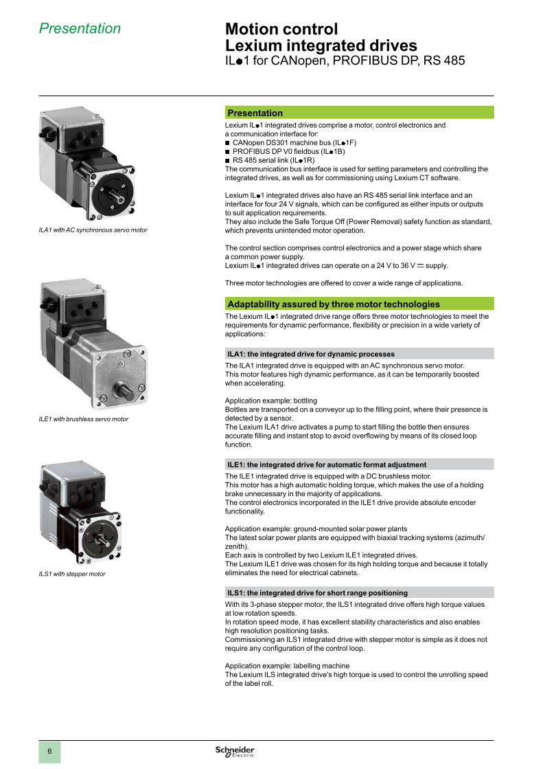
ILS1 with stepper motor
ILA1 with AC synchronous servo motor
ILE1 with brushless servo motor

7
Presentation (continued) Motion controlLexium integrated drivesIL p 1 for CANopen, PROFIBUS DP, RS 485
InterfacesCommunication bus interface
Depending on the model, the following communication buses can be connected:
bCANopen machine bus (protocol DS301)
b
PROFIBUS DP V0 fi eldbus (data format according to Profi drive V2.0 PPO type 2)
bRS 485 serial link
The communication bus interface is used for setting parameters and controlling the integrated drive. It is also used as an option for connecting the terminal when commissioning the integrated drive using Lexium CT PC software (see page 5). A suitable communication bus converter is then required, for example CAN/USB, PROFIBUS DP/USB or RS 485/USB.
RS 485 serial link interface
The Lexium IL p 1 integrated drive is commissioned by default via the RS 485 serial link interface. This interface also accesses the drive's integrated control/monitoring function. This function can also be accessed via the Lexium CT PC software.
The communication bus and RS 485 serial link can be connected simultaneously.
Interface for 24 V signals
Four 24 V signals are available, confi gurable as inputs or outputs. They can also be used for predefi ned functions such as limit switches or reference sensors.They can be used by the master controller.
The 24 V power for the outputs is provided internally via the integrated drive's power supply.
Interface for integrated Safe Torque Off function
The Safe Torque Off (Power Removal) safety function enables a category 0 or 1stop to be performed in accordance with IEC/EN 60204-1 and/or prevents unintended motor operation in accordance with IEC/EN 61508 level SIL2, ISO 13849-1 performance level “d” (PL d) and IEC/EN 61800-5-2 (STO).No additional power protection is necessary.The Lexium ILp 1 integrated drive can remain powered up, which reduces system costs and the restart time.
The Safe Torque Off function is activated via two redundant 24 V input signals (active in OFF state).
Special technical featuresILA1 with AC synchronous servo motor
b
High dynamic performance and high peak torque
bChoice of:
v
single turn high resolution encoder, 16,384 points/turn (0.02°)
vmultiturn high resolution encoder, 16,384 points/turn (0.02°) for 4096 turns
b
Integrated holding brake available as an option
bPlanetary gearbox available as an option
ILE1 with DC brushless motor
b
High automatic holding torque
bAbsolute encoder: no homing required after switching off/on
b
Can be equipped with integral straight-tooth gearbox or tapered worm gearbox
bPlanetary gearbox available as an option
ILS1 with 3-phase stepper motor
b
High continuous stall torque
bGood speed stability characteristics
b
High encoder accuracy (0.018°)
bHolding brake available as an option for ILS1p 85 integrated drive
b
Planetary gearbox available as an option
8
Presentation (continued) Motion controlLexium integrated drivesILp 1 for CANopen, PROFIBUS DP, RS 485
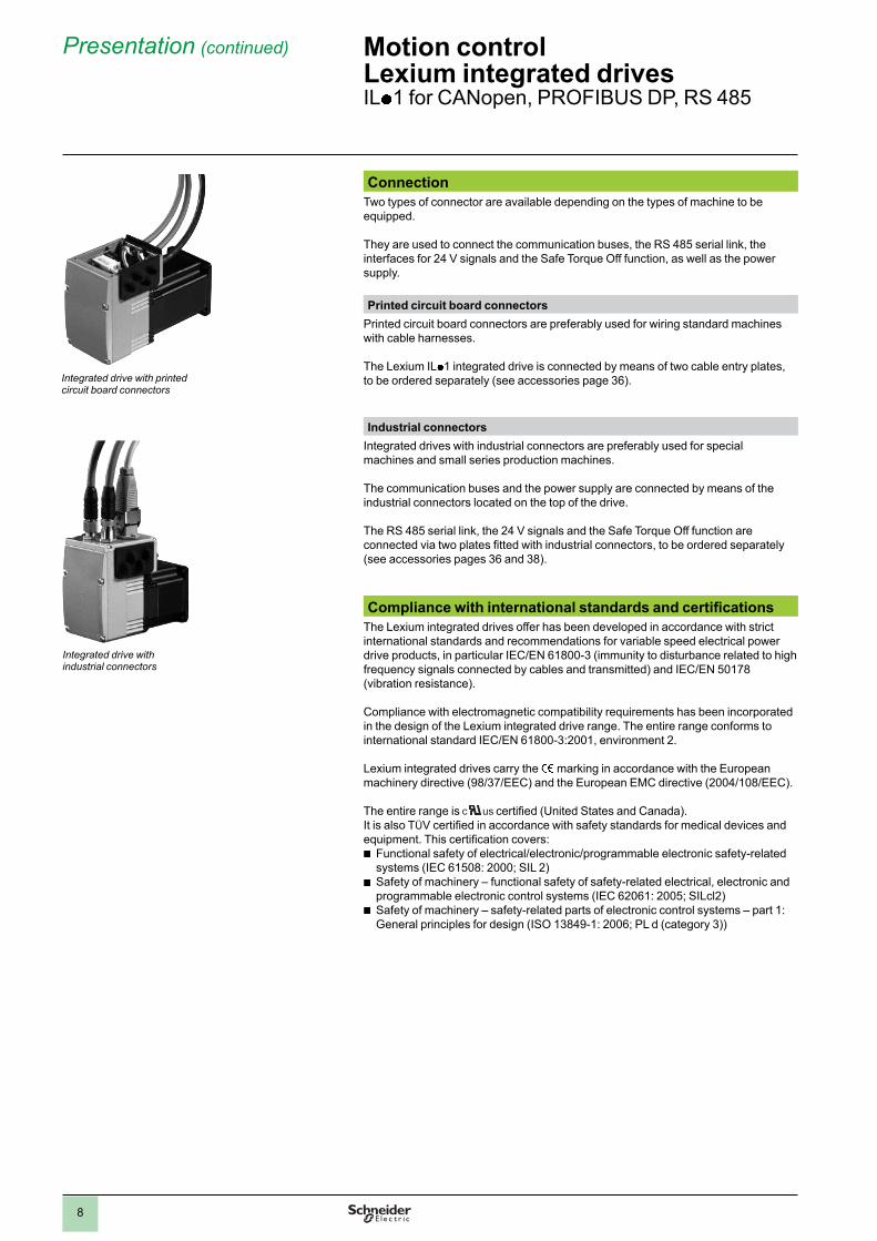
Connection
Two types of connector are available depending on the types of machine to be equipped.
They are used to connect the communication buses, the RS 485 serial link, the interfaces for 24 V signals and the Safe Torque Off function, as well as the power supply.
Printed circuit board connectors
Printed circuit board connectors are preferably used for wiring standard machines with cable harnesses.
The Lexium ILp 1 integrated drive is connected by means of two cable entry plates, to be ordered separately (see accessories page 36).
Industrial connectors
Integrated drives with industrial connectors are preferably used for special machines and small series production machines.
The communication buses and the power supply are connected by means of the industrial connectors located on the top of the drive.
The RS 485 serial link, the 24 V signals and the Safe Torque Off function are connected via two plates fi tted with industrial connectors, to be ordered separately (see accessories pages 36 and 38).
Compliance with international standards and certifi cations
The Lexium integrated drives offer has been developed in accordance with strict international standards and recommendations for variable speed electrical power drive products, in particular IEC/EN 61800-3 (immunity to disturbance related to high frequency signals connected by cables and transmitted) and IEC/EN 50178 (vibration resistance).
Compliance with electromagnetic compatibility requirements has been incorporated in the design of the Lexium integrated drive range. The entire range conforms to international standard IEC/EN 61800-3:2001, environment 2.
Lexium integrated drives carry the e
marking in accordance with the European machinery directive (98/37/EEC) and the European EMC directive (2004/108/EEC).
The entire range is certifi ed (United States and Canada). It is also TÜV certifi ed in accordance with safety standards for medical devices and equipment. This certifi cation covers:
b
Functional safety of electrical/electronic/programmable electronic safety-related systems (IEC 61508: 2000; SIL 2)
b
Safety of machinery – functional safety of safety-related electrical, electronic and programmable electronic control systems (IEC 62061: 2005; SILcl2)
b
Safety of machinery – safety-related parts of electronic control systems – part 1: General principles for design (ISO 13849-1: 2006; PL d (category 3))
Integrated drive with printed circuit board connectors
Integrated drive with industrial connectors

9
Presentation (continued) Motion controlLexium integrated drivesIL p 1 for CANopen, PROFIBUS DP, RS 485
Main functions
Lexium IL p 1 integrated drives include the main functions required for motion control, in particular:
Confi guration by means of parameter switches
The following settings can be performed using the parameter switches in the integrated drive:
b
CANopen DS301 and RS 485 serial link:
vsetting of the communication bus address
v
setting of the transmission rate
vend of line termination activation
v
setting of the pulse/direction (P/D) signals or encoder (A/B) signals to “electronic gearbox” mode for integrated drive ILA1p 57 equipped with a single turn encoder
b
PROFIBUS DP V0:
vsetting of the fi eldbus address
v
end of line termination activation
Operating modes
The following operating modes can be set via the communication bus: b electronic gearbox (for drive ILA1p 57 with single turn encoder) b speed profi le b manual (JOG) b point-to-point b homing
Other operating modes can be activated via the communication bus or with Lexium CT PC software:
b activation of the motor brake
b reversal of direction of rotation of the motor b setting of the motion profi le via the profi le generator
b setting of the motor phase current b triggering of the Quick Stop function b fast position capture via an input signal b confi guration of I/O signals b scaling of drive internal units to user units
b control/monitoring functions
Note: For details of available functions, please visit our website www.schneider-electric.com.
2
1
3
4
5
6
7
8
9
10
2
1
3
4
5
6
7
8
9
10
10
Description Motion controlLexium integrated drivesILp 1 for CANopen, PROFIBUS DP, RS 485ILA1 with AC synchronous servo motor
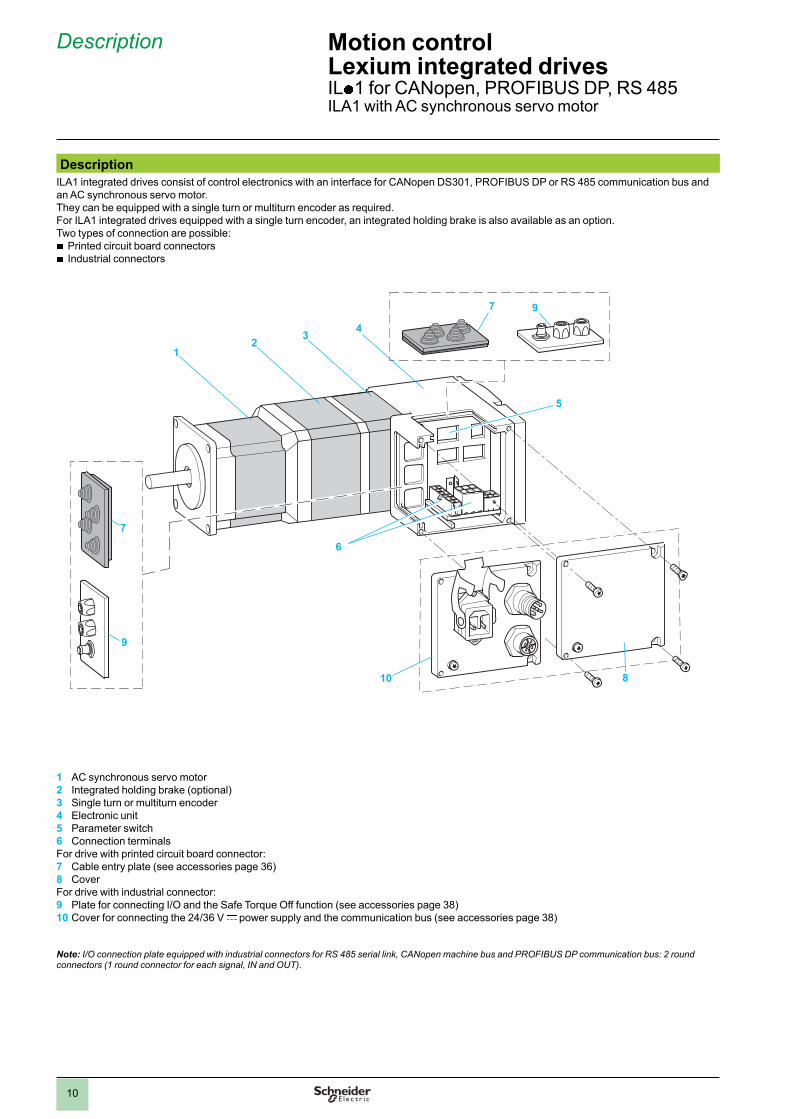
Description
ILA1 integrated drives consist of control electronics with an interface for CANopen DS301, PROFIBUS DP or RS 485 communication bus and an AC synchronous servo motor. They can be equipped with a single turn or multiturn encoder as required.For ILA1 integrated drives equipped with a single turn encoder, an integrated holding brake is also available as an option.Two types of connection are possible:
b
Printed circuit board connectors
bIndustrial connectors
1 AC synchronous servo motor2 Integrated holding brake (optional)3 Single turn or multiturn encoder4 Electronic unit5 Parameter switch6 Connection terminals For drive with printed circuit board connector:7 Cable entry plate (see accessories page 36)8 Cover For drive with industrial connector:9 Plate for connecting I/O and the Safe Torque Off function (see accessories page 38)10 Cover for connecting the 24/36 V c power supply and the communication bus (see accessories page 38)
Note: I/O connection plate equipped with industrial connectors for RS 485 serial link, CANopen machine bus and PROFIBUS DP communication bus: 2 round connectors (1 round connector for each signal, IN and OUT).
7
9
12
34
7 9
5
810
6
2
1
3
4
5
6
7
8
9
10
2
1
3
4
5
6
7
8
9
10
11
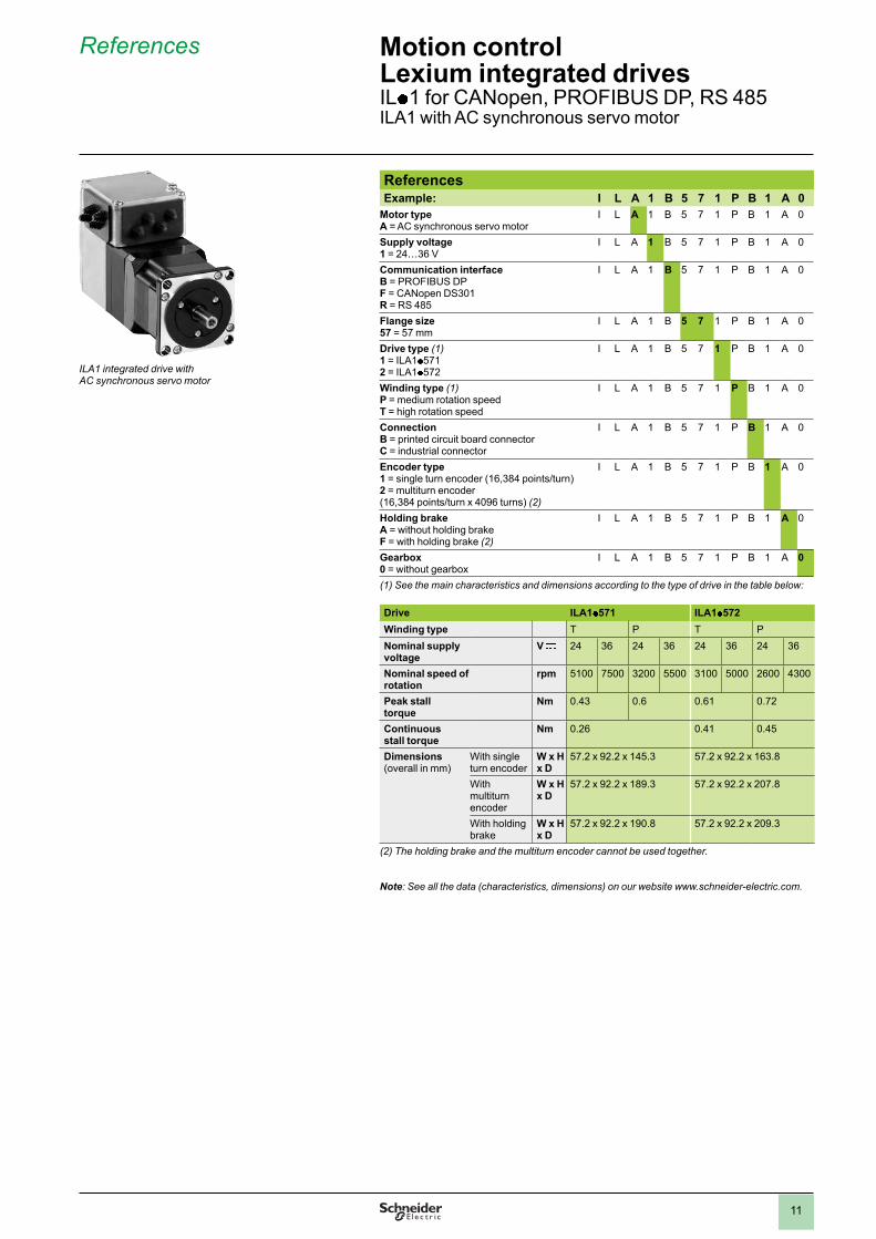
References Example: I L A 1 B 5 7 1 P B 1 A 0
Motor typeA = AC synchronous servo motor
I L A 1 B 5 7 1 P B 1 A 0
Supply voltage1 = 24…36 V
I L A 1 B 5 7 1 P B 1 A 0
Communication interfaceB = PROFIBUS DPF = CANopen DS301R = RS 485
I L A 1 B 5 7 1 P B 1 A 0
Flange size57 = 57 mm
I L A 1 B 5 7 1 P B 1 A 0
Drive type (1)1 = ILA1p 5712 = ILA1p 572
I L A 1 B 5 7 1 P B 1 A 0
Winding type (1)P = medium rotation speedT = high rotation speed
I L A 1 B 5 7 1 P B 1 A 0
ConnectionB = printed circuit board connectorC = industrial connector
I L A 1 B 5 7 1 P B 1 A 0
Encoder type1 = single turn encoder (16,384 points/turn)2 = multiturn encoder (16,384 points/turn x 4096 turns) (2)
I L A 1 B 5 7 1 P B 1 A 0
Holding brakeA = without holding brakeF = with holding brake (2)
I L A 1 B 5 7 1 P B 1 A 0
Gearbox0 = without gearbox
I L A 1 B 5 7 1 P B 1 A 0
(1) See the main characteristics and dimensions according to the type of drive in the table below:
Drive ILA1p 571 ILA1 p 572
Winding type T P T P
Nominal supplyvoltage
V c 24 36 24 36 24 36 24 36
Nominal speed of rotation
rpm 5100 7500 3200 5500 3100 5000 2600 4300
Peak stall torque
Nm 0.43 0.6 0.61 0.72
Continuous stall torque
Nm 0.26 0.41 0.45
Dimensions (overall in mm)
With single turn encoder
W x H x D
57.2 x 92.2 x 145.3 57.2 x 92.2 x 163.8
With multiturn encoder
W x H x D
57.2 x 92.2 x 189.3 57.2 x 92.2 x 207.8
With holding brake
W x H x D
57.2 x 92.2 x 190.8 57.2 x 92.2 x 209.3
(2) The holding brake and the multiturn encoder cannot be used together.
Note: See all the data (characteristics, dimensions) on our website www.schneider-electric.com.
References Motion controlLexium integrated drivesIL p 1 for CANopen, PROFIBUS DP, RS 485ILA1 with AC synchronous servo motor
ILA1 integrated drive with AC synchronous servo motor

12
Description Motion controlLexium integrated drivesILp 1 for CANopen, PROFIBUS DP, RS 485ILE1 with DC brushless motor
Description
ILE1 integrated drives consist of control electronics with an interface for CANopen DS301, PROFIBUS DP or RS 485 communication bus and a DC brushless motor. They are available with straight-tooth gearbox or tapered worm gearbox and printed circuit board connectors or industrial connectors.
5
7
1 2
5 7
3
6
8
4
1 DC brushless motor2 Electronic unit3 Parameter switch4 Connection terminalsFor integrated drive with printed circuit board connector: 5 Cable entry plate (see accessories page 36)6 CoverFor integrated drive with industrial connector:
7 Plate for connecting I/O and the Safe Torque Off function (see accessories page 38)8 Cover for connecting the 24/36 V c power supply and the communication bus (see accessories page 38)
Note: I/O connection plate equipped with industrial connectors for RS 485 serial link, CANopen machine bus and PROFIBUS DP communication bus: 2 round connectors (1 round connector for each signal, IN and OUT).
13
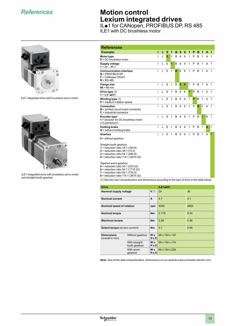
References Example: I L E 1 B 6 6 1 P B 1 A 1
Motor typeE = DC brushless motor
I L E 1 B 6 6 1 P B 1 A 1
Supply voltage1 = 24…36 V
I L E 1 B 6 6 1 P B 1 A 1
Communication interfaceB = PROFIBUS DPF = CANopen DS301R = RS 485
I L E 1 B 6 6 1 P B 1 A 1
Flange size66 = 66 mm
I L E 1 B 6 6 1 P B 1 A 1
Drive type (1)1 = ILE1p 661
I L E 1 B 6 6 1 P B 1 A 1
Winding type (1)P = medium rotation speed
I L E 1 B 6 6 1 P B 1 A 1
ConnectionB = printed circuit board connectorC = industrial connector
I L E 1 B 6 6 1 P B 1 A 1
Encoder type1 = encoder for DC brushless motor (12 points/turn)
I L E 1 B 6 6 1 P B 1 A 1
Holding brakeA = without holding brake
I L E 1 B 6 6 1 P B 1 A 1
Gearbox I L E 1 B 6 6 1 P B 1 A 1
0 = without gearbox
Straight-tooth gearbox1 = reduction ratio 18:1 (160:9)2 = reduction ratio 38:1 (75:2)3 = reduction ratio 54:1 (490:9)4 = reduction ratio 115:1 (3675:32)
Tapered worm gearbox5 = reduction ratio 24:1 (525:22)6 = reduction ratio 54:1 (1715:32)7 = reduction ratio 92:1 (735:5)8 = reduction ratio 115:1 (3675:32)
(1) See the main characteristics and dimensions according to the type of drive in the table below:
Drive ILE1p 661
Nominal supply voltage V c 24 36
Nominal current A 4.7 5.1
Nominal speed of rotation rpm 4000 4800
Nominal torque Nm 0.175 0.24
Maximum torque Nm 0.26 0.36
Detent torque (at zero current) Nm 0.1 0.06
Dimensions (overall in mm)
Without gearbox W x H x D
66 x 104 x 122
With straight-tooth gearbox
W x H x D
66 x 104 x 174
With worm gearbox
W x H x D
66 x 104 x 229
Note: See all the data (characteristics, dimensions) on our website www.schneider-electric.com.
References Motion controlLexium integrated drivesIL p 1 for CANopen, PROFIBUS DP, RS 485ILE1 with DC brushless motor
ILE1 integrated drive with brushless servo motor and straight-tooth gearbox
ILE1 integrated drive with brushless servo motor

14
Description
ILS1 integrated drives consist of control electronics with an interface for CANopen DS301, PROFIBUS DP or RS 485 communication bus and a 3-phase stepper motor. For ILS1p 85 integrated drives, an integrated holding brake is also available as an option.Two types of connection are possible:
b
Printed circuit board connectors
bIndustrial connectors
1
2
5 7
3
6
8
4
5
7
1 3-phase stepper motor2 Electronic unit3 Parameter switch4 Connection terminalsFor drive with printed circuit board connector:5 Cable entry plate (see accessories page 36)6 CoverFor drive with connector for industrial circuit:7 Plate for connecting I/O and the Safe Torque Off function (see accessories page 38)8 Cover for connecting the 24/36 V c power supply and the communication bus (see accessories page 38)
Note: I/O connection plate equipped with industrial connectors for RS485 serial link, CANopen machine bus and PROFIBUS DP communication bus: 2 round connectors (1 round connector for each signal, IN and OUT).
Description Motion controlLexium integrated drivesILp 1 for CANopen, PROFIBUS DP, RS 485ILS1 with 3-phase stepper motor

15
References Example: I L S 1 B 5 7 1 P B 1 A 0
Motor typeS = 3-phase stepper motor
I L S 1 B 5 7 1 P B 1 A 0
Supply voltage1 = 24…36 V
I L S 1 B 5 7 1 P B 1 A 0
Communication interfaceB = PROFIBUS DPF = CANopen DS301R = RS 485
I L S 1 B 5 7 1 P B 1 A 0
Flange size57 = 57 mm85 = 85 mm
I L S 1 B 5 7 1 P B 1 A 0
Drive type (1)1 = ILS1p p p 12 = ILS1p p p 23 = ILS1p p p 3
I L S 1 B 5 7 1 P B 1 A 0
Winding type (1)P = medium rotation speedT = high rotation speed (2)
I L S 1 B 5 7 1 P B 1 A 0
ConnectionB = printed circuit board connectorC = industrial connector
I L S 1 B 5 7 1 P B 1 A 0
Sensor type1 = reference pulse sensor (Zero marker)
I L S 1 B 5 7 1 P B 1 A 0
Holding brakeA = without holding brakeF = with holding brake (3)
I L S 1 B 5 7 1 P B 1 A 0
Gearbox0 = without gearbox
I L S 1 B 5 7 1 P B 1 A 0
(1) See the main characteristics and dimensions according to the type of drive in the table below:
Drive ILS1p 571 ILS1 p 572 ILS1p 573
Winding type P P P
Nominal speed of rotation
rpm 1000 600 450
Maximum torque Nm 0.45 0.9 1.5
Holding torque Nm 0.51 1.02 1.7
Dimensions (overall in mm)
W x H x D
57.2 x 92.2 x 101.9 57.2 x 92.2 x 115.9 57.2 x 92.2 x 138.9
Drive ILS1p 851 ILS1 p 852 ILS1p 853
Winding type P P P T
Nominal speed of rotation
rpm 450 200 120 300
Maximum torque Nm 2 4 6 4.5
Holding torque Nm 2 4 6 4.5
Dimensions (overall in mm)
Without holding brake
W x H x D
85 x 119.6 x 140.6 85 x 119.6 x 170.6 85 x 119.6 x 200.6
With holding brake
W x H x D
85 x 119.6 x 187.3 85 x 119.6 x 217.3 85 x 119.6 x 247.3
(2) Twinding only available for integrated drive with 85 mm fl ange (ILS1p 853).(3) Holding brake only available for integrated drive with 85 mm fl ange (ILS1p 85).
Note: See all the data (characteristics, dimensions) on our website www.schneider-electric.com.
References Motion controlLexium integrated drivesIL p 1 for CANopen, PROFIBUS DP, RS 485ILS1 with 3-phase stepper motor
ILS1 integrated drive with stepper motor

16
Presentation
Lexium ILp 2 integrated drives comprise a motor, control electronics and a communication interface for:
b
DeviceNet (ILp 2D)
bEtherCAT (ILp 2E)
b
EtherNet/IP (ILp 2K)
bModbus TCP (ILp 2T)
b
Ethernet POWERLINK (ILp 2P)The communication bus interface is used for setting parameters and controlling the integrated drives, as well as for commissioning using Lexium CT software.
Lexium ILp 2 integrated drives also have an RS 485 serial link interface and an interface for four 24 V signals, which can be confi gured as either inputs or outputs to suit application requirements.They also include the Safe Torque Off (Power Removal) safety function as standard, which prevents unintended motor operation.
The control section comprises control electronics and a power stage which share a common power supply. Lexium ILp 2 integrated drives can operate on a 24 V to 48 V c supply. Three motor technologies are offered to cover a wide range of applications.
Adaptability assured by three motor technologies
The Lexium ILp 2 integrated drive range offers three motor technologies to meet requirements for dynamic performance, fl exibility or precision in a wide variety of applications:
ILA2: the integrated drive for dynamic processes
The ILA2 integrated drive is equipped with an AC synchronous servo motor. This motor features high dynamic performance, as it can be temporarily boosted when accelerating.
Application example: manufacture of CDs/DVDsFrom the pressing of the CD or DVD right through to the end of its manufacture, the process is totally automated using Lexium ILA2 integrated drives, which increase productivity and reduce the production area by approximately 10%.
ILE2: the integrated drive for automatic format adjustment
The ILE2 integrated drive is equipped with a DC brushless motor. This motor has a high automatic holding torque. This makes the use of a holding brake unnecessary in the majority of applications. The control electronics incorporated in the ILE2 drive provide absolute encoder functionality.
Application example: manufacture of solar cellsElectrical circuits are printed using a silkscreen process. Lexium ILE2 integrated drives are used for conveying. Dynamic performance is signifi cantly improved and the wiring time is reduced. Other integrated drives, such as Lexium ILS2, are also used for precise positioning, or Lexium ILA2 for the printing process.
ILS2: the integrated drive for short range positioning
With its 3-phase stepper motor, the ILS2 integrated drive offers high torque values at low rotation speeds. It is mainly used in rotation speed mode with excellent stability characteristics and also for high resolution positioning. The commissioning of ILS2 drives with stepper motor is simple as it does not require any confi guration of the control loop.
Application example: wood processingIn applications using multi-blade circular saws, the planks are measured using lasers. They are positioned using linear axes equipped with a Lexium ILS2 integrated drive. Because of the harsh environmental conditions, the control cabinets are located some distance from the machinery. This concept of decentralization considerably reduces the wiring.
Presentation Motion controlLexium integrated drivesILp 2 for DeviceNet, EtherCAT, EtherNet/IP, Modbus TCP, Ethernet POWERLINK
ILE2 with brushless servo motor
ILA2 with AC synchronous servo motor
ILS2 with stepper motor

17
Presentation (continued) Motion controlLexium integrated drivesIL p 2 for DeviceNet, EtherCAT, EtherNet/IP, Modbus TCP, Ethernet POWERLINK
Interfaces
Communication bus interface
Depending on the model, the following communication buses can be connected:
bDeviceNet
b
EtherCAT (according to IEEE 802.3)
bEtherNet/IP (according to IEEE 802.3)
b
Modbus TCP (according to IEEE 802.3)
bEthernet POWERLINK (according to IEEE 802.3)
The communication bus interface is used for setting parameters and controlling the integrated drive. It is also used as an option for connecting the terminal when commissioning the integrated drive using Lexium CT PC software (see page 5).
Connection to the DeviceNet fi eldbus, available depending on the model, provides access to the ADR (Auto Device Replacement) function. If maintenance is required, this function enables drives to be replaced without having to redefi ne the parameters.
The communication bus and RS 485 serial link can be connected simultaneously.
RS 485 serial link interface
The Lexium ILp 2 integrated drive is commissioned by default via the RS 485 serial link interface.
This interface also accesses the control/monitoring function included in the drive. This function can also be accessed via the Lexium CT PC software.
The communication bus and RS 485 serial link can be connected simultaneously.
Interface for 24 V signals
Four 24 V signals are available, confi gurable as inputs or outputs. They can also be used to set the parameters of predefi ned functions such as limit switch detection.
They can be used by the master controller.
The 24 V power for the outputs is provided internally via the integrated drive's power supply.
Interface for integrated Safe Torque Off function
The Safe Torque Off (Power Removal) safety function enables a category 0 or 1 stop to be performed in accordance with standard IEC/EN 60204-1 and/or prevents unintended motor operation in accordance with standard IEC/EN 61508 level SIL2, ISO 13849-1 performance level “d” (PL d) and IEC/EN 61800-5-2 (STO).
No additional power protection option is necessary. The Lexium IL p 1 integrated drive can remain powered up, which reduces system costs and the restart time.
The Safe Torque Off function is activated via two redundant 24 V input signals (active in OFF state).
18
Presentation (continued) Motion controlLexium integrated drivesILp 2 for DeviceNet, EtherCAT, EtherNet/IP, Modbus TCP, Ethernet POWERLINK
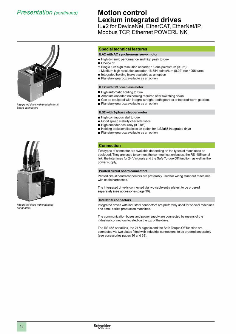
Integrated drive with printed circuit board connectors
Special technical features
ILA2 with AC synchronous servo motor
b
High dynamic performance and high peak torque
bChoice of:
v
Single turn high resolution encoder, 16,384 points/turn (0.02°)
vMultiturn high resolution encoder, 16,384 points/turn (0.02°) for 4096 turns
b
Integrated holding brake available as an option
bPlanetary gearbox available as an option
ILE2 with DC brushless motor
b
High automatic holding torque
bAbsolute encoder: no homing required after switching off/on
b
Can be equipped with integral straight-tooth gearbox or tapered worm gearbox
bPlanetary gearbox available as an option
ILS2 with 3-phase stepper motor
b
High continuous stall torque
bGood speed stability characteristics
b
High encoder accuracy (0.018°)
bHolding brake available as an option for ILS2 p 85 integrated drive
b
Planetary gearbox available as an option
Connection
Two types of connector are available depending on the types of machine to be equipped. They are used to connect the communication buses, the RS 485 serial link, the interfaces for 24 V signals and the Safe Torque Off function, as well as the power supply.
Printed circuit board connectors
Printed circuit board connectors are preferably used for wiring standard machines with cable harnesses.
The integrated drive is connected via two cable entry plates, to be ordered separately (see accessories page 36).
Industrial connectors
Integrated drives with industrial connectors are preferably used for special machines and small series production machines.
The communication buses and power supply are connected by means of the industrial connectors located on the top of the drive.
The RS 485 serial link, the 24 V signals and the Safe Torque Off function are connected via two plates fi tted with industrial connectors, to be ordered separately (see accessories pages 36 and 38).
Integrated drive with industrial connectors
19
Presentation (continued) Motion controlLexium integrated drivesIL p 2 for DeviceNet, EtherCAT, EtherNet/IP, Modbus TCP, Ethernet POWERLINK
Compliance with international standards and certifi cations
The Lexium integrated drive range has been developed in accordance with strict international standards and with the recommendations for variable speed electrical power drive products, in particular IEC/EN 61800-3 (immunity to disturbance related to high frequency signals connected by cables and transmitted) and IEC/EN 50178 (vibration resistance).
Compliance with electromagnetic compatibility requirements has been incorporated in the integrated drive range. The entire range conforms to international standard IEC/EN 61800-3:2001, environment 2.
Lexium integrated drives carry the e
marking in accordance with the European machinery directive (98/37/EEC) and the European EMC directive (2004/108/EEC).
The entire range is certifi ed (United States and Canada). It is also TÜV certifi ed in accordance with the safety standards for medical devices and equipment. This certifi cation covers:
b
Functional safety of electrical/electronic/programmable electronic safety-related systems (IEC 61508: 2000; SIL 2)
b
Safety of machinery – functional safety of safety-related electrical, electronic and programmable electronic control systems (IEC 62061: 2005; SILcl2)
b
Safety of machinery – safety-related parts of electronic control systems – part 1: General principles for design (ISO 13849-1: 2006; PL d (category 3))
Main functions
Lexium IL p 2 integrated drives include the main functions required for motion control, in particular:
Confi guration by parameter switch
Depending on the communication bus, the following settings can be performed using the parameter switches in the integrated drive:
b
DeviceNet: setting of the communication bus address
b
EtherCAT, Ethernet/IP, Modbus TCP and Ethernet POWERLINK:setting of the IP address
Operating modes
The following operating modes can be set via the communication bus:
bElectronic gearbox (for ILA2 integrated drive with single turn encoder)
b
Speed profi le
bManual (JOG)
b
Point-to-point
bHoming
Other operating modes can be activated via the communication bus or the Lexium CT PC software:
b
Activation of the motor brake
bReversal of the direction of rotation of the motor
b
Setting of the motion profi le via the profi le generator
bSetting of the motor phase current
b
Triggering of the Quick Stop function
bFast position capture via an input signal
b
Confi guration of I/O signals
bScaling of units within the drive to user units
b
Control/monitoring functions
Note: For details of available functions, please visit our website www.schneider-electric.com.
20
Description Motion controlLexium integrated drivesILp 2 for DeviceNet, EtherCAT, EtherNet/IP, Modbus TCP, Ethernet POWERLINKILA2 with AC synchronous servo motor
Description
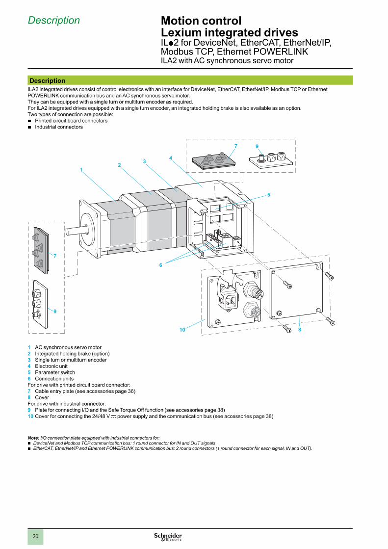
ILA2 integrated drives consist of control electronics with an interface for DeviceNet, EtherCAT, EtherNet/IP, Modbus TCP or Ethernet POWERLINK communication bus and an AC synchronous servo motor. They can be equipped with a single turn or multiturn encoder as required.For ILA2 integrated drives equipped with a single turn encoder, an integrated holding brake is also available as an option.Two types of connection are possible:
b
Printed circuit board connectors
bIndustrial connectors
7
9
12
34
7 9
5
810
6
1 AC synchronous servo motor2 Integrated holding brake (option)3 Single turn or multiturn encoder4 Electronic unit5 Parameter switch6 Connection unitsFor drive with printed circuit board connector:7 Cable entry plate (see accessories page 36)8 CoverFor drive with industrial connector:9 Plate for connecting I/O and the Safe Torque Off function (see accessories page 38)10 Cover for connecting the 24/48 V c power supply and the communication bus (see accessories page 38)
Note: I/O connection plate equipped with industrial connectors for:
bDeviceNet and Modbus TCP communication bus: 1 round connector for IN and OUT signals
b
EtherCAT, EtherNet/IP and Ethernet POWERLINK communication bus: 2 round connectors (1 round connector for each signal, IN and OUT).
2
1
3
4
5
6
7
8
9
10
2
1
3
4
5
6
7
8
9
10
1.0

21
References Example: I L A 2 D 5 7 1 P B 1 A 0
Motor typeA = AC synchronous servo motor
I L A 2 D 5 7 1 P B 1 A 0
Supply voltage2 = 24... 48 V
I L A 2 D 5 7 1 P B 1 A 0
Communication interfaceD = DeviceNetE = EtherCATK = EtherNet/IPP = Ethernet POWERLINKT = Modbus TCP
I L A 2 D 5 7 1 P B 1 A 0
Flange size57 = 57 mm
I L A 2 D 5 7 1 P B 1 A 0
Drive type (1)1 = ILA2p 5712 = ILA2p 572
I L A 2 D 5 7 1 P B 1 A 0
Winding type (1)P = medium rotation speedT = high rotation speed
I L A 2 D 5 7 1 P B 1 A 0
ConnectionB = printed circuit board connectorC = industrial connector
I L A 2 D 5 7 1 P B 1 A 0
Encoder type1 = single turn encoder(16,384 points/turn)2 = multiturn encoder (2)(16,384 points/turn x 4096 turns)
I L A 2 D 5 7 1 P B 1 A 0
Holding brakeA = without holding brakeF = with holding brake (2)
I L A 2 D 5 7 1 P B 1 A 0
Without gearbox0 = without gearbox
I L A 2 D 5 7 1 P B 1 A 0
(1) See the main characteristics and dimensions according to the type of drive in the table below:
Drive ILA2p 571 ILA2 p 572
Winding type T P T P
Nominal supplyvoltage
V c 24 48 24 48 24 48 24 48
Nominal speed of rotation
rpm 5000 7000 3200 5100 3000 5100 1600 3400
Peak stall torque
Nm 0.45 0.62 0.85 1.62
Continuous stall torque
Nm 0.31 0.44 0.57 0.78
Dimensions (overall in mm)
With single turn encoder
W x H x D
57.2 x 92.2 x 145.3 57.2 x 92.2 x 163.8
With multiturn encoder
W x H x D
57.2 x 92.2 x 189.3 57.2 x 92.2 x 207.8
With holding brake
W x H x D
57.2 x 92.2 x 190.8 57.2 x 92.2 x 209.3
(2) The holding brake and the multiturn encoder cannot be used together.
Note: See all the data (characteristics, dimensions) on our website www.schneider-electric.com.
References Motion controlLexium integrated drivesIL p 2 for DeviceNet, EtherCAT, EtherNet/IP, Modbus TCP, Ethernet POWERLINKILA2 with AC synchronous servo motor
ILA2 integrated drive with AC synchronous servo motor
2
1
3
4
5
6
7
8
9
10
2
1
3
4
5
6
7
8
9
10
22
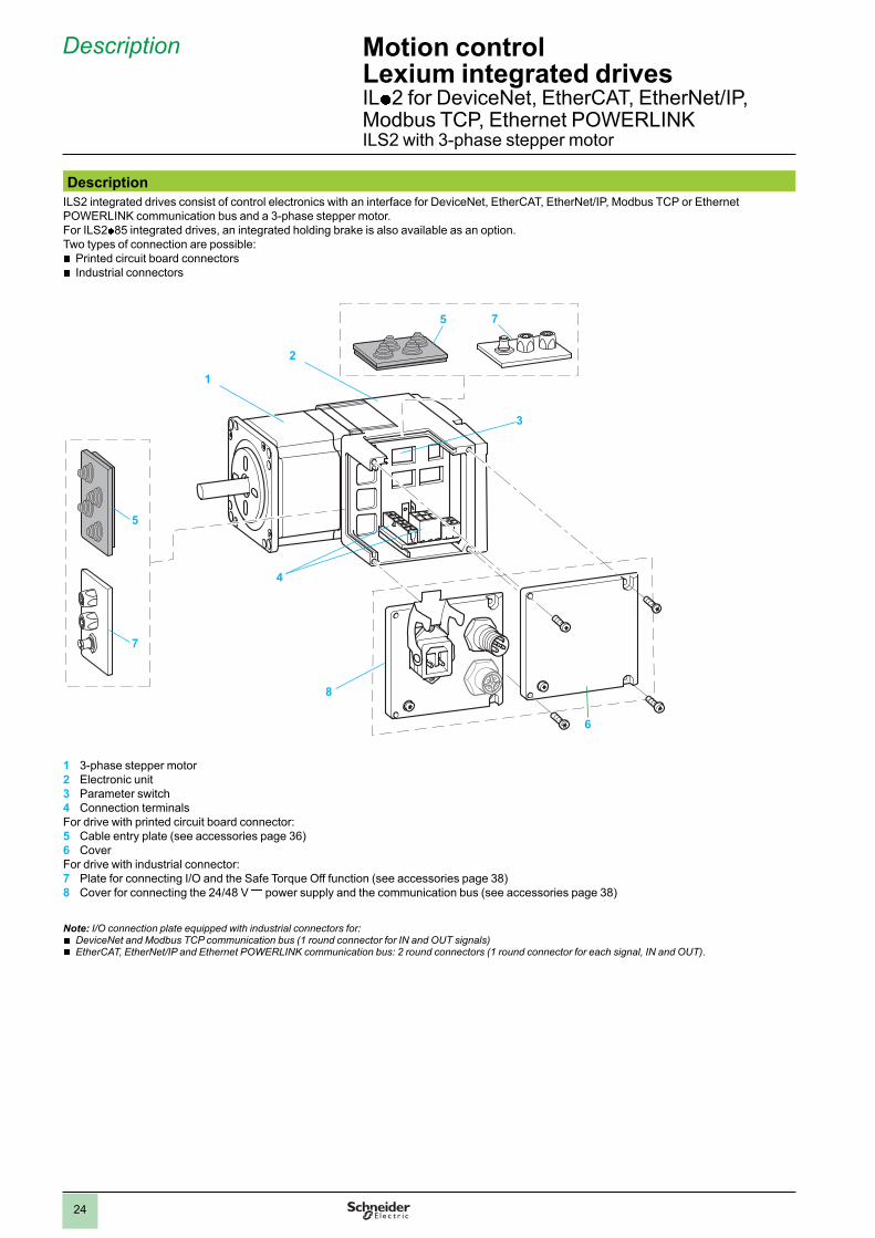
Description Motion controlLexium integrated drivesILp 2 for DeviceNet, EtherCAT, EtherNet/IP, Modbus TCP, Ethernet POWERLINKILE2 with DC brushless motor
Description
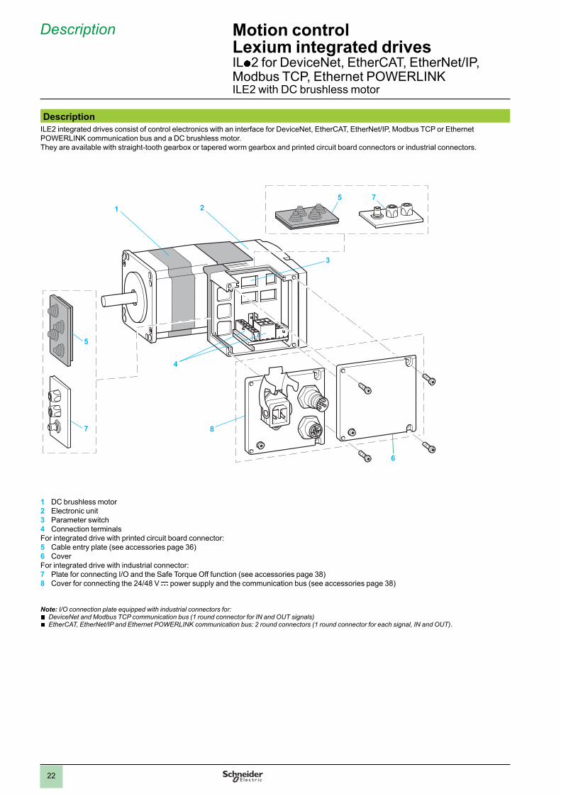
ILE2 integrated drives consist of control electronics with an interface for DeviceNet, EtherCAT, EtherNet/IP, Modbus TCP or Ethernet POWERLINK communication bus and a DC brushless motor. They are available with straight-tooth gearbox or tapered worm gearbox and printed circuit board connectors or industrial connectors.
5
7
1 2
5 7
3
6
8
4
1 DC brushless motor2 Electronic unit3 Parameter switch4 Connection terminalsFor integrated drive with printed circuit board connector:5 Cable entry plate (see accessories page 36)6 CoverFor integrated drive with industrial connector:7 Plate for connecting I/O and the Safe Torque Off function (see accessories page 38)8 Cover for connecting the 24/48 V c power supply and the communication bus (see accessories page 38)
Note: I/O connection plate equipped with industrial connectors for:
bDeviceNet and Modbus TCP communication bus (1 round connector for IN and OUT signals)
b
EtherCAT, EtherNet/IP and Ethernet POWERLINK communication bus: 2 round connectors (1 round connector for each signal, IN and OUT).
23
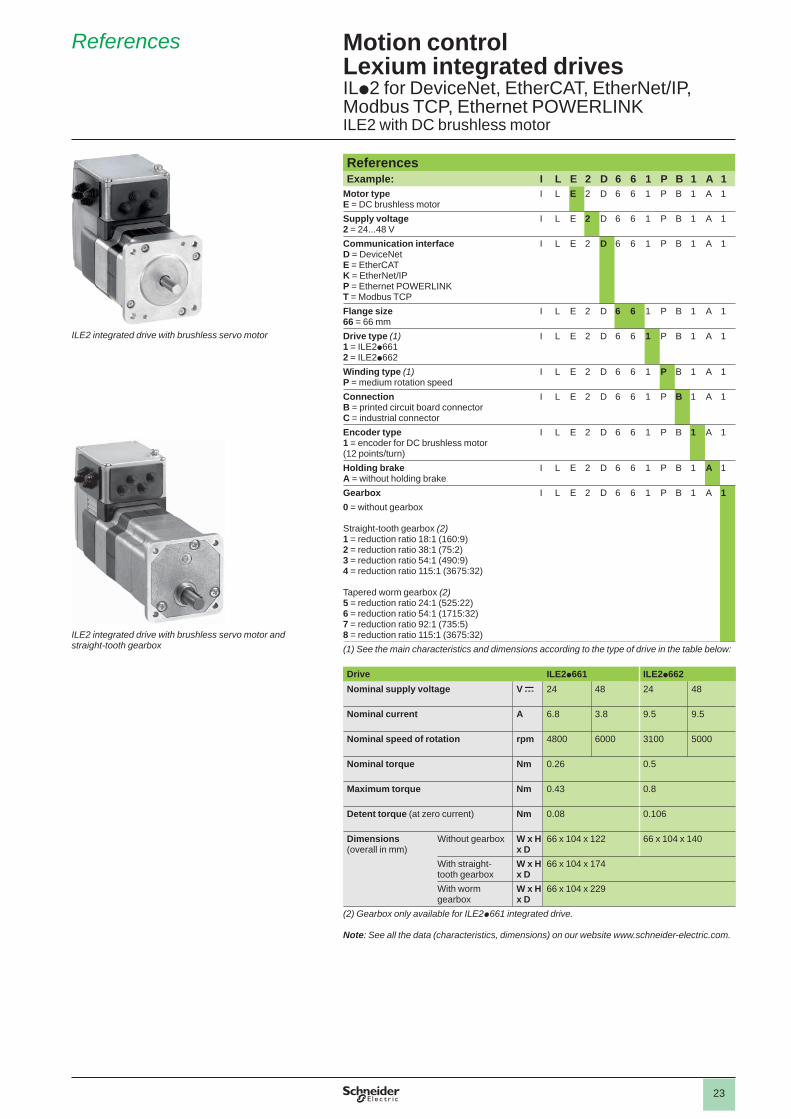
References Example: I L E 2 D 6 6 1 P B 1 A 1
Motor typeE = DC brushless motor
I L E 2 D 6 6 1 P B 1 A 1
Supply voltage2 = 24...48 V
I L E 2 D 6 6 1 P B 1 A 1
Communication interfaceD = DeviceNetE = EtherCATK = EtherNet/IPP = Ethernet POWERLINKT = Modbus TCP
I L E 2 D 6 6 1 P B 1 A 1
Flange size66 = 66 mm
I L E 2 D 6 6 1 P B 1 A 1
Drive type (1)1 = ILE2p6612 = ILE2p662
I L E 2 D 6 6 1 P B 1 A 1
Winding type (1)P = medium rotation speed
I L E 2 D 6 6 1 P B 1 A 1
ConnectionB = printed circuit board connectorC = industrial connector
I L E 2 D 6 6 1 P B 1 A 1
Encoder type 1 = encoder for DC brushless motor (12 points/turn)
I L E 2 D 6 6 1 P B 1 A 1
Holding brakeA = without holding brake
I L E 2 D 6 6 1 P B 1 A 1
Gearbox I L E 2 D 6 6 1 P B 1 A 10 = without gearbox
Straight-tooth gearbox (2)1 = reduction ratio 18:1 (160:9)2 = reduction ratio 38:1 (75:2)3 = reduction ratio 54:1 (490:9)4 = reduction ratio 115:1 (3675:32)
Tapered worm gearbox (2) 5 = reduction ratio 24:1 (525:22)6 = reduction ratio 54:1 (1715:32)7 = reduction ratio 92:1 (735:5)8 = reduction ratio 115:1 (3675:32)(1) See the main characteristics and dimensions according to the type of drive in the table below:
Drive ILE2p661 ILE2p662Nominal supply voltage V c 24 48 24 48
Nominal current A 6.8 3.8 9.5 9.5
Nominal speed of rotation rpm 4800 6000 3100 5000
Nominal torque Nm 0.26 0.5
Maximum torque Nm 0.43 0.8
Detent torque (at zero current) Nm 0.08 0.106
Dimensions (overall in mm)
Without gearbox W x H x D
66 x 104 x 122 66 x 104 x 140
With straight-tooth gearbox
W x H x D
66 x 104 x 174
With worm gearbox
W x H x D
66 x 104 x 229
(2) Gearbox only available for ILE2p661 integrated drive.
Note: See all the data (characteristics, dimensions) on our website www.schneider-electric.com.
References Motion controlLexium integrated drivesILp2 for DeviceNet, EtherCAT, EtherNet/IP, Modbus TCP, Ethernet POWERLINKILE2 with DC brushless motor
ILE2 integrated drive with brushless servo motor and straight-tooth gearbox
ILE2 integrated drive with brushless servo motor
24
Description
ILS2 integrated drives consist of control electronics with an interface for DeviceNet, EtherCAT, EtherNet/IP, Modbus TCP or Ethernet POWERLINK communication bus and a 3-phase stepper motor. For ILS2p 85 integrated drives, an integrated holding brake is also available as an option.Two types of connection are possible:
b
Printed circuit board connectors
bIndustrial connectors
1
2
5 7
3
6
8
4
5
7
1 3-phase stepper motor2 Electronic unit3 Parameter switch4 Connection terminalsFor drive with printed circuit board connector:5 Cable entry plate (see accessories page 36)6 CoverFor drive with industrial connector:7 Plate for connecting I/O and the Safe Torque Off function (see accessories page 38)8 Cover for connecting the 24/48 V c power supply and the communication bus (see accessories page 38)
Note: I/O connection plate equipped with industrial connectors for:
bDeviceNet and Modbus TCP communication bus (1 round connector for IN and OUT signals)
b
EtherCAT, EtherNet/IP and Ethernet POWERLINK communication bus: 2 round connectors (1 round connector for each signal, IN and OUT).
Description Motion controlLexium integrated drivesILp 2 for DeviceNet, EtherCAT, EtherNet/IP, Modbus TCP, Ethernet POWERLINKILS2 with 3-phase stepper motor
25
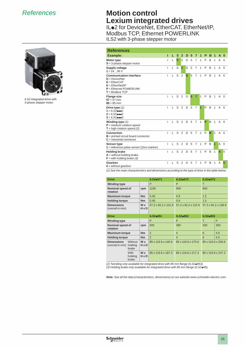
References Example: I L S 2 D 5 7 1 P B 1 A 0
Motor typeS = 3-phase stepper motor
I L S 2 D 5 7 1 P B 1 A 0
Supply voltage1 = 24…36 V
I L S 2 D 5 7 1 P B 1 A 0
Communication interfaceD = DeviceNetE = EtherCATK = EtherNet/IPP = Ethernet POWERLINKT = Modbus TCP
I L S 2 D 5 7 1 P B 1 A 0
Flange size57 = 57 mm85 = 85 mm
I L S 2 D 5 7 1 P B 1 A 0
Drive type (1)1 = ILS2ppp12 = ILS2ppp23 = ILS2ppp3
I L S 2 D 5 7 1 P B 1 A 0
Winding type (1)P = medium rotation speedT = high rotation speed (2)
I L S 2 D 5 7 1 P B 1 A 0
ConnectionB = printed circuit board connectorC = industrial connector
I L S 2 D 5 7 1 P B 1 A 0
Sensor type1 = reference pulse sensor (Zero marker)
I L S 2 D 5 7 1 P B 1 A 0
Holding brakeA = without holding brakeF = with holding brake (3)
I L S 2 D 5 7 1 P B 1 A 0
Gearbox0 = without gearbox
I L S 2 D 5 7 1 P B 1 A 0
(1) See the main characteristics and dimensions according to the type of drive in the table below:
Drive ILS2p571 ILS2p572 ILS2p573Winding type P P TNominal speed of rotation
rpm 1100 900 600
Maximum torque Nm 0.45 0.9 1.5Holding torque Nm 0.45 0.9 1.5Dimensions (overall in mm)
W x H x D
57.2 x 92.2 x 101.9 57.2 x 92.2 x 115.9 57.2 x 92.2 x 138.9
Drive ILS2p851 ILS2p852 ILS2p853Winding type P P T PNominal speed of rotation
rpm 600 380 200 300
Maximum torque Nm 2 4 6 4.5Holding torque Nm 2 4 6 4.5Dimensions (overall in mm)
Without holding brake
W x H x D
85 x 119.6 x 140.6 85 x 119.6 x 170.6 85 x 119.6 x 200.6
With holding brake
W x H x D
85 x 119.6 x 187.3 85 x 119.6 x 217.3 85 x 119.6 x 247.3
(2) Twinding only available for integrated drive with 85 mm fl ange (ILS2p853).(3) Holding brake only available for integrated drive with 85 mm fl ange (ILS2p85).
Note: See all the data (characteristics, dimensions) on our website www.schneider-electric.com.
References Motion controlLexium integrated drivesILp2 for DeviceNet, EtherCAT, EtherNet/IP, Modbus TCP, Ethernet POWERLINKILS2 with 3-phase stepper motor
ILS2 integrated drive with 3-phase stepper motor
26
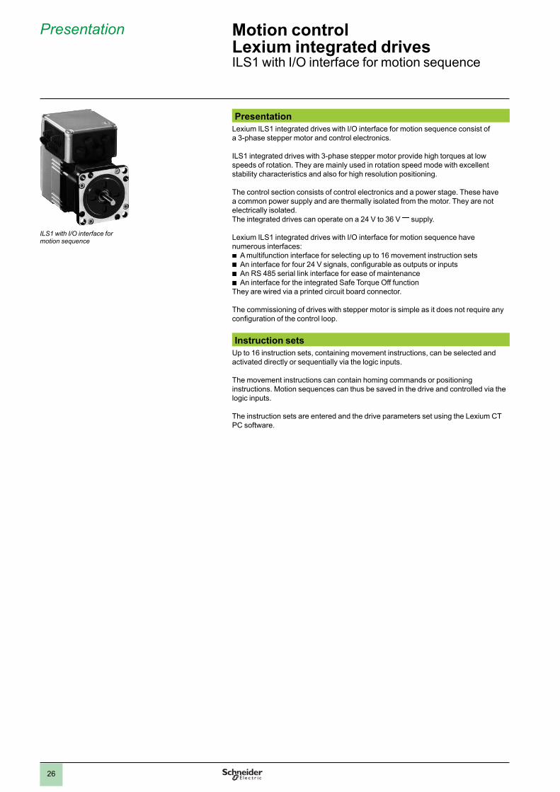
Presentation Motion controlLexium integrated drivesILS1 with I/O interface for motion sequence
Presentation
Lexium ILS1 integrated drives with I/O interface for motion sequence consist of a 3-phase stepper motor and control electronics.
ILS1 integrated drives with 3-phase stepper motor provide high torques at low speeds of rotation. They are mainly used in rotation speed mode with excellent stability characteristics and also for high resolution positioning.
The control section consists of control electronics and a power stage. These have a common power supply and are thermally isolated from the motor. They are not electrically isolated. The integrated drives can operate on a 24 V to 36 V c supply.
Lexium ILS1 integrated drives with I/O interface for motion sequence have numerous interfaces:
b
A multifunction interface for selecting up to 16 movement instruction sets
bAn interface for four 24 V signals, confi gurable as outputs or inputs
b
An RS 485 serial link interface for ease of maintenance
bAn interface for the integrated Safe Torque Off function
They are wired via a printed circuit board connector.
The commissioning of drives with stepper motor is simple as it does not require any confi guration of the control loop.
Instruction sets
Up to 16 instruction sets, containing movement instructions, can be selected and activated directly or sequentially via the logic inputs.
The movement instructions can contain homing commands or positioning instructions. Motion sequences can thus be saved in the drive and controlled via the logic inputs.
The instruction sets are entered and the drive parameters set using the Lexium CT PC software.
ILS1 with I/O interface for motion sequence

27
Interfaces
Multifunction interface
The multifunction interface is used to select and activate up to 16 instruction sets, containing movement instructions, via the logic inputs.
It is also possible to set the parameters of specifi c start functions.
RS 485 serial link interface
The RS 485 interface is used to connect an RS 485 serial link during confi guration, commissioning or maintenance.
It is used to connect the Lexium CT PC software with a direct link, via an RS 485/USB converter, to access the fault log, temperature control and various other functions.
Interface for 24 V signals
Four 24 V signals are available, confi gurable as inputs or outputs via the parameter switch.They can also be used to set the parameters of functions such as limit switch detection.
They can be used by the master controller.
The 24 V power for the outputs is provided internally via the integrated drive's power supply.
Interface for Safe Torque Off (Power Removal) safety function
The Safe Torque Off (Power Removal) safety function enables a category 0 or 1 stop to be performed in accordance with standard IEC/EN 60204-1 and/or prevents unintended motor operation in accordance with standard IEC/EN 61508 level SIL2, ISO 13849-1 performance level “d” (PL d) and IEC/EN 61800-5-2 (STO).
No additional power protection option is necessary. The Lexium ILS1 integrated drive can remain powered up, which reduces the system costs and the restart time.
The Safe Torque Off function is activated via two redundant 24 V input signals (active in OFF state).
Special technical features
b
High continuous stall torque
bGood speed stability characteristics
b
High encoder accuracy (0.018°)
bIntegrated holding brake available as an option for ILS1M85 integrated drive
b
Planetary gearbox available as an option
Presentation (continued) Motion controlLexium integrated drivesILS1 with I/O interface for motion sequence

28
Presentation (continued) Motion controlLexium integrated drivesILS1 with I/O interface for motion sequence
“Motion sequence” operating mode
Presentation
In “Motion sequence” operating mode, up to 16 movement instruction sets can be activated directly or sequentially via the logic input signals. The movement instructions can contain homing or positioning parameters. A motion sequence can thus be saved in the drive and controlled via the logic input signals.
The instruction sets are entered and the drive parameters set using the “Lexium CT” PC commissioning software.
Direct selection of movement instructions
Direct selection of movement instructions is used when a master controller is controlling the sequencing of the various instruction sets. The instruction set to be processed is selected and activated via the logic inputs.
Sequential selection of movement instructions
Sequential selection of movement instructions is used for processing simple motion sequences. Instruction sets are sequenced by entering a waiting time, a transition condition and the next instruction set.Example of a transition condition: rising edge on the START logic input.
A motion sequence can also be executed cyclically, with or without return to the initial position.
Processing status of a movement instruction
The status of the movement instruction is indicated via the Handshake output. It is also possible to indicate an internal processing status such as “Drive in motion” via an additional output signal.
Selection of the motion profi le
Speeds and accelerations are saved in motion profi les. The movement instruction set contains the list of motion profi les.
Other operating modes
Other operating modes can be set via the communication bus:
bManual (JOG)
b
Point-to-point
bHoming

29
Presentation (continued) Motion controlLexium integrated drivesILS1 with I/O interface for motion sequence
Integrated drive with printed circuit board connectors
Connection
Lexium ILS1 integrated drives are connected via printed circuit board connectors.
Printed circuit board connectors
Printed circuit board connectors are used to connect the multifunction interface, the RS 485 serial link, the interface for 24 V signals and the Safe Torque Off function, as well as the power supply.
The integrated drive is connected via two cable entry plates, to be ordered separately (see accessories page 36).
Compliance with international standards and certifi cations
The Lexium integrated drives offer has been developed in accordance with strict international standards and recommendations for variable speed electrical power drive products, in particular IEC/EN 61800-3 (immunity to disturbance related to high frequency signals transmitted along cables) and IEC/EN 50178 (vibration resistance).
Compliance with electromagnetic compatibility requirements has been incorporated in the design of the integrated drive. The entire range conforms to international standard IEC/EN 61800-3:2001, environment 2.
The integrated drives carry the e
mark in accordance with the European machinery directive (98/37/EEC) and the European EMC directive (2004/108/EEC).
The entire range is certifi ed (United States and Canada). It is also TÜV certifi ed in accordance with the safety standards for medical devices and equipment. This certifi cation covers:
b
Functional safety of electrical/electronic/programmable electronic safety-related systems (IEC 61508: 2000; SIL 2)
b
Safety of machinery – functional safety of safety-related electrical, electronic and programmable electronic control systems (IEC 62061: 2005; SILcl2)
b
Safety of machinery – safety-related parts of electronic control systems – part 1: General principles for design (ISO 13849-1: 2006; PL d (category 3))

30
Description
Lexium ILS1 integrated drives with I/O interface for motion sequence consist of control electronics and a 3-phase stepper motor. They are available with printed circuit board connectors. For ILS1M85 drives, an integrated holding brake is available as an option.
1 3-phase stepper motor2 Electronic unit3 Cable entry plate (see accessories page 36)4 Cover 5 Connection terminals
Description Motion controlLexium integrated drivesILS1 with I/O interface for motion sequenceILS1 with 3-phase stepper motor
3
2
5
1
3
4

31
References Motion controlLexium integrated drivesILS1 with I/O interface for motion sequenceILS1 with 3-phase stepper motor
ReferencesExample: I L S 1 M 5 7 1 P B 1 A 0
Motor typeS = 3-phase stepper motor
I L S 1 M 5 7 1 P B 1 A 0
Supply voltage1 = 24…36 V
I L S 1 M 5 7 1 P B 1 A 0
InterfaceM = I/O interface for motion sequence
I L S 1 M 5 7 1 P B 1 A 0
Flange size57 = 57 mm85 = 85 mm
I L S 1 M 5 7 1 P B 1 A 0
Drive type (1)1 = ILS1Mp p 12 = ILS1Mp p 23 = ILS1Mp p 3
I L S 1 M 5 7 1 P B 1 A 0
Winding type (1)P = medium rotation speedT = high rotation speed (2)
I L S 1 M 5 7 1 P B 1 A 0
ConnectionB = printed circuit board connector
I L S 1 M 5 7 1 P B 1 A 0
Sensor type1 = reference pulse sensor (Zero marker)
I L S 1 M 5 7 1 P B 1 A 0
Holding brakeA = without holding brakeF = with holding brake (3)
I L S 1 M 5 7 1 P B 1 A 0
Gearbox0 = without gearbox
I L S 1 M 5 7 1 P B 1 A 0
(1) See the main characteristics and dimensions according to the type of drive in the table below:
Drive ILS1M571 ILS1M572 ILS1M573
Winding type P P P
Nominal speed of rotation
rpm 1000 600 450
Maximum torque Nm 0.45 0.9 1.5
Holding torque Nm 0.51 1.02 1.7
Dimensions (overall in mm)
W x H x D
57.2 x 92.2 x 101.9 57.2 x 92.2 x 115.9 57.2 x 92.2 x 138.9
Drive ILS1M851 ILS1M852 ILS1M853
Winding type P P P T
Nominal speed of rotation
rpm 450 200 120 300
Maximum torque Nm 2 4 6 4.5
Holding torque Nm 2 4 6 4.5
Dimensions (overall in mm)
Without holding brake
W x H x D
85 x 119.6 x 140.6 85 x 119.6 x 170.6 85 x 119.6 x 200.6
With holding brake
W x H x D
85 x 119.6 x 187.3 85 x 119.6 x 217.3 85 x 119.6 x 247.3
(2) Twinding only available for integrated drive with 85 mm fl ange (ILS1M853).(3) Holding brake only available for integrated drive with 85 mm fl ange (ILS1M85).
Note: See all the data (characteristics, dimensions) on our website www.schneider-electric.com.
ILS1 integrated drive with I/O interface for motion sequence

32
Presentation Motion controlLexium integrated drivesILS1 with pulse/direction (P/D) interface
ILS1 with pulse/direction (P/D) interface
Presentation
ILS1 integrated drives consist of a 3-phase stepper motor and control electronics with pulse/direction (P/D) interface. The pulse/direction (P/D) signals from a master controller, for example a Lexium Controller, or the A/B signals from an encoder are converted directly into a movement.
ILS1 integrated drives with 3-phase stepper motor provide high torques at low speeds of rotation. They are mainly used in rotation speed mode with excellent speed stability characteristics and also for high resolution positioning.
The control section consists of control electronics and a power stage which have a common power supply and are thermally insulated from the motor. They are not electrically isolated. ILS1 integrated drives can operate on a 24 V to 36 V c supply.
ILS1 integrated drives control the stepper motor according to a reference value. This reference value is sent to the multifunction interface by a master controller or an external master encoder.The number of steps per turn is set via the parameter switch.
ILS1 integrated drives with pulse/direction (P/D) interface have numerous interfaces:
bA multifunction interface
b
An interface for four 24 V signals
bAn RS 485 serial link interface
b
An interface for the integrated Safe Torque Off function They are wired via a printed circuit board connector.
The commissioning of ILS1 drives with stepper motor is simple as it does not require any confi guration of the control loop.
Interfaces
Multifunction interface
The multifunction interface takes one of the following signals, depending on the integrated drive model:
b
24 V signals separated by optical coupler (ILS1U)
b5 V signals separated by optical coupler (ILS1V)
b
5 V differential signals without electrical isolation (ILS1W)
The reference values are sent via two signals, either as pulse/direction (P/D) signals, or as type A/B encoder signals. The other signals have the following functions:
b
“Activation/locking of the power stage and activation/locking of the indexing pulse”
b“Setting the number of steps/setting the motor phase current”
RS 485 serial link interface
The RS 485 signal interface is used to connect an RS 485 serial link during confi guration, commissioning or maintenance.
It is used to connect the Lexium CT PC software with a direct link, via an RS 485/RS 232 or RS 485/USB converter, to access the fault log, temperature control and various other functions.
Interface for 24 V signals
Two input signals and two output signals are available. The input signals have the following functions:
b
“Setting the number of steps”
b“Activation and locking of the power stage/activation and locking of the indexing pulse”
The output signals have the following functions:
b“Drive ready”
b
“Display a fault/indexing pulse”The 24 V power for the outputs is provided internally via the integrated drive's power supply.

33
Interfaces (continued)Interface for Safe Torque Off (Power Removal) safety function
The Safe Torque Off (Power Removal) safety function enables a category 0 or 1 stop to be performed in accordance with standard IEC/EN 60204-1 and/or prevents unintended motor operation in accordance with standard IEC/EN 61508 level SIL2, ISO 13849-1 performance level “d” (PL d) and IEC/EN 61800-5-2 (STO).
No additional power protection option is necessary. The Lexium ILS1 integrated drive can remain powered up, which reduces the system costs and the restart time.
The Safe Torque Off function is activated via two redundant 24 V input signals (active in OFF state).
Special technical features b High continuous stall torque b Good speed stability characteristics b High encoder accuracy (0.018°) b Integrated holding brake available as an option for the ILS1p85 integrated drive b Planetary gearbox available as an option
ConnectionLexium ILS integrated drives are connected via printed circuit board connectors.
Printed circuit board connectorsPrinted circuit board connectors are used to connect the multifunction interface, the RS 485 serial link, the interface for 24 V signals and the Safe Torque Off function, as well as the power supply.
The integrated drive is connected via two plates for cable entry plates, to be ordered separately (see accessories page 36).
Main functionsConfi guration by parameter switch
The following functions can be set on ILS1 integrated drives via the parameter switch: b Number of steps b Motor phase current b Reduction of motor phase current b Input signal functions: v Transmission of the reference value via pulse/direction (PULSE/DIR) or encoder
(A/B) signals v Activation/locking of the power stage (ENABLE/GATE input signal) v Activation/locking of the indexing pulse (ENABLE/GATE input signal) v Modulation of the motor phase current via a PWM signal (PWM/STEP2_INV
input signal) v Increase/decrease the number of steps by a factor of 10 (PWM/STEP2_INV input
signal) b Output signal functions: v Display a fault (FAULT/INDEXPULSE output signal) v Indexing pulse signal (FAULT/INDEXPULSE output signal) v “Drive ready” signal (ACTIVE output signal) b Blocking detection b Activation of the RS 485 line terminator b Activation/deactivation of the Safe Torque Off function
Presentation (continued) Motion controlLexium integrated drivesILS1 with pulse/direction (P/D) interface
Integrated drive with printed circuit board connectors
34
Description Motion controlLexium integrated drivesILS1 with pulse/direction (P/D) interfaceILS1 with 3-phase stepper motor
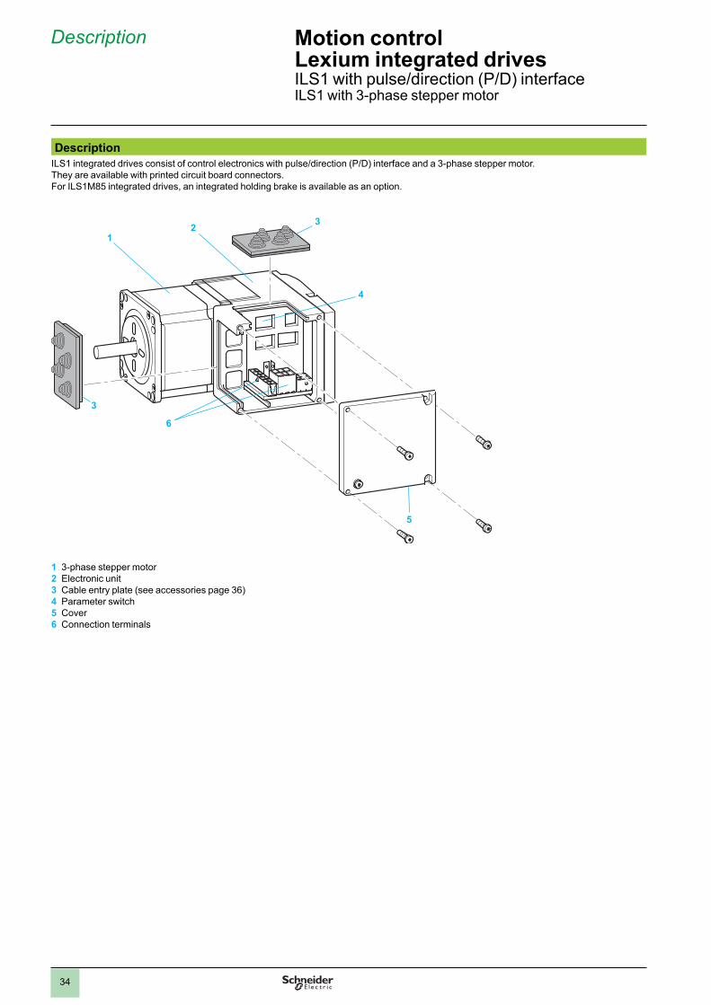
Description
ILS1 integrated drives consist of control electronics with pulse/direction (P/D) interface and a 3-phase stepper motor. They are available with printed circuit board connectors.For ILS1M85 integrated drives, an integrated holding brake is available as an option.
3
12
3
4
5
6
1 3-phase stepper motor2 Electronic unit3 Cable entry plate (see accessories page 36)4 Parameter switch5 Cover6 Connection terminals

35
References Motion controlLexium integrated drivesILS1 with pulse/direction (P/D) interfaceILS1 with 3-phase stepper motor
ReferencesExample: I L S 1 U 5 7 1 P B 1 A 0
Motor typeS = 3-phase stepper motor
I L S 1 U 5 7 1 P B 1 A 0
Supply voltage1 = 24…36 V
I L S 1 U 5 7 1 P B 1 A 0
InterfaceU = 24 V pulse/direction signals, separated by optical couplerV = 5 V pulse/direction signals, separated by optical couplerW = 5 V pulse/direction signals, RS 422
I L S 1 U 5 7 1 P B 1 A 0
Flange size57 = 57 mm85 = 85 mm
I L S 1 U 5 7 1 P B 1 A 0
Drive type (1)1 = ILS1p p p 12 = ILS1p p p 23 = ILS1p p p 3
I L S 1 U 5 7 1 P B 1 A 0
Winding typeP = medium rotation speedT = high rotation speed (2)
I L S 1 U 5 7 1 P B 1 A 0
ConnectionB = printed circuit board connector
I L S 1 U 5 7 1 P B 1 A 0
Sensor type1 = reference pulse sensor (Zero marker)
I L S 1 U 5 7 1 P B 1 A 0
Holding brakeA = without holding brakeF = with holding brake (3)
I L S 1 U 5 7 1 P B 1 A 0
Gearbox0 = without gearbox
I L S 1 U 5 7 1 P B 1 A 0
(1) See the main characteristics and dimensions according to the type of drive in the table below:
Drive ILS1p 571 ILS1 p 572 ILS1p 573
Winding type P P P
Nominal speed of rotation
rpm 1000 600 450
Maximum torque Nm 0.45 0.9 1.5
Holding torque Nm 0.51 1.02 1.7
Dimensions (overall in mm)
W x H x D
57.2 x 92.2 x 101.9 57.2 x 92.2 x 115.9 57.2 x 92.2 x 138.9
Drive ILS1p 851 ILS1 p 852 ILS1p 853
Winding type P P P T
Nominal speed of rotation
rpm 450 200 120 300
Maximum torque Nm 2 4 6 4.5
Holding torque Nm 2 4 6 4.5
Dimensions (overall in mm)
Without holding brake
W x H x D
85 x 119.6 x 140.6 85 x 119.6 x 170.6 85 x 119.6 x 200.6
With holding brake
W x H x D
85 x 119.6 x 187.3 85 x 119.6 x 217.3 85 x 119.6 x 247.3
(2) Twinding only available for integrated drive with 85 mm fl ange (ILS1p 853).(3) Holding brake only available for integrated drive with 85 mm fl ange (ILS1p 85).
Note: See all the data (characteristics, dimensions) on our website www.schneider-electric.com.
ILS1 integrated drive with pulse/direction interface
36
References Motion controlLexium integrated drivesAccessories for ILA, ILE and ILS integrated drives
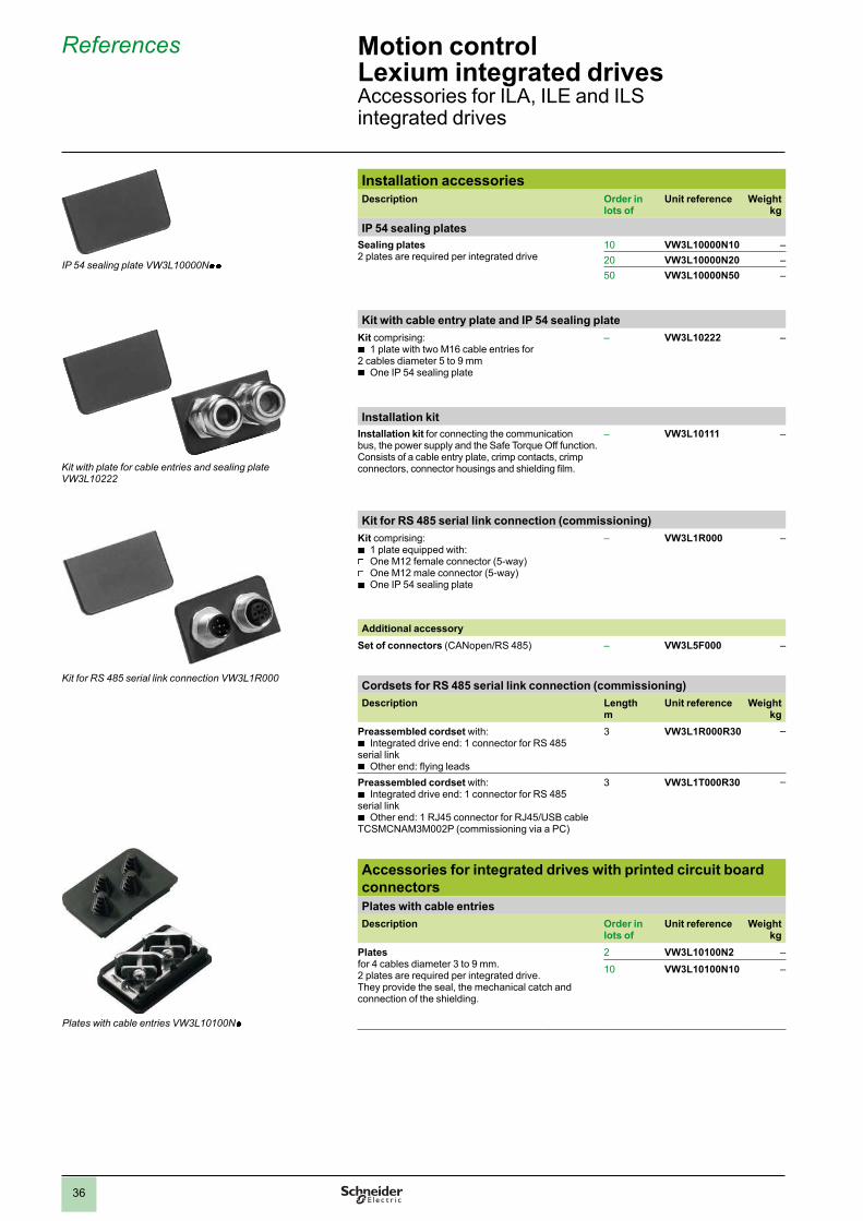
Installation accessoriesDescription Order in
lots ofUnit reference Weight
kg
IP 54 sealing plates
Sealing plates2 plates are required per integrated drive
10 VW3L10000N10 –
20 VW3L10000N20 –
50 VW3L10000N50 –
Kit with cable entry plate and IP 54 sealing plate
Kit comprising:
b1 plate with two M16 cable entries for
2 cables diameter 5 to 9 mm
bOne IP 54 sealing plate
– VW3L10222 –
Installation kit
Installation kit for connecting the communication bus, the power supply and the Safe Torque Off function.Consists of a cable entry plate, crimp contacts, crimp connectors, connector housings and shielding fi lm.
– VW3L10111 –
Kit for RS 485 serial link connection (commissioning)
Kit comprising:
b1 plate equipped with:
v
One M12 female connector (5-way)
vOne M12 male connector (5-way)
b
One IP 54 sealing plate
– VW3L1R000 –
Additional accessory
Set of connectors (CANopen/RS 485) – VW3L5F000 –
Cordsets for RS 485 serial link connection (commissioning)
Description Length m
Unit reference Weightkg
Preassembled cordset with:
bIntegrated drive end: 1 connector for RS 485
serial link
bOther end: fl ying leads
3 VW3L1R000R30 –
Preassembled cordset with:
bIntegrated drive end: 1 connector for RS 485
serial link
bOther end: 1 RJ45 connector for RJ45/USB cable
TCSMCNAM3M002P (commissioning via a PC)
3 VW3L1T000R30 –
Accessories for integrated drives with printed circuit board
connectors
Plates with cable entries
Description Order inlots of
Unit reference Weightkg
Plates for 4 cables diameter 3 to 9 mm. 2 plates are required per integrated drive. They provide the seal, the mechanical catch and connection of the shielding.
2 VW3L10100N2 –
10 VW3L10100N10 –
Plates with cable entries VW3L10100Np
Kit with plate for cable entries and sealing plateVW3L10222
IP 54 sealing plate VW3L10000Np p
Kit for RS 485 serial link connection VW3L1R000
2
1
3
4
5
6
7
8
9
10
2
1
3
4
5
6
7
8
9
10
1.0

37
Accessories for integrated drives with printed circuit board
connectors (continued)
Cordsets for Safe Torque Off signals
Description For use with Length m
Unit reference Weightkg
Preassembled cordsets with:
bIntegrated drive end:
1 connector for Safe Torque Off function
b
Other end: fl ying leads
– 3 VW3L20010R30 –
– 5 VW3L20010R50 –
– 10 VW3L20010R100 –
– 15 VW3L20010R150 –
20 VW3L20010R200 –
Cordsets for communication bus interfaces (CANopen, PROFIBUS DP,
RS 485, DeviceNet) and power supply
Preassembled cordsets with:
bIntegrated drive end: cable
entry and mechanical catch.For power supply and communication bus.
b
Other end: fl ying leads for power supply and 9-way SUB-D connector for communication bus.
CANopen 3 VW3L2F001R30 –
PROFIBUS DP 3 VW3L2B001R30 –
RS 485 3 VW3L2R001R30 –
DeviceNet 3 VW3L2D001R30 –
Cordsets for communication bus interfaces (EtherCAT, EtherNet/IP,
Modbus TCP, Ethernet POWERLINK) and power supply
Preassembled cordsets with:
bIntegrated drive end: cable
entry and mechanical catch.For power supply and communication bus.
b
Other end:
vfl ying leads for power supply
v
RJ45 connector for communication bus
EtherCAT 3 VW3L2E001R30 –
EtherNet/IP 3 VW3L2K001R30 –
Modbus TCP 3 VW3L2T001R30 –
EtherNet POWERLINK
3 VW3L2P001R30 –
Cordsets for ILS1 integrated drives with I/O interface for motion
sequence
Preassembled cordsets with:
bIntegrated drive end: plate with cable entry and
mechanical catch for control via data sets.For power supply and I/O signals.
b
Other end: fl ying leads
3 VW3L2M001R30 –
5 VW3L2M001R50 –
10 VW3L2M001R100 –
15 VW3L2M001R150 –
20 VW3L2M001R200 –
Cordsets for ILS1 integrated drives with I/O interface for motion sequence
and plate for I/O signals and Safe Torque Off signals
Preassembled cordsets with:
bIntegrated drive end: plate with cable entry and
mechanical catch for control via data sets.For power supply and I/O signals.
b
Other end: fl ying leads
Additional plate equipped with:
bTwo connectors for I/O signals
b
One M8 connector for Safe Torque Off signals
3 VW3L2M211R30 –
5 VW3L2M211R50 –
10 VW3L2M211R100 –
15 VW3L2M211R150 –
20 VW3L2M211R200 –
Cordsets for ILS1 integrated drives with pulse/direction (P/D) interface
Preassembled cordsets with:
bIntegrated drive end: plate with cable entry and
mechanical catch.For power supply and pulse/direction (P/D) or A/B encoder signals.
b
Other end: fl ying leads
3 VW3L2U001R30 –
5 VW3L2U001R50 –
10 VW3L2U001R100 –
15 VW3L2U001R150 –
20 VW3L2U001R200 –
References (continued) Motion controlLexium integrated drivesAccessories for ILA, ILE and ILS integrated drives
Cordset for ILS1 integrated drive with pulse/direction interface VW3L2U001Rp p
Cordset for interfaces for communication bus and power supply VW3L2p 001R30
Cordset for ILS1 integrated drives with I/O interface and plate for I/O and safety signals VW3L2M211Rp p
Cordset for ILS1 integrated drives with I/O interface VW3L2M001Rp p
2
1
3
4
5
6
7
8
9
10
2
1
3
4
5
6
7
8
9
10

38
References (continued) Motion controlLexium integrated drivesAccessories for ILA, ILE and ILS integrated drives
Accessories for integrated drives with industrial connectorsDescription Reference Weight
kg
Cover for connecting the power supply and the communication bus
Cover for connecting the power supply and the communication bus:
PROFIBUS DP VW3L1B001N01 –
DeviceNet VW3L1D001N01 –
EtherNet/IP, EtherCAT, EtherNet POWERLINK VW3L1E001N01 –
CANopen VW3L1F001N01 –
Modbus TCP VW3L1T001N01 –
RS 485 VW3L1R001N01 –
Kit for I/O signals
Kit comprising:
bOne plate equipped with three M8 female connectors (3-way)
for I/O signals
bOne IP 54 sealing plate
VW3L40300 –
Additional accessory
Set of 3 connectors for connecting I/O VW3L50300 –
Kit for Safe Torque Off signals
Kit comprising:
bOne plate equipped with one male and one female M8
connector (4-way) for two Safe Torque Off signals
bOne IP 54 sealing plate
VW3L40020 –
Additional accessory
Cordsets (M8x4) for Safe Torque Off signals (see below for full references)
VW3L30010Rp p p –
Kit for I/O signals and Safe Torque Off signals
Kit comprising:
bOne plate equipped with:
v
Two M8 female connectors (3-way) for I/O signals
vOne M8 male connector (4-way) for Safe Torque Off signals
b
One IP 54 sealing plate
VW3L40210 –
Kit comprising:
bOne plate equipped with:
v
Two M8 female connectors (3-way) for I/O signals
vOne M8 male connector (4-way) for Safe Torque Off signals
b
One plate equipped with:
vTwo M8 female connectors (3-way) for I/O signals
v
One M8 female connector (4-way) for Safe Torque Off signals
VW3L40420 –
Additional accessories
Set of 2 connectors for I/O VW3L50200 –
Connector for Safe Torque Off signals VW3L50010 –
Cordset (M8x4) for Safe Torque Off signals (see below for full references)
VW3L30010Rp p p –
Cordsets for Safe Torque Off signals
Description Lengthm
Reference Weightkg
Cordsets equipped with one M8 female connector (4-way) for connecting Safe Torque Off signals
3 VW3L30010R30 –
5 VW3L30010R50 –
10 VW3L30010R100 –
15 VW3L30010R150 –
20 VW3L30010R200 –
Kit for I/O signals VW3L40300
Kit for I/O signals and Safe Torque Off signals VW3L40210
Kit for I/O signals and Safe Torque Off signals VW3L40420
Cordsets for Safe Torque Off signals VW3L30010Rp p
2
1
3
4
5
6
7
8
9
10
2
1
3
4
5
6
7
8
9
10

39
Accessories for integrated drives with industrial connectors
(continued)
Description Length m
Reference Weight kg
Power cordsets
Preassembled cordsets with:
bIntegrated drive end: 1 connector for power
supply
bOther end: fl ying leads
DESINA compliant
3 VW3L30001R30 –
5 VW3L30001R50 –
10 VW3L30001R100 –
15 VW3L30001R150 –
20 VW3L30001R200 –
Connector for Safe Torque Off signals
Connector, M8 round (4-way)for creating cordsets for Safe Torque Off signals
VW3L50010 –
Set of 2 connectors for I/O signals
Set consisting of:
bTwo M8 round connectors (3-way)
VW3L50200 –
Set of 3 connectors for I/O signals
Set consisting of:
bThree M8 round connectors (3-way)
VW3L50300 –
Set of CANopen/RS 485 connectors for ILp 1 integrated drives
Set consisting of:
bOne M12 round male connector (A-coded)
b
One M12 round female connector (A-coded)
bOne M12 blanking plug
VW3L5F000 –
Set of PROFIBUS DP connectors for ILp 1 integrated drives
Set consisting of:
bOne M12 round male connector (B-coded)
b
One M12 round female connector (B-coded)
bOne M12 blanking plug
VW3L5B000 –
Set of EtherCAT connectors
Set consisting of:
bTwo M12 round male connectors (4-way), (D-coded)
b
One M12 blanking plug
VW3L5E000 –
Set of EtherNet/IP connectors
Set consisting of:
bTwo M12 round male connectors (4-way), (D-coded)
b
One M12 blanking plug
VW3L5K000 –
Set of Ethernet POWERLINK connectors
Set consisting of:
bTwo M12 round male connectors (4-way), (D-coded)
b
One M12 blanking plug
VW3L5P000 –
DeviceNet connector
Female connector, M12 DeviceNet (5-way), (A-coded) VW3L5D000 –
Modbus TCP connector
Female connector, M12 Modbus TCP (4-way), (D-coded)
VW3L5T000 –
References (continued) Motion controlLexium integrated drivesAccessories for ILA, ILE and ILS integrated drives
Set of connectors for I/O signals VW3L50200
Connector for Safe Torque Off signals VW3L50010
Set of connectors for EtherCAT bus VW3L5E000
Power cordsets VW3L30001Rp p
Connector for DeviceNet bus VW3L5D000
2
1
3
4
5
6
7
8
9
10
2
1
3
4
5
6
7
8
9
10
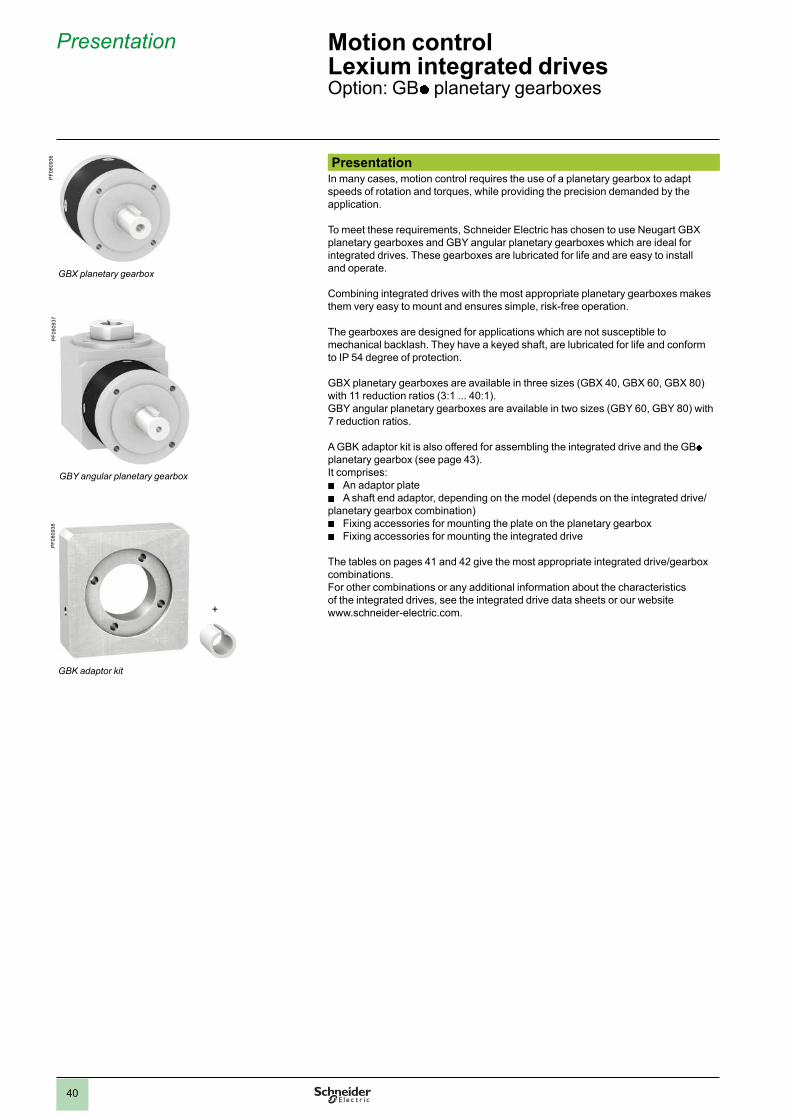
40
Presentation Motion controlLexium integrated drivesOption: GB p planetary gearboxes
PresentationIn many cases, motion control requires the use of a planetary gearbox to adapt speeds of rotation and torques, while providing the precision demanded by the application.
To meet these requirements, Schneider Electric has chosen to use Neugart GBX planetary gearboxes and GBY angular planetary gearboxes which are ideal for integrated drives. These gearboxes are lubricated for life and are easy to install and operate.
Combining integrated drives with the most appropriate planetary gearboxes makes them very easy to mount and ensures simple, risk-free operation.
The gearboxes are designed for applications which are not susceptible to mechanical backlash. They have a keyed shaft, are lubricated for life and conform to IP 54 degree of protection.
GBX planetary gearboxes are available in three sizes (GBX 40, GBX 60, GBX 80) with 11 reduction ratios (3:1 ... 40:1).GBY angular planetary gearboxes are available in two sizes (GBY 60, GBY 80) with 7 reduction ratios.
A GBK adaptor kit is also offered for assembling the integrated drive and the GBp planetary gearbox (see page 43).It comprises:
b An adaptor plate b A shaft end adaptor, depending on the model (depends on the integrated drive/
planetary gearbox combination) b Fixing accessories for mounting the plate on the planetary gearbox b Fixing accessories for mounting the integrated drive
The tables on pages 41 and 42 give the most appropriate integrated drive/gearbox combinations. For other combinations or any additional information about the characteristics of the integrated drives, see the integrated drive data sheets or our website www.schneider-electric.com.
GBY angular planetary gearbox
PF
080937
PF
080936
GBX planetary gearbox
PF
080938
GBK adaptor kit
+
2
1
3
4
5
6
7
8
9
10
2
1
3
4
5
6
7
8
9
10
1.0

41
ReferencesSize Reduction ratio Reference (1) Weight
kg
GBX 40 3:1, 5:1 and 8:1 GBX 040 p p p K 0.350
GBX 60 3:1, 4:1, 5:1 and 8:1 GBX 060 p p p K 0.900
9:1, 12:1, 15:1,16:1, 20:1, 25:1 and 40:1
GBX 060 p p p K 1.100
GBX 80 3:1, 4:1, 5:1 and 8:1 GBX 080 p p p K 2.100
9:1, 12:1, 15:1, 16:1, 20:1 and 25:1 GBX 080 p p p K 2.600
(1) To order a GBY angular planetary gearbox, complete each of the above references as follows:
GBX p p p p p p K
Size Housing diameter 40 mm 040
60 mm 060
80 mm 080
Reduction ratio 3:1 003
5:1 005
8:1 008
9:1 009
12:1 012
15:1 015
16:1 016
20:1 020
25:1 025
40:1 040
Mounting with GBK adaptor kit(see page 43)
K
Integrated drive/GBX planetary gearbox combinationsReduction ratios from 3:1 to 40:1
Type of integrated drive
Reduction ratio
3:1 4:1 5:1 8:1 9:1 12:1 15:1 16:1 20:1 25:1 40:1
ILA1p 571T GBX 60 GBX 60 GBX 60 GBX 60 GBX 60 GBX 60 GBX 60 GBX 60 GBX 60 GBX 60 GBX 60
ILA1p 571P GBX 60 GBX 60 GBX 60 GBX 60 GBX 60 GBX 60 GBX 60 GBX 60 GBX 60 GBX 60 GBX 60
ILA1p 572T GBX 60 GBX 60 GBX 60 GBX 60 GBX 60 GBX 60 GBX 60 GBX 60 GBX 60 GBX 60 GBX 60
ILA1p 572P GBX 60 GBX 60 GBX 60 GBX 60 GBX 60 GBX 60 GBX 60 GBX 60 GBX 60 GBX 60 GBX 60
ILA2p 571T GBX 60 GBX 60 GBX 60 GBX 60 GBX 60 GBX 60 GBX 60 GBX 60 GBX 60 GBX 60 GBX 60
ILA2p 571P GBX 60 GBX 60 GBX 60 GBX 60 GBX 60 GBX 60 GBX 60 GBX 60 GBX 60 GBX 60 GBX 60
ILA2p 572T GBX 60 GBX 60 GBX 60 GBX 60 GBX 60 GBX 60 GBX 60 GBX 60 GBX 60 GBX 60 GBX 60
ILA2p 572P GBX 60 GBX 60 GBX 60 GBX 60 GBX 60 GBX 60 GBX 60 GBX 60 GBX 60 GBX 60 GBX 60
ILE1p 661P GBX 40 – GBX 40 GBX 40 GBX 60 GBX 60 GBX 60 GBX 60 GBX 60 GBX 60 GBX 60
ILE2p 661P GBX 40 – GBX 40 GBX 40 GBX 60 GBX 60 GBX 60 GBX 60 GBX 60 GBX 60 GBX 60
ILE2p 662P GBX 40 – GBX 40 GBX 40 GBX 60 GBX 60 GBX 60 GBX 60 GBX 60 GBX 60 GBX 60
ILS1p 571P GBX 60 GBX 60 GBX 60 GBX 60 GBX 60 GBX 60 GBX 60 GBX 60 GBX 60 GBX 60 GBX 60
ILS1p 572P GBX 60 GBX 60 GBX 60 GBX 60 GBX 60 GBX 60 GBX 60 GBX 60 GBX 60 GBX 60 GBX 60
ILS1p 573P GBX 60 GBX 60 GBX 60 GBX 60 GBX 60 GBX 60 GBX 60 GBX 60 GBX 60 GBX 60 GBX 60
ILS1p 851P GBX 80 GBX 80 GBX 80 GBX 80 GBX 80 GBX 80 GBX 80 GBX 80 GBX 80 GBX 80 –
ILS1p 852P GBX 80 GBX 80 GBX 80 GBX 80 GBX 80 GBX 80 GBX 80 GBX 80 GBX 80 GBX 80 –
ILS1p 853P GBX 80 GBX 80 GBX 80 GBX 80 GBX 80 GBX 80 GBX 80 GBX 80 GBX 80 GBX 80 –
ILS1p 853T GBX 80 GBX 80 GBX 80 GBX 80 GBX 80 GBX 80 GBX 80 GBX 80 GBX 80 GBX 80 –
ILS2p 571P GBX 60 GBX 60 GBX 60 GBX 60 GBX 60 GBX 60 GBX 60 GBX 60 GBX 60 GBX 60 GBX 60
ILS2p 572P GBX 60 GBX 60 GBX 60 GBX 60 GBX 60 GBX 60 GBX 60 GBX 60 GBX 60 GBX 60 GBX 60
ILS2p 573P GBX 60 GBX 60 GBX 60 GBX 60 GBX 60 GBX 60 GBX 60 GBX 60 GBX 60 GBX 60 GBX 60
ILS2p 851P GBX 80 GBX 80 GBX 80 GBX 80 GBX 80 GBX 80 GBX 80 GBX 80 GBX 80 GBX 80 –
ILS2p 852P GBX 80 GBX 80 GBX 80 GBX 80 GBX 80 GBX 80 GBX 80 GBX 80 GBX 80 GBX 80 –
ILS2p 853P GBX 80 GBX 80 GBX 80 GBX 80 GBX 80 GBX 80 GBX 80 GBX 80 GBX 80 GBX 80 –
ILS2p 853T GBX 80 GBX 80 GBX 80 GBX 80 GBX 80 GBX 80 GBX 80 GBX 80 GBX 80 GBX 80 –
GBX 60 For this combination, you must check that the application will not exceed the maximum gearbox output torque (see the values on our website www.schneider-electric.com).
References Motion controlLexium integrated drivesOption: GBX planetary gearboxes
PF
080936
GBX planetary gearbox
2
1
3
4
5
6
7
8
9
10
2
1
3
4
5
6
7
8
9
10
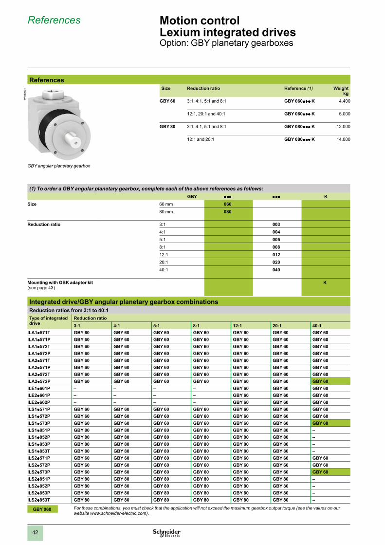
42
References Motion controlLexium integrated drivesOption: GBY planetary gearboxes
ReferencesSize Reduction ratio Reference (1) Weight
kg
GBY 60 3:1, 4:1, 5:1 and 8:1 GBY 060p p p K 4.400
12:1, 20:1 and 40:1 GBY 060p p p K 5.000
GBY 80 3:1, 4:1, 5:1 and 8:1 GBY 080p p p K 12.000
12:1 and 20:1 GBY 080p p p K 14.000
(1) To order a GBY angular planetary gearbox, complete each of the above references as follows:
GBY p p p p p p K
Size 60 mm 060
80 mm 080
Reduction ratio 3:1 003
4:1 004
5:1 005
8:1 008
12:1 012
20:1 020
40:1 040
Mounting with GBK adaptor kit (see page 43)
K
Integrated drive/GBY angular planetary gearbox combinations
Reduction ratios from 3:1 to 40:1
Type of integrated drive
Reduction ratio
3:1 4:1 5:1 8:1 12:1 20:1 40:1
ILA1 p 571T GBY 60 GBY 60 GBY 60 GBY 60 GBY 60 GBY 60 GBY 60
ILA1 p 571P GBY 60 GBY 60 GBY 60 GBY 60 GBY 60 GBY 60 GBY 60
ILA1 p 572T GBY 60 GBY 60 GBY 60 GBY 60 GBY 60 GBY 60 GBY 60
ILA1 p 572P GBY 60 GBY 60 GBY 60 GBY 60 GBY 60 GBY 60 GBY 60
ILA2 p 571T GBY 60 GBY 60 GBY 60 GBY 60 GBY 60 GBY 60 GBY 60
ILA2 p 571P GBY 60 GBY 60 GBY 60 GBY 60 GBY 60 GBY 60 GBY 60
ILA2 p 572T GBY 60 GBY 60 GBY 60 GBY 60 GBY 60 GBY 60 GBY 60
ILA2 p 572P GBY 60 GBY 60 GBY 60 GBY 60 GBY 60 GBY 60 GBY 60
ILE1p 661P – – – – GBY 60 GBY 60 GBY 60
ILE2p 661P – – – – GBY 60 GBY 60 GBY 60
ILE2p 662P – – – – GBY 60 GBY 60 GBY 60
ILS1p 571P GBY 60 GBY 60 GBY 60 GBY 60 GBY 60 GBY 60 GBY 60
ILS1p 572P GBY 60 GBY 60 GBY 60 GBY 60 GBY 60 GBY 60 GBY 60
ILS1p 573P GBY 60 GBY 60 GBY 60 GBY 60 GBY 60 GBY 60 GBY 60
ILS1p 851P GBY 80 GBY 80 GBY 80 GBY 80 GBY 80 GBY 80 –
ILS1p 852P GBY 80 GBY 80 GBY 80 GBY 80 GBY 80 GBY 80 –
ILS1p 853P GBY 80 GBY 80 GBY 80 GBY 80 GBY 80 GBY 80 –
ILS1p 853T GBY 80 GBY 80 GBY 80 GBY 80 GBY 80 GBY 80 –
ILS2p 571P GBY 60 GBY 60 GBY 60 GBY 60 GBY 60 GBY 60 GBY 60
ILS2p 572P GBY 60 GBY 60 GBY 60 GBY 60 GBY 60 GBY 60 GBY 60
ILS2p 573P GBY 60 GBY 60 GBY 60 GBY 60 GBY 60 GBY 60 GBY 60
ILS2p 851P GBY 80 GBY 80 GBY 80 GBY 80 GBY 80 GBY 80 –
ILS2p 852P GBY 80 GBY 80 GBY 80 GBY 80 GBY 80 GBY 80 –
ILS2p 853P GBY 80 GBY 80 GBY 80 GBY 80 GBY 80 GBY 80 –
ILS2p 853T GBY 80 GBY 80 GBY 80 GBY 80 GBY 80 GBY 80 –
GBY 060 For these combinations, you must check that the application will not exceed the maximum gearbox output torque (see the values on our website www.schneider-electric.com).
GBY angular planetary gearbox
PF
080937
2
1
3
4
5
6
7
8
9
10
2
1
3
4
5
6
7
8
9
10

43
References
To order a GBK adaptor kit (1), complete each reference as follows:
GBK p p p p p p p F
Size of GBX or GBY planetary gearbox
Housing diameter 40 mm 040
60 mm 060
80 mm 080
Associated integrated drive ILAp p 57, ILSp p 57 057
ILEp p 66 066
ILSp p 85 085
Compatibility All types of motor 0
1 or 2 stage motors 2
3 stage motor 3
Integrated drive adaptation For ILA integrated drive A
For ILE integrated drive E
For ILS integrated drive S
Integrated drive/GBK adaptor kit combinationType of gearbox ILAp p 571 ILAp p 572 ILE1 p 661 ILE2 p 662 ILS p p 571 ILS p p 572 ILS p p 573 ILS p p 851 ILS p p 852 ILS p p 853
GBK 060 0570A
GBK 040 0660E
GBK 060 0660E
GBK 060 0572S
GBK 060 0573S
GBK 080 0852S
GBK 080 0853S
Compatible
Not compatible
(1) Weight of adaptor kit:
bGBK 040 0660E: 0.244 kg
b
GBK 060 0570A: 0.210 kg
bGBK 060 0572S: 0.223 kg
b
GBK 060 0573S: 0.218 kg
bGBK 060 0660E: 0.255 kg
b
GBK 080 0852S: 0.423 kg
bGBK 080 0853S: 0.416 kg
References Motion controlLexium integrated drivesOption: adaptor kit for GBp planetary gearboxes
2
1
3
4
5
6
7
8
9
10
2
1
3
4
5
6
7
8
9
10

44
Presentation Lexium ILP p R integrated drives equipped with an RS 485 serial link interface comprise a 2-phase stepper motor and control electronics with integrated programmable motion controller.
They also have a multifunction interface which supports up to 11 signals for easy adaptation to different applications.
The control section comprises control electronics and a power stage which share a common power supply.
They are available in four fl ange sizes (36 mm, 42 mm, 57 mm and 85 mm).
Lexium ILP p R integrated drives can operate on the following power supplies:
b24 V to 48 V DC for all motor types
b
230 V AC for 85 mm fl ange motors
Application example: material handling by automatic palletizer
Automatic pallettizers meet the increasing need to transport products over long distances for storage management: a truck transports products to place them in position individually according to the palletization plan.
The Lexium ILPp R integrated drive is used to activate opening and closing of the pallet truck grabs and check that the product has not become jammed.
InterfacesILPp R integrated drives are equipped with the following interfaces:
b RS 485 serial link interface b Multifunction interface
RS 485 serial link interface
The RS 485 serial link interface is used for commissioning, programming and maintaining ILP p R integrated drives using Lexium CT PC software (see page 5).
In order to simplify commissioning and maintenance, the software can use a direct link via an RS 485/USB converter.
Presentation Motion controlLexium integrated drivesILPp R for RS 485 serial link With 2-phase stepper motor
ILPp R for RS 485 serial link with integrated motion controller
45
Presentation (continued) Motion controlLexium integrated drivesILP p R for RS 485 serial linkWith 2-phase stepper motor
Interfaces (continued)Multifunction interface
The multifunction interface supports the following signals:
b5 to 24 V signals, confi gurable as positive logic (Sink) or negative logic (Source) inputs or outputs
b
An analog signal, confi gurable for voltage or current
b0 to 5 V signal confi gurable as a capture input or trip output (version with industrial connector only)
b
Two 0 to 5 V pulse/direction (P/D) signals, confi gurable as inputs or outputs (version with industrial connector only)
24 V I/O
The multifunction interface has 4 or 8 I/O, depending on the chosen type of connection:
b Version with fl ying leads or printed circuit board connectors: Four 5 to 24 V signals (positive logic (Sink) or negative logic (Source) inputs or outputs)
b Version with industrial connectors: Eight 5 to 24 V signals, confi gurable as positive logic (Sink) or negative logic (Source) inputs or outputs
The signals can be used for the following predefi ned functions: b Input functions:
Homing, + limit, - limit, go, stop, pause, JOG+, JOG-, universal function
bOutput functions:
motion, error, stalling, change of speed, universal function
Analog input
The analog input is available on all models of ILPp R integrated drive.
It can be confi gured for voltage (0…5 V or 0…10 V c ) or current (4 to 20 mA or 0 to 20 mA).
5 V capture input/trip output
This input/output is available on ILPp R integrated drives equipped with industrial connectors.
The high speed signal is used to capture the position of the axis or to control an external event when it is set as a trip output.
Pulse/direction (P/D) I/O
Pulse/direction (P/D) signals are available on ILPp R integrated drives equipped with industrial connectors.
They can control a third-party device. The signals can be transmitted from a master controller, for example a Lexium Controller, or from another Lexium ILPp R integrated drive.
Special technical features
bHigh continuous maximum torque
b
Good speed stability characteristics
bHigh resolution positioning
b
Complete 1 or 2-character instruction set
bConfi gurable I/O
b
Very compact
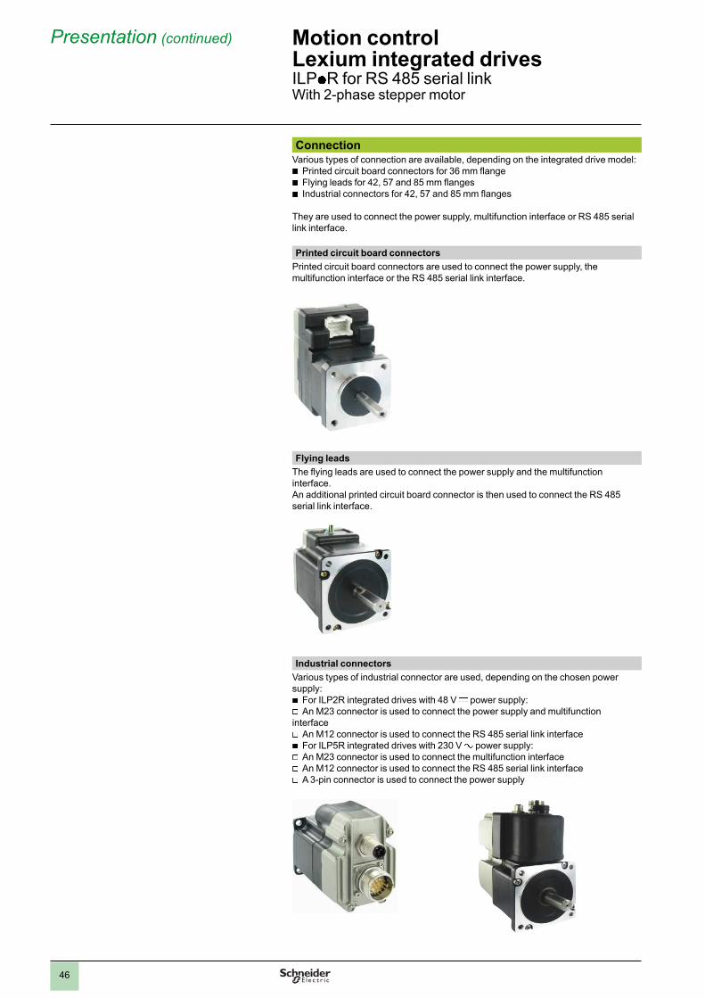
46
Presentation (continued) Motion controlLexium integrated drivesILPp R for RS 485 serial link With 2-phase stepper motor
ConnectionVarious types of connection are available, depending on the integrated drive model:
b
Printed circuit board connectors for 36 mm fl ange
bFlying leads for 42, 57 and 85 mm fl anges
b
Industrial connectors for 42, 57 and 85 mm fl anges
They are used to connect the power supply, multifunction interface or RS 485 serial link interface.
Printed circuit board connectors
Printed circuit board connectors are used to connect the power supply, the multifunction interface or the RS 485 serial link interface.
Flying leads
The fl ying leads are used to connect the power supply and the multifunction interface.An additional printed circuit board connector is then used to connect the RS 485 serial link interface.
Industrial connectors
Various types of industrial connector are used, depending on the chosen power supply:
b
For ILP2R integrated drives with 48 V c power supply:
vAn M23 connector is used to connect the power supply and multifunction
interface
vAn M12 connector is used to connect the RS 485 serial link interface
b
For ILP5R integrated drives with 230 V a power supply:
vAn M23 connector is used to connect the multifunction interface
v
An M12 connector is used to connect the RS 485 serial link interface
vA 3-pin connector is used to connect the power supply
47
Presentation (continued) Motion controlLexium integrated drivesILP p R for RS 485 serial link With 2-phase stepper motor
Main functionsLexium ILPp R integrated drives include the main functions required for motion control.
All function parameters are set via the RS 485 serial link interface using Lexium CT PC software.The parameters can be saved to the Lexium ILP p R integrated drive's internal non-volatile memory.
Operating modes
Lexium ILPp R integrated drives can function in two operating modes:
bManual mode (JOG)
In this mode, the commands and parameters are controlled directly with the Lexium CT PC software.
b
Programmable modeThis mode is used to save programs in the motion controller incorporated in the Lexium ILPp R drive.
Motion functions
b
Setting the number of steps (200 to 51,200)
bSpeed profi le
b
Point-to-point mode
bHoming
b
Electronic gearbox mode (for the version with industrial connectors)
Other functions
b
Setting the transmission rate
bConfi guring the I/O signals
b
Setting the motor phase current (1 to 100% of nominal current)
bMathematical functions (addition, subtraction, division, multiplication, AND, OR, XOR, NOT functions , etc.)
b
Trip functions
bEncoder functions
b
Program functions (calling a subroutine, creation of operation variables, etc.)
b…
Note: For details of available functions, please visit our website www.schneider-electric.com.

2
1
3
4
5
6
7
8
9
10
2
1
3
4
5
6
7
8
9
10
48
Description Motion controlLexium integrated drivesILPp R for RS 485 serial linkWith 2-phase stepper motor
DescriptionILPp R integrated drives equipped with an RS 485 serial link interface comprise a 2-phase stepper motor and control electronics with integrated programmable motion controller.
The integrated drive is programmed via the RS 485 serial link interface using Lexium CT PC software which can be used for point-to-point or multipoint confi guration.
There are three types of connection, depending on the fl ange size:
bFlying leads
b
Industrial connectors
bPrinted circuit board connectors
Connection types
Flying leads
Connection via industrial connector
Connection via printed circuit board connector

2
1
3
4
5
6
7
8
9
10
2
1
3
4
5
6
7
8
9
10
49
References Example: I L P 2 R 3 6 1 M N 1 A
Motor typeP = 2-phase stepper motor
I L P 2 R 3 6 1 M N 1 A
Supply voltage2 = 24…48 V c5 = 230 V a (for 85 mm fl ange only)
I L P 2 R 3 6 1 M N 1 A
Communication interfaceR = RS 485
I L P 2 R 3 6 1 M N 1 A
Flange size36 = 36 mm42 = 42 mm57 = 57 mm85 = 85 mm
I L P 2 R 3 6 1 M N 1 A
Drive type (1)1 = ILPp Rp p 12 = ILPp Rp p 23 = ILPp Rp p 34 = ILPp Rp p 4
I L P 2 R 3 6 1 M N 1 A
Speed/torque indexM = medium torque, medium rotation speed
I L P 2 R 3 6 1 M N 1 A
ConnectionB = fl ying leads (except for motor with 36 mm fl ange ( c ) and 85 mm fl ange (a ))C = industrial connector (except for motor with 36 mm fl ange ( c ) and 85 mm fl ange (c ))N = printed circuit board connector (for motor with 36 mm fl ange (c ))
I L P 2 R 3 6 1 M N 1 A
Sensor type1 = reference pulse sensor (Zero marker)
I L P 2 R 3 6 1 M N 1 A
Holding brakeA = without holding brake
I L P 2 R 3 6 1 M N 1 A
(1) See the main characteristics and dimensions according to the type of drive in the table below:
References Motion controlLexium integrated drivesILP p R for RS 485 serial linkWith 2-phase stepper motor
Drive ILP2R ILP5R
361 421 422 423 571 572 573 574 851 852 853 851 852 853
Nominal supplyvoltage
V c 24…48 –
V a – 230
Holding torque Nm 0.11 0.19 0.33 0.39 0.63 0.86 1.44 1.77 2.13 3.12 5.87 2.16 3.16 4.79
Dimensions (overall in mm)
Flying leads W x H – 42.7 x 58.3 56.4 x 75.2 86.1 x 94.7 –
D – 55.9 61.7 70.4 67.3 76.7 98.6 134.1 96.8 116.8 156.7 –
With industrialconnector
W x H – 42.9 x 70.9 56.4 x 75.2 – 87.8 x 164.2
D – 77.7 83.6 92.2 88.4 97 118.6 – – 155 174.3 214.3
With printed circuit board connector
W x H 35.6 x 52 –
D 48.5 –
Note: See all the data (characteristics, dimensions) on our website www.schneider-electric.com.
ILPp R integrated drive for RS 485 serial link

50
Presentation Lexium ILTpA integrated drives equipped with a CANopen machine bus interface comprise a 2-phase stepper motor and control electronics.
They also have a multifunction interface which supports up to 11 signals for easy adaptation to different applications.
The control section comprises control electronics and a power stage which share a common power supply.
They are available in four fl ange sizes (36 mm, 42 mm, 57 mm and 85 mm).
Lexium ILTpA integrated drives can operate on the following power supplies: b 24 V to 48 V DC for all motor types b 230 V AC for 85 mm fl ange motors
Application example: manufacture of solar panelsDuring their manufacture, solar panels are transported from one workstation to another via a conveyor belt. In order to double production, two conveyors are used simultaneously to transport two lines of solar panels. The panels are stopped at each workstation, the position being determined using a camera placed inside the workstation. The excellent positioning accuracy of Lexium ILTpA integrated drives makes them ideal for controlling the conveyor. Three Lexium ILTpA integrated drives are used for each conveyor line, with a total of six Lexium ILTpA drives operating simultaneously in each workstation.
InterfacesILTpA integrated drives are equipped with the following interfaces:
b CANopen machine bus interface b Multifunction interface
CANopen machine bus interfaceThe CANopen machine bus interface is used for confi guring and controlling the ILTpA integrated drive.
It is also used to connect the Lexium CT PC software (see page 5). A CANopen/USB converter is then necessary (see accessories page 60).
Presentation Motion controlLexium integrated drivesILTpA for CANopen machine busWith 2-phase stepper motor
ILTpA for CANopen machine bus

51
Presentation (continued) Motion controlLexium integrated drivesILTp A for CANopen machine busWith 2-phase stepper motor
Interfaces (continued)
Multifunction interface
The multifunction interface supports the following signals:
b5 to 24 V signals, confi gurable as positive logic (Sink) or negative logic (Source) inputs or outputs
b
An analog signal, confi gurable for voltage or current
b0 to 5 V signal confi gurable as a capture input or trip output (version with industrial connector only)
b
Two 0 to 5 V pulse/direction (P/D) signals, confi gurable as inputs or outputs (version with industrial connector only)
24 V I/O
The multifunction interface has 4 or 8 I/O, depending on the chosen type of connection:
b Version with fl ying leads or printed circuit board connectors: Four 24 V signals (positive logic (Sink) or negative logic (Source) inputs or outputs)
b Version with industrial connectors: Eight 24 V signals, confi gurable as positive logic (Sink) or negative logic (Source) inputs or outputs
The signals can be used for the following predefi ned functions: b Input functions:
Homing, + limit, - limit, go, stop, pause, JOG+, JOG-, universal function
bOutput functions:
motion, error, stalling, change of speed, universal function
Analog input
The analog input is available on all models of ILTp A integrated drive.
It can be confi gured for voltage (0…5 V or 0…10 V c ) or current (4 to 20 mA or 0 to 20 mA).
5 V capture input/trip output
This input/output is available on ILT p A integrated drives equipped with industrial connectors.
The high speed signal is used to capture the position of the axis or to control an external event when it is set as a trip output.
Pulse/direction (P/D) I/O
Pulse/direction (P/D) signals are available on ILT p A integrated drives equipped with industrial connectors.
They can control a third-party device. The signals can be transmitted from a master controller, for example a Lexium Controller.
Special technical features
bHigh continuous maximum torque
b
Good speed stability characteristics
bHigh resolution positioning
b
Complete 1 or 2-character instruction set
bConfi gurable I/O
b
Very compact

52
Presentation (continued) Motion controlLexium integrated drivesILTp A for CANopen machine busWith 2-phase stepper motor
ConnectionVarious types of connection are available, depending on the integrated drive model:
b
Printed circuit board connectors for 36 mm fl ange
bFlying leads for 42, 57 and 85 mm fl anges
b
Industrial connectors for 42, 57 and 85 mm fl anges
They are used to connect the power supply, multifunction interface or RS 485 serial link interface.
Printed circuit board connectors
Printed circuit board connectors are used to connect the power supply and the multifunction interface.
An additional 9-way male SUB-D connector is then used to connect the CANopen machine bus interface.
Flying leads
The fl ying leads are used to connect the power supply and the multifunction interface.
An additional 9-way male SUB-D connector is then used to connect the CANopen machine bus interface.
Industrial connectors
Various types of industrial connector are used, depending on the chosen power supply:
b
For ILT2A integrated drives with 48 V c power supply:
vAn M23 connector is used to connect the power supply and multifunction
interface
vAn M12 connector is used to connect the CANopen machine bus interface
b
For ILT5A integrated drives with 230 V a power supply:
vAn M23 connector is used to connect the multifunction interface
v
An M12 connector is used to connect the CANopen machine bus interface
vA 3-pin connector is used to connect the power supply

53
Presentation (continued) Motion controlLexium integrated drivesILTp A for CANopen machine busWith 2-phase stepper motor
Main functionsLexium ILT p A integrated drives include the main functions required for motion control, in particular:
Operating modes
The following operating modes can be set via the communication bus or using Lexium CT PC software:
b
Speed profi le
bPosition profi le
b
Homing
Other operating modes can be activated via the communication bus or the Lexium CT PC software:
b
Confi guring the I/O
bSetting the motion profi le via the profi le generator
b
Triggering the Quick Stop function
bFast position capture via an input signal
Note: For details of available functions, please visit our website www.schneider-electric.com.

2
1
3
4
5
6
7
8
9
10
2
1
3
4
5
6
7
8
9
10
54
Description Motion controlLexium integrated drivesILTp A for CANopen machine busWith 2-phase stepper motor
DescriptionILTp A integrated drives equipped with a CANopen machine bus interface comprise a 2-phase stepper motor and control electronics.
They have a CANopen machine bus communication interface which supports the DS 301 and DSP 402 device profi les.
There are three types of connection, depending on the fl ange size:
bFlying leads
b
Industrial connectors
bPrinted circuit board connectors
Connection types
Flying leads
Connection via industrial connector
Connection via printed circuit board connector

2
1
3
4
5
6
7
8
9
10
2
1
3
4
5
6
7
8
9
10
55
References Example: I L T 2 A 3 6 1 M N 1 A
Motor typeT = 2-phase stepper motor
I L T 2 A 3 6 1 M N 1 A
Supply voltage2 = 24…48 V c5 = 230 V a (for 85 mm fl ange only)
I L T 2 A 3 6 1 M N 1 A
Communication interfaceA = CANopen DS 301 or DSP 402
I L T 2 A 3 6 1 M N 1 A
Flange size36 = 36 mm42 = 42 mm57 = 57 mm85 = 85 mm
I L T 2 A 3 6 1 M N 1 A
Drive type (1)1 = ILT p Ap p 12 = ILT p Ap p 23 = ILT p Ap p 34 = ILT p Ap p 4
I L T 2 A 3 6 1 M N 1 A
Speed/torque indexM = medium torque, medium rotation speed
I L T 2 A 3 6 1 M N 1 A
ConnectionB = fl ying leads (except for motor with 36 mm fl ange ( c ) and 85 mm fl ange (a ))C = industrial connector (except for motor with 36 mm fl ange ( c ) and 85 mm fl ange (c ))N = printed circuit board connector (for motor with 36 mm fl ange (c ))
I L T 2 A 3 6 1 M N 1 A
Sensor type1 = reference pulse sensor (Zero marker)
I L T 2 A 3 6 1 M N 1 A
Holding brakeA = without holding brake
I L T 2 A 3 6 1 M N 1 A
(1) See the main characteristics and dimensions according to the type of drive in the table below:
References Motion controlLexium integrated drivesILTp A for CANopen machine busWith 2-phase stepper motor
Drive ILT2A ILT5A
361 421 422 423 571 572 573 574 851 852 853 851 852 853
Nominal supplyvoltage
V c 24…48 –
V a – 230
Holding torque Nm 0.11 0.19 0.33 0.39 0.63 0.86 1.44 1.77 2.13 3.12 5.87 2.16 3.16 4.79
Dimensions (overall in mm)
Flying leads W x H – 42.7 x 58.3 56.4 x 75.2 86.1 x 105.5 –
D – 55.9 61.7 70.4 67.3 76.7 98.6 134.1 96.8 116.8 156.7 –
With industrialconnector
W x H – 42.9 x 70.9 56.4 x 75.2 – 87.8 x 164.2
D – 77.7 83.6 92.2 88.4 97 118.6 – – 155 174.3 214.3
With printed circuit board connector
W x H 35.6 x 52.3 –
D 49 –
Note: See all the data (characteristics, dimensions) on our website www.schneider-electric.com.
ILTp A integrated drive for CANopen machine bus
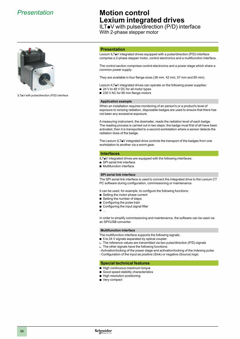
56
Presentation Lexium ILTp V integrated drives equipped with a pulse/direction (P/D) interface comprise a 2-phase stepper motor, control electronics and a multifunction interface.
The control section comprises control electronics and a power stage which share a common power supply.
They are available in four fl ange sizes (36 mm, 42 mm, 57 mm and 85 mm).
Lexium ILTp V integrated drives can operate on the following power supplies:
b24 V to 48 V DC for all motor types
b
230 V AC for 85 mm fl ange motors
Application example
When an installation requires monitoring of an person's or a product's level of exposure to ionizing radiation, disposable badges are used to ensure that there has not been any excessive exposure.
A measuring instrument, the dosimeter, reads the radiation level of each badge.The reading process is carried out in two steps: the badge must fi rst of all have been activated, then it is transported to a second workstation where a sensor detects the radiation dose of the badge.
The Lexium ILT p V integrated drive controls the transport of the badges from one workstation to another via a worm gear.
InterfacesILTp V integrated drives are equipped with the following interfaces:
b SPI serial link interface b Multifunction interface
SPI serial link interface
The SPI serial link interface is used to connect the integrated drive to the Lexium CT PC software during confi guration, commissioning or maintenance.
It can be used, for example, to confi gure the following functions:
bSetting the motor phase current
b
Setting the number of steps
bConfi guring the pulse train
b
Confi guring the input signal fi lter
b...
In order to simplify commissioning and maintenance, the software can be used via an SPI/USB converter.
Multifunction interface
The multifunction interface supports the following signals:
b5 to 24 V signals separated by optical coupler:
v
The reference values are transmitted via two pulse/direction (P/D) signals
vThe other signals have the following functions:
- Activation/locking of the power stage and activation/locking of the indexing pulse- Confi guration of the input as positive (Sink) or negative (Source) logic
Special technical features
bHigh continuous maximum torque
b
Good speed stability characteristics
bHigh resolution positioning
b
Very compact
Presentation Motion controlLexium integrated drivesILTp V with pulse/direction (P/D) interface With 2-phase stepper motor
ILTp V with pulse/direction (P/D) interface

57
Presentation (continued) Motion controlLexium integrated drivesILTp V with pulse/direction (P/D) interfaceWith 2-phase stepper motor
ConnectionVarious types of connection are available, depending on the integrated drive model:
b
Printed circuit board connectors for 36 mm fl ange
bFlying leads for 42, 57 and 85 mm fl anges
b
Industrial connectors for 42, 57 and 85 mm fl anges
They are used to connect the power supply, multifunction interface or commissioning interface.
Printed circuit board connectors
Printed circuit board connectors are used to connect the power supply, the multifunction interface and the SPI serial link.
Flying leads
The fl ying leads are used to connect the power supply and the multifunction interface.
An additional printed circuit board connector is then used to connect the SPI serial link interface.
Industrial connectors
Various types of industrial connector are used, depending on the chosen power supply:
b
For ILT2V integrated drives with 48 V c power supply:
vAn M23 connector is used to connect the power supply, multifunction interface
and SPI serial link
b
For ILT5V integrated drives with 230 V a power supply:
vAn M23 connector is used to connect the multifunction interface and SPI serial
link
vA 3-pin connector is used to connect the power supply
Main functions
Confi guration by parameter switch
The following functions can be set on ILTp V integrated drives via the parameter switch:
b
Setting the number of steps
bSetting the motor phase current
b
Reducing the motor phase current
bInput signal functions:
v
Transmission of the reference value via pulse/direction (PULSE/DIR) or encoder (A/B) signals
v
Activation/locking of the power stage (ENABLE/GATE input signal)
vActivation/locking of the indexing pulse (ENABLE/GATE input signal)
b
Adjusting the input fi lter
Note: For details of available functions, please visit our website www.schneider-electric.com.
Integrated drive with fl ying leads
Integrated drives with industrial connector
Integrated drive with printed circuit board connector

2
1
3
4
5
6
7
8
9
10
2
1
3
4
5
6
7
8
9
10
58
Description Motion controlLexium integrated drivesILTp V with pulse/direction (P/D) interface With 2-phase stepper motor
DescriptionILTp V integrated drives equipped with a pulse/direction (P/D) interface comprise a 2-phase stepper motor and control electronics.
The confi guration of ILTp V integrated drives can be modifi ed on the fl y or downloaded and saved to a non-volatile memory using the Lexium CT PC software tool. The parameters can be modifi ed via the SPI serial link interface.
There are three types of connection, depending on the fl ange size:
bFlying leads
b
Industrial connectors
bPrinted circuit board connectors
Connection types
Flying leads
Connection via industrial connector
Connection via printed circuit board connector

2
1
3
4
5
6
7
8
9
10
2
1
3
4
5
6
7
8
9
10
59
References Example: I L T 2 V 3 6 1 M N 0 A
Motor typeT = 2-phase stepper motor
I L T 2 V 3 6 1 M N 0 A
Supply voltage2 = 24…48 V c5 = 230 V a (for 85 mm fl ange only)
I L T 2 V 3 6 1 M N 0 A
Communication interfaceV = pulse/direction (P/D)
I L T 2 V 3 6 1 M N 0 A
Flange size36 =36 mm42 = 42 mm57 = 57 mm85 = 85 mm
I L T 2 V 3 6 1 M N 0 A
Drive type (1)1 = ILT p Vp p 12 = ILT p Vp p 23 = ILT p Vp p 34 = ILT p Vp p 4
I L T 2 V 3 6 1 M N 0 A
Speed/torque indexM = medium torque, medium rotation speed
I L T 1T V 3 6 1 M N 0 A
ConnectionB = fl ying leads (except for motor with 36mm fl ange ( c ) and 85 mm fl ange (a ))C = industrial connector (except for motor with 36 mm fl ange ( c ) and 85 mm fl ange (c ))N = printed circuit board connector (for motor with 36 mm fl ange (c ))
I L T 2 V 3 6 1 M N 0 A
Sensor type0 = without sensor
I L T 2 V 3 6 1 M N 0 A
Holding brakeA = without holding brake
I L T 2 V 3 6 1 M N 0 A
(1) See the main characteristics and dimensions according to the type of drive in the table below:
References Motion controlLexium integrated drivesILTp V with pulse/direction (P/D) interface With 2-phase stepper motor
Drive ILT2V ILT5V
361 421 422 423 571 572 573 574 851 852 853 851 852 853
Nominal supplyvoltage
V c 24…48 –
V a – 230
Holding torque Nm 0.11 0.19 0.33 0.39 0.63 0.86 1.44 1.77 2.13 3.12 5.87 2.16 3.16 4.79
Dimensions (overall in mm)
Flying leads W x H – 42.7 x 58.3 56.4 x 75.2 86.1 x 94.7 –
D – 55.9 61.7 70.4 67.3 76.7 98.6 134.1 96.8 116.8 156.7 –
With industrialconnector
W x H – 42.9 x 70.9 56.4 x 75.2 – 87.8 x 164.2
D – 77.7 83.6 92.2 88.4 97 118.6 – – 155 174.3 214.3
With printed circuit board connector
W x H 35.6 x 52 –
D 48.5 –
Note: See all the data (characteristics, dimensions) on our website www.schneider-electric.com.
ILTp V integrated drive with pulse/direction (P/D) interface
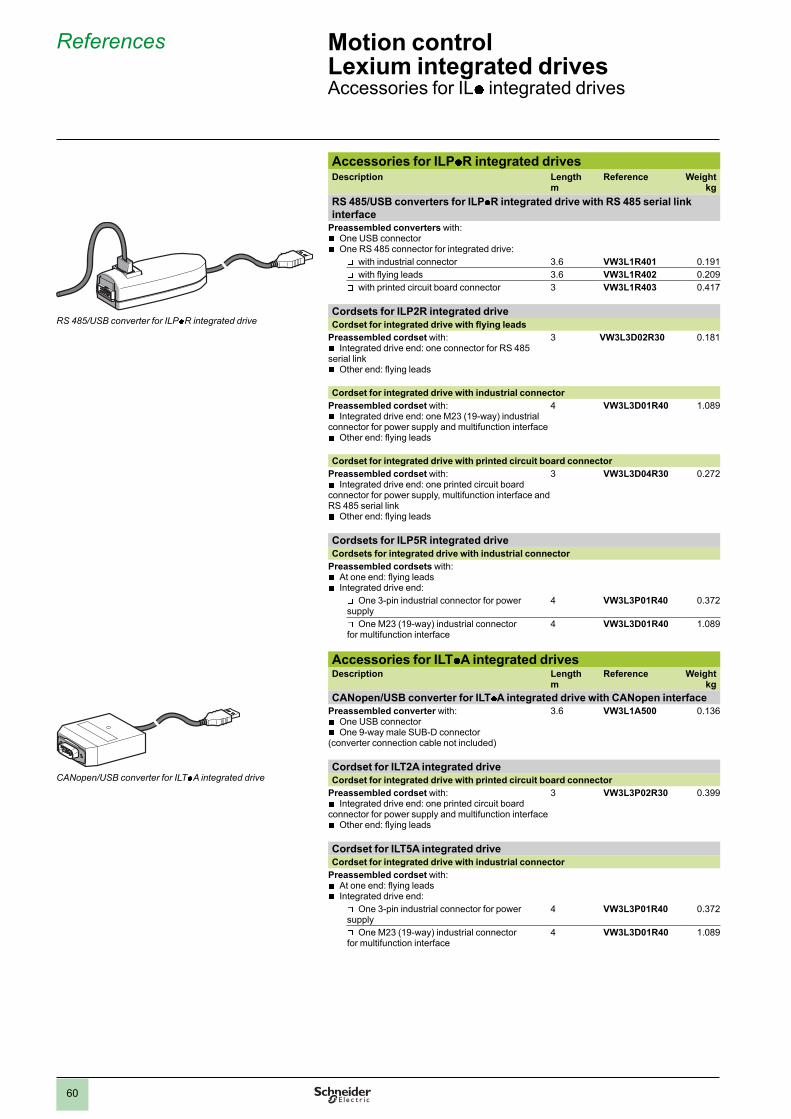
60
References Motion controlLexium integrated drivesAccessories for ILp integrated drives
Accessories for ILPp
R integrated drivesDescription Length
mReference Weight
kg
RS 485/USB converters for ILPp R integrated drive with RS 485 serial link
interface
Preassembled converters with:
bOne USB connector
b
One RS 485 connector for integrated drive:
v
with industrial connector 3.6 VW3L1R401 0.191
v
with fl ying leads 3.6 VW3L1R402 0.209
v
with printed circuit board connector 3 VW3L1R403 0.417
Cordsets for ILP2R integrated drive
Cordset for integrated drive with fl ying leads
Preassembled cordset with:
bIntegrated drive end: one connector for RS 485
serial link
bOther end: fl ying leads
3 VW3L3D02R30 0.181
Cordset for integrated drive with industrial connector
Preassembled cordset with:
bIntegrated drive end: one M23 (19-way) industrial
connector for power supply and multifunction interface
bOther end: fl ying leads
4 VW3L3D01R40 1.089
Cordset for integrated drive with printed circuit board connector
Preassembled cordset with:
bIntegrated drive end: one printed circuit board
connector for power supply, multifunction interface and RS 485 serial link
b
Other end: fl ying leads
3 VW3L3D04R30 0.272
Cordsets for ILP5R integrated drive
Cordsets for integrated drive with industrial connector
Preassembled cordsets with:
bAt one end: fl ying leads
b
Integrated drive end:
v
One 3-pin industrial connector for power supply
4 VW3L3P01R40 0.372
v
One M23 (19-way) industrial connector for multifunction interface
4 VW3L3D01R40 1.089
Accessories for ILTp
A integrated drivesDescription Length
mReference Weight
kg
CANopen/USB converter for ILT p A integrated drive with CANopen interface
Preassembled converter with:
bOne USB connector
b
One 9-way male SUB-D connector(converter connection cable not included)
3.6 VW3L1A500 0.136
Cordset for ILT2A integrated drive
Cordset for integrated drive with printed circuit board connector
Preassembled cordset with:
bIntegrated drive end: one printed circuit board
connector for power supply and multifunction interface
bOther end: fl ying leads
3 VW3L3P02R30 0.399
Cordset for ILT5A integrated drive
Cordset for integrated drive with industrial connector
Preassembled cordset with:
bAt one end: fl ying leads
b
Integrated drive end:
v
One 3-pin industrial connector for power supply
4 VW3L3P01R40 0.372
v
One M23 (19-way) industrial connector for multifunction interface
4 VW3L3D01R40 1.089
RS 485/USB converter for ILPp R integrated drive
CANopen/USB converter for ILTp A integrated drive
2
1
3
4
5
6
7
8
9
10
2
1
3
4
5
6
7
8
9
10
1.0

61
References Motion controlintegrated drivesAccessories for ILT p V integrated drives
Accessories for ILTp
V integrated drivesDescription Length
mReference Weight
kg
SPI/USB converters for ILTp V integrated drive with pulse/direction (P/D)
interface
Preassembled converters with:
bOne USB connector
b
One SPI connector for integrated drive:
v
with fl ying leads 3.6 VW3L1V300 0.127
v
with industrial connector 3.6 VW3L1V301 0.179
v
with printed circuit board connector 3.6 VW3L1V305 0.399
Cordsets for ILT2V integrated drive
Cordset for integrated drive with industrial connector
Preassembled cordset with:
bIntegrated drive end: one M23 (19-way) industrial
connector for power supply, multifunction interface and SPI serial link
b
Other end: fl ying leads
4 VW3L3D01R40 1.089
Cordset for integrated drive with printed circuit board connector
Preassembled cordset with:
bIntegrated drive end: one printed circuit board
connector for power supply, multifunction interface and SPI serial link
b
Other end: fl ying leads
3 VW3L3D04R30 0.272
Cordset for ILT5V integrated drive
Cordset for integrated drive with industrial connector
Preassembled cordset with:
bAt one end: fl ying leads
b
Integrated drive end:
v
One 3-pin industrial connector for power supply
4 VW3L3P01R40 0.372
v
One M23 (19-way) industrial connector for multifunction interface
4 VW3L3D01R40 1.089
SPI/USB converter for ILTp V integrated drive
2
1
3
4
5
6
7
8
9
10
2
1
3
4
5
6
7
8
9
10

The information provided in this documentation contains general descriptions and/or technical
characteristics of the performance of the products contained herein. This documentation is not
intended as a substitute for and is not to be used for determining suitability or reliability of these
products for specifi c user applications. It is the duty of any such user or integrator to perform the
appropriate and complete risk analysis, evaluation and testing of the products with respect to the
relevant specifi c application or use thereof. Neither Schneider Electric nor any of its affi liates or
subsidiaries shall be responsible or liable for misuse of the information contained herein.
Design: Schneider Electric
Photos: Schneider Electric
Printed by:
Head Offi ce
35, rue Joseph Monier
F-92500 Rueil-Malmaison
France
www.schneider-electric.comSchneider Electric Industries SAS
DIA
7E
D21107
01E
N
ART. 960589


![Twido Modbus mit Magelis, Altivar, Lexium, TesysU System ... SYSTEMOW AUTOMATYKI TL2007/T… · Twido Modbus mit Magelis, Altivar, Lexium, TesysU System User Guide [Quellcode] 00](https://img.pdfslide.tips/doc/110x75/5a9e2b2a7f8b9ad2298e2af1/twido-modbus-mit-magelis-altivar-lexium-tesysu-system-systemow-automatyki.jpg)