Embed Size (px)
Citation preview

R
LCD TVSERVICE MANUAL
CAUTIONBEFORE SERVICING THE CHASSIS,READ THE SAFETY PRECAUTIONS IN THIS MANUAL.
CHASSIS : LP78A
MODEL : 32LC7R/51/53 32LC7R/51/53-ZAMODEL : 32LC52 32LC52-ZCMODEL : 32LC54 32LC54-ZD
website:http://biz.LGservice.comInternal Use Only

- 2 -Copyright © 2007 LG Electronics. Inc. All right reserved. Only for training and service purposes
LGE Internal Use Only
CONTENTS
CONTENTS .............................................................................................. 2
SAFETY PRECAUTIONS ..........................................................................3
SPECIFICATION ........................................................................................6
ADJUSTMENT INSTRUCTION .................................................................9
TROUBLE SHOOTING ............................................................................17
BLOCK DIAGRAM...................................................................................25
EXPLODED VIEW .................................................................................. 26
EXPLODED VIEW PARTS LIST..............................................................27
REPLACEMENT PARTS LIST ............................................................... 28
SVC. SHEET ...............................................................................................

Copyright © 2007 LG Electronics. Inc. All right reserved. Only for training and service purposes
LGE Internal Use Only- 3 -
SAFETY PRECAUTIONS
Many electrical and mechanical parts in this chassis have special safety-related characteristics. These parts are identified by in theSchematic Diagram and Replacement Parts List. It is essential that these special safety parts should be replaced with the same components as recommended in this manual to preventShock, Fire, or other Hazards. Do not modify the original design without permission of manufacturer.
General Guidance
An isolation Transformer should always be used during theservicing of a receiver whose chassis is not isolated from the ACpower line. Use a transformer of adequate power rating as thisprotects the technician from accidents resulting in personal injuryfrom electrical shocks.
It will also protect the receiver and it's components from beingdamaged by accidental shorts of the circuitry that may beinadvertently introduced during the service operation.
If any fuse (or Fusible Resistor) in this TV receiver is blown,replace it with the specified.
When replacing a high wattage resistor (Oxide Metal Film Resistor,over 1W), keep the resistor 10mm away from PCB.
Keep wires away from high voltage or high temperature parts.
Before returning the receiver to the customer,
always perform an AC leakage current check on the exposedmetallic parts of the cabinet, such as antennas, terminals, etc., tobe sure the set is safe to operate without damage of electricalshock.
Leakage Current Cold Check(Antenna Cold Check)With the instrument AC plug removed from AC source, connect anelectrical jumper across the two AC plug prongs. Place the ACswitch in the on position, connect one lead of ohm-meter to the ACplug prongs tied together and touch other ohm-meter lead in turn toeach exposed metallic parts such as antenna terminals, phonejacks, etc. If the exposed metallic part has a return path to the chassis, themeasured resistance should be between 1MΩ and 5.2MΩ. When the exposed metal has no return path to the chassis thereading must be infinite.An other abnormality exists that must be corrected before thereceiver is returned to the customer.
Leakage Current Hot Check (See below Figure) Plug the AC cord directly into the AC outlet.
Do not use a line Isolation Transformer during this check.Connect 1.5K/10watt resistor in parallel with a 0.15uF capacitorbetween a known good earth ground (Water Pipe, Conduit, etc.)and the exposed metallic parts.Measure the AC voltage across the resistor using AC voltmeterwith 1000 ohms/volt or more sensitivity.Reverse plug the AC cord into the AC outlet and repeat AC voltagemeasurements for each exposed metallic part. Any voltagemeasured must not exceed 0.75 volt RMS which is corresponds to0.5mA.In case any measurement is out of the limits specified, there ispossibility of shock hazard and the set must be checked andrepaired before it is returned to the customer.
Leakage Current Hot Check circuit
1.5 Kohm/10W
To Instrument’sexposed METALLIC PARTS
Good Earth Groundsuch as WATER PIPE,CONDUIT etc.
AC Volt-meter
IMPORTANT SAFETY NOTICE
0.15uF

Copyright © 2007 LG Electronics. Inc. All right reserved. Only for training and service purposes
LGE Internal Use Only- 4 -
CAUTION: Before servicing receivers covered by this servicemanual and its supplements and addenda, read and follow theSAFETY PRECAUTIONS on page 3 of this publication.NOTE: If unforeseen circumstances create conflict between thefollowing servicing precautions and any of the safety precautions onpage 3 of this publication, always follow the safety precautions.Remember: Safety First.
General Servicing Precautions1. Always unplug the receiver AC power cord from the AC power
source before;a. Removing or reinstalling any component, circuit board
module or any other receiver assembly.b. Disconnecting or reconnecting any receiver electrical plug or
other electrical connection.c. Connecting a test substitute in parallel with an electrolytic
capacitor in the receiver.CAUTION: A wrong part substitution or incorrect polarityinstallation of electrolytic capacitors may result in anexplosion hazard.
2. Test high voltage only by measuring it with an appropriate highvoltage meter or other voltage measuring device (DVM,FETVOM, etc) equipped with a suitable high voltage probe.Do not test high voltage by "drawing an arc".
3. Do not spray chemicals on or near this receiver or any of itsassemblies.
4. Unless specified otherwise in this service manual, cleanelectrical contacts only by applying the following mixture to thecontacts with a pipe cleaner, cotton-tipped stick or comparablenon-abrasive applicator; 10% (by volume) Acetone and 90% (byvolume) isopropyl alcohol (90%-99% strength)CAUTION: This is a flammable mixture.Unless specified otherwise in this service manual, lubrication ofcontacts in not required.
5. Do not defeat any plug/socket B+ voltage interlocks with whichreceivers covered by this service manual might be equipped.
6. Do not apply AC power to this instrument and/or any of itselectrical assemblies unless all solid-state device heat sinks arecorrectly installed.
7. Always connect the test receiver ground lead to the receiverchassis ground before connecting the test receiver positivelead.Always remove the test receiver ground lead last.
8. Use with this receiver only the test fixtures specified in thisservice manual.CAUTION: Do not connect the test fixture ground strap to anyheat sink in this receiver.
Electrostatically Sensitive (ES) DevicesSome semiconductor (solid-state) devices can be damaged easilyby static electricity. Such components commonly are calledElectrostatically Sensitive (ES) Devices. Examples of typical ESdevices are integrated circuits and some field-effect transistors andsemiconductor "chip" components. The following techniquesshould be used to help reduce the incidence of componentdamage caused by static by static electricity.1. Immediately before handling any semiconductor component or
semiconductor-equipped assembly, drain off any electrostaticcharge on your body by touching a known earth ground.Alternatively, obtain and wear a commercially availabledischarging wrist strap device, which should be removed toprevent potential shock reasons prior to applying power to the
unit under test.2. After removing an electrical assembly equipped with ES
devices, place the assembly on a conductive surface such asaluminum foil, to prevent electrostatic charge buildup orexposure of the assembly.
3. Use only a grounded-tip soldering iron to solder or unsolder ESdevices.
4. Use only an anti-static type solder removal device. Some solderremoval devices not classified as "anti-static" can generateelectrical charges sufficient to damage ES devices.
5. Do not use freon-propelled chemicals. These can generateelectrical charges sufficient to damage ES devices.
6. Do not remove a replacement ES device from its protectivepackage until immediately before you are ready to install it.(Most replacement ES devices are packaged with leadselectrically shorted together by conductive foam, aluminum foilor comparable conductive material).
7. Immediately before removing the protective material from theleads of a replacement ES device, touch the protective materialto the chassis or circuit assembly into which the device will beinstalled.CAUTION: Be sure no power is applied to the chassis or circuit,and observe all other safety precautions.
8. Minimize bodily motions when handling unpackagedreplacement ES devices. (Otherwise harmless motion such asthe brushing together of your clothes fabric or the lifting of yourfoot from a carpeted floor can generate static electricitysufficient to damage an ES device.)
General Soldering Guidelines1. Use a grounded-tip, low-wattage soldering iron and appropriate
tip size and shape that will maintain tip temperature within therange or 500°F to 600°F.
2. Use an appropriate gauge of RMA resin-core solder composedof 60 parts tin/40 parts lead.
3. Keep the soldering iron tip clean and well tinned.4. Thoroughly clean the surfaces to be soldered. Use a mall wire-
bristle (0.5 inch, or 1.25cm) brush with a metal handle.Do not use freon-propelled spray-on cleaners.
5. Use the following unsoldering techniquea. Allow the soldering iron tip to reach normal temperature.
(500°F to 600°F)b. Heat the component lead until the solder melts.c. Quickly draw the melted solder with an anti-static, suction-
type solder removal device or with solder braid.CAUTION: Work quickly to avoid overheating the circuitboard printed foil.
6. Use the following soldering technique.a. Allow the soldering iron tip to reach a normal temperature
(500°F to 600°F)b. First, hold the soldering iron tip and solder the strand against
the component lead until the solder melts.c. Quickly move the soldering iron tip to the junction of the
component lead and the printed circuit foil, and hold it thereonly until the solder flows onto and around both thecomponent lead and the foil.CAUTION: Work quickly to avoid overheating the circuitboard printed foil.
d. Closely inspect the solder area and remove any excess orsplashed solder with a small wire-bristle brush.
SERVICING PRECAUTIONS

Copyright © 2007 LG Electronics. Inc. All right reserved. Only for training and service purposes
LGE Internal Use Only- 5 -
IC Remove/ReplacementSome chassis circuit boards have slotted holes (oblong) throughwhich the IC leads are inserted and then bent flat against thecircuit foil. When holes are the slotted type, the following techniqueshould be used to remove and replace the IC. When working withboards using the familiar round hole, use the standard techniqueas outlined in paragraphs 5 and 6 above.
Removal1. Desolder and straighten each IC lead in one operation by gently
prying up on the lead with the soldering iron tip as the soldermelts.
2. Draw away the melted solder with an anti-static suction-typesolder removal device (or with solder braid) before removing theIC.
Replacement1. Carefully insert the replacement IC in the circuit board.2. Carefully bend each IC lead against the circuit foil pad and
solder it.3. Clean the soldered areas with a small wire-bristle brush.
(It is not necessary to reapply acrylic coating to the areas).
"Small-Signal" Discrete TransistorRemoval/Replacement1. Remove the defective transistor by clipping its leads as close as
possible to the component body.2. Bend into a "U" shape the end of each of three leads remaining
on the circuit board.3. Bend into a "U" shape the replacement transistor leads.4. Connect the replacement transistor leads to the corresponding
leads extending from the circuit board and crimp the "U" withlong nose pliers to insure metal to metal contact then soldereach connection.
Power Output, Transistor DeviceRemoval/Replacement1. Heat and remove all solder from around the transistor leads.2. Remove the heat sink mounting screw (if so equipped).3. Carefully remove the transistor from the heat sink of the circuit
board.4. Insert new transistor in the circuit board.5. Solder each transistor lead, and clip off excess lead.6. Replace heat sink.
Diode Removal/Replacement1. Remove defective diode by clipping its leads as close as
possible to diode body.2. Bend the two remaining leads perpendicular y to the circuit
board.3. Observing diode polarity, wrap each lead of the new diode
around the corresponding lead on the circuit board.4. Securely crimp each connection and solder it.5. Inspect (on the circuit board copper side) the solder joints of
the two "original" leads. If they are not shiny, reheat them and ifnecessary, apply additional solder.
Fuse and Conventional ResistorRemoval/Replacement1. Clip each fuse or resistor lead at top of the circuit board hollow
stake.2. Securely crimp the leads of replacement component around
notch at stake top.3. Solder the connections.
CAUTION: Maintain original spacing between the replacedcomponent and adjacent components and the circuit board toprevent excessive component temperatures.
Circuit Board Foil RepairExcessive heat applied to the copper foil of any printed circuitboard will weaken the adhesive that bonds the foil to the circuitboard causing the foil to separate from or "lift-off" the board. Thefollowing guidelines and procedures should be followed wheneverthis condition is encountered.
At IC ConnectionsTo repair a defective copper pattern at IC connections use thefollowing procedure to install a jumper wire on the copper patternside of the circuit board. (Use this technique only on ICconnections).
1. Carefully remove the damaged copper pattern with a sharpknife. (Remove only as much copper as absolutely necessary).
2. carefully scratch away the solder resist and acrylic coating (ifused) from the end of the remaining copper pattern.
3. Bend a small "U" in one end of a small gauge jumper wire andcarefully crimp it around the IC pin. Solder the IC connection.
4. Route the jumper wire along the path of the out-away copperpattern and let it overlap the previously scraped end of the goodcopper pattern. Solder the overlapped area and clip off anyexcess jumper wire.
At Other ConnectionsUse the following technique to repair the defective copper patternat connections other than IC Pins. This technique involves theinstallation of a jumper wire on the component side of the circuitboard.
1. Remove the defective copper pattern with a sharp knife.Remove at least 1/4 inch of copper, to ensure that a hazardouscondition will not exist if the jumper wire opens.
2. Trace along the copper pattern from both sides of the patternbreak and locate the nearest component that is directlyconnected to the affected copper pattern.
3. Connect insulated 20-gauge jumper wire from the lead of thenearest component on one side of the pattern break to the leadof the nearest component on the other side.Carefully crimp and solder the connections.CAUTION: Be sure the insulated jumper wire is dressed so theit does not touch components or sharp edges.

Copyright © 2007 LG Electronics. Inc. All right reserved. Only for training and service purposes
LGE Internal Use Only- 6 -
1. Application rangeThis specification is applied to LP78A chassis.
2. Requirement for TestTesting for standard of each part must be followed in belowcondition.
(1) Temperature : 25 ± 5°C(77 ± 9°F), CST : 40 ± 5°C(2) Humidity : 65% ± 10%(3) Power : Standard input voltage (100-240V~, 50/60Hz)
*Standard Voltage of each products is marked by models
(4) Specification and performance of each parts are followedeach drawing and specif ication by part number inaccordance with BOM.
(5) The receiver must be operated for about 20 minutes priorto the adjustment.
3. Test method
3.1 Performance : LGE TV test method followed3.2 Demanded other specification
Safety : CE, IEC SpecificationEMC : CE, IEC
SPECIFICATIONNOTE : Specifications and others are subject to change without notice for improvement.
4. General Specification(LCD Module)
Remark
LCD
MAKER : AUO/CMO/LPL/CPT
LGE SPEC
Volume: 1/8 volume of sound distortion point
(H) x (V) x (D) [with inverter]
(H) x (W)
(H) x (V) x (D) [with inverter]
(H) x (V)
(H) x (V) x (D) [with inverter]
(H) x (V)
(LC260WX2-SLB3)
(LPL 26”)
Specification
26/27/32/37/42” wide Color Display Module
16:9
26/27/32/37/42” TFT WXGA LCD
Temp. : 0 ~ 40 deg, Humidity : 0 ~ 85%
Temp. : -20 ~ 60 deg, Humidity : 0 ~ 85 %
100-240V~, 50/60Hz
Power on (Green)
≤ TBD (42”)
≤ max (26”, 27”, 32”, 37”)
St-By (Red) : 1.0 W
AUO Outline Dimension 26”
32”
37”
Pixel Pitch 26”
32”
37”
Back Light 26”,32”
37”
CMO Outline Dimension 27”
32”
Pixel Pitch 27”
32”
Back Light 27”
32”
LPL Outline Dimension 26”
32”
37”
42”
Pixel Pitch 26”
32”
37”
42”
Back Light 26”
32”
37”
42”
Display Colors
Coating
Measurement
626.0 x 373.0 x 47.5
760.0 x 450.0 x 45
877.0 x 514.6 x 54.7
0.4215
0.51075
0.6 x 0.6
8 U-lamp
10 U-lamp
637.55 x 379.8 x 40.7
760 x 450 x 47.53
0.1455 x 0.4365
0.1730 x 0.5190
14 CCFL
16 CCFL
626 x 373 x 44.1
760.0 x 450.0 x 48.0
877.0 x 516.8 x 55.5
1006 x 610 x 56
0.1405 x 0.4215
0.17025 x 0.51075
0.200 x 0.600
0.227 x 0.681
18 EEFL (17 EEFL)
18 EEFL
20 EEFL
20 CCFL
16.7M (16,777,216)
3H, AG
Result
mm
mm
mm
mm
mm
mm
mm
mm
Item
Display Screen Device
Aspect Ratio
LCD Module
Operating Environment
Storage Environment
Input Voltage
Power Consumption
LCD Module

Copyright © 2007 LG Electronics. Inc. All right reserved. Only for training and service purposes
LGE Internal Use Only- 7 -
5. Model Specification(EU)
Remark
Full Scart 1EA, Harf 1EA
Side AV
Side AV S-Video Priority
L/R Input(PC 1EA,SCART 2EA, SIDE AV 1EA, Component 1EA)
Specification
EU
PAL BG/DK, PAL I/II, SECAM L/L’
BAND PAL
VHF/UHF C1_C69
CATV S1_S47
Upper Heterodyne
PAL, SECAM, NTSC
PAL, SECAM, NTSC
PAL, SECAM, NTSC
Y/Cb/Cr, Y/ Pb/Pr
RGB-PC
HDMI-DTV
PC Audio, AV (3A), Component (1EA)
Item
Market
Broadcasting system
Available Channel
Receiving system
SCART Input(2EA)
Video Input (1EA)
S-Video Input (1EA)
Component Input (1EA)
RGB Input (1EA)
HDMI Input (2EA)
Audio Input (4EA)
Variable Audio out(1EA)
6. Component Video Input (Y, PB, PR)
V-freq(kHz)
59.94
60.00
50.00
59.94
60.00
50.00
59.94
60.00
50.00
59.94
60.00
50.00
Proposed
SDTV, DVD 480I(525I)
SDTV, DVD 480I(525I)
SDTV, DVD 576I(625I) 50Hz
SDTV 480P
SDTV 480P
SDTV 576P 50Hz
HDTV 720P
HDTV 720P
HDTV 720P 50Hz
HDTV 1080I
HDTV 1080I
HDTV 1080I 50Hz
H-freq(kHz)
15.73
15.75
15.625
31.47
31.50
31.25
44.96
45.00
37.50
33.72
33.75
28.125
Resolution
720*480
720*480
720*576
720*480
720*480
720*576
1280*720
1280*720
1280*720
1920*1080
1920*1080
1920*1080
Pixel clock(MHz)
13.500
13.514
13.500
27.000
27.027
27.000
74.176
74.250
74.25
74.176
74.250
74.250
7. RGB Input (Analog PC)
V-freq(kHz)
70.80
70.80
59.94
60.31
60.00
59.87
59.799
59.799
Proposed
EGA
DOS
VESA(VGA)
VESA(SVGA)
VESA(XGA)
WXGA
WXGA
WXGA
Remark
XGA only
XGA only
XGA only
H-freq(kHz)
31.468
31.469
31.469
37.879
48.363
47.776
47.720
47.720
Resolution
640*350
720*400
640*480
800*600
1024*768
1280*768
1360*768
1366*768
Pixel clock(MHz)
25.17
28.321
25.17
40.00
65.00
79.50
84.75
84.75

Copyright © 2007 LG Electronics. Inc. All right reserved. Only for training and service purposes
LGE Internal Use Only- 8 -
8. HDMI input (DTV)
V-freq(kHz)
60.00
59.94
50.00
59.94
60.00
50.00
59.94
60.00
50.00
59.94
60.00
50.00
59.94
60
50
Proposed
SDTV, DVD 480I(525I)
SDTV, DVD 480I(525I)
SDTV, DVD 576I(625I) 50Hz
SDTV 480P
SDTV 480P
SDTV 576P 50Hz
HDTV 720P
HDTV 720P
HDTV 720P 50Hz
HDTV 1080I
HDTV 1080I
HDTV 1080I 50Hz
HDTV 1080P
HDTV 1080P
HDTV 1080P 50Hz
H-freq(kHz)
15.75
15.73
15.625
31.47
31.50
31.25
44.96
45.00
37.50
33.72
33.75
28.125
67.432
67.5
56.250
Resolution
720*480
720*480
720*576
720*480
720*480
720*576
1280*720
1280*720
1280*720
1920*1080
1920*1080
1920*1080
1920*1080
1920*1080
1920*1080
Pixel clock(MHz)
13.514
13.500
13.500
27.000
27.027
27.000
74.176
74.250
74.25
74.176
74.250
74.250
148.350
148.5
148.5

Copyright © 2007 LG Electronics. Inc. All right reserved. Only for training and service purposes
LGE Internal Use Only- 9 -
ADJUSTMENT INSTRUCTION
1. Application Range
This spec sheet is applied all of the 26/32/37/42” LCDTV(LP78A) by manufacturing LG TV Plant all over the world.
2. Specification
1) Because this is not a hot chassis, it is not necessary to usean isolation transformer. However, the use of isolationtransformer will help protect test instrument.
2) Adjustment must be done in the correct order.3) The adjustment must be performed in the circumstance of
25±5°C of temperature and 65±10% of relative humidity ifthere is no specific designation.
4) The input voltage of the receiver must keep 100~220V,50/60Hz.
5) Before adjustment, execute Heat-Run for 30 minutes at RFno signal.
3. Adjustment items
3.1. PCB assembly adjustment items1) Download the VCTP main software (IC500,VCT_Pro)2) Channel memory (IC501,EEPROM)3) Color carrier Adjustment
3.2. SET assembly adjustment items1) DDC Data input.2) Adjustment of White Balance.3) Factoring Option Data input.
4. PCB assembly adjustment method(Using VCTP Download program)
4.1. Download program installation(1) Extract a Zip file
(2) Visual I2C & LPT Driver Installation
LPT Port Driver (LptDrv) Setups : Program Files > Micronas >Visual I2C > Port_Driver
*Use for Windows 95/98 : Setup_LptDrv_v0104_9x.exe*Use for Windows 2000/XP : Setup_LptDrv_v0202_XP_2000.exe*Use for Windows NT : Setup_LptDrv_v0104_NT.exe
(3) Verification (Start > Programs > Micronas > Visual I2C orLptDrv)
(4) LPT delay setting(File > Preference > LPT preferences)
(5) Exchange the bootloader.bat file.
Install the LPT DriverInstall the Visual I2C
*LPT SETTING- Delay => 1- Time out => 500 ms

Copyright © 2007 LG Electronics. Inc. All right reserved. Only for training and service purposes
LGE Internal Use Only- 10 -
=> Select the "Bootloader.bat" file(install > VCTP_download >Bootloader)
=> Push "OK"
=> Finish the program, after saving the file "download_cs.vi2c"(if you click , the massage appears automatically)
4.2. S/W program download(1) Download method 1 (PCB Ass’y)
1) Connect the download jig to D-sub jack2) Execute ‘Download.vi2c’ program in PC, then a main
window will be opened
3) Double click the blue box and confirm "BootloaderVersion" as 42.
4) Click the "Erase Flash" button
5) Double click the download file low, then "edit" windowwill be opened
6) Click the choice button in the “edit window”, then “filechoice window” will be opened.
7) Choose the Hex file in folder and execute downloadingwith click " open" button.
x

Copyright © 2007 LG Electronics. Inc. All right reserved. Only for training and service purposes
LGE Internal Use Only- 11 -
8) Click OK button at the "edit window".9) Under Downloading process
10) If download is failed, for example "No acknowledgefrom slave". Execute download again from(1).
(2) Download method 2 (AV Plate Ass’y)
1) Push S/W ‘ON" (connect SCL to GND using switch at Jig) and connect the download jig to D-sub jack.
2) Supply the power (Stand-by 5V) and wait for 3 seconds.
3) Push the S/W off (Disconnect SCL to GND using switchat jig).
4) Execute ‘Download.vi2c’ program in PC, then a mainwidow will be opened.
5) Double click the blue box and confirm "BootloaderVersion" as 42.
6) Click the "Erase Flash" button.
7) Double click the download file low then, "edit" windowwill be opened.
8) Chick the choice button I n the "edit window", then "filechoice window’ will be opened.
Push S/W
Push S/W

Copyright © 2007 LG Electronics. Inc. All right reserved. Only for training and service purposes
LGE Internal Use Only- 12 -
9) Choose the Hex file in folder and execute downloadingwith click "open button".
10) Click OK button at the "edit window"
11) Under Downloading progress.
12) If download is failed, for example "No acknowledgefrom slave", execute download again from (1).
(3) Download method 3 (SET)1) Push the “Tilt” button in an Adjust Remocon Then the
LCD TV will change a “slave mode”.
2) Connect Zig to TV using a D-sub cable.
3) Execute ‘Download_CS.vi2c’ program in PC, then amain widow will be opened.
4) Click "GO" button.
If you don’t push the “go”, the Hex file would not bedownloaded although the download proceeds normallyat first glance.
5) Double click the blue box and confirm "BootloaderVersion" as 42.
6) Click the "Erase Flash" button

Copyright © 2007 LG Electronics. Inc. All right reserved. Only for training and service purposes
LGE Internal Use Only- 13 -
7) Double click the download file low then, "edit" windowwill be opened.
8) Chick the choice button I n the "edit window", then "filechoice window’ will be opened
9) Choose the Hex file in folder and execute downloadingwith click "open button"
10) Click OK button at the "edit window"
11) Downloading
12) If download is failed, for example "No acknowledgefrom slave", execute download again from (1).
4.3. Channel memory download
(1) Connect the download jig to D-sub jack.(2) Execute ‘Channel.vi2c’ program in PC, then a main
window will be opened.
(3) Push the button change and select the Channel memorydata.
(4) Check the communication is OK or not.=> Push the Read area (Ackn. Check) and check Cyan area
is OK message.

Copyright © 2007 LG Electronics. Inc. All right reserved. Only for training and service purposes
LGE Internal Use Only- 14 -
(5) Push the Update NVM from File
4.4. Tool Option Area Option ChangeBefore PCB check, have to change the Tool option and AreaoptionOption values are below(If on changed the option, the input menu can differ the modelspec.)The input methods are same as other chassises(Use adj Keyon the Adjust Remocon)
4.5. Color carrier Adjustment(Inspection process)
(1) Tuning the RF signalZA, TA : PAL Philips Pattern(with color Bar)MA : NTSC Digital Pattern(with color Bar)
(2) push the "adj" key in the adjustment remocon.
5. EDID(The Extended Display Identification Data )
/DDC(Display Data Channel) download
* Caution- Use the proper signal cable for EDID Download.- Never connect HDMI & D-SUB Cable at the same time.- Use the proper cables below for EDID Writing.
* EDID Data
<EDID DATA Analog Set : 128bytes>
< EDID DATA HDMI Set : 256bytes>
Tool Option
Inch ZA TA
26 02240 04288
32 02256 04304
37 02264 04312
42 02272 04320
Area Option Depend on PR
Item
Manufacturer ID
Version
Revision
Condition
GSM
Digital : 1
Digital :3
Data
1E6D
01
03
For RGB EDID For HDMI EDID

=> Detail EDID Options are below(a, b, c, d, e)
a. Product ID
b. Serial No : Controlled on production linec. Month, Year : Controlled on production line
ex) Monthly: '03' => '03' Year: '2005' => '0F'
d. Model Name(Hex):
e. Checksum (7EH) : Changeable by total EDID data
5.1. Sequence of Adjustment(1) DDC data of Analog-RGB
1) Init the data
2) Load the EDID data. (Open file)[Analog - RGB : LP78A_RGB.ANA][Digital - HDMI : LP78A_HDMI.DVI]
3)Set the S/W as below
4) Push the “Write Data & Verify”button. And confirm “Yes”.5) If the writing is finished, you will see the “OK” message.
6. Adjustment of White Balance
6.1. Required Equipment(1) Remote control for adjustment (2) Color Analyzer (CA-110 or CA-210 or same product)(3) Auto W/B adjustment instrument(only for Auto adjustment)
6.2. Connecting diagram of equipment formeasuring (For Automatic Adjustment)
(1) Enter the DDC adjust mode- Enter the DDC adjust mode at the same time heat-run
mode when pushing the power on by power only key- Enter the adjust mode and change the input mode to AV
(ZA : AV3, TA,MA : AV2)when pushing the Front av key- Maintain the DDC adjust mode with same condition of
Heat-run -> Maintain after AC off/on in status of Heat-runpattern display
(2) Release the DDC adjust mode- Release the adjust mode after AC off/on or std-by off/on
in status of finishing the Hear-run mode- Release the Adjust mode when receiving the aging off
command(F3 00 00) from adjustment equipment- Need to transmit the aging off command to TV set after
finishing the adjustment.)
- 15 -Copyright © 2007 LG Electronics. Inc. All right reserved. Only for training and service purposes
LGE Internal Use Only
Model Name Model Name(HEX)
32LC4R-ZA 00 00 00 FC 00 33 32 4C 43 34 52 2D 5A 41 0A 20 20
42LC4R-ZA 00 00 00 FC 00 34 32 4C 43 34 52 2D 5A 41 0A 20 20
<EDID DATA>

Copyright © 2007 LG Electronics. Inc. All right reserved. Only for training and service purposes
LGE Internal Use Only- 16 -
(3) DDC adjustment support command set
6.3. Adjustment of White Balance(For Manual adjustment)
- Operate the zero-calibration of the CA-110 or CA-210, thenstick sensor to LCD module when you adjust.
- For manual adjustment, it is also possible by the followingsequence
1) Select RF no signal by pressing “POWER ON” key onremote control for adjustment then operate heat runmore than 15 minutes. (If not executed this step, the condition for W/B will bediffer. The W/B condition is Picture Mode : Standard(MA : Optimum), Color Temp : Normal. )
2) Changing to the av mode by pushing the input or front avkey.
3) Display the internal pattern of the VCT-Pro IC bypushing the IN-START.
4) Stick sensor to center of the screen and select eachitems (Red/Green/Blue Gain and Offset) using D/E(CH+/-) key on R/C.
5) Adjust R Gain / B Gain using F/G (VOL+/-) key on R/C.6) Adjust it until color coordination becomes as below.
(Initially, R/G/B gain and R/G/B offset values are fixedas below)
Red Gain : 80 , Green Gain : 80 , Blue Gain : 80Red Offset : 80, Green Offset : 80 , Blue Offset : 80
* Target Value [Picture Mode : Standard (ZA, TA),Optimum(MA), Color Temp: Normal]
-Normal (9300K) x ; 0.283±0.003 y ; 0.298±0.003-Luminance(Y) AV : upper 150 cd/m2 (Typ : 350 cd/m2≥)
=> Reference Value(Automatically fixed)- Cool(11000K): x:0.274±0.003, y: 0.286±0.003- Warm(7200K) : x:0.303±0.003, y: 0.319±0.003
<Pattern for Adjustment of White Balance>
7) When adjustment is completed, Exit adjustment modeusing EXIT key on R/C
6.4. Input the Shipping Option Data
1) Push the ADJ key in a Adjust Remote control.2) Input the Option Number that was specified in the BOM,
into the Shipping area.3) The work is finished, Push A Key.
7. Default Value in Adjustment mode(Default values maybe modified the module condition)
7.1. White Balance
<Default Value on OSD>
8. Internal press test
9. Sound spec.
Adjustment
Aging On/Off
Input select
R GAIN
G GAIN
B GAIN
CMD(HEX)
F3
F4
16
18
1A
ADR
00
00
00
00
00
FF : ON / OO : OFF
0x10 : TV
0x20 : AV1(SCART1)
0x21 : AV2(SCART2)
0x23 : AV3(Side AV)
0x40 : Component1
0x50 : RGB DTV
0x60 : RGB PC
0x90 : HDMI1 DTV
GAIN adjustment
Internal pattern of VCT-PRO
Item
Dielectric Voltage (AC <-> FG)
Dielectric Voltage (Without FG)
Value
1.5
3
Unit
kV
kV
Remark
At 100mA for 1sec (Line)
At 100mA for 1min (OQC)
At 100mA for 1sec (Line)
At 100mA for 1min (OQC)
Item Min Typ Max Unit Remark
Audio Practical Max Output, L(Mono)/R 6 7 9 W LCD

Copyright © 2007 LG Electronics. Inc. All right reserved. Only for training and service purposes
LGE Internal Use Only- 17 -
TROUBLESHOOTING
1. No power
(1) Symptom1) Minute discharge does not occur at module.2) Front LED does not activate.
(2) Press check
Plug in the power cord.
Start Check
No
Yes
Is the power cordplugged in?
Connect the cable.(SC100)No
Yes
Are the line filter andPSU connected?
Replace the fuse.No
Yes
Is thecorrect fuse for
the PSU in place?LCD(F100)
Connect the 13-14pin cable.
Next remove all cables connected to the PSU andswitch the AV voltage to manual.If the ST-by 5V does not operate, replace the PSU.
No
Yes
Is thePSU and 13-14pin
cable connected to theVSC board?

Copyright © 2007 LG Electronics. Inc. All right reserved. Only for training and service purposes
LGE Internal Use Only- 18 -
2. Protect mode
(1) Symptom1) After lighting once it does not discharge minutely from the module. 2) The relay falls.(there is an audible “Click”.)3) The color of the front LED turns from green to red.
(2) Follow check
Is the Power Boardnormal ?
Replace Power Board.Is the output the normal Low/Highvoltage except for the Stand-by 5V?
Yes
No No
Are allthe connectors
normal?Replace the connector.
Replace the fuse.
Replace the Y-Board.
After checking each connector doesis operate correctly?
Yes
No No
Is the Y-Boardnormal?
Is theappropriate fuse(FS2,FS3) on the
Y-B/D?
Is the output voltagenormal after removing theP1 connector of the Y-B/D?
Yes
No No
Replace the Z-Board.Is the Z-Boardnormal?
Is appropriatefuse (FS1,FS2) on
the Z-B/D?
Is the output voltagenormal after removing the
P1 connector of the Z-B/D?
Yes
No No
Is the X- Boardnormal?
Is the output voltage normal
after removing the P100, 110,200, 210 connector of
the X-B/D?
After removing the P100, 110 and the outputvoltage is normal : Replace the Right X-B/DAfter removing the P200, 210 and the outputvoltage is normal : Replace the Left X-B/D
No
Yes
Replace the fuse.Yes
Start Check

Copyright © 2007 LG Electronics. Inc. All right reserved. Only for training and service purposes
LGE Internal Use Only- 19 -
3. No Raster
(1) Symptom1) No OSD or image are displayed on the screen. 2) The front LED remains green.
(2) Follow check
4. In the case an unusual display in RF mode.
Check the LCD Module
Replace thePower board.
Doesminute discharge
at Module?
Is the inverter/VaVs on?
Is output the normalLow/High voltage exceptfor the Stand-by 5V?
Yes
No No
Is there a fault withthe link cable?
Yes
Is the output for theIC500 normal?
Reconnect the link cable in P804.No
Replace the VSC.No
Yes
Check the power.(L1103)
Is the video output of the
Tuner normal? (CheckTU400_Pin13)
Is theinput voltage
normal?(CheckPin3)
Is the I2C communication normal?(Check Pin9, Pin10)
Yes
No Yes
Is the LVDSCable connected?
Yes
Change the IC(IC500)
Re-insert the cable.No
No
Check the Tuner.
No
A
Start Check

Copyright © 2007 LG Electronics. Inc. All right reserved. Only for training and service purposes
LGE Internal Use Only- 20 -
5. In the case of an unusual display in rear AV mode.
Is video input ofthe A/V jack normal?
(Check R172)
Yes
Sam as Block A
Check the input source.No
6. In the case of an unusual display in Side AV mode.
Is thevideo input of
the A/V jack normal?(Check CN703
Pin9)
Yes
Sam as Block A
Check the input source.No
7. In the case of an unusual display in Side S-Video mode.
Is thevideo input of
the A/V jack normal (CheckCN703 Pin1,
Pin3)?
Yes
Sam as Block A
Check the input source.No
Copyright © 2007 LG Electronics. Inc. All right reserved. Only for training and service purposes
LGE Internal Use Only- 21 -
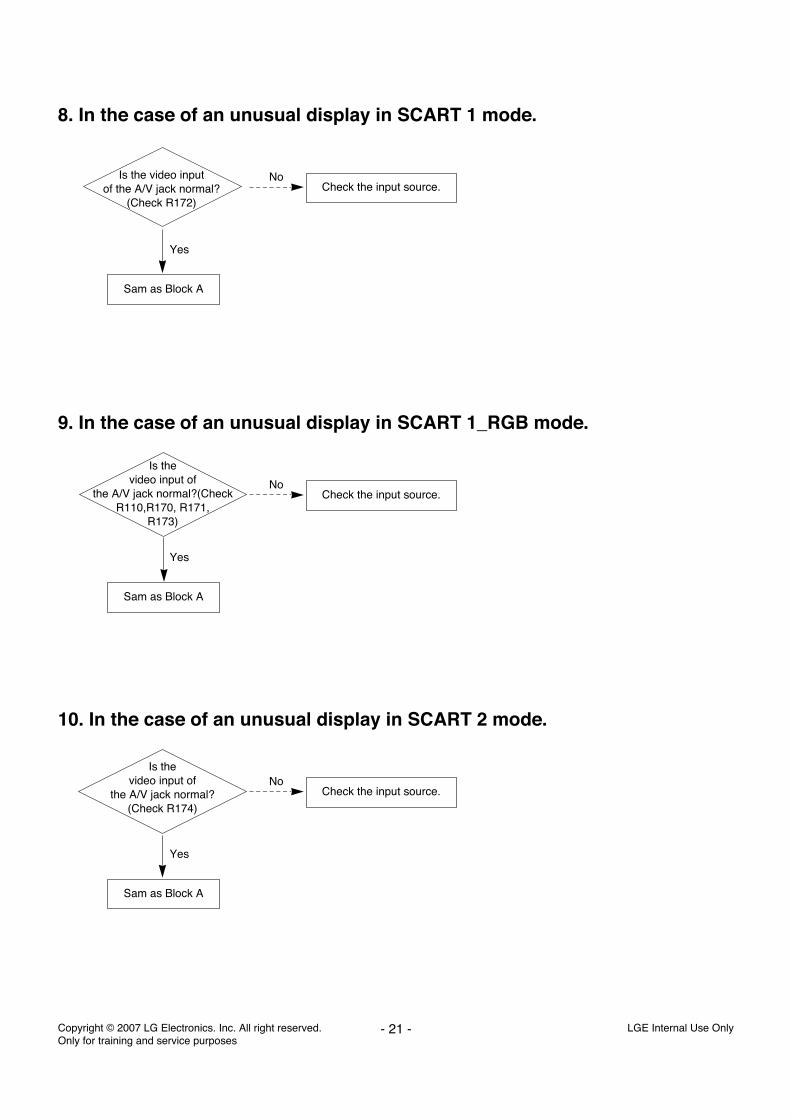
8. In the case of an unusual display in SCART 1 mode.
Is the video inputof the A/V jack normal?
(Check R172)
Yes
Sam as Block A
Check the input source.No
9. In the case of an unusual display in SCART 1_RGB mode.
Is thevideo input of
the A/V jack normal?(CheckR110,R170, R171,
R173)
Yes
Sam as Block A
Check the input source.No
10. In the case of an unusual display in SCART 2 mode.
Is thevideo input of
the A/V jack normal?(Check R174)
Yes
Sam as Block A
Check the input source.No

Copyright © 2007 LG Electronics. Inc. All right reserved. Only for training and service purposes
LGE Internal Use Only- 22 -
11. In the case of an unusual display in component 1 mode.
Is the videoinput of the A/V jack
normal? (Check R248,R249,R250)
Yes
Change the IC(IC500)
Check the input source.No
12. In the case of an unusual display in component 2 mode.
Yes
Change the IC(IC500)
Check the input source.No
Is the videoinput of the A/V Jk202normal? (Check R241,
R242, R243)
13. In the case of an unusual display in RGB mode.
Yes
Change the IC(IC500)
Check the input source.No
Is theR, G, B input
and H, V sync of the JK201normal?(Check R220, R221,
R253, R254,R255)
Copyright © 2007 LG Electronics. Inc. All right reserved. Only for training and service purposes
LGE Internal Use Only- 23 -
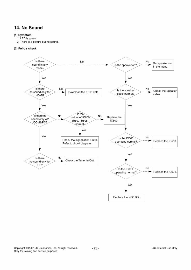
14. No Sound
(1) Symptom1) LED is green.2) There is a picture but no sound.
(2) Follow check
Is theresound in any
mode?Is the speaker on?
Yes Yes
Is the speakercable normal?
Yes
Yes
Is thereno sound only for
HDMI?
Yes
Is there no sound only AV/COM2/PC?
Is theoutput of IC600(R607, R608)
normal?
Yes
Is thereno sound only for
RF?
No
No
No
No
Download the EDID data.
Set speaker on in the menu.
No Replace theIC600.
No
Check the Speakercable.
No
Is the IC500operating normal? Replace the IC500.
No
Yes
Is the IC601operating normal? Replace the IC601.
Replace the VSC BD.
Yes
Check the signal after IC600.Refer to circuit diagram.
Check the Tuner In/Out.
No

Copyright © 2007 LG Electronics. Inc. All right reserved. Only for training and service purposes
LGE Internal Use Only- 24 -
15. HDMI mode
Is only videonormal?
Is only audionormal?
No
YesDownload EDID data each port.
Check the TMDS line wave.(R312~E3273)
1. Check the HDMI receiver’s status register. (0x60, offset 0x66)- If the value is 0xf or 0x8, it is normal.
2. Check the HDCP register. (0x6, offset 0x32)- Enable bit 6 : HDCP key loaded- Enable bit 5 : HDCP decryption active- Enable bit 4 : HDCP authentication attempted
Reset TMDS power down/ on register.- 0x60, offset 0x3f => 0xff
Check HDMI source. Change to another source or cable.
Yes
Is the wavecontinuous?
Normal video,Normal audio?
No
Yes
Replace the IC303.No
1. Check TV input mode.(HDMI 1 port support HDMI and DVI.So if you input DVI signal and PC audio fromphone jack, You can hear PC audio.)
2. Unplug and plug in the HDMI cable.(sometimes ESD surge occurred at HDMI port.)
3. Check the HDMI Mute register. (0x68, offset 0x37)4. Check the Audio-out channel mute register (0x68,
offset 0x32) is appropriately enabled.
Yes
Copyright © 2007 LG Electronics. Inc. All right reserved. Only for training and service purposes
LGE Internal Use Only- 25 -
HD
MI
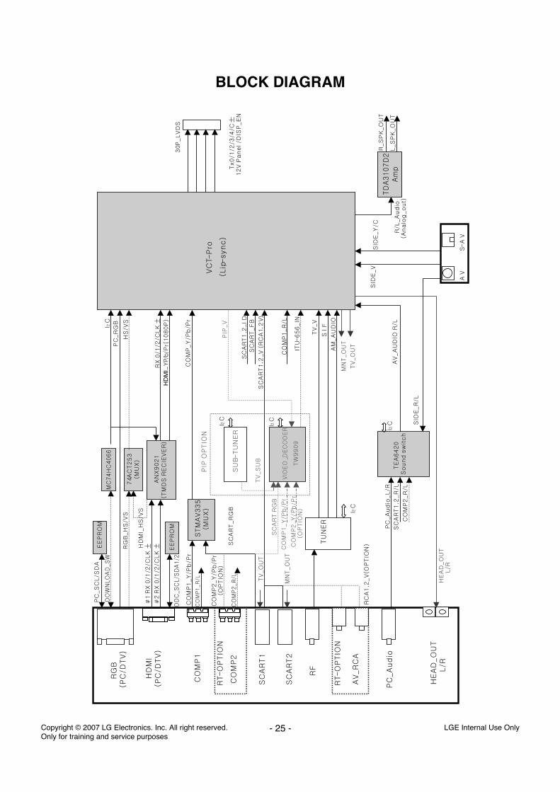
BLOCK DIAGRAM

Copyright © 2007 LG Electronics. Inc. All right reserved. Only for training and service purposes
LGE Internal Use Only- 26 -
430
600
301
300
200
591
590
120
530
580
520
400
230
240
250
260
220
210
EXPLODED VIEW

LGE Internal Use OnlyCopyright © 2007 LG Electronics. Inc. All right reserved. Only for training and service purposes

LGE Internal Use OnlyCopyright © 2007 LG Electronics. Inc. All right reserved. Only for training and service purposes

LGE Internal Use OnlyCopyright © 2007 LG Electronics. Inc. All right reserved. Only for training and service purposes

Dec., 2007Printed in KoreaP/NO : MFL36696902