Embed Size (px)
Citation preview
lg¥31Suburban AIRXCEL, INC. - SUBURBAN DIVISION 676 Broadway Street
Dayton, Tennessee 37321 423-775-2131
www.RVComfort.com
SUBURBAN GAS FURNACES INSTALLATION INSTRUCTIONS FOR MODEL~ SF-20Q • SF-25Q • SF-30Q • SF-35Q • SF-42Q
The design of the furnace has been listed for installation in recreational vehicles only. In order for the fu rnace to operate in conformity with generally accepted safety regulations, the installation instructions must be followed. Failure to comply with the installation instructions will void the warranty on the furnace and any responsibili ty on the part of AIRXCEL, INC. - SUBURBAN DIVISION.
The furnace was inspected before it left the factory. If any parts are found to be damaged , do not install the furnace. Immediately contact the transportation company and file a claim.
FOR YOUR SA FETY WHAT TO DO IF YOU SMELL GAS: • Extinguish any open flame. • Evacuate all persons from the vehicle. • Shut off the gas supply at t he gas container or
source. • Do not touch any electrical switch, or use any
phone or radio in the vehicle. • Do not start the vehicle's engine or electric
generator. • Contact the nearest gas supplier or qualified
service technician for repairs. • If you cannot reach a gas supplier or qualified
service technician, contact the nearest fi re department. Do not turn on the gas supply until the gas leak(s) has been repaired.
This book contains instructions covering the operation and maintenance of your furnace.
INSTALLER: LEAVE THIS MANUAL WITH THE APPLIANCE.
CONSUMER: RETAIN THIS MANUAL FOR FUTURE REFERENCE.
Should you require further information, contact your dealer or nearest Suburban Service Center.
FOR YOUR SAFETY DO NOT STORE OR USE GASOLINE OR OTHER FLAMMABLE VAPORS AND LIQUIDS IN THE VICINITY OF THIS OR ANY OTHER APPLIANCE.
WARNING! Improper installation, adjustment, alteration , service or maintenance can cause property damage, personal injury or loss of life. Refer to the installation instructions and/ or owners manual provided with this appliance. Installation and service must be performed by a qualified installer, service agency or the gas supplier.
WARNING! Be sure the furnace and all ignition systems are "OFF" during any type of refueling and while vehicle is in motion or being towed .
Part Number 204768 01-14-2014
INSTALLATION INSTRUCTIONS
WARNING! Installation of this appliance must be made in accordance with the written instructions provided in this manual. No agent, representative or employee of Suburban or other person has the authority to change, modify or waive any provision of the instructions contained in this manual.
THESE FURNACES ARE DESIGNED TO BE INSTALLED IN SUCH A MANNER THAT THEY CAN BE REMOVABLE FROM THE EXTERIOR OF THE RECREATIONAL VEHICLE.
IF UNIT IS TO BE INSTALLED VERTICALLY, YOU MUST USE KIT #520965 (INSTALLATION INSTRUCTIONS ARE ENCLOSED IN KIT) .
CAUTION: If possible, do not install the furnace to where the vent can be covered or obstructed when any door on the trailer is opened. If this is not possible, then the travel of the door must be restricted in order to provide a 6" minimum clearance between the furnace vent and any door whenever the door is opened.
NOTE: The exhaust temperature of this furnace could discolor or warp some materia ls. You should verify that the material used on the coach door, panel. or cover will not discolor or warp from the exhaust temperature whenever any door, panel, or cover is in the open position.
CAUTION: Due to the differences in vinyl siding, this appliance should not be installed on vinyl siding without first consulting with the manufacturer of the siding or cutting the siding away from the area around the appliance vent.
CAUTION: In any installation in which the vent of this appliance can be covered due to the construction of the RV or some special feature of the RV such as slide out, pop-up etc. always insure that the appliance cannot be operated by setting the thermostat to the positive " OFF" position and shutting off all electrical and gas supply to the appliance. Never operate furnace with vent covered.
CAUTION: This furnace was shipped from the factory set up for the gas connection to be made at the right rear of t he unit as illustrated in Figure 1. lfyou wish to make gas connection through the top of cabinet, you must remove furnace from cabinet and turn gas inlet fitting 90° CLOCKWISE. DO NOT TURN FITTING COUNTER-CLOCKWISE, this will loosen fitting and result in a gas leak.
WARNING! Hold manifold firmly when turning elbow to prevent any force from being inserted on the valve and to prevent any leaks from developing. Be sure to check all fittings for leaks including the inlet and outlet on the valve before reinsta ll ing furnace into cabinet. Correct all leaks immediately. NOTE: The furnace must be in operation to properly check for leaks.
NOTE: These furnaces must be installed and vented as described in th is manual so that the negative pressure created by the air circulating (return ai r) fan cannot affect the combustion air intake or venting of any other appliance. It is imperative that the products of combustion be properly vented to the atmosphere and that all combustion air supplied to burner be drawn from the outside atmosphere. (See Installing Vent Assembly.)
NOTE: Do not insta ll the furnace with the vent facing toward the forward end of the coach.
IMPORTANT: If this furnace is to be connected to a common duct system also serving a cooling unit, a manual or automatic damper is required to prevent any cold conditioned air from circu lating back into the fu rnace. Cold air passing over the furnace combustion chamber during the operation of the cooling unit can result in the formation of condensation inside the furnace combustion chamber. This condensation may promote corrosion and premature fai lure of the combustion chamber.
NOTE: These furnaces shall be installed so the electrical components are protected from water.
These furnaces are design certified for propane/LP gas only. Do not attempt to convert to natural gas.
Gas supply pressure for purposes of input adjustment:
Minimum - 11 " WC.* Maximum - 13" W C. *
(WC.* - Water Column).
In the U.S.A., the installation of the furnace must be in accordance with local codes and regulations. In the absence of local codes and regulations, refer to the latest edition of:
1. Standard for Recreational Vehicles NFPA 1192. 2. National Fuel Gas Code ANSI Z223.1 I NFPA 54. 3. Furnace must be electrically grounded in accordance with the latest edition of
the National Electrical Code NFPA 70. In Canada, the furnace must be installed in accordance with : 1. Standard CSA Z240.0.2-08 Recreational Vehicles. 2. CSA Standard Z240.6.2-08/C22.2 N0.148-08 Electrical Requirements for
Recreational Vehicles. 3. Standard Z240.4.2-08 Installation Requirements for Propane Appliances and
Equipment in Recreational Vehicles. 4. CAN/CGA-B149 Installation Codes. 5. Any applicable local codes and regulations.
This unit is equipped with an electric igniter device that has an energy consumption of .1amp@12 volts D.C .
WARNING! Extension tubes cannot be used. If you try to extend the vent, it wi ll result in improper installation which could cause unsafe furnace operation.
There are three (3) common methods described below for installing the furnace. Regardless of the method (see sections A. , B., or C. below) you choose, we require an opening be provided in the exterior of the trailer or motor home for free , unobstructed removal of the furnace. This exterior, removable panel or wall section of the trailer or motor home must be a minimum of 17-3/4 x 8.
It is important that adequate return air be provided to assure normal heating and operation of the furnace. Failure to provide the minimum return air will cause erratic furnace cycling. Refer to the chart shown below for minimum return air requirements.
Return Air Requirements Model Minimum Free (unobstructed) Area
SF-20/25/300 55 Sq. In.
SF-350 55 Sq. In.
SF-420 142 Sq. In.*
*May be reduced to 88 sq. in. min. if 5 ducts are used.
TABLE 1 NOTE: Return air must be from within the living area of the coach.
NOTE: RV's that have a wall of separation to a cargo area (Toy Box) to transport internal combustion engine vehicles must not have return air openings from this area.
A. INSTALLATION DIRECTLY AGAINST OUT ER PANEL OF COACH
(See Figure 1) (Panel supplied by installer)
Maximum wall thickness for this type installation is 2".
1. Locate the furnace near lengthwise center of the coach. 2. Choose a location for installation out of the way of wires, pipes, etc., which
might interfere with the installation. Adhere to the minimum clearances from the cabinet to combustible construction as listed in Table 2. Refer to Figure 3 for illustration of furnace clearances.
3. When an appliance is installed directly on carpeting, tile or other combustible material , other than wood flooring , the appliance shall be installed on a metal or wood panel extending the full width and depth of the appliance. If preferred , the carpeting, tile or combustible materials, other than wood may be cut away the full length and depth of the appliance plus the appliance minimum clearances to combustibles. (See Table 2.)
4. Cut an opening through the inner wall. This wil l allow the rear of the furnace to be installed against the outer panel of the coach.
5. Locate center lines for exhaust and intake, as shown in Figure 1. 6. Cut two 2-1 /4" diameter holes through the outer panel of the coach. (See
Figure 1.) 7. Put furnace in place, making sure that rear of the furnace cabinet is as close
to outer panel of the coach as possible and still assure proper vent tube overlap. (See Install ing Vent Assembly.)
8. Secure furnace to the floor using the two (2) holes provided in the furnace cabinet. (See Figure 4).
2
9. Be sure furnace is secured within furnace cabinet. (See Figure 4). 10. Install vent assembly. (See instructions for installing vent.)
B. INSTALLATION NOT AGAINST OUTER PANEL OR SKIN AND "X" DIMENSION GREATER THAN 1 '!."
(See Figure 2) (Exterior panel supplied by installer)
Maximum wall thickness for this type installation is 2" .
1. Locate the furnace near lengthwise center of the coach. 2. Choose a location for installation out of the way of wires, pipes, etc, which
might interfere with the installation. Adhere to the minimum clearances from cabinet to combustible construction as listed in Table 2. Refer to Figure 3 for illustration of furnace clearances.
3. When an appliance is installed directly on carpeting, tile or other combustible material, other than wood flooring , the appliance shall be installed on a metal or wood panel ex1ending the full width and depth of the appliance. If preferred, the carpeting , tile or combustible materials, other than wood may be cut away the full length and depth of the appliance plus the appliance minimum clearances to combustible. (See Table 2.)
4 Determine "X" dimension as shown in Figure 2. The tubes supplied with the furnace will accommodate an installation range for "X" from o-1 W' . If "X" dimension is greater than 1 W', then special vent tubes as charted in Figure 2 must be ordered.
WARNING! Do not alter, cut, or otherwise modify the vent tubes as supplied by Suburban. Doing so could result in inadequate intake of combustion air or improper venting of furnace exhaust.
5. After determining "X" dimension , complete the furnace installation as follows: 6. Locate center lines for exhaust and intake tubes as shown in Figure 1. 7. Cut two 2-3/4" diameter holes through the outer panel or outer skin. (See
Figure 2.) 8. Put furnace in place, making sure that rear of furnace cabinet is as close to
inner wall section of the coach as possible and still assure proper vent tube overlap. (See Installing Vent Assembly .)
9. Secure furnace to the floor using the two (2) holes provided in the furnace cabinet. (See Figure 4.)
10. Slide furnace into cabinet. Be sure furnace is secured within furnace cabinet (See Figure 4.)
11 . Install vent assembly. (See instructions for installing vent.)
C. INSTALLATION USING THE FURNACE ACCESS DOOR SUPPLIED BY SUBURBAN (See Figure 4)
Maximum wall thickness for this type installation is 2".
1. Locate the furnace near lengthwise center of coach. 2. Choose a location for installation out of the way of wires, pipes, etc. , which
might interfere with the installation. Adhere to the minimum clearances from the cabinet to combustible construction as listed in Table 2. Refer to Figure 3 for illustration of furnace clearances.
3. When an appliance is installed directly on carpeting, tile or other combustible material , other than wood flooring , the appliance shall be installed on a metal or wood panel extending the full width and depth of the appliance. If preferred , the carpeting, tile or combustible matters, other than wood may be cut away the full length and depth of the appliance plus the appliance minimum clearances to combustibles. (See Table 2.)
4. After furnace location has been determined , cut an opening 18-7/32 x 8-9/32" through the inner coach wall and the outer wall (skin) of the coach.
5. Caulk around opening as illustrated . Apply generously. The purpose of the caulking is to seal the back side of the door frame and the coach skin water tight.
6. Secure frame to outer wall (skin) through the holes in the frame. Screws should be used. (See Figure 4.) NOTE: Do not place screws into the holes required for mounting the door.
7. Slide furnace in place. The back of the furnace should be installed against or as close as possible to the flange on the door frame. (See illustration.) The furnace must maintain 1 /2" overlap on the intake and 1-1 /4" overlap on the exhaust.
8. Secure furnace to the floor using the two (2) holes provided in the furnace cabinet. (See Figure 4.)
9. Slide furnace into cabinet. Be sure furnace is secured within furnace cabinet. (See Figure 4.)
10. Position furnace access door over the frame. Secure the door to the coach skin . Be sure the coach skin is of sufficient strength to keep furnace access door in place and insure a tight seal. It may be necessary to build a wood or metal frame around the opening in order to provide adequate strength for securing door.
CAUTION: The screws provided with the door may not be of sufficient length and size for all applications and it may be necessary for the installer to substitute screws in order to adequately secure the furnace access door. 11. Install vent assembly. (See instructions for installing vent.)
Left Right Exhaust and Model Front Side Side Top Bottom Back Intake Tube
SF-20Q 1" O" O" O" O" O" 3/8"
SF-25Q 1" O" O" O" O" O" 3/8"
SF-30Q 1" O" O" O" O" O" 3/8"
SF-35Q 1" O" O" O" O" O" 3/8"
SF-42Q 1" 2" 2" 1" O" O" 3/8"
-NOTE-O" MEANS TO SPACER BUMPS
CLEARANCE FROM DUCTS TO COMBUSTIBLE MATERIAL - 1/4" (See Figure 3)
TABLE 2
INSTALLING VENT ASSEMBLY The vent outlet must be installed so it is in the same atmospheric pressure zone as the combustion air intake. The exhaust and intake tubes must be installed from the outside, pass through the RV skin and slide onto the furnace exhaust and intake.
WARNING! Do not alter the vent assembly supplied with th is furnace. Any modifications will result in improper installation which could cause unsafe furnace operation.
CAUTION! Combustion air must not be draw n from the living area. All air for combustion must be drawn from the outside atmosphere. All exhaust gases must be vented to the outside atmosphere - never inside the RV. Therefore, it is essential to insure that the vent cap and tube assemblies are properly installed. 1. Apply caulking to RV skin behind vent cap as shown in Figure 1. Apply caulking
generously around perimeter of vent cap and across center as shown. 2. Insert intake tube through RV skin and slide it onto the furnace intake (See
Figure 1.) Minimum tube overlap of 1/2" is required. 3. Insert vent cap exhaust tube through RV skin and slide it onto the furnace
exhaust (See Figure 1.) Minimum tube overlap of 1 1/4" is required. 4. Attach vent cap assembly to outer skin of RV with the six (6) screws provided. Do
not install vent assembly upside down. The word "Suburban" must be right side up.
CONNECTING GAS SUPPLY CAUTION: This furnace was shipped from the factory set up for the gas connection to be made at the right rear of t he unit as illustrated in Figure 1. If you wish to make gas connection through the top of cabinet, you must remove furnace from cabinet and turn gas inlet fittings 90° CLOCKWISE. DO NOT TURN FITTING COUNTER-CLOCKWISE, this will loosen fitting and result in a gas leak.
WARNING! Hold manifold firmly when turn ing elbow to prevent any force from being inserted on the valve and to prevent any leaks from developing. Be sure to check all fitting for leaks including the inlet and outlet on the valve before re installing furnace into cabinet. Correct all leaks immediately. NOTE: The furnace must be in operation to properly check for leaks.
Connect the gas supply to the furnace at the manifold , following the suggestions outlined below. It will be necessary to hold the flare fitting on the furnace manifold when connecting or loosening gas line.
NOTE: The compound used on threaded joints must be resistant to liquefied petroleum (LP) gas.
NOTE: The appliance must be disconnected from the gas supply piping system during any pressure testing of that system at test pressure in excess of 1 /2 PSIG.
The appliance must be isolated from the gas supply piping during any pressure testing of the gas supply piping system at test pressure equal to or less than 1/2 PSIG. 1. A 3/8" male flare connection is provided for gas line hookup. Some standards
may require the use of a manual shut off valve in the gas line external to the furnace cabinet.
2. In order to maintain a check of gas supplied pressure to the furnace , Suburban advises the installer to provide the 1/8" NPT plug tap for test gauge connection immediately upstream of the gas supply connection to the furnace and that it be readily accessible.
3. After the furnace has been connected to the gas supply , all joints must be checked for leaks.
WARNING! Never check for leaks with an open flame. Turn on the gas and apply soapy water to al l joints to see if bubbles are formed.
3
CONNECTING ELECTRICAL SUPPLY CAUTION: This furnace is designed for negative ground 12 volt D.C. system only. Do not attempt to alter the furnace for a positive ground system or connect the furnace directly to 115 volts A.C. Damage to furnace component parts will occur. Connect only to a protected circuit fused for not more than 20 amps.
Be sure all wiring to the furnace is of heavy enough gauge to keep the voltage drop through it to a minimum and to provide enough power for start-up surge. No. 12 gauge wire is recommended . If any of the original wire that is supplied with the appliance must be replaced, it must be replaced with type 105° C or its equivalent.
Power supply connections are to be on the right side of the furnace . The wires are color coded, red for positive (+) and yellow for negative (-). This polarity must be observed so the furnace motor will run the proper direction of rotation to insure correct air delivery. (See wiring diagram.)
If the furnace power supply is to be from a converter, we recommend that the converter system used to power the furnace be wired in parallel with the battery. This will serve two purposes:
1. Provide a constant voltage supply to the furnace. 2. Filter any A.G. spikes or volt surges.
CONNECTING DUCTS TO FURNACE The following duct requirements must be followed in order to assure proper operation of the furnace : A. The minimum open duct areas listed below must be maintained throughout
entire duct system including through register:
SIDE DUCTS TOP BOTTOM
DUCT DUCT MODEL
Min Open Min No Duct Min Open Min Open Duct Area Ducts Used Size Duct Area Duct Area
SF-20Q 25 SQ. IN . 2 4" 56 SQ. IN. 56 SQ. IN.
SF-25Q 36 SQ. IN. 3 4" 56 SQ. IN . 56 SQ. IN.
SF-30Q 36 SQ. IN . 3 4" 56 SQ. IN . 56 SQ. IN.
SF-35Q 48 SQ. IN. 4 4" 56 SQ. IN. 56 SQ. IN.
SF-42Q 48 SQ. IN. 4 4" 56 SQ. IN. *72 SQ. IN.
•SF-420 Bottom Duct requires use of Bottom Duct Kit, Part No. 520753
NOTE: Ducts terminating in a dead airspace (like holding tank compartments or cargo areas (Toy Boxes) with no means for return air recirculation should not be counted in the required duct area. Also ducts 2" in diameter or smaller should not be counted in the required duct area.
B. No outlet register is to be placed within 18" of the return air opening. Any register installed at 18" should never be toward the return air opening. If a register is installed on a wall 90 degrees to the return air, it can be less than 18".
C. Make the duct connections at the furnace cabinet tight. Loose connections will result in overheating of the component parts on the furnace and a reduction of the heated air flow through the duct system.
D. Avoid making any sharp turns in the flex duct system . Sharp turns will increase the static pressure in the plenum area and could cause the furnace to cycle.
E. Avoid making a lot of turns in the flex duct system. The straighter the duct system, the better the performance of the furnace .
F. When using flex duct, insure the duct is stretched and routed straight. Do not use longer length of flex duct than is needed to route directly from furnace to register. Do not allow the duct to kink or accumulate.
G. Maintain a minimum of 1/4" clearance where ducts pass through any combustible construction , such as coach cabinetry. (See Figure 3.) NOTE: UL listed duct materials can be O" clearance.
H. Do not install air boosters in the duct system. Such devices will cause the furnace to cycle on limit and to have erratic sail switch operation.
NOTE: After installation of the furnace and duct system is completed, adjustments must be made to obtain a temperature rise within the range specified on the Rating Plate.
INSTALLING THERMOSTAT The thermostat used with this unit must have NO voltage output to return leg when there is not a call for heat or in the "OFF" setting .
Locate the room thermostat approximately 4-1 /2 feet above the floor on an inside bulkhead where it is not affected by heat from any source except room air. Connect thermostat wiring to the blue wires on right side of furnace . (See wiring diagram.) If your furnace is equipped with a thermostat that has an adjustable anticipator, the anticipator should be set at . 7 amps. If you desire longer heating cycles, adjust the anticipator to a higher setting . If you desire shorter heating cycles , adjust the anticipator to a lower setting. Adjustments to the anticipator setting shou ld be made in .5 amp increments.
PREVENTIVE MAINTENANCE WARNING! If the user of this appliance fails to maintain it in the condition in which it was shipped from the factory or if the appliance is not used solely for its intended purpose or if appliance is not maintained in accordance with the instructions in this manual, then the risk of a fire and/or the production of carbon monoxide exisls which can cause personal injury, property damage or loss of life.
CAUTION: Label all wires before disconnecting for servicing. Proper polarity must be observed so the furnace motor will ru n with the proper direction of rotation to insure correct air delivery. (See wiring diagram).
CAUTION: Label all wires prior to disconnection when servicing controls. Wiring error can cause improper and dangerous furnace operation. Always verify proper operation of furnace after servicing.
Your furnace should be inspected by a qualified service agency yearly before turning the furnace on . Particular attention should be given to the following items.
1. Inspect furnace installation and vent termination to be sure furnace is properly secured in place (see Installation Instructions), that vent terminates to the atmosphere, and that vent tubes overlap properly (see Installing Vent Assembly.)
2. Inspect chamber and venting to assure that these components are physically sound without holes or excessive corrosion and that the installation and/ or re-installation is in accordance with Suburban's installation instructions. (Reference installation manual supplied with furnace.)
WARNING! It is imperative that the products of com bustion be properly vented to atmosphere and that all combustion air supplied to burner be drawn from outside atmosphere.
3. Check the base on which furnace is mounted. Be sure it is physically sound, void of any sagging , deterioration, etc.
4. Inspect furnace, the venting , ducting and gas piping to furnace for obvious signs of deterioration. Correct any defects at once.
5. Inspect combustion chamber for restrictions in exhaust or intake. It is imperative that the fiow of intake combustion air and the flow of exhaust gases being expelled to the outside atmosphere not be obstructed. Any soot or loose debris should be blown out using compressed air. (See Figure 7.)
6. Inspect all gaskets. If any gaskets show signs of leakage or deterioration, replace them. Safe operation of the furnace depends on all gaskets being tight.
7. Inspect return air inlet openings to the furnace. Remove any restrictions to assure adequate air fiow.
You, as the owner/user, should inspect the furnace monthly during the heating season for presence of soot on vent. Operating the furnace under this condition could lead to serious property damage, personal injury or loss of life. If soot is observed on the vent, immediately shut the furnace down and contact a qualified service agency. Listed below are several safety related items that you should follow during the heating season to assure continued safe operation of the furnace. 1. Inspect furnace venting. Venting must be free of obstructions, void of soot,
and properly terminated to the atmosphere. (See Installing Vent Assembly.)
WARNING! Do not install screens over the vent for any reason. Screens will become restricted and cause unsafe furnace operation. Accessories are being marketed for RV products which we do not recommend. For your safety, only factory authorized parts are to be used on your furnace.
2. Periodically inspect the vent for obstructions or presence of soot. Soot is formed whenever combustion is incomplete. This is your visual warning that the furnace is operating in an unsafe manner. If soot is present, immediately shut furnace down and contact your dealer or a qualified service person.
3. Keep furnace clean. More frequent cleaning may be required due to excessive lint from carpeting, bedding material, etc. It is imperative that control compartments, burners and circulating air passageways of the appliance be kept clean.
4. The motor is permanently lubricated and requires no oiling. 5. Keep the furnace area clear of any combustible materials, gasoline or other
flammable vapor and liquids. 6. Before operating furnace, check the location of the furnace vent to make sure it
will not be blocked by the opening of any door on the trailer. If it can be blocked, do not operate the furnace with the door open .
7. Do not restrict the flow of combustion air or the warm air circulation to the furnace. To do so could cause personal injury and/or death.
8. Never operate the furnace if you smell gas. Do not assume that the smell of gas is nonnal. Any time you detect the odor of gas, it is to be considered life threatening and corrected immediately. Extinguish any open flames including cigarettes and evacuate all persons from the vehicle. Shut off gas supply at LP gas bottle. (See safety notice on front cover of this manual.)
9. Immediately shut furnace down and call a service agency if furnace cycles erratically or delays on ignition.
WARNING! Should overheating occur, or the gas supply fa il to shut off, shut off the manual gas valve to the appliance before shutting off the electrical supply.
10. Never attempt to repair damaged parts. Always have them replaced by a qualified service agency.
11 . Never attempt to repair the furnace yourself. Seek the help of a qualified service person.
12. Never restrict the ducting installed by your trailer manufacturer. To do so could cause improper furnace operation .
4
13. Do not install air boosters in the duct system. Such devices will cause the furnace to cycle and to have erratic sail switch operation.
14. Clothing or other flammable material should not be placed on or near the appliance.
15. Always follow the operating instructions. Do not deviate from the step-by-step procedures.
16. Do not use this appliance if any part has been submerged under water. Immediately call a qualified service technician to inspect the appliance and to replace any part of the control system and any gas control that has been submerged under water.
17. When considering add-on rooms, porch or patio, attention must be given to the venting of your furnace. For your safety, do not terminate furnace vent inside add-on rooms, screen porch or onto patios. Doing so will result in products of combustion being vented into the room or occupied areas.
18. In any installation in which the vent of this appliance can be covered due to the construction of the RV or some special feature of the RV such as slide out, pop-up, etc. always insure that the appliance cannot be operated by setting the thermostat to the positive "OFF" position and shutting off all electrical and gas supply to the appliance. Never operate furnace with vent covered.
INSTALLATION AND REMOVAL OF UNIT INSTALLED FROM INSIDE
TO REMOVE 1. Disconnect power supply at furnace. 2. Remove vent cap assembly. 3. Disconnect gas connections. 4. Remove cabinet front (2 screws). 5. Remove tie-down screw from center of unit and remove furnace from cabinet.
TO INSTALL 1. Slide unit into cabinet. NOTE: Care must be taken in routing wiring to back of
cabinet and outside of cabinet. 2. Reinstall tie-down screw. 3. Reinstall cabinet front. 4. Connect gas line. 5. Check gas connections for leaks using a soap and water solution. Correct any
gas leaks immediately. 6. Reinstall vent cap assembly.
INSTALLATION AND REMOVAL OF UNIT WHEN OPTIONAL BACK IS USED
TO REMOVE 1. Break power to furnace. 2. Remove vent cap assembly. 3. Remove optional back. 4. Disconnect power supply at furnace. 5. Disconnect power supply plug from module board . 6. Disconnect electrode wire from module board. 7. Remove the two (2) screws securing module board and panel assembly to
firewall and pull out assembly. EXERCISE CARE NOTTO DAMAGE BOARD. NOTE: This will allow more room for making the gas connections at the flare fitt ing. It will be necessary to hold the flare fitting with a wrench when tightening or loosening the gas line. 8. Remove gas line. 9. Remove tie-down screw at blower base and remove furnace from cabinet.
TO REINSTALL 1. Slide unit into cabinet and secure with screw at base of blower. 2. Connect gas line. 3. Check gas connections for leaks using a soap and water solution. Correct any
gas leaks immediately. 4. Reinstall module board and panel assembly. 5. Reconnect electrode wire to board 6. Reconnect power supply to board. 7. Reconnect power to furnace. NOTE: If th is connection was made inside the
cabinet, care must be exercised to prevent wires from coming in contact with the room air blower wheel.
8. Reinstall optional back. 9. Reinstall vent cap. 10. Provide power to furnace.
OPERATING INSTRUCTIONS WARNING! Do not operate furnace while vehicle is in motion or being towed.
NOTE: During initia l firing of this furnace, a burn-off of excess paint and oils remaining from manufacturing process may cause "smoking" for 5 - 1 O minutes. 1. Stop! Read Users Information Manual supplied with furnace. 2. Turn the manual va lve (if so equipped) or the valve at the outside LP tank to
the "OFF" position. Do not force. 3. Set thermostat above room temperature to begin blower operation. A slight
delay will occur before the blower comes on . Allow blower to run for 5 minutes for combustion chamber purge cycle. If blower does not come on or stops before ignition cycle, go to shut down and contact your dealer or a local recreational vehicle service agency.
4. After 5 minutes, move thermostat lever below room temperature. Blower will remain on. Wait approximately 2 minutes for blower to go off.
5. Open manual shut-off valve (if so equipped) or the valve at the outside LP tank. Correct operating characteristics depend on the valve being positioned fully open. Never attempt to operate with a valve partially closed. NOTE: This furnace is equipped with a valve shut-off switch with switch in ' OFF" position. Gas will not flow to burner nor will the furnace operate.
6. Set thermostat lever to desired setting. If set above room temperature, blower will come on.
7. Allow 30 seconds for main burner to light after blower comes on. This furnace is equipped with an ignition device which automatically lights the burner. Do not try to light the burner by hand.
8. If burner does not light, repeat Steps 1 through 8. 9. If after three (3) attempts with no ignition, go to shut down and contact your
dealer or a local recreational vehicle service agency. Do not continue to cycle furnace through thermostat in an attempt to get ignition. NOTE: If furnace should lock out, the blower will go off in 5 minutes and remain off until unit is reset by reactivating thermostat.
TO SHUTDOWN 1. Set the thermostat to lowest setting, then move lever to ' OFF" position. 2. Turn manual shut off valve (if so equipped) to the ' OFF" position. Do not force .
ELECTRODE ADJUSTMENT For consistent ignition of the burner, it is important that the electrode be positioned properly over the top of the burner. The electrode was set at the factory for proper ignition and should not need further adjustment; however, if you should experience inconsistent ignition, reposition electrode as follows: Equipment needed: flashlight, black felt-tip pen, needle-nose pliers, measuring tape NOTE: Furnace must be removed. (See instructions for removing unit.)
1. Remove burner from combustion chamber by removing six (6) screws which attach the burner to the chamber and air baffles (plates).
2. Locate the lance in relation to the burner ports for electrode positioning by: a. Shine a flashlight into the burner venturi as illustrated. (Be sure flashlight
lens is against the end of the burner.) b. Light will reflect off the lance in the venturi of the burner and sh ine through
a portion of the two (2) rolls of burner ports in the top of the burner. c. Using a black felt-tip pen, mark a line along top of burner 3/16' in back of
the lance and parallel with lance. Make an additional mark indicating the center line of the lance. (See illustration.) Both marks will be used later as reference marks; therefore, keep lines thin .
3. Reassemble the burner. 4. Adjust electrode so the electrode probe is positioned along the marked center
line of the burner lance and the tip of the electrode terminates 3/16" from the back of the lance. (At the line marked in Step 2-c.) (See Figure 5.)
5. IMPORTANT: Be sure electrode probe maintains a 1/8" spark gap over the burner as illustrated.
6. Reinstall the furnace into the cabinet following the instructions in the manual.
PARTS AND SERVICE Contact a conveniently located recommended Suburban Service Center. Describe to them the nature of your problem, make an appointment, if necessary, and provide for delivery of your RV with the appliance installed.
To obtain information on locating a local service agency, contact: AIRXCEL, Inc., Suburban Division Customer Service Department 676 Broadway Street Dayton, TN 37321 (423) 775-2131 Ext. 7101 www.RVComfort.com
5
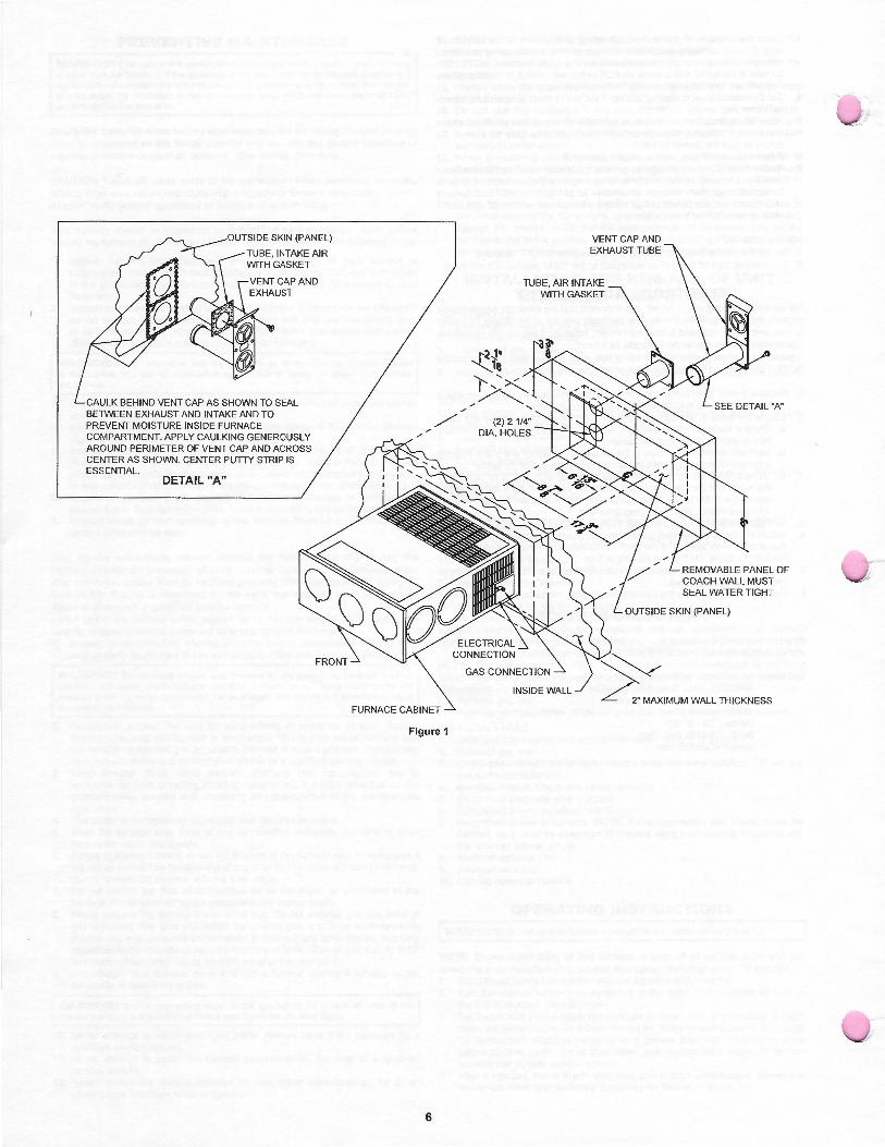
CAULK BEHIND VENT CAP AS SHOWN TO SEAL BETWEEN EXHAUST AND INTAKE AND TO PREVENT MOISTURE INSIDE FURNACE COMPARTMENT. APPLY CAULKING GENEROUSLY AROUND PERIMETER OF VENT CAP AND ACROSS CENTER AS SHOWN. CENTER PUTTY STRIP IS ESSENTIAL.
DETAIL "A"
FURNACE CABINET
Figure 1
6
VENT CAP AND EXHAUST TUBE
TUBE, AIR INTAKE WITH GASKET
REMOVABLE PANEL OF COACH WALL MUST SEAL WATER TIGHT
OUTSIDE SKIN (PANEL)
INSIDE WALL ~•MUM WACC '"'C'""
MOUNTING SURFACE
-j 1"
" DIMENSION EXTENSION TUBES KIT NO. * USE VENT SUPPLIED WITH FURNACE
051249 520768 520968 520551
~INTAKE: 1/2" MINIMUM OVERLAP ~EXHAUST: 1 1/4" MINIMUM OVERLAP
VENT CAP
~NEVER INSTALL THE EXHAUST TUBE WITH LESS THAN 1 1/4" OVERLAP, OR THE INTAKE TUBE WITH LESS THAN 1/2" OVERLAP. * STANDARD VENT ASSEMBLY FURNISHED WITH FURNACE. SPECIAL EXTENSION TUBES, IF NEEDED, MUST BE ORDERED SEPARATELY. EXTENSION KITS COME WITH COMPLETE INSTALLATION INSTRUCTIONS.
Figure 2
*OPENING FOR RETURN AIR
*OPENING FOR RETURN AIR
O" TO SPACER
<.___ O" TO SPACER
MAINTAIN A 1/4" INCH CLEARANCE WHERE DUCTS PASS THROUGH A CABINET WALL. UL LISTED DUCT MATERIALS CAN BE O" CLEARANCE.
r--*--THE-ToTAL~-FR_E_E~-uNo-ssrRu_c_-fE-DR-EruR_N_AIR-oP"ENING--l ! TO THE FURNACE MUST NOT BE LESS THAN THE MINIMUM i i SPECIFIED IN TABLE 1. ! \, _____________________________________________________________________________________ ,
Figure 3
7
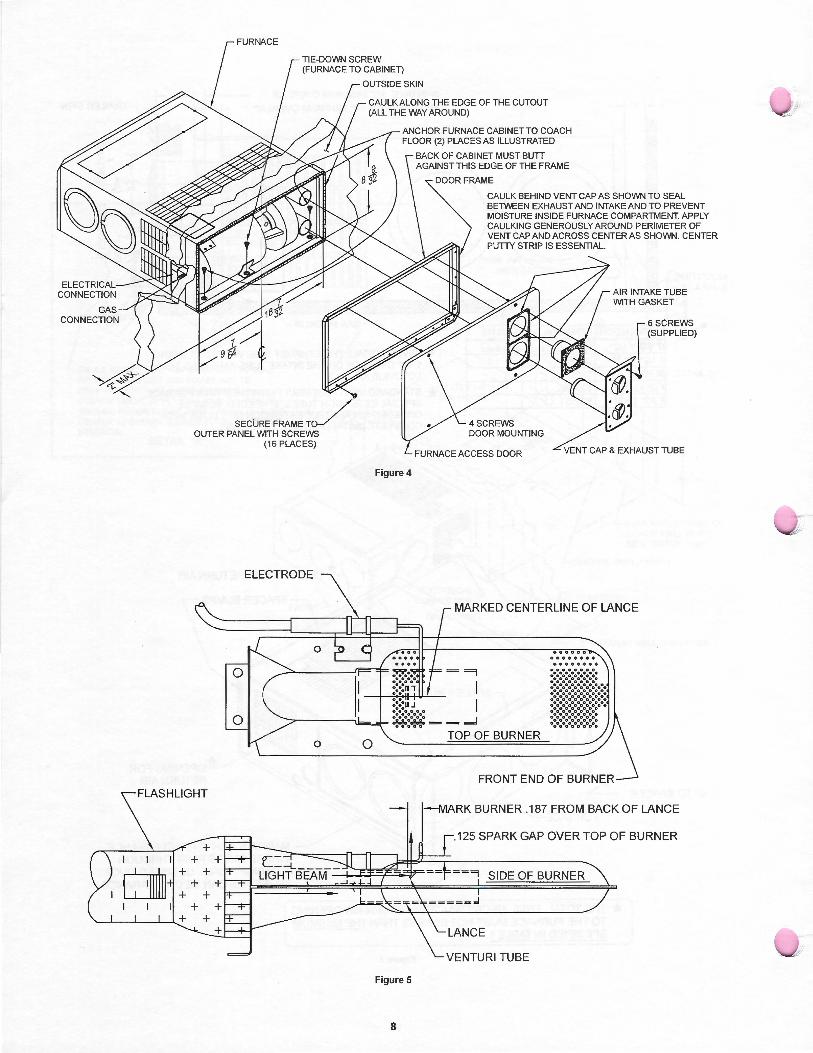
I
~
SECURE FRAME T/ OUTER PANEL WITH SCREWS
+ + + +
+ + + +
+ +
(16 PLACES)
ELECTRODE
0
~~~~~~~+ + +
OUTSIDE SKIN
CAULK ALONG THE EDGE OF THE CUTOUT (ALL THE WAY AROUND)
ANCHOR FURNACE CABINET TO COACH FLOOR (2) PLACES AS ILLUSTRATED
Figure 4
Figure 5
8
BACK OF CABINET MUST BUTT AGAINST THIS EDGE OF THE FRAME
DOOR FRAME
CAULK BEHIND VENT CAP AS SHOWN TO SEAL BETWEEN EXHAUST AND INTAKE AND TO PREVENT MOISTURE INSIDE FURNACE COMPARTMENT. APPLY CAULKING GENEROUSLY AROUND PERIMETER OF VENT CAP AND ACROSS CENTER AS SHOWN. CENTER PUTTY STRIP IS ESSENTIAL.
FURNACE ACCESS DOOR VENT CAP & EXHAUST TUBE
MARKED CENTERLINE OF LANCE
TOP OF BURNER
00000000 00000000
i~~~!j!i~~!ti11 ·:·:·:·:·:·:·:·:
FRONT END OF BURNER
j--MARK BURNER .187 FROM BACK OF LANCE
I r-125 SPARK GAP OVER TOP OF BURNER
SIDE OF BURNER
VENTURI TUBE
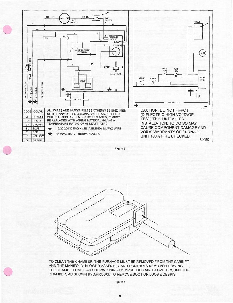
BL
R
u z J: g ;:: "' w '.'; :S
~ ~ "' "' 0 u 0 ::; ::; a:: 0 a:: w > w J: N J: >- >-
+ ~ ~ ID a:: ID
CODE COLOR
0 ORANGE
BK BLACK
BR BROWN
BL BLUE
R RED y YELLOW
G GREEN
+w
BL BK
y BR
ELECTRODE
*R
ALL WIRES ARE 18 AWG UNLESS OTHERWISE SPECIFIED NOTE: IF ANY OF THE ORIGINAL WIRES AS SUPPLIED WITH THE APPLIANCE MUST BE REPLACED, IT MUST BE REPLACED WITH WIRING MATERIAL HAVING A TEMPERATURE RATING OF AT LEAST 105° C.
• 16/30 200°C RADIX (SIL-A-BLEND) 18 AWG WIRE * 14 AWG 105°C THERMOPLASTIC
Figure 6
+
LIMIT SAIL SW. SW.
VALVE rsTAT
SW~
12VOLTS D.C
CAUTION: DO NOT HI-POT (DIELECTRIC HIGH VOLTAGE TEST) THIS UNIT AFTER INSTALLATION. TO DO SO MAY CAUSE COMPONENT DAMAGEAND VOIDS WARRANTY OF FURNACE. UNIT 100% FIRE CHECKED.
340501
TO CLEAN THE CHAMBER, THE FURNACE MUST BE REMOVED FROM THE CABINET AND THE MANIFOLD. BLOWER ASSEMBLY AND CONTROLS REMOVED LEAVING THE CHAMBER ONLY, AS SHOWN. USING COMPRESSED AIR, BLOW THROUGH THE CHAMBER, AS SHOWN BY ARROWS, TO REMOVE SOOT OR LOOSE DEBRIS.
Figure 7
9
TWO YEAR LIMITED WARRANTY SUBURBAN RECREATIONAL VEHICLE FURNACE
TWO YEAR LIMITED WARRANTY This Suburban product is warranted to the original purchaser to be free from defects in material and workmanship under normal use and maintenance for a period of two years from date of purchase whether or not actual use begins on that date. It is the responsibility of the consumer/owner to establish the warranty period. Suburban does not use warranty registration cards for its standard warranty. You are required to furnish proof of purchase date through a Bill of Sale or other payment records.
Suburban will replace any parts that are found defective within the first two years and will pay a warranty service allowance directly to the recommended Suburban Service Center at rates mutually agreed upon between Suburban and its recommended service centers. Replacement parts will be shipped FOB the shipping point within the Continental United States, Alaska and Canada to the recommended service center performing such repairs. All freight, shipping and delivery cost shall be the responsibility of the owner. The exchanged part or unit will be warranted for only the unexpired portion of the original warranty. Before having warranty repairs made confirm that the service agency is a recommended service center for Suburban. DO NOT PAY THE SERVICE AGENCY FOR WARRANTY REPAIRS; SUCH PAYMENTS WILL NOT BE REIMBURSED.
Suburban reserves the right to examine the alleged defect in the furnace or component parts, and it is the owner's obligation to return the furnace and/or component parts to Suburban or its representative . When returning a furnace, it must include all component parts and the serial number plate. Returned component parts must be individually tagged and identified with the furnace's model number, serial number and date of installation.
For warranty service, the owner/user should contact the nearest recommended Suburban Service Center, advising them of the model and serial numbers (located on the furnace) and the nature of the defect. Transportation of the RV to and from the Service Center and/or travel expenses of the Service Center to your location is the responsibility of the owner/user. A current listing of recommended service centers may be obtained from Suburban's website, www.rvcomfort.com. If you cannot locate a recommended service center locally, the service agency chosen to perform warranty repairs must contact our Service Department at 423-775-2131 for authorization before making repairs. Unauthorized repairs made will not be paid by Suburban.
THREE YEAR LIMITED WARRANTY ON HEAT EXCHANGER The furnace heat exchanger is further warranted to be free from defects in material and workmanship during the third through fifth year after the date of original purchase. A replacement heat exchanger will be provided under the same conditions as stated in the two year warranty EXCEPT no labor reimbursement will be provided.
LIMITATION OF WARRANTIES ALL IMPLIED WARRANTIES (INCLUDING IMPLIED WARRANTIES OF MERCHANTABILITY) ARE HEREBY LIMITED IN DURATION TO THE PERIOD FOR WHICH EACH LIMITED WARRANTY IS GIVEN. SOME STATES DO NOT ALLOW LIMITATIONS ON HOW LONG AN IMPLIED WARRANTY LASTS SO THE ABOVE LIMITATIONS MAY NOT APPLY TO YOU . THE EXPRESSED WARRANTIES MADE IN THIS WARRANTY ARE EXCLUSIVE AND MAY NOT BE ALTERED, ENLARGED, OR CHANGED BY ANY DISTRIBUTOR, DEALER OR OTHER PERSON WHOMSOEVER.
SUBURBAN WILL NOT BE RESPONSIBLE FOR: 1. Normal maintenance as outlined in the installation , operating and service instructions owner's manual including cleaning of component parts; such as, orifices and
burners.
2. Initial checkouts and subsequent checkouts which indicate the furnace is operating properly, or diagnosis without repair.
3. Damage or repairs required as a consequence of faulty or incorrect installation or application not in conformance with Suburban instructions.
4. Failure to start and/or operate due to loose or disconnected wires; water or dirt in controls, fuel lines and gas tanks; restriction or alteration of return air circulation ; low voltage.
5. Routine adjustments that may be required to the thermostat, electrode and burner.
6. Costs incurred in gaining access to the furnace.
7. Parts or accessories not supplied by Suburban .
8. Freight charges incurred from parts replacements .
9. Damage or repairs needed as a consequence of any misapplication, abuse, unreasonable use, unauthorized alteration, improper service, improper operation or failure to provide reasonable and necessary maintenance.
10. Suburban products whose serial number has been altered, defaced or removed.
11. Suburban products installed or warranty claims originating outside the Continental U.S.A., Alaska, Hawaii and Canada.
12. Damage as a result offloods, winds, lightning, accidents, corrosive atmosphere or other conditions beyond the control of Suburban .
13. ANY SPECIAL, INDIRECT OR CONSEQUENTIAL PROPERTY, ECONOMIC OR COMMERCIAL DAMAGE OF ANY NATURE WHATSOEVER.
Some states do not allow the exclusion of incidental or consequential damages, so the above limitation may not apply to you .
NO REPRESENTATIVE, DEALER, RECOMMENDED SERVICE CENTER OR OTHER PERSON IS AUTHORIZED TO ASSUME FOR SUBURBAN MANUFACTURING COMPANY ANY ADDITIONAL, DIFFERENT OR OTHER LIABILITY IN CONNECTION WITH THE SALE OF THIS SUBURBAN PRODUCT.
This warranty gives you specific legal rights, and you may also have other rights wh ich vary from state to state.
IF YOU HAVE A PRODUCT PROBLEM
FIRST:
If your RV has its original furnace and is still under the RV manufacturer's warranty, follow the steps suggested by your dealer or manufacturer of the RV.
SECOND:
Contact a conveniently located recommended Suburban Service Center. Describe to them the nature of your problem, make an appointment, if necessary, and provide for delivery of your RV to the selected service center.
THIRD:
For the location of the nearest service center, refer to the listing provided or contact:
Suburban Manufacturing Company
Customer Service Department
676 Broadway Street
Dayton , Tennessee 37321
(423) 775-2131 , Ext. 7101
www.RVComfort.com
FOR FUTURE REFERENCE, YOU SHOULD RECORD THE FOLLOWING INFORMATION:
MODEL NUMBER:
SERIAL NUMBER:
STOCK NUMBER:
DATE OF PURCHASE:
ICl§ISuburban
IC#31Suburban
OPTIONAL EXTENDED COVERAGE PLANS LIMITED EXTENDED FURNACE HEAT EXCHANGER WARRANTY (OPTIONAL ALL MODELS)
676 Broadway Street Dayton, Tennessee 37321
423-775-2131 www.RVComfort.com
Please note the standard warranty on your Suburban recreational vehicle furnace as described on the back page of your owners manual. An additional EXTENDED LIMITED FURNACE HEAT EXCHANGER WARRANTY may be purchased which:
1. Warrants the heat exchanger to be free from defects in material and workmanship through the seventh year after the date of original purchase. (The standard warranty provides 5 year coverage.)
2. Provides a labor allowance to a recommended Suburban service center at rates mutually agreed upon between Suburban and its recommended service centers for in-warranty furnace heat exchanger replacement during this 7 year period. (The standard warranty covers labor only during the first two years.)
The cost for this extended coverage plan on the fu rnace heat exchanger is $25.00.
OPTIONAL TRAVEL MILEAGE COVERAGE - (PARK MODELS ONLY) The Limited Warranty provided with your Suburban recreational vehicle furnace specifically excludes any coverage for travel expenses by the servicing agency. The reason for this is that in most cases the recreational vehicle can be taken to the servicing agency for diagnosis and repair. This is not practical with park model units, therefore, you may want to consider the optional travel mileage coverage available at a price of $25.00. This Extended Warranty is only available on furnaces whose model number begins with the letter "P". This optional travel mileage coverage will pay up to 250 miles of service travel for a recommended Suburban Service Center representative to travel to your location to provide in-warranty service on your Suburban furnace. The compensation rate is fixed at 25 cents per mile. Service Center charges in excess of 250 miles and/or 25 cents per mile remain your obligation. This optional travel mileage coverage is effective for two years from date of purchase.
Either (or both) the extended and optional coverage plans must be purchased within 90 days of the date the new furnace or new recreational vehicle is purchased. The standard warranty and these extended/optional coverage plans will commence on the furnace or recreational vehicle purchase date and apply only to the original purchaser. WARRANTY ADMINISTRATION, EXCLUSIO SAND LIMITATIONS ARE THE SAME AS DESCRIBED IN THE STANDARD WARRANTY.
NOTE: Neither of the above plans are transferable. They apply only to the original owner. No refunds, prorated or otherwise will be provided after warranty has been in effect for 30 days
CUT ALONG DOTTED LINE - RETURN THIS PORTION
Furnace Model Number: Furnace Serial Number:
This information is listed on a serial plate or sticker located just inside the front cover of your heating unit.
Extended/Optional Coverage Plans I wish to purchase:
Limited Extended Furnace heater Exchanger Warranty (All Furnaces) _____ $25.00
Park Model Travel Mileage Coverage (Model Number begins with "P") _____ $25.00
Name:
Street
City: State: Zip: Phone:
RV Coach Mfg. Name: RV Coach Model Number: ---------------------- ---------------------RV Coach ID Number: RV or Furnace Purchase Date:
Signature:
All blanks must be filled in or warranty will not be validated. After receipt of this information and your payment, Suburban will provide you with written confirmation for your records. Return card and check to: SUBURBAN MANUFACTURING COMPANY
676 Broadway Street Dayton, TN 37321
• Please print legibly, your name and return address below. This will be your returned acknowledgmenl
201406 6/00
NAME:
ADDRESS:
CITY:
STATE: ZIP: