Embed Size (px)
Citation preview

LIBRETTO ISTRUZIONIUSER HANDBOOK
Istruzioni originali - Translation of the original instruction


3
ITALIA
NO
PRESCRIZIONI DISICUREZZAIl presente libretto costituisce parte integrante ed essenziale del prodotto e dovrà essere consegnato all’utilizzato-re. Leggere attentamente le avvertenze contenute nel presente libretto in quan-to forniscono importanti indicazioni riguardanti la sicurezza di installazione, d’uso e manutenzione. Conservare con cura questo libretto per ogni ulteriore consultazione.
Dopo aver tolto l’imballaggio assicurar-si dell’integrità dell’apparecchio. In caso di dubbio non utilizzare l’apparec-chio e rivolgersi a personale professio-nalmente qualificato. Gli elementi dell’imballaggio (sacchetti in plastica, polistirolo espanso, chiodi, ecc..) non devono essere lasciati alla portata dei bambini in quanto potenziali fonti di pericolo, né essere dispersi nell’am-biente.
PERICOLO DI INQUINAMENTO
La macchina è adatta per essere instal-lata in ambienti quali locali di servizio per il personale presso negozi, uffici e altri ambienti di lavoro, in agriturismi, presso gli spazi per clienti in hotels, motels, bed and breakfast e altri ambiti residenziali.
Prima di collegare l’apparecchio accer-tarsi che i dati di targa siano rispondenti a quelli della rete di distribuzione elettri-ca. La targa è visibile all'interno della macchina rimuovendo la vaschetta rac-cogli acque.La macchina deve essere installata secondo le norme (codici) applicabili federali, statali e locali in vigore per gli impianti idraulici che comprendono dispositivi antiriflusso. Per questo moti-vo, i collegamenti idraulici devono esse-re eseguiti da un tecnico qualificato. La garanzia decade nel caso in cui le carat-teristiche dell'alimentazione elettrica non siano corrispondenti ai dati di targa.
Il costruttore non può essere considera-to responsabile per eventuali danni cau-sati dalla mancanza di messa a terra dell’impianto. Per la sicurezza elettrica di questo apparecchio è obbligatorio predisporre l’impianto di messa a terra, rivolgendosi ad un elettricista munito di patentino, che dovrà verificare che la portata elettrica dell’impianto sia ade-guata alla potenza massima dell’appa-recchio indicata in targa.
L'elettricista munito di patentino dovrà anche accertare che la sezione dei cavi dell’impianto sia idonea alla potenza assorbita dall’apparecchio.
È vietato l’uso di adattatori, prese multiple e prolunghe. Qualora il loro uso si rendes-se indispensabile è necessario chiamare un elettricista munito di patentino.
Durante l'installazione del dispositivo devono essere utilizzati i componenti e i materiali in dotazione al dispositivo stesso. Qualora fosse necessario l'utiliz-zo di altra componentistica, l'installatore deve verificare l'idoneità dello stesso ad essere utilizzato a contatto con l'acqua per consumo umano.L'installatore deve eseguire i collega-menti idraulici rispettando le norme di igiene e sicurezza idraulica di tutela ambientale vigenti nel luogo di installa-zione. Quindi per l’impianto idraulico rivolgersi ad un tecnico autorizzato. Per l'eventuale collegamento alla rete idrica utilizzare sempre un tubo nuovo in dota-zione, i tubi vecchi non devono essere utilizzati.
L'alimentazione del dispositivo deve essere effettuata con acqua idonea al consumo umano conforme alle disposi-zioni vigenti nel luogo di installazione. L'installatore deve acquisire dal proprie-tario/gestore dell'impianto conferma che l'acqua rispetti i requisiti sopra indicati.
Questo apparecchio dovrà essere desti-nato solo all’uso descritto in questo manuale. Il costruttore non può essere considerato responsabile per eventuali danni causati da usi impropri, erronei ed irragionevoli.

4
ITA
LIA
NO
L’apparecchio non è idoneo per l’utilizzo da parte dei bambini, persone con ridot-te capacità fisiche, sensoriali o mentali, o carenti di conoscenze a meno che non sia data supervisione o istruzione. I bambini non devono giocare con l'appa-recchio. Pulizia e manutenzione non devono essere fatte da bambini senza supervisione.
Questo apparecchio è destinato ad un uso professionale.
La temperatura di funzionamento deve essere compresa nel range [+5, +35]°C.Al termine dell'installazione, il dispositi-vo viene attivato e portato fino alla con-dizione nominale di lavoro lasciandolo in condizioni di “pronto al funzionamento”.Dopo il raggiungimento dello stato di “pronto al funzionamento” si effettuano le seguenti erogazioni:
-rogatore caffè (per più erogatori si divida in uguale misura);
Al termine dell'installazione sarebbe buona regola stilare un rapporto di quanto effettuato.
ATTENZIONE
Prima di utilizzare la macchina leggere interamente il manuale d’uso o quanto-meno le prescrizioni di sicurezza e la messa a punto.
L’uso di un qualsiasi apparecchio elettri-co comporta l’osservanza di alcune regole fondamentali.In particolare:
mani o piedi bagnati;
nudi;
adibiti a bagno o doccia;-
ne, per scollegare l’apparecchio dalla rete di alimentazione;
-chio ad agenti atmosferici (piog-gia, sole, ecc..);
sia usato da bambini, o da perso-nale non autorizzato e che non abbia letto e ben compreso que-sto manuale.
Il tecnico autorizzato deve, prima di effettuare qualsiasi operazione di manu-tenzione, spegnere l’interruttore della macchina e staccare la spina.
OKPer le operazioni di pulizia portare la macchina a stato energetico “O”, cioè “INTERRUTTORE MACCHINA SPENTO E SPINA STACCATA” ed attenersi esclu-sivamente a quanto previsto nel presen-te libretto.
Per Pulizia e manutenzione periodica fare riferimento ai capitoli 6 e 7.
OKIn caso di guasto o di cattivo funziona-mento dell’apparecchio, spegnerlo. È severamente vietato intervenire. Rivolgersi esclusivamente a personale professionalmente qualificato. L’eventuale riparazione dei prodotti dovrà essere effettuata solamente dalla casa costruttrice o da centro di assi-stenza autorizzato utilizzando esclusiva-mente ricambi originali.Il mancato rispetto di quanto sopra può compromettere la sicurezza dell’appa-recchio.

5
ITALIA
NO
Durante l’uso della lancia del vapore, prestare molta attenzione e non mettere le mani sotto di esso e non toccarla subito dopo l’uso.
Ricordare che prima di effettuare qualsi-asi operazione di installazione, manu-tenzione, scarico, regolazione, l’opera-tore qualificato deve indossare i guanti da lavoro e le scarpe antinfortunistiche.
L’operatore nel momento dell’aggiunta del caffè, non deve mettere le mani all’interno del contenitore.Il livello sonoro della macchina è inferio-
Nel caso di macchina con connessione idrica alla rete la pressione minimo deve essere 2 bar ed inoltre la pressione mas-sima per il corretto funzionamento della macchina non deve superare il 4 bar.
ATTENZIONE
INFORMAZIONE AGLI UTENTI
Decreto Legislativo 25
“Attuazione delle Direttive
riduzione dell’ uso di sostanze pericolo-se nelle apparecchiature elettriche ed elettroniche, nonché allo smaltimento dei rifiuti”.
Il simbolo del cassonetto barrato riportato sull’apparecchiatura indica che il prodotto alla fine della propria vita utile deve essere raccolto separatamente dagli altri rifiuti. L’ utente dovrà, pertanto, conferire l’ apparec-chiatura giunta a fine vita agli idonei centri di raccolta differenziata dei rifiuti elettronici
PERICOLO DI INQUINAMENTO
Non disperdere la macchina nell’ambien-te: per lo smaltimento rivolgersi ad un centro autorizzato o contattare il costrut-tore che darà indicazioni in merito.
PERICOLO DI INTOSSICAZIONE
Una volta iniziato il lavaggio della mac-china, non interromperlo, possono rima-nere dei residui di detergente all’interno del gruppo erogazione.
PERICOLO DI USTIONE
Per favorire l’areazione della macchina
macchine dalla parte dell’areazione.
All’installazione, l’elettricista munito di patentino dovrà prevedere un interrutto-re onnipolare come previsto dalle nor-mative di sicurezza vigenti con distanza di apertura dei contratti e che consenta la disconnessione completa nelle condi-zioni della categoria di sovratensione III.
Per evitare surriscaldamenti pericolosi si raccomanda di svolgere per tutta la sua lunghezza il cavo di alimentazione.Non ostruire le griglie di aspirazione e/o di dissipazione in particolare dello scal-datazze.
Il cavo di alimentazione di questo appa-recchio non deve essere sostituito dall’utente. In caso di danneggiamento, spegnere l’apparecchio e per la sua sostituzione rivolgersi esclusivamente a personale professionalmente qualificato.
In caso di necessità di sostituzione del cavo di alimentazione questa può esse-re eseguita solo da un centro assistenza autorizzato o dal costruttore.
Allorché si decida di non utilizzare più un apparecchio di questo tipo si racco-manda di renderlo inoperante dopo aver staccato la spina, tagliare il cavo di ali-mentazione.

6
ITA
LIA
NO IDENTIFICAZIONE
MACCHINA
Per qualsiasi comunicazione con il costruttore Nuova Simonelli, citare sempre il numero di matricola della macchina.
La macchina viene trasportata in pallett con più macchine dentro scatoloni assicurati al pallett con delle centine.Prima di procedere a qualsiasi operazione di trasporto o movimentazione, l’operatore deve:
indossare guanti e scarpe antinfortunistici ed una tuta con elastici alle estremità.
Il trasporto del pallett deve essere effettuato con un mezzo di sollevamento adeguato (tipo muletto).
ATTENZIONE
PERICOLO DI URTO O SCHIACCIAMENTO
cm da terra e raggiungere la zona di carico. Dopo aver verificato che non ci siano ostacoli, cose o persone, proce-dere al carico.Una volta arrivati a destinazione, sempre con un mezzo di sollevamento adeguato (es. muletto), dopo essersi assicurati che non ci siano cose o persone nell’a-rea di scarico, portare il pallett a terra e
all’area di immagazzinamento.
ed elettrotecnici, oppure riconsegnarla al rivenditore al momento dell’acquisto di una nuova apparecchiatura di tipo equivalente, in ragione di uno a uno. L’ adeguata raccolta differenziata per l’ avvio successivo dell’ apparecchiatura dimessa al riciclaggio,al trattamento e allo smaltimento ambientalmente compatibile contribuisce ad evitare possibili effetti nega-tivi sull’ ambiente e sulla salute e favorisce il riciclo dei materiali di cui è composta l’ apparecchiatura. Lo smaltimento abusivo del prodotto da parte dell’ utente comporta l’ applicazione delle sanzioni amministrative di cui al D.Lgs.n.22/1997” (articolo 50 e seguenti del D.Lgs.n.22/1997).
ATTENZIONE
PERICOLO DI URTO O SCHIACCIAMENTO
Prima della seguente operazione verifi-care che il carico sia a posto e che con il taglio delle centine non cada.L’operatore con guanti e scarpe antin-fortunistiche, deve procedere al taglio delle centine e allo stoccaggio del pro-dotto, in questa operazione consultare le caratteristiche tecniche del prodotto per vedere il peso della macchina da immagazzinare e potersi regolare di conseguenza.
PERICOLO DI INQUINAMENTO
Una volta liberata la macchina del pallett o del contenitore, non disperderlo nell’ambiente, pericolo di inquinamento.
TRASPORTO E MOVIMENTAZIONE

ITALIA
NO
7
Complimenti,
con l’acquisto del modello VA358 WHITE EAGLE Lei ha fatto un’ottima scelta.L’acquisto di una macchina per caffè espresso professionale coinvolge diversi fattori di selezione: il nome dell’azienda produttrice, le specifiche funzio-ni della macchina, l’affidabilità tecnica, la possibilità di una pronta e adeguata assistenza, il costo. Lei certamente ha valutato tutto questo e poi ha
deciso: scelgo il modello VA358 WHITE EAGLE .Per noi, ha scelto il meglio e potrà verificarlo, caffè dopo caffè, cappuccino dopo cappuccino.
Vedrà quanto sarà comodo, pratico ed efficiente lavorare con VA358 WHITE EAGLE .Se è la prima volta che acquista una macchina Victoria Arduino, benvenuto nell’alta caffetteria; se è già nostro Cliente, siamo molto lusingati della Sua fedeltà.
Grazie della preferenza.Cordialmente,Victoria Arduino


ITALIA
NO
9
CARATTERISTICHE TECNICHE
1050 (41,34)870 (34,25)
511
(20,
12)
659 (25,94)
125 (4,92)
371 (14,61)
169
(6,6
5)
2 Gruppi 3 GruppiPESO NETTO 71 kg 156 lb 91 kg 200 lb
PESO LORDO 87 kg 191 lb 111 kg 244 lb
POTENZA 4500 W 5200 W
CAPACITÀ CALDAIA VAPORE 11,4 l 385,48 oz 17,3 l 584,98 oz
VOLTAGGIO 380 V trifase 50 Hz
2 Gruppi 3 GruppiPESO NETTO 74 kg 163 lb 95 kg 209 lb
PESO LORDO 90 kg 198 lb 115 kg 253 lb
POTENZA 7600 W 9500 W
CAPACITÀ CALDAIA GRUPPO 0,7 l 23,67 oz 0,7 l 23,67 oz
CAPACITÀ CALDAIA VAPORE 11,4 l 385,48 oz 17,3 l 584,98 oz
VOLTAGGIO 208 - 240 V trifase 50 - 60 Hz
T3
Digit
NOTA: L'immagine riporta le dimensioni per la versione a 3 gruppi. La versione a 2 gruppi risulta ridotta di 230 mm in lunghezza.
ITA
LIA
NO
10
INDICE
PRESCRIZIONI DI SICUREZZA . . . . . . . . . . . . . . . . .3
TRASPORTO E MOVIMENTAZIONE . . . . . . . . . . . . .6IDENTIFICAZIONE MACCHINA . . . . . . . . . . . . . . . . . . . . . . . . . 6
CARATTERISTICHE TECNICHE . . . . . . . . . . . . . . . .
DESCRIZIONE MACCHINA . . . . . . . . . . . . .DESCRIZIONE PULSANTIERA PRINCIPALE . . . . .DESCRIZIONE PULSANTIERA GRUPPI . . . . . . . . .LISTA ACCESSORI . . . . . . . . . . . . . . . . . . . . . . . . . .
2. INSTALLAZIONE E OPERAZIONI PRELIMINARI . . . . . . . . . . . .
SPECIFICHE ACQUA. . . . . . . . . . . . . . . . . . . . . . . . . .2.2 SPECIFICHE ELETTRICHE. . . . . . . . . . . . . . . . . . . .
3. REGOLAZIONI DEL TECNICO QUALIFICATO . . . . . . . . . . . . . . .
RIEMPIMENTO MANUALE CALDAIA . . . . . . . . . . .3.2 REGOLAZIONE POMPA . . . . . . . . . . . . . . . . . . . . . .3.3 REGOLAZIONE ECONOMIZZATORE ACQUA CALDA . . . . . . . . . . . . . . . . . . . . . . . . . . . . .3.4 SOSTITUZIONE BATTERIA OROLOGIO . . . . . . . . .
4. UTILIZZO . . . . . . . . . . . . . . . . . . . . . . . . . . .PROCEDURA DI PRIMA INSTALLAZIONE
O DOPO MANUTENZIONE CALDAIE . . . . . . . . . . .4.2 ACCENSIONE/SPEGNIMENTO DELLA MACCHINA 4.3 PREPARAZIONE DEL CAFFÈ . . . . . . . . . . . . . . . . .4.4 UTILIZZO DEL VAPORE (Lancia vapore manuale) 4.5 PREPARAZIONE DEL CAPPUCCINO . . . . . . . . . . .4.6 SELEZIONE ACQUA CALDA . . . . . . . . . . . . . . . . . .
5. PROGRAMMAZIONE . . . . . . . . . . . . . . . . . . . . . .LEGENDA. . . . . . . . . . . . . . . . . . . . . . . . . . . . . . . . . .
5.2 VISUALIZZAZIONE (Mod. UTENTE) . . . . . . . . . . . .5.3 PROGRAMMAZIONE (Mod. TECNICO) . . . . . . . . . . 22
6. PULIZIA . . . . . . . . . . . . . . . . . . . . . . . . . . . . . . . . . . . . 27ARRESTO . . . . . . . . . . . . . . . . . . . . . . . . . . . . . . . . . 27
6.2 PULIZIA DELLA CARROZZERIA . . . . . . . . . . . . . . . 276.3 PULIZIA DELLE DOCCETTE INOX . . . . . . . . . . . . . 276.4 PULIZIA DEL GRUPPO CON L'AUSILIO DEL FILTRO CIECO . . . . . . . . . . . . . . . . 276.5 PULIZIA DEI FILTRI E PORTAFILTRI . . . . . . . . . . . . 27
7. MANUTENZIONE . . . . . . . . . . . . . . . . . . . . . . .RIGENERAZIONE DELLE
RESINE DELL’ADDOLCITORE . . . . . . . . . . . . . . . . . .
MESSAGGI FUNZIONI MACCHINA . . . . . . .
IMPIANTO ELETTRICO . . . . . . . . . . . . . . . . . . .
IMPIANTO ELETTRICO. . . . . . . . . . . . . . . . . . .
IMPIANTO ELETTRICO . . . . . . . . . . . . . . . . . . . . .
IMPIANTO ELETTRICO . . . . . . . . . . . . . .62
IMPIANTO ELETTRICO . . . . . . . . . . . . . .63
IMPIANTO ELETTRICO . . . . . . . . . . . . . . . . .64
.65 . . . .66
SCHEMA CALDAIA . . . . . . . . . . . . . . . . .67
. .
. . . .
. . . .
. . . .72

ITALIA
NO
11
1. DESCRIZIONE MACCHINA
Leva erogazione vapore
Lancia acqua calda
Manometro
Piedino di appoggio
Lancia vapore
Piedino di appoggio
Cassetto raccogligocce
Portafiltro
Piedino di appoggio
Lancia vapore
Leva erogazione vapore
Scaldatazze elettrico
Gruppo erogazione
Griglia poggiatazze
Pulsanti gruppo erogatore

ITA
LIA
NO
12
1.1 DESCRIZIONE PULSANTIERA PRINCIPALE
Fig. 2
Pulsante Autosteam
Pulsante erogazione acqua Pulsante RESET
Pulsanti di scorrimento o incremento / decremento
Pulsante ENTER Display TFT
Pulsante stand-by Pulsante scaldatazze Pulsante lavaggio

ITALIA
NO
13
1.2 DESCRIZIONE PULSANTIERA GRUPPI
Fig. 3
Tasto 1 espresso Tasto 2 espresso
Tasto erogazione continua
Tasto 1 caffè lungoTasto 2 caffè lunghi
ITA
LIA
NO
14
Fig. 4
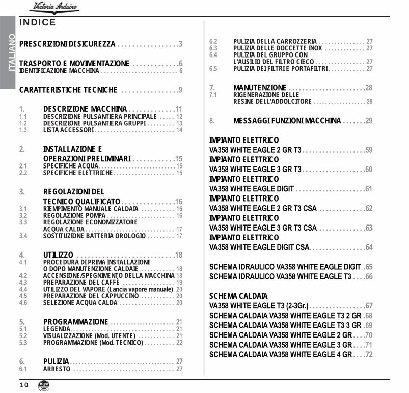
1.3 LISTA ACCESSORI
DESCRIZIONE 2 GRUPPI 3 GRUPPIFiltro singolo 1 1
Filtro doppio 2 3
Molla 2 3
Portafiltro 3 4
Becco erogazione doppio 2 3
Becco erogazione singolo 1 1
DESCRIZIONE 2 GRUPPI 3 GRUPPIPressa caffè 1 1
Filtro cieco 2 3
Tubo di scarico 3/4" 1 1
Tubo carico 3/8" 1 1
Panno in microfibra 1 1
Filtro singolo
Filtro doppio
Filtro cieco
Molla
Portafiltro
Becco erogazione doppio
Becco erogazione singolo
Panno in microfibra Tubo di scarico 3/4"
Tubo carico 3/8"
Pressa caffè

15
ITALIA
NOUna volta rimosso l’imballo e aver verificato
l’integrità della macchina e degli accessori, posizionare la macchina su un piano orizzonta-le e assicurarsi che sia correttamente livellata agendo sui piedini regolabili:
la macchina fino a un massimo di + 1 cm;-
re la macchina.
È responsabilità dell’utente la manutenzione del sistema di filtraggio e il monitoraggio delle specifiche acqua per mantenerle entro i livelli richiesti.Il non mantenere l’acqua entro le specifiche di seguito riportate comporta il completo decade-re della garanzia:
durezza totale 50-60 ppm (parti per milione).
fredda.
In fase preliminare, dopo la messa in piano della macchina, si consiglia di installare un addolcitore ( ), all’uscita della rete idrica, e di seguito un filtro a maglia (2).
Questo non permette alle impurità, come sab-bia, particelle di calcare in sospensione, ruggi-ne ecc.., di danneggiare le delicate superfici in grafite, garantendo una buona durata della macchina.
Dopo queste operazioni, provvedere ai collega-menti idraulici come illustrato nella seguente figura.
Fig. 5
2. INSTALLAZIONE E OPERAZIONI PRELIMINARI
2.1 SPECIFICHE ACQUA
Evitare strozzature nei tubi di collegamento.Verificare inoltre che lo scarico (3) sia in grado di eliminare gli scarti.
ATTENZIONE
NOTA: In caso di esercizi in cui il servizio è continuativo effettuare i ricambi di sopra descritti almeno con frequenza settimanale.
LEGENDA Addolcitore
2 Filtro a maglia3 Scarico Ø 50 mm
50 e 250 ppm.
ATTENZIONEPERICOLO DI SCOSSA ELETTRICA
La macchina deve essere sempre protetta con un interruttore automatico onnipolare di adeguata potenza con distanza di apertu-ra dei contatti uguale o superiore a 3 mm.Victoria Arduino non risponde di alcun danno a cose o persone derivante dalla mancata osservanza delle vigenti norme di sicurezza.
2.2 SPECIFICHE ELETTRICHE
Prima di allacciare la macchina a una rete elet-trica verificare che il voltaggio indicato sulla targhetta dati della macchina corrisponda a quello della rete.In caso contrario, effettuare i successivi colle-gamenti sulla base della linea elettrica a dispo-sizione, come illustrato successivamente:
/ 3 fasi + Neutro:
1 2 3 45
Fig. 7
Fig. 6
2
31

16
ITA
LIA
NO
Tutti i modelli VA358 sono muniti di sonda di livello, per mantenere costante il livello di acqua all’interno della caldaia.È buona norma, al primo avviamento della macchina, riempire manualmente la caldaia per evitare che la resistenza elettrica si dan-neggi e che inserisca la protezione elettronica.Se questo dovesse accadere, è sufficiente spegnere la macchina e riaccenderla, per com-pletarne il caricamento.
Per effettuare il primo riempimento manuale, agire come descritto di seguito:
A”, per permettere l’ingresso dell’acqua nella cal-daia;
”A” come illustrato nella seguente figura;
3.1 RIEMPIMENTO MANUALE CALDAIA
3. REGOLAZIONI DEL TECNICO QUALIFICATO
3.2 REGOLAZIONE POMPA
NOTA: Operazione eseguibile anche a mac-china accesa.
Per modificare la pressione di esercizio della caldaia, quindi la temperatura dell’acqua, in funzione delle varie esigenze o delle caratteri-stiche del caffè utilizzato, agire come descritto di seguito:
per AUMENTARE (senso orario) oppure DIMINUIRE (senso antiorario) la pressione;
Valore consigliato: 9 bar
visualizzata sul manometro, alloggiato all'in-terno della macchina;
LEGENDA Nero
2 Grigio3 Marrone
/ monofase
4 Blu 5 Giallo-verde
Operazione da eseguire a macchina spenta.
ATTENZIONE1 2 3 4
5
A

17
ITALIA
NO
3.4 SOSTITUZIONE BATTERIA OROLOGIO
La centralina elettronica è provvista di una batteria al litio per l’alimentazione dell’orologio con autonomia di circa tre anni, dopodiché può rendersi necessaria la sostituzione.
In caso di stop prolungato della macchina, l’o-rologio può essere bloccato:
con la macchina spenta, il display visualizza:
per 5 sec. per sbloccare l'orologio.
La sostituzione della batteria al litio deve essere eseguita SOLO dal Tecnico Specializzato. Victoria Arduino non risponde di alcun danno a cose o persone, derivanti da una mancata osservanza delle prescrizioni di sicurezza, descritte in questo manuale.
ATTENZIONE
OFF
OROLOGIO DISABILITATO
Al termine delle regolazioni, riposizionare la protezione in lamiera nell’apposito alloggiamen-to e fissarla con le due viti laterali; riposizionare il piatto raccogligocce e la griglia del piano di lavoro.
3.3 REGOLAZIONE ECONOMIZZATORE
ACQUA CALDANOTA: Operazione eseguibile anche a mac-
china accesa.
Tutti i modelli VA358 sono equipaggiati di un miscelatore di acqua calda, il quale permette di regolare la temperatura di uscita dell’acqua e di ottimizzare il rendimento del sistema.Per regolare l’economizzatore acqua calda, agire sul pomello di registro.
-giato all'interno della macchina;
ANTIORARIO / ORARIO per AUMENTARE / DIMINUIRE la temperatura dell’acqua calda;
-nello protettivo con le apposite viti.

18
ITA
LIA
NO L’operatore deve prima di iniziare la lavorazio-
ne, accertarsi di aver letto e ben compreso le prescrizioni di sicurezza di questo manuale.
In fase di prima installazione della macchina o dopo la manutenzione di una delle caldaie, accesa la macchina dall’interruttore generale posto in basso a destra, procedere come segue:
come al passo 3.-
mere il tasto ON/OFF fino a quando
-cedere come al passo 3.
3) Accendere la macchina premendo il tasto ON/OFF ed automaticamente dopo l’accensione uscirà acqua dai gruppi per circa 45 secondi al fine di assicurare il cor-retto riempimento delle caldaie caffè.
Questo ciclo non può e non deve essere interrotto.
Nel caso in cui sia interrotto per mancanza di elettricità o spegnimento accidentale della macchina dall’interruttore generale alla successiva riaccensione la macchina riavvierà di nuovo il ciclo per altri circa 45 secondi.
4.2 ACCENSIONE/SPEGNIMENTO DELLA MACCHINA
ACCENSIONE: collegare la macchina alla presa elettrica e premere l’in-
A I”, la macchina si accende.
In caso di manutenzione alla scheda elettro-nica, spegnere la macchina tramite l’inter-ruttore generale esterno o scollegare il cavo di alimentazione.
ATTENZIONE
ACCENSIONE / SPEGNIMENTO MANUALE
On - Off Automatico NON PROGRAMMATO
NOTA: assicurarsi che l’interruttore generale I”.
4. UTILIZZO
ACCENSIONE: premere il pulsante accensio-ne/spegnimento per circa 2 secondi fino all'illuminazione della spia ,
La centralina effettua l’autodia-gnosi delle funzioni, tutti i tasti di selezione si illuminano.
Terminata la diagnosi, sul display compare la "Home Page":
4.1 PROCEDURA DI PRIMA INSTALLA-ZIONE O DOPO MANUTENZIONE CALDAIE
A
Nel caso in cui l’autodiagnosi indichi ano-malie o guasti, l’operatore NON DEVE inter-venire; contattare il Centro di Assistenza.
ATTENZIONE
NOTA: La macchina non è operativa, in quanto l’interruttore generale permette solo l’a-limentazione della scheda elettronica.
OFF
NOTA: tutti i tasti di selezione sono abilitati sin dalla fine della diagnosi.
0.05 bar
21 MarzoDomenica 14:45

19
ITALIA
NO
On - Off Automatico PROGRAMMATO
NOTA: assicurarsi che l’interruttore generale I”.
La macchina si ACCENDERÀ al primo orario di accensione programmato (vedi capitolo PROGRAMMAZIONE e paragrafo RISPARMIO ENERGIA).
Nel caso in cui l’autodiagnosi indichi ano-malie o guasti, l’operatore NON DEVE inter-venire; contattare il Centro di Assistenza.
ATTENZIONE
Nel caso in cui l’autodiagnosi indichi ano-malie o guasti, chiamare il centro di assi-stenza, l’operatore NON DEVE intervenire.
ATTENZIONE
SPEGNIMENTO:premere il pulsante accensio-ne/spegnimento per circa 2 secondi fino allo spegnimen-to della spia .
La macchina si spegne e sul display è indicato:
OFF
0.05 bar
21 MarzoDomenica 14:45
NOTA: tutti i tasti di selezione sono abilitati sin dalla fine della diagnosi.
La macchina si SPEGNERÀ al primo orario di spegnimento programmato (vedi capitolo PROGRAMMAZIONE e paragrafo RISPARMIO ENERGIA).
NOTA: La macchina può essere accesa o spenta manualmente come indicato nel paragrafo precedente.
4.3 PREPARAZIONE DEL CAFFÈ
1) Dopo aver messo a punto la macchina, inserire il filtro desiderato (singolo o doppio all'interno del portafiltro).
2) Riempire a raso il dosatore di caffè e mette-re il caffè dentro il filtro.
3) Pressare il caffè nel filtro in maniera unifor-me con l'apposito pressino.
Nel caso la sequenza qui sotto descritta non si verifichi, consultare il capitolo "ANOMALIE E RIMEDI".
ATTENZIONE
La centralina effettua l’autodiagnosi delle fun-zioni, tutti i tasti di selezione si illuminano.Terminata la diagnosi, sul display compare la "Home Page":

20
ITA
LIA
NO
4.5 PREPARAZIONE DEL CAPPUCCINO
Per ottenere la tipica schiuma immergere il beccuccio del vapore in fondo al recipiente pieno per 1/3 (preferibilmente a forma tronco-conica). Aprire il vapore. Prima che il latte abbia
ATTENZIONEPERICOLO DI USTIONE
Per utilizzare il vapore è sufficiente tirare o spingere l’apposita leva come indicato in figura.Tirando completamente, la leva rimane blocca-ta nella posizione di massima erogazione, spingendo, il ritorno della leva è automatico.Le due lance vapore sono snodate, consenten-do un più agevole utilizzo delle stesse.
4.4 UTILIZZO DEL VAPORE (Lancia vapore manuale)
Durante l’uso della lancia del vapore, pre-stare molta attenzione a non mettere le mani sotto di essa e non toccarla subito dopo.
NOTA: L'utilizzo della lancia vapore deve esse-re sempre preceduta dall'operazione di spurgo della condensa per almeno 2 secondi o seguendo le istruzioni del costruttore.
4.6 SELEZIONE ACQUA CALDA
ATTENZIONEPERICOLO DI USTIONE
Durante l’uso della lancia dell’acqua calda, prestare molta attenzione a non mettere le mani sotto di essa e non toccarla subito dopo.Consente l’erogazione di acqua calda per pre-parare tè, camomilla e tisane.Posizionare sotto la lancia acqua calda un contenitore.Premere una volta sul pulsante selezione
acqua calda, la spia si illumina.Dalla lancia acqua calda verrà eroga-ta acqua per un tempo equivalente al valore programmato (vedi capitolo PROGRAMMAZIONE e paragrafo PROGRAMMAZIONE DOSI) o ripremere il pulsante per interrompere l'erogazione.
NOTA: L’erogazione dell’acqua calda può avvenire contemporaneamente a quel-la del caffè.
4) Pulire il bordo del filtro dai residui di caffè e inserire il porta filtro nel gruppo di erogazione.
5) Posizionare la/le tazzina/e sotto i beccucci.
6) In base al tipo di erogazione singola o dop-pia, premere il relativo pulsante di erogazio-ne .
7) Si attiva la pompa e inizia l'erogazione.8) Al raggiungimento della quantità impostata,
la pompa si spegne e l'erogazione termina automaticamente.
NOTA: Al termine di ogni erogazione di caffè, per la pulizia del gruppo, erogare acqua per 4-5 secondi.
0201
raggiunto lo stato di ebollizione, spostare il beccuccio del vapore in superficie facendo sfio-rare il latte con piccoli spostamenti in senso verticale. Alla fine dell’operazione pulire accura-tamente la lancia con un panno morbido.
21
ITALIA
NO
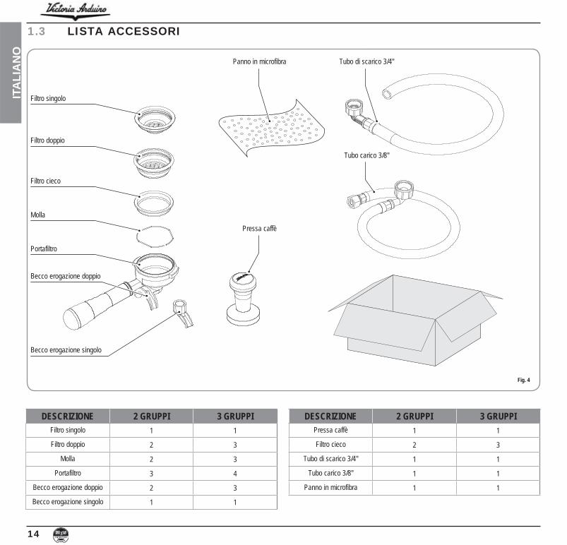
5. PROGRAMMAZIONE
5.1 LEGENDA
Fig. 21
① Display LCD.② Tasto RESET: per confermare e ritornare
allo step precedente.③ Tasto CURSORI: scorrimento dei menù ed ④ incremento e decremento valori.⑤ Tasto ENTER: per accedere all'interno del
menù.
LISTA FUNZIONI VISUALIZZABILI (Mod. UTENTE)
CICL. AUT. PULIZIADOSICONT. EROGAZIONITOTALITOTALE MACCHINACONT. LAVAGGI
5.2 VISUALIZZAZIONE (Mod. UTENTE)
Per entrare nell’ambiente di visualizzazione in modalità utente premere il tasto ENTER per alcuni secondi.La macchina visualizzerà:
0.05 bar
21 MarzoDomenica 14:45
CICL. AUT. PULIZIADOSI
CONT. EROGAZIONITOTALI
TOTALE MACCHINACONT. LAVAGGI
CICLO AUTOMATICO DI PULIZIA
CICL. AUT. PULIZIA
ENTER e sul display verrà visualiz-zato:
CICL. AUT. PULIZIA
SELEZIONA
di ogni gruppo comincerà a lam-peggiare. Inserire il filtro cieco nel portafiltro, aggiungere mezza dose di detergente e agganciare il portafiltro al gruppo sul quale si vuole procedere con il lavaggio automatico. È possibile effettuare il lavaggio anche in più gruppi contemporaneamente.
per avviare il ciclo di pulizia automatico sul gruppo. Sul display comparirà:
CICL. AUT. PULIZIA
¡ W
attivato il ciclo di lavaggio. Terminato il ciclo di 15 erogazioni da 5 secondi l’una, con una pausa fra le erogazioni di 10 secondi, il tasto
del gruppo selezionato torna a lampeg-giare e sul display comparirà:
CICL. AUT. PULIZIA
¡ R
-
to il ciclo di risciacquo. Premere il tasto per avviare il risciacquo.
RESET per visualizzare la funzione successiva o per uscire dalla visua-lizzazione.
DOSI
DOSI
ENTER per accedere alle regolazioni di:
I relativi pulsanti lampeggiano.
display verrà visualizzato il corrispondente valore programmato.
RESET per uscire dalla visualizzazione.
4
3
12
5

22
ITA
LIA
NO
CONTEGGIO EROGAZIONI
CONT. EROGAZIONI
ENTER e tutti i tasti dose, acqua calda e vapore lampeggeranno.
display verrà visualizzato il corrispondente contatore.
per azzerare il contatore del gruppo.RESET per uscire dalla
visualizzazione.
TOTALE
TOTALI
di ciascun gruppo lampeggerà e premendolo potrà essere visualizzato il nume-
funzioni.
TOTALE GRUPPO
XXX
RESET per uscire dalla visualizzazione.
TOTALE MACCHINA
TOTALE MACCHINA
EROGAZ. xxx
funzioni.RESET per uscire dalla
visualizzazione.
CONTEGGIO LAVAGGI
CONT. LAVAGGI
di ciascun gruppo lampeggerà e premendolo potrà essere visualizzato il numero di cicli di lavaggio eseguiti per quel dato gruppo.
funzioni.RESET per uscire dalla
visualizzazione.
LISTA FUNZIONI PROGRAMMABILI (MOD. TECNICO)
PROGRAM. DOSI CICL. AUT. PULIZIA CONT. EROGAZIONI PROGRAM. ON/OFF PROGRAM. SCALDATAZZE DATA/ORA TEMPO EROGAZ. SETPOINT PRESS. °STORICO ALLARMI MANUTENZIONE SETPOINT TEMP. *LINGUA INFORMAZIONI
Operazione eseguibile SOLO da Tecnico Specializzato. La regolazione da parte di
Tecnici NON qualificati o di altre persone potreb-be invalidare la garanzia.
* Solo versione T3° Solo versione Digit
5.3 PROGRAMMAZIONE (Mod. TECNICO)
Per entrare nell’ambiente di visualizzazione in modalità tecnico premere e tenere premuto a lungo il tasto ENTER e attendere il secondo segnale acustico. Il display visualizzerà:
0.05 bar
21 MarzoDomenica 14:45
PROGRAMMAZIONE DOSICICL. AUT. PULIZIACONT. EROGAZIONIPROGRAM. ON-OFF
PROGRAM. SCALDATAZZEDATA/ORA
PROGRAMMAZIONE DOSI
PROGRAM. DOSI
ENTER, il display visualiz-zerà:
PROGRAM. DOSI
SELEZIONA
Tutti i tasti programmabili cominceranno a lampeggiare.
display visualizza:
VOLUME C.C:
Seguita dal valore già programmato dalla casa costruttrice.

23
ITALIA
NO
inizierà l’erogazione (nel frattempo tutti gli altri tasti si spegneranno).
-
per arresta-re l'erogazione.
che sarà ancora possibile modificare con i
ENTER per confermare la dose programmata.
RESET per annullare la programmazione.
Acqua calda e assicurarsi che lo
stesso si illumini. Sul display comparirà la scritta:
PROGRAM. DOSI
SEC. ACQ. X.X
fuoriuscita dell’acqua calda da versare.
premere nuovamente il pulsante .
Inizia l’erogazione. Quando la dose deside-
.
da noi impostato ancora modificabile sele-
ENTER o passare ad una successiva selezione per concludere l’ope-razione.
RESET per annullare la programmazione.
Il pulsante si spegne.
Vapore temporizzato/temperatura e assicurarsi che lo
stesso si illumini. Nelle versioni con sonda di temperatura
(optional) la centralina riconosce automati-camente la presenza della sonda e sul display comparirà la scritta:
PROGRAM. DOSI
TEMP. VAP. C
seguita dal valore già impostato dalla casa costruttrice.
-tura che deve raggiungere la bevanda da riscaldare. Raggiunta tale temperatura si fermerà automaticamente l’erogazione del vapore.
temperatura) premendo il tasto sul display comparirà la scritta:
PROGRAM. DOSI
SEC. VAP.
seguita dal valore già impostato dalla casa
variare il tempo di fuoriuscita del vapore da erogare.
premere nuovamente il pulsante .
Inizia l’erogazione. Quando la dose desiderata .
da noi impostato ancora modificabile sele-
ENTER o passare a una successiva selezione per concludere l’ope-razione.
RESET per annullare la programmazione.
Il pulsante si spegne.
CICLO AUTOMATICO DI PULIZIA
CICL. AUT. PULIZIA
ENTER e sul display verrà visualiz-zato:
CICL AUT. PULIZIA
SELEZIONA
di ogni gruppo comincerà a lampeggiare. Inserire il filtro cieco nel porta-filtro, aggiungere mezza dose di detergente e agganciare il portafiltro al gruppo sul quale si vuole procedere con il lavaggio automati-co. È possibile effettuare il lavaggio anche in più gruppi contemporaneamente.
per avviare il ciclo di pulizia automatico sul gruppo. Sul display comparirà:
CICL. AUT. PULIZIA
¡ W
attivato il ciclo di lavaggio. Terminato il ciclo di 15 erogazioni da 5 secondi l’una, con una pausa fra le erogazioni di 10 secondi, il tasto
del gruppo selezionato torna a lampeg-giare e sul display comparirà:
CICL. AUT. PULIZIA
¡ R
-
to il ciclo di risciacquo. Premere il tasto per avviare il risciacquo.

24
ITA
LIA
NO
RESET per visualizzare la funzione successiva o per uscire dalla visua-lizzazione.
CONTEGGIO EROGAZIONE
CONT. EROGAZIONI
ENTER sul display appa-rirà:
TOTALE SELEZIONE
SELEZIONA
-giare. Premendo uno dei tasti erogazione si visualizza il numero delle relative erogazioni effettuate.
RESET per 3 secondi.
NOTA:un’erogazione.
TOTALE MACCHINA
EROGAZ. XXXX
Questo valore indica il numero totale di ero-gazioni effettuate.
RESET per 3 secondi.
CONTAT. LAVAGGI
per accedere al conteggio dei lavaggi auto-matici premere ENTER.
, premendo il tasto del gruppo si visualizza il numero di cicli di lavaggio effettuati. Mantenendo premuto il tasto RESET per 3 secondi si azzera il contatore.
PROGRAM. ON/OFF
PROGRAM. ON-OFF
ENTER, il display visualiz-zerà:
LUNEDI’
ON 07:30 OFF 23.30
i valori di ON e OFF indicano l’ora di accen-sione e spegnimento.
-sivi o precedenti.
ENTER per variare l’orario pro-grammato per l’accensione (la scritta ON 07:30 comincerà a lampeggiare).
accensione.ENTER per confermare e per pas-
sare all’orario programmato per lo spegni-
lampeggiare).
spegnimento.ENTER.
-to nel giorno di riposo settimanale, premere RESET.
Sul display verrà visualizzato:
RIPOSO SETTIMAN.
(per ripristinare, premere RESET)
bip indica il passaggio alla pagina successiva.
PROGRAMMAZIONE SCALDATAZZE
PRO. SCALDATAZZE
Programmazione a tempoENTER, il display visualiz-
zerà per esempio:
PRO. SCALDATAZZE
ON XX OFF xx
La scritta ON XX comincerà a lampeggiare, -
tazze aperto (compreso tra 0 e 60 min).ENTER per confermare e per pas-
sare al tempo di scaldatazze OFF, compreso tra 0 e 60 min.
NOTA: Programmando uno dei due valori ON/OFF a 0 la funzione viene automatica-mente esclusa.
per alcuni secondi per passare alla pagina successiva.

25
ITALIA
NO
DATA/ORA
DATA/ORA
ENTER, il display visualiz-zerà per esempio:
LUNEDI 08:22
01 FEBBRAIO 2016
Le ore cominceranno a lampeggiare.
ENTER.
Una volta variati le ore e i minuti premere nuovamente ENTER e variare il giorno, il mese e l’anno utilizzando la procedura sopra descritta.
Al termine premere ENTER per passare alla pagina successiva.
TEMPO DI EROGAZIONE
erogazione dipendenti dalla macinatura del
TEMPO DI EROGAZ.
ENTER il display visualiz-zerà:
TEMPO DI EROGAZ.
XXX
XXX come:NON ATTIVO: non verranno visualizzati i tempi di erogazione. TEMPORIZZATO: verranno visualizzati i tempi di erogazione.PERSISTENTE: viene visualizzato il tempo dell'ultima erogazione.
ENTER per confermare e passare alla fase successiva.
RESET per tornare alla pagina precedente senza confermare.
SETPOINT PRESSPermette di scegliere la pressione/temperatura di lavoro a regime.
SETPOINT PRESS
Premendo il tasto ENTER il display visualizzerà:
SETPOINT PRESS
XX.XX BAR
Premere per regolare il punto di lavoro-press/temp.
ENTER per confermare e passare alla fase successiva.
RESET per tornare alla pagina precedente senza confermare.
TABELLA PRESSIONE - TEMPERATURA
Bar °C °F
STORICO ALLARMI
STORICO ALLARMI
ENTER, il display visualiz-zerà:

26
ITA
LIA
NO
ERRORE 01
dieci allarmi memorizzati. Dopo il decimo
passa alla pagina successiva.
MANUTENZIONE
MANUTENZIONE
ENTER, il display visualiz-zerà:
EROGAZIONI 10000
01 GENNAIO 2005
-bi i valori.
ENTER per confermare. Raggiunto il limite impostato di erogazioni o
raggiunta la data fissata per la manutenzio-ne sul display comparirà la scritta:
MANUTENZIONE
Per far scomparire la parola MANUTENZIONE occorrerà spostare la data in avanti oppure
SETPOINT TEMPERATURA(SOLO VERSIONE T3)
-do il tasto ENTER.
varie caldaie e dei vari gruppi, il tasto ENTER conferma e passa al valore succes-sivo. Confermando l’ultimo gruppo si torna al menù principale.
Premendo il tasto RESET si va alla regola-zione del valore successivo, le eventuali modifiche apportate non vengono memoriz-zate.
SETP G1: Temperatura gruppo 1 SETP C1: Temperatura caldaia 1
SETP G3: Temperatura gruppo 3 SETP C3: Temperatura caldaia 3
SETPOINT TEMPERATURA
SETPOINT TEMP
per alcuni secondi, si accede alla funzione OFFSET.
delle varie caldaie dei gruppi.ENTER conferma e passa al valore
successivo.
principale.RESET si va alla regola-
zione del valore successivo e le eventuali modifiche apportate non vengono memoriz-zate.
OFFS. G1 : Offset gruppo 1 OFFS. C1 : Offset caldaia 1
OFFS. G3 : Offset gruppo 3 OFFS. C3 : Offset caldaia 3
LINGUA
LINGUA
ENTER, sul display verrà visualizzata la lingua già impostata. Scegliere
ENTER per confermare e passare alla fase successiva.
RESET per tornare alla pagina precedente senza confermare.
INFORMAZIONIIl display visualizza le informazioni della scheda elettronica di potenza e del display:
REL. POWER 0.13
REL. TFT 0.11

27
ITALIA
NO
6. PULIZIA
6.1 ARRESTO
6.2 PULIZIA DELLA CARROZZERIA
6.3 PULIZIA DELLE DOCCETTE INOX
6.4 PULIZIA DEL GRUPPO CON L'AUSILIO DEL FILTRO CIECO
Per arrestare la macchina bisogna ripremere l’interruttore generale e portarlo nella posizione "O".
Prima di effettuare qualsiasi operazione di puli-zia, bisogna portare la macchina a stato ener-getico “Osezionatore aperto).
Pulizia zona lavoro: togliere la griglia del pia-nolavoro sollevandolo anteriormente verso l’alto e sfilarlo, togliere il sottostante piatto raccogliac-qua e pulire il tutto con acqua calda e detersivo.Pulizia carena: per pulire tutte le parti cromate utilizzare un panno morbido inumidito.
Le doccette inox sono situate sotto i gruppi erogazione.
gruppo erogazione tramite detergente specifico in polvere.La macchina inizierà il ciclo di pulizia che consi-ste nel ricircolo di acqua calda intervallata da un tempo di attesa.È consigliabile effettuare il lavaggio almeno una volta al giorno con gli appositi detergenti.
ATTENZIONE
ATTENZIONE
Non utilizzare solventi, prodotti a base di cloro, abrasivi.
Non è possibile pulire l'apparecchio con getto d'acqua o immergendolo in acqua.
Fig. 22
NOTA: Per la pulizia operare come descritto:
siano ostruiti.-
zione. Si raccomanda di effettuare la pulizia delle
doccette settimanalmente.
ATTENZIONE PERICOLO DI INTOSSICAZIONE
Una volta tolto il portafiltro effettuare alcune erogazioni per eliminare eventuali residui di detergente.
Per eseguire la procedura di lavaggio procede-re come segue:
erogatore.-
te specifico in polvere e immettere il portafil-tro al gruppo.
10 sec.
erogazioni.
6.5 PULIZIA DEI FILTRI E PORTAFILTRI
Mettere due cucchiaini di detergente specifico in mezzo litro d’acqua calda e immetervi filtro e portafiltro (escluso il manico) per almeno mezz’ora. Dopodiché risciacquare in abbondan-te acqua corrente.

28
ITA
LIA
NO
verso sinistra, lasciando scaricare l’acqua salata dal tubo F finché non ritorni dolce
Fig. 26
3) Riportare quindi la leva D verso sinistra.
Fig. 27
Fig. 24
Fig. 25
ENTRATA
USCITA7.1 RIGENERAZIONE
DELLE RESINE DELL’ADDOLCITORE
Al fine di evitare la formazione di depositi calca-re all’interno della caldaia e degli scambiatori di
-pre in perfetta efficienza. Occorre perciò effet-tuare regolarmente la rigenerazione delle resi-ne ioniche.I tempi di rigenerazione vanno stabiliti in funzio-
della durezza dell’acqua utilizzata.Indicativamente si possono rilevare dal dia-gramma riportato nella figura seguente.
Le procedure di rigenerazione sono le seguenti:1) Spegnere la macchina e mettere un reci-
piente della capacità di almeno 5 litri sotto il tubo E.
Ruotare le leve C e D da sinistra verso destra; togliere il tappo svitando la mano-pola G e introdurre 1 Kg di sale grosso da cucina.
Fig. 23
7. MANUTENZIONENOTA: Durante la manutenzione / riparazione i
componenti utilizzati devono garantire di mantenere i requisiti di igiene e sicu-rezza previsti per il dispositivo. I ricambi originali forniscono questa garanzia.
NOTA: Dopo una riparazione o una sostituzio-ne di componenti che riguardano parti a contatto con acqua e alimenti, deve essere effettuata la procedura di lavag-
procedure indicate dal costruttore.
C
C
FC
G
E
D
C
D

29
ITALIA
NO
8. MESSAGGI FUNZIONI MACCHINA
INDICAZIONI DISPLAYE TASTI CAUSA EFFETTO SOLUZIONE NOTA
ERRORE DIAGNOSI
Al momento della diagnosi il sistema presenta delle anomalie sulle eprom della
centralina.
La macchina non riscalda e tutte le funzioni sono bloc-
cate.
ERRORE EROGAZIONE
Raggiunto il tempo limite
dosatore non ha inviato gli impulsi programmati.
L'indicazione sul display lampeggia così come il ta-sto "continuo" del relativo
gruppo.
Premere il tasto RESET o uno dei tasti .
ERRORE DOSATORE
Se entro i primi tre secon-di dall'inizio erogazione, il dosatore non ha inviato gli
impulsi programmati.
-rotta manualmente si arriva al blocco di tempo limite
Premere il tasto RESET o uno dei tasti .
ERRORE LIVELLO
-namento della macchina il livello dell'acqua non viene
ripristinato.
L'indicazione sul display lampeggia.
La pompa si disattiva.La resistenza e tutte le fun-
zioni sono inibite
Spegnere la macchina e ri-accenderla.
Si riattiveranno le funzioni.
ERRORE PRESSIONE Quando la temperatura del-la macchina supera i 130°C.
L'indicazione sul display lampeggia, e la resistenza
si disattiva.
Il sistema si autoripristina non appena la temperatura
scende sotto i 130°C.
termostato di sicurezza a riarmo manuale, se la resi-stenza non si ripristina chia-
mare untecnico specializzato.
ERR. SOVRACORR.Errato assorbimento dovuto al mal funzionamento di un
carico della macchina
L'indicazione sul display lampeggia. La pompa si di-sattiva. La resistenza e tutte
le funzioni sono inibite.
Spegnere la macchina echiamare un tecnico
specializzato.
MACINATURA FINE La macchina rileva valori di-versi da quelli impostati.
Tempo molto più lungo dierogazione.
Cambiare grado di macina-tura e premere il tasto RE-SET o uno dei tasti .
Lasciando la macchina nel-lo stato di programmazione, dopo 10 min. dall'ultima selezione, il sistema ritorna
-dente e il display indica il
normale funzionamento.
MACINATURA GROSSA La macchina rileva valori di-versi da quelli impostati.
Tempo molto più corto dierogazione.
Premere il tasto RESET o uno dei tasti .

30
ITA
LIA
NO
NOTE______________________________________________________________________________
______________________________________________________________________________
______________________________________________________________________________
______________________________________________________________________________
______________________________________________________________________________
______________________________________________________________________________
______________________________________________________________________________
______________________________________________________________________________
______________________________________________________________________________
______________________________________________________________________________
______________________________________________________________________________
______________________________________________________________________________
______________________________________________________________________________
______________________________________________________________________________
______________________________________________________________________________

31
ENG
LISHSAFETY INDICATIONS The present manual is an integral and essential part of the product and is to be delivered to the user. Carefully read all warnings in the manual as they pro-vide important information required to install, use and maintain the unit safely. Keep this manual in a safe place for further consultation.
After having removed the packaging, make certain that the unit is not dam-aged in any way.If you have any doubts, do not use the unit and contact a professionally quali-fied person. Always keep all packaging (plastic bags, polystyrene foam, nails, etc.) out of the reach of children as they are a potential source of danger and never loiter the environment with such materials.
DANGER OF POLLUTION
The machine is can be installed in staff kitchen areas in shops, offices and other working environments, farm houses by clients in hotels, motels and other residential type environments bed and breakfast type environments.
Before turning on the unit make certain that the rating indicated on the label matches the available power supply. The nameplate can be seen inside the
machine when removing the water col-lection tray. The machine must be installed according to the applicable federal, state and local standards (codes) in force with regard to plumbing systems including back-flow prevention devices. For this reason, the plumbing connections must be carried out by a qualified technician.The warranty expires if the characteris-tics of the power supply do not corre-spond to the nameplate data.
The manufacturer cannot be held responsible for any damages incurred if the system is not grounded.For electrical safety, this machine requires a ground system. Contact a technically certified electrician who must check that the line electrical capac-ity is adequate for the maximum capaci-ty indicated on the unit label.
The qualified electrician must also check that the section of the installation’s cables is large enough for the absorbed power of the appliance.Never use adapters, multiple jacks or extension cords. When such items prove absolutely necessary, call in a qualified electrician.
When installing the device, it is neces-sary to use the parts and materials sup-plied with the device itself. Should it be necessary to use other parts, the instal-lation engineer needs to check their suitability for use in contact with water for human consumption.The installer must Make the hydraulic connections respecting the rules of hygiene and water safety to environ-mental protection in force in the place of installation. So for the hydraulic plant contact an authorized technician. Always utilise the new hose supplied for connection to the water supply. Old hoses must not be utilised.
The device needs to be supplied with water that is suitable for human con-sumption and compliant with the regula-tions in force in the place of installation. The installation engineer needs confir-mation from the owner/manager of the system that the water complies with the requirements and standards stated above.
This unit must only be used for the pur-poses described in the present manual. The manufacturer cannot be held respon-sible for any damages caused by improp-er, mistaken and unreasonable use.
The appliance is not to be used by chil-dren or persons with reduced physical, sensory or mental capabilities, or lack of experience and knowledge, unless they have been given supervision or instruc-tion. Children must not play with the appliance. Cleaning and maintenance
32
ENG
LISH
must not be carried out by children unless supervised.
This appliance is for professional use only.
The operating temperature must be within the range of [+5, +35]°C.At the end of installation, the device is switched on and taken to rated operat-ing conditions, leaving it in a state in which it is “ready for operation”.
After reaching the “ready for operation” condition, the following dispensing operations are carried out:
the coffee dispenser (for more than one dispenser, this is divided equally);
At the end of installation, it is good prac-tice to draw up a report of the operations.
WARNING
Before using the machine, read this manual in its entirety or, at the very least, read the safety and set up instruc-tions.
There are some basic rules for the use of any electrical appliance.In particular:
hands or feet;
areas equipped with baths or showers;
cord to unplug the unit;
atmospheric agents (rain, direct sunlight, etc..);
personnel or anyone who has not read this manual operate the unit.
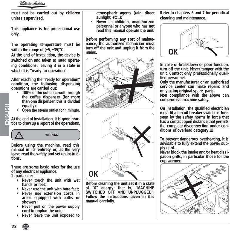
Before performing any sort of mainte-nance, the authorized technician must turn off the unit and unplug it from the mains.
OKBefore cleaning the unit set it in a state
Follow the instructions given in this manual carefully.
Refer to chapters 6 and 7 for periodical cleaning and maintenance.
OKIn case of breakdown or poor function, turn off the unit. Never tamper with the unit. Contact only professionally quali-fied personnel.Only the manufacturer or an authorized service center can make repairs and only using original spare parts.Non compliance with the above can compromise machine safety.
On installation, the qualified electrician must fit a circuit breaker switch as fore-seen by the safety norms in force that has a contact open distance that permits the complete disconnection under con-ditions of overload category III.
To prevent dangerous overheating, it is advisable to fully extend the power sup-ply cord.Never block the intake and/or heat dissi-pation grills, in particular those for the cup warmer.

33
ENG
LISH
CAUTION
USERSUnder the senses of art.
“Implementation of the Directives/ Guidelines
-tion of the use of dangerous substances in electric and electronic equipment, as well as the disposal of wastes“.
The symbol of the crossed large rubbish container that is present on the machine points out that the product at the end of its life cycle must be collected separately from the other wastes. The user for this reason will have to give the equipment that got to its life cycle to the suitable separate waste collection centres of electronic and elec-tro-technical wastes, or to give it back to the seller or dealer when buying a new equipment of equivalent type, in terms of one to one.
DANGER OF BURNS
To facilitate aeration of the unit, position
from walls or other machinery.
Be extremely careful when using the steam nozzle. Never place your hands under the nozzle and never touch it right after use.
Remember that to install, maintain, unload and regulate the unit, the quali-fied operator must always wear work gloves and safety shoes.
When adding the coffee, the operator must never put his hands into the con-tainer.The noise level of the machine is less
For machines connected to the mains water supply, the minimum pressure
-sure for correct machine operation must not exceed 4 bar.
The user must never replace the unit's power supply cord. If this cord is dam-aged, turn off the unit and have it replaced by a professionally qualified technician.
Should it be necessary to replace the power cord, this replacement operation must only be performed by an authorized service centre or by the manufacturer.
Should you decide to stop using this type of unit, we suggest you render it inopera-ble by unplugging it and cutting the power supply cord.
DANGER OF POLLUTION
Never dispose of the machine in the envi-ronment: to dispose of the machine, contact an authorized center or contact the manufacturer for pertinent indica-tions.
DANGER OF INTOXICATION
Once started the washing machine, do not interrupt, the detergent residue may remain inside the delivery unit.

34
ENG
LISH
CAUTION
Before performing the following opera-tions, make certain that the load is in stable and will not fall when the straps are cut.Wearing gloves and safety shoes, the operator must cut the straps and store the product. During this operation, see the product technical features for the weight of the machine being stored and proceed as necessary.
DANGER OF POLLUTION
Once the machine has been released from the pallet or container, do not pol-lute the environment with these items.
MACHINE ID
When communicating with the manufacturer Nuova Simonelli, always cite the machine ID number.
The machine is transported on pallets contain-ing several machines inside cartons strapped to the pallet.Operators performing any shipping or handling operations must:
Wear gloves, safety shoes and overalls with elasticized cuffs.
Always move pallets using adequate equipment (i.e. fork lift trucks).
CAUTION
During handling, the operator must make certain that there are no persons, things or objects in the vicinity.
cm off the ground and drive to the load-ing zone. After having made certain that there are no obstacles, things or per-sons in the way, proceed with loading.Once the destination has been reached, again using adequate lifting equipment (i.e. fork lift truck) and after having made certain that there is nothing and no one in the unloading area, set the pallet on the ground and move it to the storage area; always carry the load at a height of
SHIPPING AND HANDLING

35
ENG
LISHCongratulations,
By purchasing the VA358 WHITE EAGLE you have made an excellent choice.The purchase of a professional espresso coffee-maker involves various elements of selection: the name of the manufacturing firm, the machine’s specific functions, its technical reliability, the option of immediate and suitable servicing, its price. You certainly evaluated all these factors and then
made your choice: the VA358 WHITE EAGLE .We think you have made the best choice and after every coffee and cappuccino you will be able to assess this.
You will see how practical, convenient and efficient working with VA358 WHITE EAGLE .If this is the first time you have bought a Victoria Arduino coffee machine, welcome to high quality coffee-making; if you are already a customer of ours, we feel flattered by the trust you have shown us.
Thanks of the preference.With best wishes,Victoria Arduino


37
ENG
LISHTECHNICAL CHARACTERISTICS
1050 (41,34)870 (34,25)
511
(20,
12)
659 (25,94)
125 (4,92)
371 (14,61)
169
(6,6
5)
2 Groups 3 GroupsNET WEIGHT 71 kg 156 lb 91 kg 200 lb
GROS WEIGHT 87 kg 191 lb 111 kg 244 lb
POWER 4500 W 5200 W
CAPACITY STEAM BOILER 11,4 l 385,48 oz 17,3 l 584,98 oz
VOLTAGE 380 V three-phase 50 Hz
2 Groups 3 GroupsNET WEIGHT 74 kg 163 lb 95 kg 209 lb
GROS WEIGHT 90 kg 198 lb 115 kg 253 lb
POWER 7600 W 9500 W
CAPACITY BOILER GROUP 0,7 l 23,67 oz 0,7 l 23,67 oz
CAPACITY STEAM BOILER 11,4 l 385,48 oz 17,3 l 584,98 oz
VOLTAGE 208 - 240 V three-phase 50 - 60 Hz
T3
Digit
NOTE: The image shows the dimensions for the 3-groups. The version 2 groups is reduced to 230 mm in length.

38
ENG
LISH
INDEX
SAFETY INDICATIONS . . . . . . . . . . . . . . . . . . . . . . .
. . . . . . . . . . . . . . . . . . .34 . . . . . . . . . . . . . . . . . . . . . . . . . . . . . . . . . . . . . . . 34
. . . . . . . . . . . . . .37
DESCRIPTION . . . . . . . . . . . . . .MAIN KEYBOARD DESCRIPTION . . . . . . . . . . . . . .GROUPS KEYBOARD DESCRIPTION . . . . . . . . . . .ACCESSORIES LIST. . . . . . . . . . . . . . . . . . . . . . . . .
INSTALLATION AND PRELIMINARY OPERATIONS . . . . . . . . . . .43
WATER SPECIFICATIONS . . . . . . . . . . . . . . . . . . . . 43ELECTRICAL SPECIFICATIONS . . . . . . . . . . . . . . . 43
3. ADJUSTMENTS TO BE MADE BY A QUALIFIED ONLY. . . . .44
FILLING BOILER MANUALLY . . . . . . . . . . . . . . . . . 44PUMP ADJUSTMENT . . . . . . . . . . . . . . . . . . . . . . . . 44
3.3 WATER ECONOMISER ADJUSTMENT . . . . . . 453.4 CLOCK BATTERY. . . . . . . . . . . . 45
4. USE . . . . . . . . . . . . . . . . . . . . . . . . . . . . . . . . . . .46COMMISSIONING PROCEDURE
OR AFTER BOILER MAINTENANCE . . . . . . . . . . . . 46 ON/OFF. . . . . . . . . . . . 46
4.3 MAKING COFFEE . . . . . . . . . . . . . . . . . . . . . . . . . . . 474.4 USING STEAM (Manual steam wand) . . . . . . . . . . .4.5 MAKING CAPPUCCINO . . . . . . . . . . . . . . . . . . . . . .4.6 WATER SELECTION. . . . . . . . . . . . . . . . . . . . .
5. PROGRAMMING . . . . . . . . . . . . . . . . . . . . .KEY. . . . . . . . . . . . . . . . . . . . . . . . . . . . . . . . . . . . . . .VISUALIZATION (USER Mode). . . . . . . . . . . . . . . . .
5.3 PROGRAMMING . . . . . . . . . .
6. CLEANING . . . . . . . . . . . . . . . . . . . . . . . . . .55 OFF . . . . . . . . . . . . . . . . . . . . . . . . . . . . 55
. . . . 55
6.3 . 556.4 . . . . . . . . . . . . . . . 556.5 . . . . 55
7. MAINTENANCE . . . . . . . . . . . . . . . . . . . . . .56RESIN AND SOFTENER REGENERATION . . . . . . . . 56
FUNCTION MESSAGES. . . . . . .57
ELECTRIC SYSTEM. . . . . . . . . . . . . . . . . . .
ELECTRIC SYSTEM. . . . . . . . . . . . . . . . . . .
ELECTRIC SYSTEM . . . . . . . . . . . . . . . . . . . . .
ELECTRIC SYSTEM . . . . . . . . . . . . . .
ELECTRIC SYSTEM . . . . . . . . . . . . . .63
ELECTRIC SYSTEM. . . . . . . . . . . . . . . . .64
. . . . . . . . . . . . . . . . . . . . .65 . .66
BOILER DIAGRAM. . . . . . . . . . . . . . . . .67
. .
. . . . . . . . . . . .

39
ENG
LISH1. DESCRIPTION MACHINE
Steam delivery lever
Hot water nozzle
Pressure Gauge
Support foot
Steam nozzle
Support foot
Drip tray
Filter-Holder
Support foot
Steam nozzle
Steam delivery lever
Electric Cup-Warmer
Delivery unit
Cup Rack
Buttons coffee dispenser

40
ENG
LISH
1.1 MAIN KEYBOARD DESCRIPTION
Autosteam button
Water dispensing button RESET button
Scroll or increase / decrease buttons
ENTER button TFT Display
Stand-by button Cup-Warmer button Washing button

41
ENG
LISH1.2 GROUPS KEYBOARD DESCRIPTION
Fig. 3
1 espresso key 2 espresso key
Continuous delivery key
1 long coffee key 2 long coffee key

42
ENG
LISH
Fig. 4
1.3 ACCESSORIES LIST
DESCRIPTION 3 GROUPSSingle filter 1 1
Double filter 2 3
Spring 2 3
Filter-holder 3 4
Double delivery spout 2 3
Single delivery spout 1 1
DESCRIPTION 3 GROUPSCoffee presser 1 1
Blind filter 2 3
Draining tube 3/4" 1 1
Filling tube 3/8" 1 1
Microfibre cloth 1 1
Single filter
Double filter
Blind filter
Spring
Filter-holder
Double delivery spout
Single delivery spout
Microfibre cloth Draining tube 3/4"
Filling tube 3/8"
Coffee presser

43
ENG
LISH
Once the machine is out of the packaging and its integrity, and that of the accessories has been checked, place it on a flat, horizontal surface and if necessary, use the adjustable feet to make sure it is correctly level:
up to a maximum of + 1 cm;
machine.
Monitoring of water recipe to keep it within required levels and maintenance of filtration system is the user's responsibility.Failing to meet and maintain water at the fol-lowing levels will void the entire warranty:
water to be cold.
It is advisable to install a softener ( ) and then a mesh filter ( ) on the external part of the plumbing system, during preliminaries and after levelling the machine.
In this way impurities like sand, particles of calcium, rust etc.. will not damage the delicate graphite surfaces and durability will be guaran-teed.
Following these operations, connect the plumb-ing systems as illustrated in the following figure.
Fig. 5
2. INSTALLATION AND PRELIMINARY OPERATIONS
2.1 WATER SPECIFICATIONS
Avoid throttling in the connecting tubes.Assess that the drain pipe (3) is able to eliminate waste.
WARNING
NOTE: In case of exercises in which the ser-vice is continuing make parts of the above at least weekly.
Fig. 6
KEY Softener Mesh filter
3 Drain Ø 50 mm
CAUTION
The machine must always be protected by an automatic omnipolar switch of suitable power with contact openings of equal dis-tance or more than 3mm.Victoria Arduino is not liable for any damage to people or objects due to not observing current security measures.
2.2 ELECTRICAL SPECIFICATIONS
Prior to connecting the machine to the electrical mains, assess that the voltage shown on the machine’s data plate corresponds with that of the mains.If it does not, carry out the connections on the basis of the available electrical line, as follows:
/ 3 phases voltage + Neutral:
1 2 3 45
Fig. 7
2
31

44
ENG
LISH
All models VA358 are equipped with a level gauge to keep the water level inside the boiler constant.When using the machine for the first time, it is advisable to fill the boiler by hand to avoid damaging the electrical resistor and turning on the electronic protection.If this should happen, just turn the machine off and then start it up again to complete its load-ing procedure.
To fill the boiler manually for the first time, pro-ceed as follows:
A” level tap so that water will enter the boiler;
”A” as illustrated in the following figure;
3.1 FILLING BOILER MANUALLY
3. ADJUSTMENTS TO BE MADE BY A QUALIFIED TECHNICIAN ONLY
3.2 PUMP ADJUSTMENT
NOTE: This operation can be carried out while the machine is turned on.
To adjust the service pressure of the boiler, thus regulating the water temperature, accord-ing to the various functions and needs of the coffee desired, proceed as follows:
Remove the grid and the drip tray;
clockwise to INCREASE and counter clock wise to DECREASE the pressure;
Advisable pressure: 9 bar
The set pump pressure is displayed in the pressure gauge, inside the machine;
1 2 3 45
KEY Black Gray
3 Brown
/ monophase voltage:
4 Blue5 Yellow - green
This operation must be carried out with the machine is turned off.
WARNING
A

45
ENG
LISH3.4 REPLACING THE
CLOCK BATTERY
The electronic control unit has a lithium battery to power the clock; the battery has an autono-my of about three years, after which it will need to be replaced.
In case of an extended period of machine stop-page, the clock can be stopped:
for 5 sec. to release the clock.
Replacement of the lithium battery must be carried out EXCLUSIVELY by Qualified Technician.Victoria Arduino cannot be held liable for any damage to people or things due to non observance of the safety prescriptions described in this booklet.
WARNING
OFF
CLOCK DISABLED
At the end of the adjustment process, refit the sheet metal guard on the relevant housing and secure it in place with the two side screws. Refit the drip tray and the work surface grid.
3.3 HOT WATER ECONOMISER ADJUSTMENT
NOTE: This operation can be carried out while the machine is turned on.
All models VA358 are equipped with a hot water mixer tap which adjusts the water tem-perature and optimises the system’s perfor-mance.To adjust the hot water economiser, turn the registration knob.
The hot water economiser is located inside the machine;
temperature of the hot water;
screw the protective panel back on.

46
ENG
LISH
NOTE: on completion of the check up all the selection keys are activated.
0.05 bar
21 MarzoDomenica 14:45
Before starting to use the appliance, the operator must be sure to have read and understood the safety prescriptions contained in this booklet.
When commissioning the machine for the first time or after carrying maintenance switch ON the machine using the main switch positioned lower down and on the right and proceed as follows:
appears on the display proceed as follows in step three.
OFF
in step 3.3) Switch on the machine using the ON/OFF
key and automatically after the machine has switched on, some water will be poured from the groups for about 45 seconds to make sure that the coffee boiler tanks have been properly filled.
This cycle cannot and must not be inter-rupted.
If this cycle is interrupted due to a power outage or if the machine is accidentally switched off from the main switch, the next time the machine is switched on, the cycle will be started again for approximately 45 seconds more.
4.2 SWITCHING THE MACHINE ON/OFF
: plug the machine into the power socket and press the
the machine will switch on.
For electronic card maintenance, turn the machine off by means of the external main switch or disconnect the plug.
WARNING
Automatic On/Off NOT PROGRAMMED
NOTE: make sure that the general switch is I”.
4. USE
: press the ON/OFF button for about 2 seconds until the light switches on.
The control unit will start up an auto diagnosis cycle to check the functions, all the selection keys will light up.
After the diagnostics stage, the "Home Page" will open on the screen":
4.1 COMMISSIONING PROCEDURE OR AFTER BOILER MAINTENANCE
A
If the self-diagnostics report anomalies or failures, the operator MUST NOT intervene. Please contact the Assistance Centre.
WARNING
NOTE: The machine is not operational, since the main switch only powers the elec-tronic card.
read:
OFF

47
ENG
LISH
Automatic On/Off PROGRAMMED
NOTE: make sure that the general switch is I”.
time set for stopping the coffee maker (see the PROGRAMMING chapter and the ENERGY SAVING section).
The control unit will perform an auto diagnosis of all functions and all of the selection keys will light up.After the diagnostics stage, the "Home Page" will open on the screen:
If the self-diagnostics report anomalies or failures, the operator MUST NOT intervene. Please contact the Assistance Centre.
WARNING
In case the auto diagnosis indicates error or malfunction, call an assistance centre; the operator MUST NOT intervene.
WARNING
:press the ON/OFF button for about 2 seconds, until the light switches off .
The machine will switch off and the display will read:
OFF
0.05 bar
21 MarzoDomenica 14:45
NOTE: once the auto diagnosis has been com-pleted all the keys are activated.
programmed switch-on time (see the PROGRAMMING chapter and the ENERGY SAVING section).
NOTE: the machine can be switched on or off manually as indicated in the previous paragraph.
4.3 MAKING COFFEE
1) After commissioning the machine, insert the desired filter (single or double inside the fil-ter holder).
2) Fill the doser with coffee to the brim and put the coffee inside the filter.
3) Press the coffee in the filter uniformly using the appropriate presser.
If the sequence indicated below does not take place, see the chapter entitled
WARNING

48
ENG
LISH
4.5 MAKING CAPPUCCINO
To obtain the typical cappuccino foam, immerse the nozzle all the way into a container 1/3 full of milk (preferably cone-shaped). Turn on the steam. Before the milk starts to boil, pull the nozzle slightly up and lightly move it vertically across the surface of the milk. When you have
CAUTIONRISK OF BURNS OR SCALDING
To use the steam function, pull or push the rel-evant lever, as shown in the figure.By pulling it completely the lever will hold a position of maximum delivery; by pushing it, the lever will automatically give way.The two steam nozzles are articulated to guar-antee their easy use.
4.4 USING STEAM (Manual steam wand)
While using the steam nozzle, you must pay attention to not place your hands beneath it or touch just after it has been used.
NOTE: Before using the steam wand, always bleed out any condensation for at least 2 seconds or according to the manufac-turer’s instructions.
4.6 HOT WATER SELECTION
CAUTIONRISK OF BURNS OR SCALDING
While using the hot water nozzle, pay care-ful attention not to place your hands beneath it or touch it just after it has been used.
This nozzle delivers hot water to make tea or herb teas.Place a suitable container under the hot water nozzle. Press the hot water select button once;
the light will switch on.The hot water wand will deliver water for the amount of time equivalent to the set value (see PROGRAMMING section and the DOSE PROGRAMMING section) or press the button again to stop pouring.
NOTE: Hot water can be delivered at the same time as coffee.
4) Clean the edge of the filter of coffee resi-dues and insert the filter holder into the dispensing unit.
5) Position the cup/s under the spout/s.
6) Press the relative dispensing but-ton for 1 cup or 2 cups of coffee.
7) The pump activates and starts the dispens-ing.
8) On reaching the set quantity, the pump stops and the dispensing automatically stops.
NOTE: At the end of each coffee dispensing, for the cleaning of the group, deliver water for 4-5 seconds.
0201
completed the procedure, clean the nozzle carefully with a soft cloth.

49
ENG
LISH5. PROGRAMMING
5.1 KEY
Fig. 21
① LCD Display.② RESET key: to turn the machine on and off and to exit menu.③ CURSORS key: to scroll the menu and ④ to increase and decrease values.⑤ ENTER key: to access the menu.
LIST OF DISPLAY FUNCTIONS (USER Mode)
AUTO. CLEAN. CYCLEDOSESDELIVERY COUNTTOTALMACHINE TOTALCLEANING COUNTER
5.2 VISUALIZATION (USER Mode)
To enter the user mode display environment, hold down the ENTER key for few seconds.The machine will read:
0.05 bar
21 MarchSunday 14:45
AUTO. CLEAN. CYCLEDOSES
DELIVERY COUNTTOTAL
MACHINE TOTALCLEANING COUNTER
AUTOMATIC CLEANING CYCLE
AUTO. CLEAN. CYCLE
ENTER and the display will read:
AUTO. CLEAN. CYCLE
SELECT
will begin to flash on and off. Insert the blind filter into the filter-holder, add half a dose of detergent and attach the filter-holder into the unit where you intend to carry out the automatic clean-ing cycle. Carrying out a cleaning cycle in more than one unit at a time is possible.
key to start the unit automatic cleaning cycle. The display will read:
AUTO. CLEAN. CYCLE
¡ W
where 1W indicates that the cleaning cycle has been activated within the 1st unit. Once the cycle of 15 deliveries of 5 seconds each, with a 10-second pause between each deliv-ery, has been completed the selected unit
key will begin to flash on and off again and the display will read:
AUTO. CLEAN. CYCLE
¡ R
Where 1R indicates that the group has been
key to start the rinsing.
RESET key to view the next func-tions or to quit the display mode.
DOSES
DOSES
ENTER key to access the settings:
The related buttons flashing.
the corresponding programmed setting on the display.
RESET key to quit the display mode.
4
3
12
5

50
ENG
LISH
POURING COUNT
DELIVERY COUNT
ENTER key and all of the dose, hot water and steam keys will start to flash.
the corresponding counter on the display.
to reset the counter group.
RESET key to quit the display mode.
TOTAL
TOTAL
The key of each group will flash and when pressed, the machine will show the number of coffees poured with the given group.
-tions.
TOTAL GROUP
XXX
RESET key to quit the display mode.
MACHINE TOTAL
MACHINE TOTAL
DELIVE. xxx
-tions.
RESET key to quit the display mode.
WASH COUNT
CLEANING COUNTER
will flash and when pressed, the display will show the number of wash cycles carried out for that particular group.
-tions.
RESET key to quit the display mode.
LIST OF PROGRAMMABLE FUNCTIONS(TECHNICIAN MODE)
AUTO. CLEAN. CYCLE DELIVERY COUNT
DATE/HOUR
°FAULTS HISTORY MAINTENANCE
*LANGUAGE INFORMATION
Operation to be carried out EXCLUSIVELY by a Qualified Technician. Adjustment by
NON qualified technicians can invalidate the guarantee.
* T3 version only° Digit version only
5.3 PROGRAMMING (TECHNICIAN Mode)To enter the Technician Mode programming environment press and hold for a long time the ENTER key and wait for the acoustic signal.
0.05 bar
21 MarchSunday 14:45
PROGRAM DOSESAUTO. CLEAN. CYCLE
DELIVERY COUNTON-OFF PROGRAM.
CUP-WARMER PROG.DATE/HOUR
PROGRAMMING DOSES
PROGRAM. DOSES
ENTER and the display will read:
PROGRAM. DOSES
SELECT
All the programmable keys will start to flash on and off.
the display will read:
VOLUME C.C:
Followed by the dose amount already set by the manufacturers.

51
ENG
LISH-
gram, delivery will be started up (in the meantime all the other keys will turn off).
continuous coffee key to stop pouring.
which can still be changed by means of the
ENTER key to confirm the pro-grammed dose.
RESET key to cancel program-ming.
Hot Water button and make sure that it
lights up. The display will read:
PROGRAM. DOSES
SECONDS X.X
The value X.X is the default setting.
delivery time.
button again.
Delivery starts. When the desired dose has
been reached press the button again .
which can still be changed by pressing the
ENTER key or go on to a further selection to terminate the operation.
RESET key to cancel program-ming.
The button will turn off.
Steam timer / temperature button and make sure it lights
up. In those models provided with a temperature
probe (optional) the control unit automati-cally recognizes the presence of the probe and the display will read:
PROGRAM. DOSES
STEA.TEM. C
followed by the temperature set previously by the manufacturer.
-ture of the beverage you want to heat. When the desired temperature has been reached, the steam delivery will automatically stop.
probe), on pressing the the display will read:
PROGRAM. DOSES
STEA. SEC.
followed by the amount already set by the
vary the steam delivery time.
button again.
Delivery starts. When the desired dose has been reached press the button again .
which can still be changed by pressing the
ENTER key or go on to a further selection to terminate the operation.
RESET key to cancel program-ming.
The button will turn off.
AUTOMATIC CLEANING CYCLE
AUTO. CLEAN. CYCLE
ENTER and the display will read:
AUTO. CLEAN. CYCLE
SELECT
will begin to flash on and off. Insert the blind filter into the filter-holder, add half a dose of detergent and attach the filter-holder into the unit where you intend to carry out the automatic clean-ing cycle. Carrying out a cleaning cycle in more than one unit at a time is possible.
key to start the unit automatic cleaning cycle. The display will read:
AUTO. CLEAN. CYCLE
¡ W
where 1W indicates that the cleaning cycle has been activated within the 1st unit. Once the cycle of 15 deliveries of 5 seconds each, with a 10-second pause between each deliv-ery, has been completed the selected unit
key will begin to flash on and off again and the display will read:
AUTO. CLEAN. CYCLE
¡ R
Where 1R indicates that the group has been
key to start the rinsing.
RESET key to view the next func-tions or to quit the display mode.

52
ENG
LISH
DELIVERY COUNT
DELIVERY COUNT
ENTER key the display will read:
SELECTION TOTAL
SELECT
All the delivery keys will start to flash on and off.
of the deliveries made will be visualised.RESET key for 3 seconds to
reset.
NOTE: The continuous coffee equals one delivery.
MACHINE TOTAL
DELIVE. XXXX
This indicates the total amount of deliveries made.
RESET key for 3 seconds to reset.
CLEANING COUNTER
To access the automatic cleaning counter press ENTER.
, on the machine will begin to
display will show the number of wash cycles carried out. Hold down the RESET key for 3 seconds to reset.
ON-OFF PROGRAM.
ON-OFF PROGRAM
ENTER, the display will read:
MONDAY
ON 07:30 OFF 23.30
where the ON and OFF values indicate when the machine will turn on and off.
backward.ENTER to vary the programmed start-
ing up time (the message ON 07:30 will start to flash on and off).
time.ENTER to confirm and to go on to the
programmed switching off time (the mes-
time.ENTER.
day-off, press RESET. The display will read:
DAY OFF
(to reinstate, press RESET)
a beep will signal that you have come to the following page.
CUP-WARMER PROGRAMMING
CUPWARMER PROG.
Programming timeENTER will cause the display to
read, for example:
CUP-WARMER PROG.
ON XX OFF xx
open time (from 0 to 60 min).ENTER to confirm and pass to the cup
warmer OFF time (from 0 to 60 min.
NOTE: Setting one of the two ON/OFF values to 0 will automatically bypass the func-tion.
key for few seconds to pass to the next page.
DATE/HOUR
DATE/HOUR
ENTER key, the display will read for example:
MONDAY 08:22
01 FEBRUARY 2016
The times will start to flash on and off.

53
ENG
LISH
ENTER key.
Once the hours and the minutes have been varied press ENTER again and vary the day, the month and the year by using the same procedure as described above.
On completion press ENTER to go on to the next page.
DELIVERY TIME
according to the coffee grinding fineness.
DELIVERY TIME
ENTER key is pressed, the display will read:
DELIVERY TIME
XXX
XXX as:NOT ACTIVE: pouring times will not be shown. TIMED: It will be displayed delivery times.PERSISTENT: It displays the time of the last delivery.
ENTER to confirm and pass to the next step.
RESET to return to the previous page without confirming.
SETPOINT PRESS.Allows to chose the pressure/ temperature in the working status.
SETPOINT PRESS.
When the ENTER key is pressed, the display will read:
SETPOINT PRESS.
XX.XX BAR
point.ENTER to confirm and pass to the
next step.RESET to return to the previous page
without confirming.
PRESSURE - TEMPERATURE TABLE
Bar °C °F
FAULTS HISTORY
FAULTS HISTORY
ENTER key, the display will read:

54
ENG
LISH
ERROR 01
down the ten previous alarms saved in the memory. After the tenth alarm, by pressing
page.
MAINTENANCE
MAINTENANCE
ENTER key, the display will read:
DELIVE. 10000
01 JANUARY 2005
ENTER key to confirm. Once the set delivery limit or the set mainte-
nance date have been reached, the display will visualize the message:
MAINTENANCE
To remove the MAINTENANCE message, move the date forward or increase the num-ber of coffees.
SETPOINT TEMPERATURE (VERSION T3 ONLY)
pressing the ENTER key.-
ENTER key is used to confirm and pass to the next value. When the last unit has been con-firmed, the function returns to the main menu.
RESET key moves to the next
not be saved.
SETPOINT TEMPERATURE
SETPOINT TEMP.
key for a few seconds will open the OFFSET function.
of the various unit boilers.ENTER key confirms and passes to the
next value
function returns to the main menuRESET key passes to the
made will not be saved. OFFS. G1: Group 1 offset
OFFS. G3: Group 3 offset
LANGUAGE
LANGUAGE
ENTER key to visualise the lan-guage already set. Choose the desired lan-
ENTER to confirm and pass to the next step.
RESET to return to the previous page without confirming.
INFORMATIONThe display shows the information of the elec-tronic power board and of the display:
REL. POWER 0.13
REL. TFT 0.11
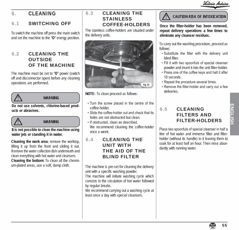
55
ENG
LISH6. CLEANING
6.1 SWITCHING OFF
6.2 CLEANING THE OUTSIDE
OF THE MACHINE
6.3 CLEANING THE STAINLESS
COFFEE-HOLDERS
6.4 CLEANING THE UNIT WITH
THE AID OF THE BLIND FILTER
To switch the machine off press the main switch and set the machine to the "O" energy position.
The machine must be set to “O” power (switch off and disconnector open) before any cleaning operations are performed.
Cleaning the work area: remove the worktop, lifting it up from the front and sliding it out. Remove the water collection dish underneath and clean everything with hot water and cleansers.Cleaning the bottom: To clean all the chromi-um-plated areas, use a soft, damp cloth.
The stainless coffee-holders are situated under the delivery units.
The machine is pre-set for cleaning the delivery unit with a specific washing powder. The machine will initiate washing cycle which consists in the circulation of hot water followed by regular breaks.We recommend carrying out a washing cycle at least once a day with special cleansers.
WARNING
WARNING
Do not use solvents, chlorine-based prod-ucts or abrasives.
It is not possible to clean the machine using water jets or standing it in water.
Fig. 22
NOTE: To clean proceed as follows:
coffee-holder.
holes are not obstructed but clean.
We recommend cleaning the coffee-holder once a week.
CAUTION RISK OF INTOXICATION
Once the filter-holder has been removed, repeat delivery operations a few times to eliminate any cleanser residues.
To carry out the washing procedure, proceed as follows:
blind filter.
powder and insert it into the unit filter-holder.
10 seconds.
deliveries.
6.5 CLEANING FILTERS AND
FILTER-HOLDERS
litre of hot water and immerse filter and filter-holder (without its handle) in it leaving them to soak for at least half an hour. Then rinse abun-dantly with running water.

56
ENG
LISH
moving it towards the left and allowing tube F to discharge the salty water until it has been eliminated and the water becomes fresh again (about half and hour).
Fig. 26
3) Reposition lever D towards the left.
Fig. 27
Fig. 24
Fig. 25
IN
OUT
7.1 RESIN AND SOFTENER REGENERATION
To avoid scaling deposits in the boiler and in the heating exchangers, the softener must always be kept efficient.Therefore, the ionic resins must be regularly regenerated.Regeneration times are established according to the quantity of coffee delivered daily and the hardness of the water utilisedThese can be seen in the diagram included in the following figure.
Regeneration procedures are as follows:1) Turn the machine off and place a container
large enough to contain at least 5 litres under tube E.
the cap off by unscrewing knob and fill with 1 Kg normal kitchen salt.
Fig. 23
7. MAINTENANCENOTE: During maintenance/repairs, the parts
used must be able to guarantee compli-ance with the safety and hygiene requirements envisaged for the device. Original replacement parts can offer this guarantee.
NOTE: After the repair or replacement of any components of parts that come into contact with food or water, it is neces-sary to carry out the washing procedure
to the manufacturer’s instructions.
C
C
F
C
G
E
D
C
D

57
ENG
LISH8. MACHINE FUNCTION MESSAGES
DISPLAY AND KEYINDICATIONS CAUSE EFFECT SOLUTION NOTE
DIAGNOSIS OF ERROR
At the time of the diagno-sis the system presents faults within the control unit functioning the water level
is not re-established.
DELIVERY ERROR
On reaching delivery time -
er doesn’t send out its set commands.
The display indicator and the ‘continuous’ key belong-ing to the relative unit will .
DOSER ERROR
If the doser doesn’t send out its set commands within
delivery onset.
If the delivery isn’t manu-ally halted, the maximum
blocked..
LEVEL ERROR functioning the water level is not re-established.
on and off. The pump is de-activated. The resistor and all
the functions are halted.
Turn the machine off and then turn it on again. All its functions will be re-activated.
PRESSURE ERRORWhen the machine’s tem-perature is higher than
130°C.
The display indicator will -
sistor is de-activated.
The system will be re-estab-lished as soon as the tem-perature goes below 130°C.
The boiler is provided with
is not re-established, call a
OVERCURRENT ERR.Incorrect electrical input caused by a malfunction in one of the machine charges.
The display reading will
off. The heating element and all other functions will
be disabled.
Switch off the machine and send for a specialist techni-
cal engineer.
FINE GRINDINGThe machine registers val-ues different from the set
values.A much longer delivery time.
Modify grinding degree and press the key RESET or
.
the programming state, with-in 10 minutes from the last selection, the system will re-
-ration and the display will in-dicate its reestablishment of
normal functioning.
COARSE GRINDINGThe machine registers val-ues different from the set
values.
A much shorter delivery time. .

58
ENG
LISH
NOTE______________________________________________________________________________
______________________________________________________________________________
______________________________________________________________________________
______________________________________________________________________________
______________________________________________________________________________
______________________________________________________________________________
______________________________________________________________________________
______________________________________________________________________________
______________________________________________________________________________
______________________________________________________________________________
______________________________________________________________________________
______________________________________________________________________________
______________________________________________________________________________
______________________________________________________________________________
______________________________________________________________________________

59
LEGENDA / KEY
MS Interruttore / Switch.R Relè / Relay.RS Relè statico / Relay.PM Motore pompa / Pump Motor.HE Resistenza boiler / Boiler heater ele-
ment.LP Sonda livello / Level probe.EV1 Elettrovalvola gruppo 1 / Electrovalve
group 1.EV2 Elettrovalvola gruppo 2 / Electrovalve
group 2.EV3 Elettrovalvola gruppo 3 / Electrovalve
group 3.EV4 Elettrovalvola gruppo 4 / Electrovalve
group 4.TE Termostato / Thermostat.EVHW Elettrovalvola miscelatore / Mixer elec-
trovalve.
P Pressostato / Pressure switch.EVS Elettrovalvola sfiato / Vacuum electro-
valve.RS1 Resistenza scaldatazze 1 / Cupwarmer
heating element 1.RS2 Resistenza scaldatazze 2 / Cupwarmer
heating element 2.ST1 Sonda temperatura scaldatazze 1 /
Cupwarmer temperature probe 1.ST2 Sonda temperatura scaldatazze 2 /
Cupwarmer temperature probe 2.SPC Sensore pressione caldaia / Boiler
pressure sensor.CRS Connettore relè statici / Static relays
connector.
EVL Elettrovalvola livello / Water level elec.STS1 Sonda temperatura scaldatazze 1 /
Cupwarmer temperature probe 1.STS2 Sonda temperatura scaldatazze 2 /
Cupwarmer temperature probe 2.LED Opzionale / optional.MS1 Interruttore LED (opzionale) / Switch
LED (optional).LED T Trasformatore LED (opzionale) /
Transformer LED (optional).
IMPIANTO ELETTRICO / ELECTRIC SYSTEMVA358 WHITE EAGLE 2 GR T3

60
LEGENDA / KEY
MS Interruttore / Switch.R Relè / Relay.RS Relè statico / Relay.PM Motore pompa / Pump Motor.HE Resistenza boiler / Boiler heater ele-
ment.LP Sonda livello / Level probe.EV1 Elettrovalvola gruppo 1 / Electrovalve
group 1.EV2 Elettrovalvola gruppo 2 / Electrovalve
group 2.EV3 Elettrovalvola gruppo 3 / Electrovalve
group 3.EV4 Elettrovalvola gruppo 4 / Electrovalve
group 4.TE Termostato / Thermostat.EVHW Elettrovalvola miscelatore / Mixer elec-
trovalve.
P Pressostato / Pressure switch.EVS Elettrovalvola sfiato / Vacuum electro-
valve.RS1 Resistenza scaldatazze 1 / Cupwarmer
heating element 1.RS2 Resistenza scaldatazze 2 / Cupwarmer
heating element 2.ST1 Sonda temperatura scaldatazze 1 /
Cupwarmer temperature probe 1.ST2 Sonda temperatura scaldatazze 2 /
Cupwarmer temperature probe 2.SPC Sensore pressione caldaia / Boiler
pressure sensor.CRS Connettore relè statici / Static relays
connector.
EVL Elettrovalvola livello / Water level elec.STS1 Sonda temperatura scaldatazze 1 /
Cupwarmer temperature probe 1.STS2 Sonda temperatura scaldatazze 2 /
Cupwarmer temperature probe 2.LED Opzionale / optional.MS1 Interruttore LED (opzionale) / Switch
LED (optional).LED T Trasformatore LED (opzionale) /
Transformer LED (optional).
IMPIANTO ELETTRICO / ELECTRIC SYSTEMVA358 WHITE EAGLE 3 GR T3

61
LEGENDA / KEY
MS Interruttore / Switch.R Relè / Relay.RS Relè statico / Relay.PM Motore pompa / Pump Motor.HE Resistenza boiler / Boiler heater ele-
ment.LP Sonda livello / Level probe.EV1 Elettrovalvola gruppo 1 / Electrovalve
group 1.EV2 Elettrovalvola gruppo 2 / Electrovalve
group 2.EV3 Elettrovalvola gruppo 3 / Electrovalve
group 3.EV4 Elettrovalvola gruppo 4 / Electrovalve
group 4.TE Termostato / Thermostat.EVHW Elettrovalvola miscelatore / Mixer elec-
trovalve.
P Pressostato / Pressure switch.EVS Elettrovalvola sfiato / Vacuum electro-
valve.RS1 Resistenza scaldatazze 1 / Cupwarmer
heating element 1.RS2 Resistenza scaldatazze 2 / Cupwarmer
heating element 2.ST1 Sonda temperatura scaldatazze 1 /
Cupwarmer temperature probe 1.ST2 Sonda temperatura scaldatazze 2 /
Cupwarmer temperature probe 2.SPC Sensore pressione caldaia / Boiler
pressure sensor.CRS Connettore relè statici / Static relays
connector.
EVL Elettrovalvola livello / Water level elec.STS1 Sonda temperatura scaldatazze 1 /
Cupwarmer temperature probe 1.STS2 Sonda temperatura scaldatazze 2 /
Cupwarmer temperature probe 2.LED Opzionale / optional.MS1 Interruttore LED (opzionale) / Switch
LED (optional).LED T Trasformatore LED (opzionale) /
Transformer LED (optional).
IMPIANTO ELETTRICO / ELECTRIC SYSTEMVA358 WHITE EAGLE DIGIT

62
LEGENDA / KEY
MS Interruttore / Switch.R Relè / Relay.RS Relè statico / Relay.PM Motore pompa / Pump Motor.HE Resistenza boiler / Boiler heater ele-
ment.LP Sonda livello / Level probe.EV1 Elettrovalvola gruppo 1 / Electrovalve
group 1.EV2 Elettrovalvola gruppo 2 / Electrovalve
group 2.EV3 Elettrovalvola gruppo 3 / Electrovalve
group 3.EV4 Elettrovalvola gruppo 4 / Electrovalve
group 4.TE Termostato / Thermostat.EVHW Elettrovalvola miscelatore / Mixer elec-
trovalve.
P Pressostato / Pressure switch.EVS Elettrovalvola sfiato / Vacuum electro-
valve.RS1 Resistenza scaldatazze 1 / Cupwarmer
heating element 1.RS2 Resistenza scaldatazze 2 / Cupwarmer
heating element 2.ST1 Sonda temperatura scaldatazze 1 /
Cupwarmer temperature probe 1.ST2 Sonda temperatura scaldatazze 2 /
Cupwarmer temperature probe 2.SPC Sensore pressione caldaia / Boiler
pressure sensor.CRS Connettore relè statici / Static relays
connector.
EVL Elettrovalvola livello / Water level elec.STS1 Sonda temperatura scaldatazze 1 /
Cupwarmer temperature probe 1.STS2 Sonda temperatura scaldatazze 2 /
Cupwarmer temperature probe 2.LED Opzionale / optional.MS1 Interruttore LED (opzionale) / Switch
LED (optional).LED T Trasformatore LED (opzionale) /
Transformer LED (optional).
IMPIANTO ELETTRICO / ELECTRIC SYSTEMVA358 WHITE EAGLE 2 GR T3 CSA

63
LEGENDA / KEY
MS Interruttore / Switch.R Relè / Relay.RS Relè statico / Relay.PM Motore pompa / Pump Motor.HE Resistenza boiler / Boiler heater ele-
ment.LP Sonda livello / Level probe.EV1 Elettrovalvola gruppo 1 / Electrovalve
group 1.EV2 Elettrovalvola gruppo 2 / Electrovalve
group 2.EV3 Elettrovalvola gruppo 3 / Electrovalve
group 3.EV4 Elettrovalvola gruppo 4 / Electrovalve
group 4.TE Termostato / Thermostat.EVHW Elettrovalvola miscelatore / Mixer elec-
trovalve.
P Pressostato / Pressure switch.EVS Elettrovalvola sfiato / Vacuum electro-
valve.RS1 Resistenza scaldatazze 1 / Cupwarmer
heating element 1.RS2 Resistenza scaldatazze 2 / Cupwarmer
heating element 2.ST1 Sonda temperatura scaldatazze 1 /
Cupwarmer temperature probe 1.ST2 Sonda temperatura scaldatazze 2 /
Cupwarmer temperature probe 2.SPC Sensore pressione caldaia / Boiler
pressure sensor.CRS Connettore relè statici / Static relays
connector.
EVL Elettrovalvola livello / Water level elec.STS1 Sonda temperatura scaldatazze 1 /
Cupwarmer temperature probe 1.STS2 Sonda temperatura scaldatazze 2 /
Cupwarmer temperature probe 2.LED Opzionale / optional.MS1 Interruttore LED (opzionale) / Switch
LED (optional).LED T Trasformatore LED (opzionale) /
Transformer LED (optional).
IMPIANTO ELETTRICO / ELECTRIC SYSTEMVA358 WHITE EAGLE 3 GR T3 CSA

64
LEGENDA / KEY
MS Interruttore / Switch.R Relè / Relay.RS Relè statico / Relay.PM Motore pompa / Pump Motor.HE Resistenza boiler / Boiler heater ele-
ment.LP Sonda livello / Level probe.EV1 Elettrovalvola gruppo 1 / Electrovalve
group 1.EV2 Elettrovalvola gruppo 2 / Electrovalve
group 2.EV3 Elettrovalvola gruppo 3 / Electrovalve
group 3.EV4 Elettrovalvola gruppo 4 / Electrovalve
group 4.TE Termostato / Thermostat.EVHW Elettrovalvola miscelatore / Mixer elec-
trovalve.
P Pressostato / Pressure switch.EVS Elettrovalvola sfiato / Vacuum electro-
valve.RS1 Resistenza scaldatazze 1 / Cupwarmer
heating element 1.RS2 Resistenza scaldatazze 2 / Cupwarmer
heating element 2.ST1 Sonda temperatura scaldatazze 1 /
Cupwarmer temperature probe 1.ST2 Sonda temperatura scaldatazze 2 /
Cupwarmer temperature probe 2.SPC Sensore pressione caldaia / Boiler
pressure sensor.CRS Connettore relè statici / Static relays
connector.
EVL Elettrovalvola livello / Water level elec.STS1 Sonda temperatura scaldatazze 1 /
Cupwarmer temperature probe 1.STS2 Sonda temperatura scaldatazze 2 /
Cupwarmer temperature probe 2.LED Opzionale / optional.MS1 Interruttore LED (opzionale) / Switch
LED (optional).LED T Trasformatore LED (opzionale) /
Transformer LED (optional).
IMPIANTO ELETTRICO / ELECTRIC SYSTEMVA358 WHITE EAGLE DIGIT CSA

65
SCHEMA IDRAULICO / HYDRAULIC DIAGRAMVA358 WHITE EAGLE DIGIT
LEGENDA / KEY
1 Rubinetto generale / General tap2 Pompa / Pump3 Valvola di ritegno / Retaining valve4 Valvola di espansione / Expansion valve 14-16 bar5 Elettrovalvola ugello / Refill electrovalve6 Dosatore volumetrico / Flowmeter7 Scambiatore di calore / Heater exchange8 Elettroval. Erogazione / Delivery electrovalve9 Valvola di sicurezza / Safely valve main boiler10 Elettroval. Acqua calda / Hot water electrovalve11 Rubinetto vapore / Steam tap
12 -13 Caldaia / Boiler14 Resistenza / Heating element15 -16 -17 -18 -19 Elettrovalvola vapore / Steam electrovalve20 Valvola anti risucchio / Antivacuum valve21 Sonda livello caldaia / Level probe22 Pressostato digitale / Digital pressostat23 Manometro / Manometer24 Pressostato meccanico / Mechanical pressostat

66
SCHEMA IDRAULICO / HYDRAULIC DIAGRAMVA358 WHITE EAGLE T3
LEGENDA / KEY
1 Rubinetto generale / General tap2 Pompa / Pump3 Valvola di ritegno / Retaining valve4 Valvola di espansione / Expansion valve 14-16 bar5 Elettrovalvola ugello / Refill electrovalve6 Dosatore volumetrico / Flowmeter7 Scambiatore di calore / Heater exchange8 Elettroval. Erogazione / Delivery electrovalve9 Valvola di sicurezza / Safely valve main boiler10 Elettroval. Acqua calda / Hot water electrovalve11 Rubinetto vapore / Steam tap
12 Caldaia caffè / Coffee boiler13 Caldaia / Boiler14 Resistenza / Heating element15 Valvola di sicurezza / Safely valve 12 bar16 Resistenza / Heating element17 Resistenza / Heating element18 -19 Elettrovalvola vapore / Steam electrovalve20 Valvola anti risucchio / Antivacuum valve21 Sonda livello caldaia / Level probe22 Pressostato digitale / Digital pressostat23 Manometro / Manometer24 Pressostato meccanico / Mechanical pressostat

67
List of Parts Liste des composants
Flange Pr machined, stainless steel +1 Flasque Pr finition inox +1
Flange 4 holes machined, stainless steel MicrobarFlasque 4 trous finition inox Microbar
Stainless steel pipe D.76.1 sp1.5 Aisi 316LTube inox D.76.1 ép.1.5 Aisi 316L
Heating element for welding 1000W 230VStainless steel version 2009 (Dwg. GGS63597)Résistance à souder 1000W 230V Inoxversion 2009 (Dessin GGS63597)
Stud M3x8 stainless steelBoulon prisonnier M3x8 inox
Bulb support tube microbar stainless steelTube porte-bulbe Microbar Inox
Stud M4x15 stainless steelBoulon prisonnier M4x15 Inox
STAINLESS STEEL
STAINLESS STEEL
STAINLESS STEEL
STAINLESS STEELAISI316L
STAINLESS STEELAISI316L
STAINLESS STEELAISI316L
Note: Boiler in application area, article 3, section 3 97/23/CENote: Chauffe-eau dans zone d’application article 3, alinéa 3 97/23/CE
Boiler Chaudière
Stainless steel Aisi 316LAcier inox Aisi 316L
MoyenneAveragemedia
Description Description
Description Description
Date Date
CodeDesignerConcepteur Code
PART NO.NUM. COMPOSANT
DESCRIPTIONDESCRIPTION
Material Matériau
TreatmentTraitement
ToleranceTolérance
ScaleEchelle
MATERIALMATERIAUQTE
QTYELEMENTELEMENT
2
3
4
1
7
7
5
6
SCHEMA CALDAIA / BOILER DIAGRAMVA358 WHITE EAGLE T3 (2 - 3 Gr.)

68
List of Parts Liste des composants
Boiler Chaudière
MoyenneAveragemedia
Description Description
Description Description
Date Date
CodeDesignerConcepteur Code
PART NO.NUM. COMPOSANT
DESCRIPTIONDESCRIPTION
Material Matériau
TreatmentTraitement
ToleranceTolérance
ScaleEchelle
MATERIALMATERIAUQTE
QTYELEMENTELEMENT
Cu-DHP 99.9CBoiler bodyCorps de la chaudière
orpo caldaia Aurelia 0016130
Cu-DHP 99.9CCup 2 holesCoupe 2 trous
oppa D.180 2 fori00010370
Cu-DHP 99.9TTubeTube
ubo scab D20X100161960
OT57 CW510LASteam outlet connection Attaque sortie de vapeur
ttacco presa vapore 00061871
OT57 CW510LGElbow fittingRaccord coudé
omito a saldare 3/8 M00061551
OT57 CW510LANippleAttaque mâle
ttacco 3/8'' Maschio00030251
OT57 CW510LANippleAttaque mâle
ttacco G1/4'' F passante 00030271
Cu-DHP 99.9CCup Coupe
oppa D.180 PR 201500016280
OT57 CW510LFFlange resistanceBride résistance
langia Resistenza 4 fori 201300063130
Rame,ottoneCopper, brassCuivre, brass
D.180 2Gr Aurelia II T3 OT57 2COPPE
90019510
45°
70°
31
70,2
180
Ø
180,5
390
1
3
6
2
3
5
5
202
3
3
4
7
4
4
7
7
7
7
100230
4625
30,20505°
465
9
8
65
1
1
2
3
2
1
5
1
1
8
9
SCHEMA CALDAIA / BOILER DIAGRAMVA358 WHITE EAGLE T3 2 GR

69
List of Parts Liste des composants
Boiler Chaudière
MoyenneAveragemedia
Description Description
Description Description
Date Date
CodeDesignerConcepteur Code
PART NO.NUM. COMPOSANT
DESCRIPTIONDESCRIPTION
Material Matériau
TreatmentTraitement
ToleranceTolérance
ScaleEchelle
MATERIALMATERIAUQTE
QTYELEMENTELEMENT
Cu-DHP 99.9CBoiler bodyCorps de la chaudière
orpo caldaia Aurelia 00161 00
Cu-DHP 99.9CCup 2 holesCoupe 2 trous
oppa D.180 2 fori00010370
Cu-DHP 99.9TTubeTube
ubo scab D20X100161960
OT57 CW510LASteam outlet connection Attaque sortie de vapeur
ttacco presa vapore 00061871
OT57 CW510LGElbow fittingRaccord coudé
omito a saldare 3/8 M00061551
OT57 CW510LANippleAttaque mâle
ttacco 3/8'' Maschio00030251
OT57 CW510LANippleAttaque mâle
ttacco G1/4'' F passante 00030271
Cu-DHP 99.9CCup Coupe
oppa D.180 PR 201500016280
OT57 CW510LFFlange resistanceBride résistance
langia Resistenza 4 fori 201300063130
Rame,ottoneCopper, brassCuivre, brass
D.180 Gr Aurelia II T33 2COPPE
90019510
1
1
3
3
2
1
1
1
8
9
60
210
663
50 545
180
Ø
45°
25°
31
70,2
70°
216
20Ø
8
1
5
7
73
7
2
5
5
4
4
2
6
6
6
202
620
25
30
330
100
5°
9
7
65
44
2
SCHEMA CALDAIA / BOILER DIAGRAMVA358 WHITE EAGLE T3 3 GR

70
List of Parts Liste des composants
Boiler Chaudière
MoyenneAveragemedia
Description Description
Description Description
Date Date
CodeDesignerConcepteur Code
PART NO.NUM. COMPOSANT
DESCRIPTIONDESCRIPTION
Material Matériau
TreatmentTraitement
ToleranceTolérance
ScaleEchelle
MATERIALMATERIAUQTE
QTYELEMENTELEMENT
Cu-DHP 99.9CBoiler bodyCorps de la chaudière
orpo caldaia Aurelia
Cu-DHP 99.9CCup 2 holesCoupe 2 trous
oppa D.180 2 fori00010370
Cu-DHP 99.9TTubeTube
ubo scab D54X100160170
OT57 CW510LASteam outlet connection Attaque sortie de vapeur
ttacco presa vapore 00061871
OT57 CW510LGElbow fittingRaccord coudé
omito a saldare 3/8 M00061551
OT57 CW510L
OT57 CW510L
A
Flangia chiusura Flange closureBride fermeture
NippleAttaque mâle
ttacco 3/8'' Maschio0
00061881
0030251
OT57 CW510LANippleAttaque mâle
ttacco G1/4'' F passante
00030271
Cu-DHP 99.9CCup Coupe
oppa D.180 PR 201500016280
OT57 CW510LFFlange resistanceBride résistance
langia Resistenza 4 fori 201300063130
Rame,ottoneCopper, brassCuivre, brass
D.180 2Gr Aurelia II 2COPPE
900195 00
1
1
2
3
2
1
4
110
7
1
1
8
9
45°
70°
31
70,2
180
Ø
25315
100230
180,5
390
210
216
5
5
5°
45° 30
65
25°
50 315 25
00015860
5
5
4
47
3
17
3
4
8
10
9
37
6
37
2
SCHEMA CALDAIA / BOILER DIAGRAMVA358 WHITE EAGLE 2 GR

71
List of Parts Liste des composants
Boiler Chaudière
MoyenneAveragemedia
Description Description
Description Description
Date Date
CodeDesignerConcepteur Code
PART NO.NUM. COMPOSANT
DESCRIPTIONDESCRIPTION
Material Matériau
TreatmentTraitement
ToleranceTolérance
ScaleEchelle
MATERIALMATERIAUQTE
QTYELEMENTELEMENT
Cu-DHP 99.9CBoiler bodyCorps de la chaudière
orpo caldaia Aurelia
Cu-DHP 99.9CCup 2 holesCoupe 2 trous
oppa D.180 2 fori00010370
Cu-DHP 99.9TTubeTube
ubo scab D54X100160170
OT57 CW510LASteam outlet connection Attaque sortie de vapeur
ttacco presa vapore 00061871
OT57 CW510LGElbow fittingRaccord coudé
omito a saldare 3/8 M00061551
OT57 CW510L
OT57 CW510L
A
Flangia chiusura Flange closureBride fermeture
NippleAttaque mâle
ttacco 3/8'' Maschio0
00061881
0030251
OT57 CW510L
ANippleAttaque mâle
ttacco G1/4'' F passante
00030271
Cu-DHP 99.9CCup Coupe
oppa D.180 PR 201500016280
OT57 CW510L
FFlange resistanceBride résistance
langia Resistenza 4 fori 201300063130
Rame,ottoneCopper, brassCuivre, brass
D.180 3Gr Aurelia II 2COPPE
900195 04
1
1
3
37
26
15
6
111
4
1
1
8
10
00016110
8
1
7
3
35
3
2
7
7
11
10
60 230 230 130
210
666
50 545 25
180
Ø
45°
25°
31
70,2
70°
210
216
54Ø
444
6
6
2
620
30
5°
65
66
444
2
SCHEMA CALDAIA / BOILER DIAGRAMVA358 WHITE EAGLE 3 GR

72
List of Parts Liste des composants
Boiler Chaudière
MoyenneAveragemedia
Description Description
Description Description
Date Date
CodeDesignerConcepteur Code
PART NO.NUM. COMPOSANT
DESCRIPTIONDESCRIPTION
Material Matériau
TreatmentTraitement
ToleranceTolérance
ScaleEchelle
MATERIALMATERIAUQTE
QTYELEMENTELEMENT
Cu-DHP 99.9CBoiler bodyCorps de la chaudière
orpo caldaia Aurelia
Cu-DHP 99.9CCup 2 holesCoupe 2 trous
oppa D.180 2 fori00010370
Cu-DHP 99.9TTubeTube
ubo scab D54X100160170
OT57 CW510LASteam outlet connection Attaque sortie de vapeur
ttacco presa vapore 00061871
OT57 CW510LGElbow fittingRaccord coudé
omito a saldare 3/8 M00061551
OT57 CW510L
OT57 CW510L
A
Flangia chiusura Flange closureBride fermeture
NippleAttaque mâle
ttacco 3/8'' Maschio0
00061881
0030251
OT57 CW510L
ANippleAttaque mâle
ttacco G1/4'' F passante
00030271
Cu-DHP 99.9CCup Coupe
oppa D.180 PR 201500016280
OT57 CW510L
FFlange resistanceBride résistance
langia Resistenza 4 fori 201300063130
Rame,ottoneCopper, brassCuivre, brass
D.180 3Gr Aurelia II 2COPPE
900195 04
1
1
3
38
27
16
8
113
5
1
1
11
12
00016500
1
3
5
68
11
12
13
25°
5°
45°
65
210
54Ø
216
41
50 775 25
210
60 230 230 230 100
180
70°
31
45°
70,2
0
850
25°30
8
2
81
5
3
8
12
11
13
6
SCHEMA CALDAIA / BOILER DIAGRAMVA358 WHITE EAGLE 4 GR

edir
.ro
Lauro Fioretti.Lauro Fioretti.Lauro Fioretti.
EC DECLARATION OF CONFORMITY DECLARATION DE CONFORMITE
DICHIARAZIONE DI CONFORMITÀ CE
Machinery Directive Directive machinesDirettiva macchine
Direttiva ROHS
Regolamento sulle buone pratiche di fabbricazione dei materiali e degli oggetti destinati a venire a contatto con prodotti alimentari G.U. L384 del22.12.2006, p.75. Guideline about good manufacturing practices of materials and articles destined to come into contact with foodstuffs – Commission Regulation L384 dated 22/12/2006, page 75. Règlement relatif aux bonnes pratiques de fabrication des matériaux et des objets destinés à entrer en contact avec des denrées alimentaires Journal Officiel Loi 384 du 22.12.2006, p.75.
Disciplina igienica degli imballaggi, recipienti, utensili, destinati a venire in contatto con le sostanze alimentari o con sostanze d'uso personale. Hygienic discipline regarding packaging, containers and utensils that are destined to come into contact with food substances or with substances of personal use. Discipline hygiénique des emballages, récipients, ustensiles, destinés à entrer en contact avec des denrées alimentaires ou avec des substances d’usage personnel.
(CE) No 2023/2006
D. M. 21/03/1973
10/2011/CEE
ROHS Directive Directive ROHS
direttiva materie plastiche plastics directive matériau plastique directive
85/572/CEE, 82/711/CEE direttive metalli e leghe metals and alloys directives métaux et alliages directives / directiva metales y aleaciones
Low Voltage Directive Directive basse tensionDirettiva bassa tensione
Directive for Materials and Articles intended to come into contact with foodstuffsDirective matériaux pour contact alimentaireDirettiva materiali per alimenti
Electromagnetic Compatibility DirectiveDirective compatibilité électromagnétiqueDirettiva compatibilità elettromagnetica
Pressurized Equipment Directive Directive équipements sous pressionDirettiva attrezzature a pressione

Norme applicate: Raccolte M,S, VSR edizione '78 e '95 conservate presso la sede legale.Applied regulations: Collections M,S, VSR editions '78 and '95 and available in the registered office.Normes appliquées: Recalte M, S, VSR edition '78 et '95 gardées chez la siège légal.
Disegno n°: (Vedi parte finale del Libretto Istruzioni)Drawing No. (See the end of the Instruction Booklet)Dessin n°: (Voir la fin du livret d'instructions)
Amministratore delegato
EC DECLARATION OF CONFORMITY PRESSURE EQUIPMENT DECLARATION DE CONFORMITE MACHINE SOUS PRESSION
DICHIARAZIONE DI CONFORMITÀ CE ATTREZZATURA A PRESSIONE
ATTENZIONE: La presente dichiarazione va conservata e deve accompagnare sempre l'attrezzatura. Ogni uso dell'attrezzatura diverso da quello previsto dalprogetto é vietato. L'integrità e l'efficienza dell'attrezzatura e degli accessori di sicurezza sono a cura dell'utente. La presente dichiarazione perde la sua validità nelcaso in cui l’apparecchio venga modificato senza espressa autorizzazione del costruttore oppure se installato o utilizzato in modo non conforme a quanto indicatonel manuale d’uso e nelle istruzioni.
ATTENTION: This declaration is to be kept with the equipment at all times and must always go together with the equipment. Any use of the equipment than forthe purposes for which it was designed is prohibited. The integrity and efficiency of the equipment of the safety devices are the responsibility of the user. Thedeclaration is null and void if the machine is modified without the express authorization of the manufacturer or if improperly installed and used in such a way thatdoes not comply with indications in the user’s manual and the instructions.
ATTENTION: Cette déclaration doit être conservée et doit toujours aller avec la machine. Toute utilisation de la machine différente de celle qui este prévue par leprojet est interdite. L'intégrité et l'efficacité de la machine et des accessoires de sécurité sont à la charge de l'utilisateur. La présente déclaration perd toute validitédans le cas où l'appareil est modifié sans l'autorisation du constructeur ou si l'appareil est installé ou utilisé de façon non conforme à ce qui est indiqué dans lemanuel et dans le mode d'emploi.
* Boiler in zona di applicazione articolo 3, comma 3 97/23/CE * Boiler in application area, article 3, section 3 97/23/EC* Chauffe-eau en zone d’application article 3, alinéa 3 97/23/CE
Caldaia e:
12/01/2015
Ottavi Nando


Via Madonna d’Antegiano, 662020 Belforte del Chienti
Macerata ItalyTel. +39.0733.950243Fax +39.0733.950247
www.victoriaarduino.com E-mail: [email protected]
Graphics and printing by: TYPE ENGINEERING S.r.l.
Codic
e 31
0006
35
01_0
2/201
6
Victoria Arduino si riserva di apportare tutte le modifiche ritenute necessarie.
More info