Embed Size (px)
Citation preview
Wireless USB Adaptor
MODEL USB‐ADG‐2
LINUX USER GUIDE Version 1.0
LIMITED WARRANTY AIR802 guarantees that each USB‐ADG‐2 will be free from physical defects in material and workmanship under normal use for two (2) years from the date of purchase. If the product proves defective during this two‐year warranty period, call AIR802 Technical Support in order to obtain a Return Authorization Number. BE SURE TO HAVE YOUR PROOF OF PURCHASE AND A BARCODE FROM THE PRODUCT’S PACKAGING PRIOR TO CALLING. RETURN REQUESTS CAN NOT BE PROCESSED WITHOUT PROOF OF PURCHASE. When returning a product, mark the Return Authorization number clearly on the outside of the package and include a copy of your original proof of purchase. All customers outside of the United States of America and Canada shall be held responsible for shipping charges and handling charges.
IN NO EVENT SHALL AIR802’S LIABILITY EXCEED THE PRICE PAID FOR THE PRODUCT FROM DIRECT, INDIRECT, SPECIAL, INCIDENTAL, OR CONSEQUENTIAL DAMAGES RESULTING FROM THE USE OF THE PRODUCT, ITS ACCOMPANYING SOFTWARE, OR ITS DOCUMENTATION. AIR802 DOES NOT OFFER ANY REFUNDS FOR THE USB‐ADG‐2 PRODUCT UNLESS IT WAS PURCHASED VIA THE AIR8O2 ONLINE STORE AND THEN THE STORE POLICIES SHALL APPLY. AIR802 makes no warranty or representation, expressed, implied, or statutory, with respect to its products or use of this documentation and all accompanying software, and specficially disclaims its quality, performance, merchantibility, or fitness for any particular purpose. AIR802 reserves the right to revise or update its products, software, or documentation without obligation to notfify any individual or entity. Please direct all inquires to:
AIR802 Suite 137‐319 931 West 75th Street Naperville, IL 60540.
FCC STATEMENT This USB Adaptor has been tested and complies with the specifications for a Class B digital devices, pursuant to Part 15 of the FCC Rules. These limits are designed to provide reasonable protection against harmful interference in a residential installation. This equipment generates, uses, and can radiate radio frequency energy and, if not installed and used according to the instructions, may cause harmful interference to radio communications. However, there is no guarantee that interference will not occur in a particular installation. If this equipment does cause harmful interference to radio or television reception, which is found by turning the equipment off and on, the user is encouraged to try and correct the interference by one or more of the following measures:
1. Reorient or relocate the receiving antenna 2. Increase the separation between the equipment and receiver. 3. Connect the equipment into an outlet on a circuit different from that to which the receiver is connected. 4. Consult the dealer or an experienced radio technician for assistance.
FCC Caution Any changes or modifications nor expressly approved by the party responsible for compliance could void the user’s authority to operate this equipment.
This device complies with Part 15 of the FCC Rules. Operation is subject to the following two conditions: (1) This device may not cause harmful interference, and (2) this device must not accept any interference received, including interference that may cause undesired operation.
FCC RF Radiation Exposure Statement This equipment complies with FCC radiation exposure set forth for an uncontolled environment. This equipment should be installed and operated with minimum distance 20 cm between the radiator and your body. Users can purchase USB extension cables if necessary to comply.
The device and its antenna must not be co‐located or operating in conjunction with any other antenna or transmitter.
TABLE OF CONTENTS
Chapter 1: Introduction 1 USB Adaptor Introduction 1 Features 1 System Requirements 1 Package Contents 2 Chapter 2: Network Planning & Architecture 2 Ad‐Hoc versus Infrastructure Mode 2 USB Extension Cables 3 Alternative Antennas 4 Applications 5 Chapter 3: Installation 11 Preparation Requirements 11 Packaging Extraction 11 Build and Install Drivers 12 Configure the Wireless Settings 13 Setup Linux WPA Supplicant 19 ZyDAS Turbo Mode 23 Appendix A: Glossary 24 Appendix B: Specifications 27 Appendix C: Warranty Information 28 Appendix F: Contact Information 28
CHAPTER 1: INTRODUCTION
USB ADAPTOR INTRODUCTION Thank you for your purchase of the AIR802 USB‐ADG‐2 adaptor. This USB adaptor offers great value whether you are an individual purchasing for use at home or for use in a business of any size.
USB adaptors are a simple and easy way to add wireless to a computer. The majority of computers now ship with wireless cards built‐in, but users commonly find weak signals. This weak signal can occur due to several factors. One it may be too far from a wireless router or access point, most internal wireless cards do not provide significant radio frequency (RF) gain. Another factor is that almost all built‐in cards have the antennas operating horizontally, where the wireless router or access point has vertically polarized antennas. This results in significant signal loss. Whatever the resulting cause of the weak signal is, the USB‐ADG‐2 with its external and removable antenna will enhance your wireless experience. This key to successful wireless exerience is the external and removable antenna with the flexibility of using alternative antennas.
The compact design makes it easy for you to travel with the adaptor. It draws its power from the USB port, so you do not need an external power supply.
As with all USB stick type devices care should be taken while connected to a laptop.
FEATURES • Compact Size • USB 1.1 and 2.0 Compliant • Modulation Method: IEEE 802.11b: DSS (Direct Sequence Spread Spectrum) IEEE 802.11g: OFDM (Ortho Frequency Division Multiplexing) • Easy Setup and Operation • Powered by Host Computer • Basic to Superior Security Encryption: 64‐bit, 128‐bit or 256‐bit WEP; WPA and WPA2 • 54/48/36/24/18/12/11/9/6/5.5/1 Mbps Selectable Data Rate • Supports WMM™ (Wi‐Fi Multimedia) Function • 2400 to 2485 MHz unlicensed ISM Frequency Band • 2‐Year Limited Warranty
SYSTEM REQUIREMENTS • Kernel 2.4.20+ : The driver has been successfully and easily built in Redhat9, Fedora Core2.3 and Debian 3. 1.
1
PACKAGE CONTENTS • USB Adaptor • Antenna (5dBi gain) • CD (Driver/Utility/User’s Manual)
CHAPTER 2: NETWORK PLANNING AND ARCHITECTURE
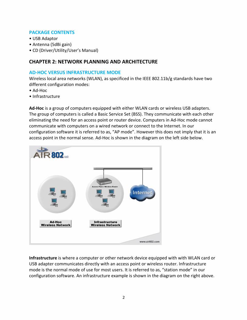
AD‐HOC VERSUS INFRASTRUCTURE MODE Wireless local area networks (WLAN), as specificed in the IEEE 802.11b/g standards have two different configuration modes: • Ad‐Hoc • Infrastructure Ad‐Hoc is a group of computers equipped with either WLAN cards or wireless USB adapters. The group of computers is called a Basic Service Set (BSS). They communicate with each other eliminating the need for an access point or router device. Computers in Ad‐Hoc mode cannot communicate with computers on a wired network or connect to the Internet. In our configuration software it is referred to as, “AP mode”. However this does not imply that it is an access point in the normal sense. Ad‐Hoc is shown in the diagram on the left side below.
Infrastructure is where a computer or other network device equipped with with WLAN card or USB adapter communicates directly with an access point or wireless router. Infrastructure mode is the normal mode of use for most users. It is referred to as, “station mode” in our configuration software. An infrastructure example is shown in the diagram on the right above.
2
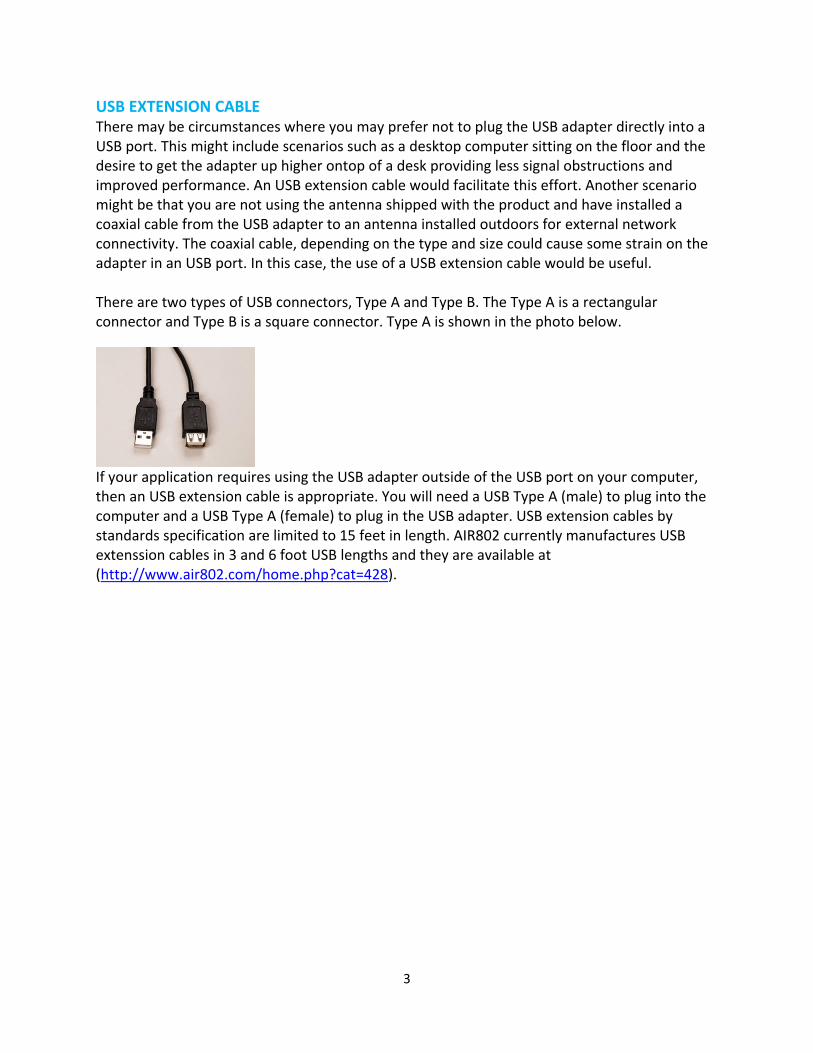
USB EXTENSION CABLE There may be circumstances where you may prefer not to plug the USB adapter directly into a USB port. This might include scenarios such as a desktop computer sitting on the floor and the desire to get the adapter up higher ontop of a desk providing less signal obstructions and improved performance. An USB extension cable would facilitate this effort. Another scenario might be that you are not using the antenna shipped with the product and have installed a coaxial cable from the USB adapter to an antenna installed outdoors for external network connectivity. The coaxial cable, depending on the type and size could cause some strain on the adapter in an USB port. In this case, the use of a USB extension cable would be useful. There are two types of USB connectors, Type A and Type B. The Type A is a rectangular connector and Type B is a square connector. Type A is shown in the photo below.
If your application requires using the USB adapter outside of the USB port on your computer, then an USB extension cable is appropriate. You will need a USB Type A (male) to plug into the computer and a USB Type A (female) to plug in the USB adapter. USB extension cables by standards specification are limited to 15 feet in length. AIR802 currently manufactures USB extenssion cables in 3 and 6 foot USB lengths and they are available at (http://www.air802.com/home.php?cat=428).
3
ALTERNATIVE ANTENNAS The USB‐ADG‐2 is sold with a 5dBi gain dipole type antena. This antenna radiates radio frequency (RF) in 360 degrees. Users may depending on their application and needs find alternative antennas to be useful. AIR802 manufactures a wide range of antennas which could be used with this adapter. Antennas alone do not determine the distance that you may reach. It is a factor of the RF transmit power and receiver sensitivity (with the USB adapter and the access point/router device), any cabling loss, free space loss and antenna gain and other factors such as interference in the 2.4 GHz ISM band. With line‐of‐sight, antennnas and a proper installation, a point‐to‐point network can be achieved for 1 mile or more. Outdoor antennas can be used indoors and will almost always will provide better results than an indoor antenna of the same gain. To install an antenna remote of the USB adapter, you will need to purchase a special AIR802 antenna cable asssembly. The cable assembly will require a RP‐SMA (plug) at the USB adapter end. AIR802 outdoor antennas will require a N(male) connector at the opposite end of the cabe. Indoor Type • ANOM2409‐RPSMA Dipole antenna with 9dBi gain – use if higher gain is required • ANOM2406 Directional 6dBi gain – use to focus RF energy in a specific direction • ANOM2448 Directional 4.8dBi gain, with 100cm (7.87”) cable – use for directional gain Outdoor Type *Requires AIR802 Antenna Cable Assembly • ANOM2408 Omnidirectional (360 degree), 8dBi gain, Outdoor • ANOM2410 Omnidirectional (360 degree), 10dBi gain, Outdoor • ANOM2412 Omnidirectional (360 degree), 12dBi gain, Outdoor • ANYA2408 Yagi (directional), 8dBi gain, Outdoor • ANYA2410 Yagi (directional), 10dBi gain, Outdoor • ANYA2412 Yagi (directional), 12dBi gain, Outdoor • ANYA2415 Yagi (directional), 15dBi gain, Outdoor • ANYA2418 Yagi (directional), 18dBi gain, Outdoor
4
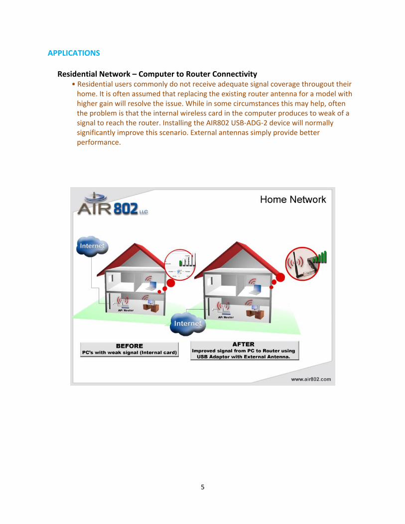
APPLICATIONS Residential Network – Computer to Router Connectivity
• Residential users commonly do not receive adequate signal coverage througout their home. It is often assumed that replacing the existing router antenna for a model with higher gain will resolve the issue. While in some circumstances this may help, often the problem is that the internal wireless card in the computer produces to weak of a signal to reach the router. Installing the AIR802 USB‐ADG‐2 device will normally significantly improve this scenario. External antennas simply provide better performance.
5
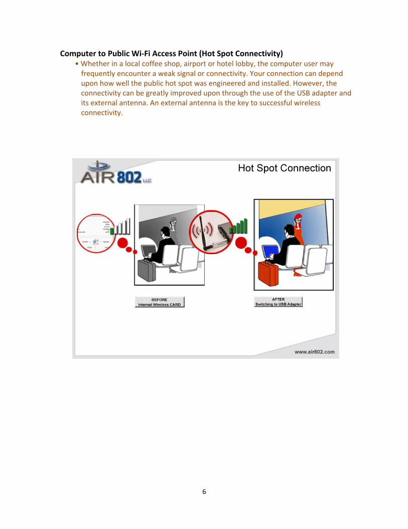
Computer to Public Wi‐Fi Access Point (Hot Spot Connectivity) • Whether in a local coffee shop, airport or hotel lobby, the computer user may
frequently encounter a weak signal or connectivity. Your connection can depend upon how well the public hot spot was engineered and installed. However, the connectivity can be greatly improved upon through the use of the USB adapter and its external antenna. An external antenna is the key to successful wireless connectivity.
6
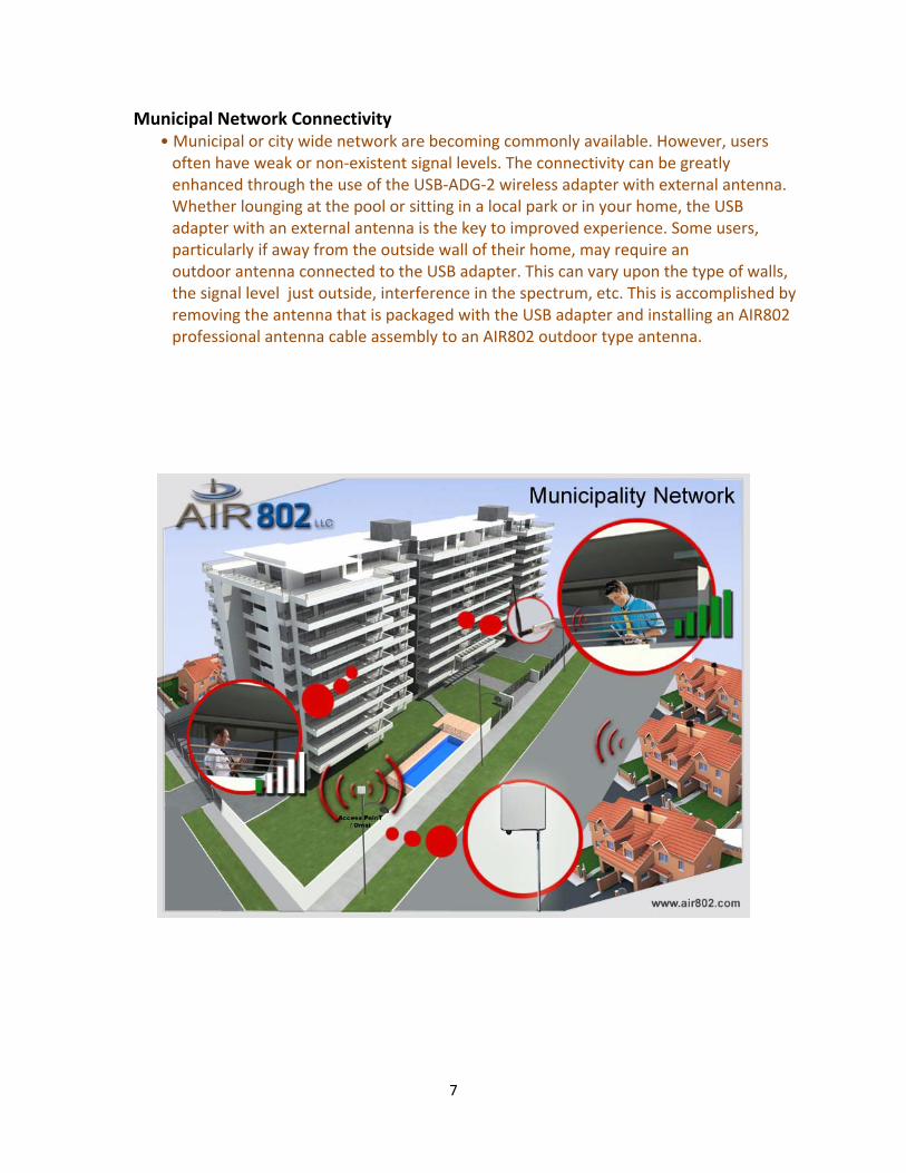
Municipal Network Connectivity • Municipal or city wide network are becoming commonly available. However, users often have weak or non‐existent signal levels. The connectivity can be greatly enhanced through the use of the USB‐ADG‐2 wireless adapter with external antenna. Whether lounging at the pool or sitting in a local park or in your home, the USB adapter with an external antenna is the key to improved experience. Some users, particularly if away from the outside wall of their home, may require an outdoor antenna connected to the USB adapter. This can vary upon the type of walls, the signal level just outside, interference in the spectrum, etc. This is accomplished by removing the antenna that is packaged with the USB adapter and installing an AIR802 professional antenna cable assembly to an AIR802 outdoor type antenna.
7
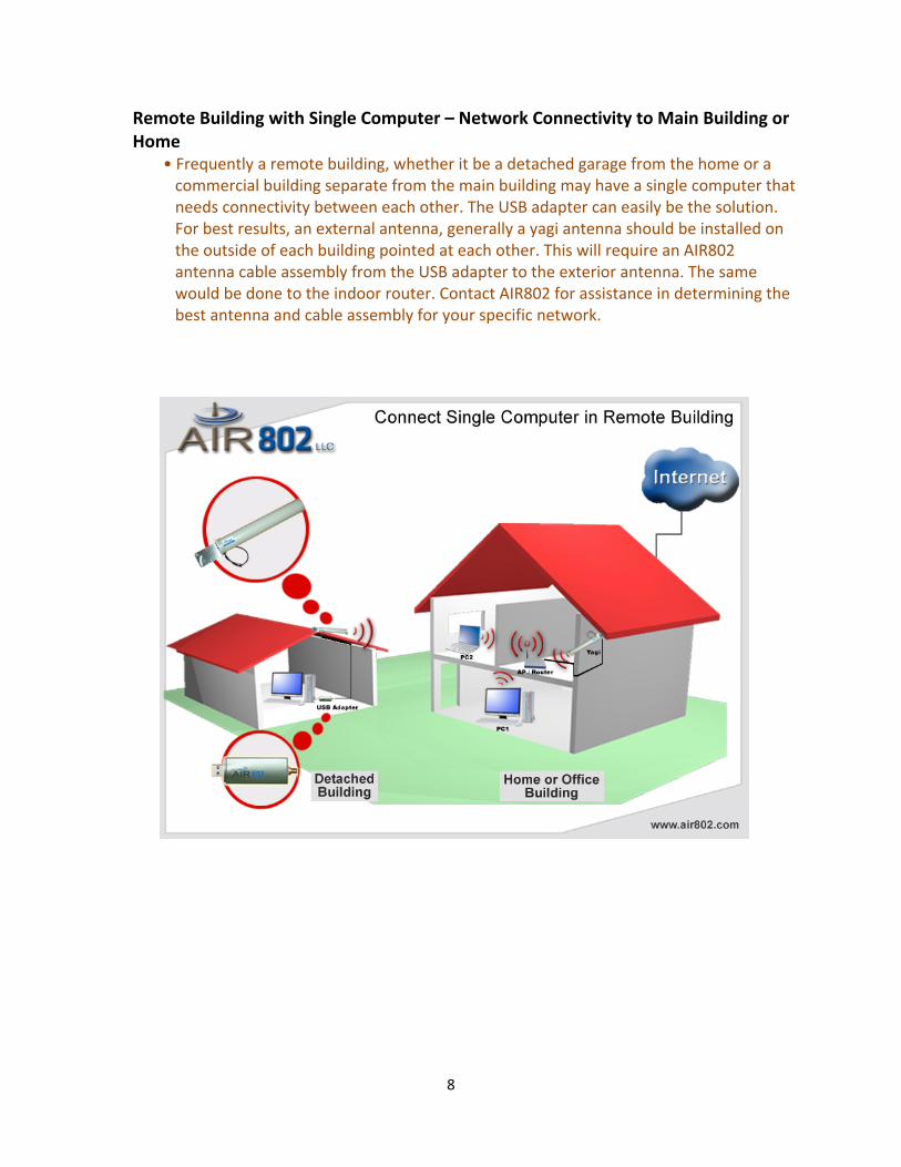
Remote Building with Single Computer – Network Connectivity to Main Building or Home
• Frequently a remote building, whether it be a detached garage from the home or a commercial building separate from the main building may have a single computer that needs connectivity between each other. The USB adapter can easily be the solution. For best results, an external antenna, generally a yagi antenna should be installed on the outside of each building pointed at each other. This will require an AIR802 antenna cable assembly from the USB adapter to the exterior antenna. The same would be done to the indoor router. Contact AIR802 for assistance in determining the best antenna and cable assembly for your specific network.
8
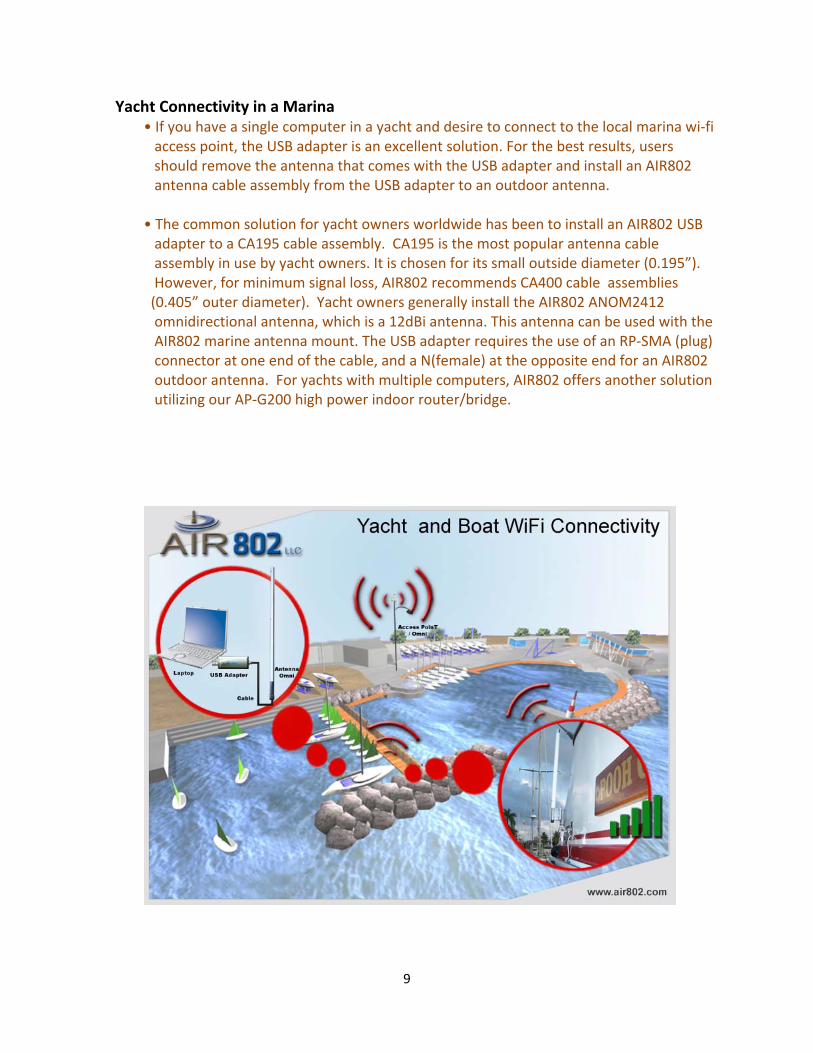
Yacht Connectivity in a Marina • If you have a single computer in a yacht and desire to connect to the local marina wi‐fi access point, the USB adapter is an excellent solution. For the best results, users should remove the antenna that comes with the USB adapter and install an AIR802 antenna cable assembly from the USB adapter to an outdoor antenna. • The common solution for yacht owners worldwide has been to install an AIR802 USB adapter to a CA195 cable assembly. CA195 is the most popular antenna cable assembly in use by yacht owners. It is chosen for its small outside diameter (0.195”). However, for minimum signal loss, AIR802 recommends CA400 cable assemblies (0.405” outer diameter). Yacht owners generally install the AIR802 ANOM2412 omnidirectional antenna, which is a 12dBi antenna. This antenna can be used with the AIR802 marine antenna mount. The USB adapter requires the use of an RP‐SMA (plug) connector at one end of the cable, and a N(female) at the opposite end for an AIR802 outdoor antenna. For yachts with multiple computers, AIR802 offers another solution utilizing our AP‐G200 high power indoor router/bridge.
9
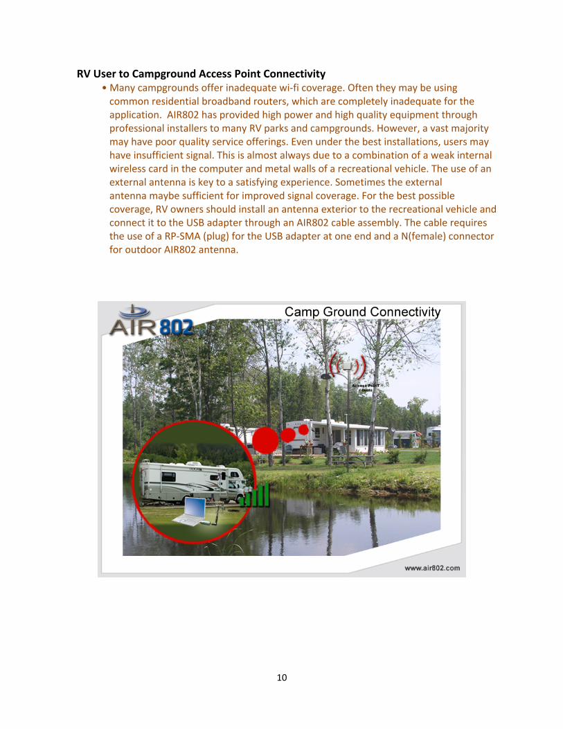
RV User to Campground Access Point Connectivity • Many campgrounds offer inadequate wi‐fi coverage. Often they may be using common residential broadband routers, which are completely inadequate for the application. AIR802 has provided high power and high quality equipment through professional installers to many RV parks and campgrounds. However, a vast majority may have poor quality service offerings. Even under the best installations, users may have insufficient signal. This is almost always due to a combination of a weak internal wireless card in the computer and metal walls of a recreational vehicle. The use of an external antenna is key to a satisfying experience. Sometimes the external antenna maybe sufficient for improved signal coverage. For the best possible coverage, RV owners should install an antenna exterior to the recreational vehicle and connect it to the USB adapter through an AIR802 cable assembly. The cable requires the use of a RP‐SMA (plug) for the USB adapter at one end and a N(female) connector for outdoor AIR802 antenna.
10
CHAPTER 3: INSTALLATION AIR802 recognizes that more and more users are installing the Linux operating system. Therefore we are pleased to support those users with our USB-ADG-2 802.11b/g adapter. 3.1 PREPARATION REQUIREMENTS
1. Kernel 2.4.20+ (The driver has been successfully and easily built in Redhat9, Fedora Core2.3 and Debian 3.1)
2. You will need a configured kernel source code for the kernel that you are running – ideally this will mean that you have at least run ‘make config’, ‘make menuconfig’, or ‘make xconfig’. Note: If your platform is not a SMP system, do not set SMP as supported. If you do, when the module is loaded, it will create an unresolved symbol.
3. Make sure that your kernel usb 2.0 support is running. Note 1: Use lsmod to check if “ehci-hcd module is loaded. Note 2: If host does not support usb 2.0, the USB-ADG-2 will run under pure-b mode.
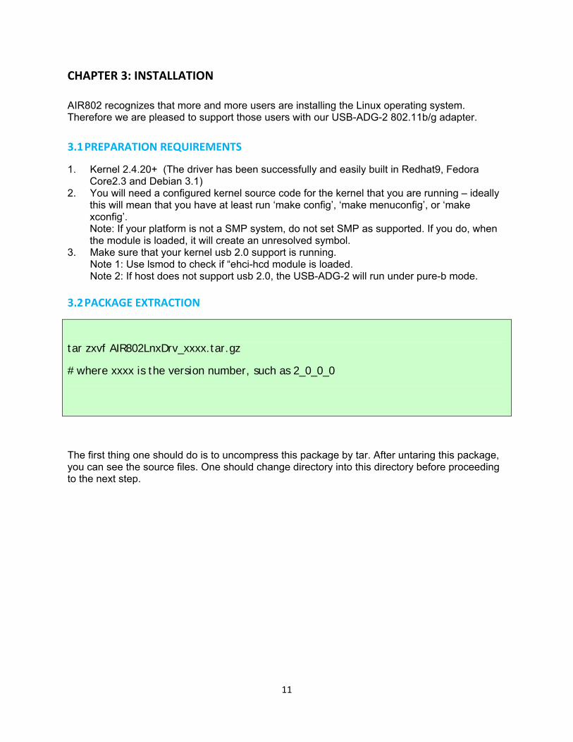
3.2 PACKAGE EXTRACTION
tar zxvf AIR802LnxDrv_xxxx.tar.gz
# where xxxx is the version number, such as 2_0_0_0
The first thing one should do is to uncompress this package by tar. After untaring this package, you can see the source files. One should change directory into this directory before proceeding to the next step.
11
3.3 BUILD AND INSTALL THE DRIVER
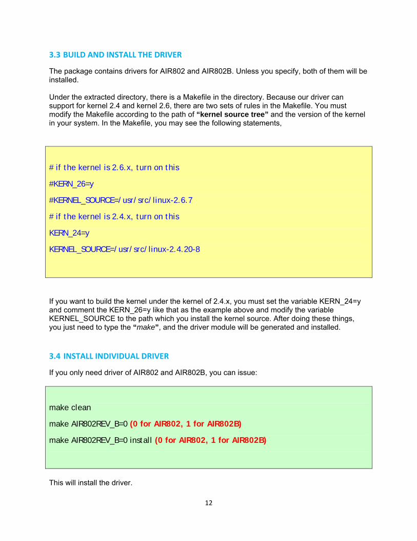
The package contains drivers for AIR802 and AIR802B. Unless you specify, both of them will be installed. Under the extracted directory, there is a Makefile in the directory. Because our driver can support for kernel 2.4 and kernel 2.6, there are two sets of rules in the Makefile. You must modify the Makefile according to the path of “kernel source tree” and the version of the kernel in your system. In the Makefile, you may see the following statements,
# if the kernel is 2.6.x, turn on this
#KERN_26=y
#KERNEL_SOURCE=/usr/src/linux-2.6.7
# if the kernel is 2.4.x, turn on this
KERN_24=y
KERNEL_SOURCE=/usr/src/linux-2.4.20-8
If you want to build the kernel under the kernel of 2.4.x, you must set the variable KERN_24=y and comment the KERN_26=y like that as the example above and modify the variable KERNEL_SOURCE to the path which you install the kernel source. After doing these things, you just need to type the “make”, and the driver module will be generated and installed. 3.4 INSTALL INDIVIDUAL DRIVER
If you only need driver of AIR802 and AIR802B, you can issue:
make clean
make AIR802REV_B=0 (0 for AIR802, 1 for AIR802B)
make AIR802REV_B=0 install (0 for AIR802, 1 for AIR802B)
This will install the driver.
12
3.5 BUILD THE DEBUGGING TOOL
There are two debugging tools in this package, “apdbg” and “menudbg”. Run “make debug” to compile them both. If you don’t have the ncurse library, you may get some error messages while compiling menudbg. You can ignore it and get apdbg only. 3.6 LOAD THE DRIVER
Generally, the driver is automatically loaded when the AIR802 dongle is inserted. If not, you may use the modprobe –v AIR802(or AIR802) to load our driver. In order to check whether our driver is loaded successfully, one can use the “lsmod” for this check. If our driver is loaded successfully, the following messages should be seen ... AIR802 183576 0 (unused) ... Please note that the 183576 may not be the same as that in your system. 3.7 OPEN THE NETWORK INTERFACE
In our driver, we will stop all the commands until the network interface assigned to us is opened. You can open the network interface by the following command ]$ ifconfig ethX up or ]$ ifconfig ethX <IP address> 3.8 CONFIGURE THE WIRELESS SETTINGS
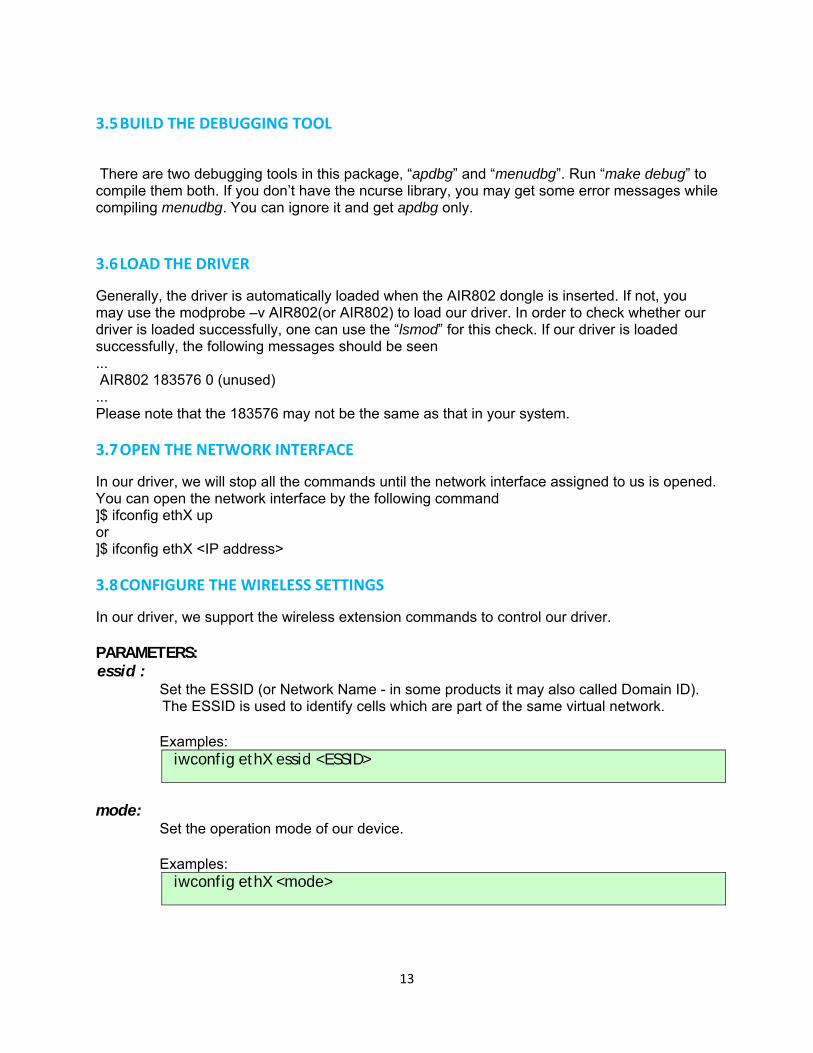
In our driver, we support the wireless extension commands to control our driver. PARAMETERS: essid :
Set the ESSID (or Network Name - in some products it may also called Domain ID). The ESSID is used to identify cells which are part of the same virtual network. Examples: iwconfig ethX essid <ESSID>
mode:
Set the operation mode of our device. Examples: iwconfig ethX <mode>
13
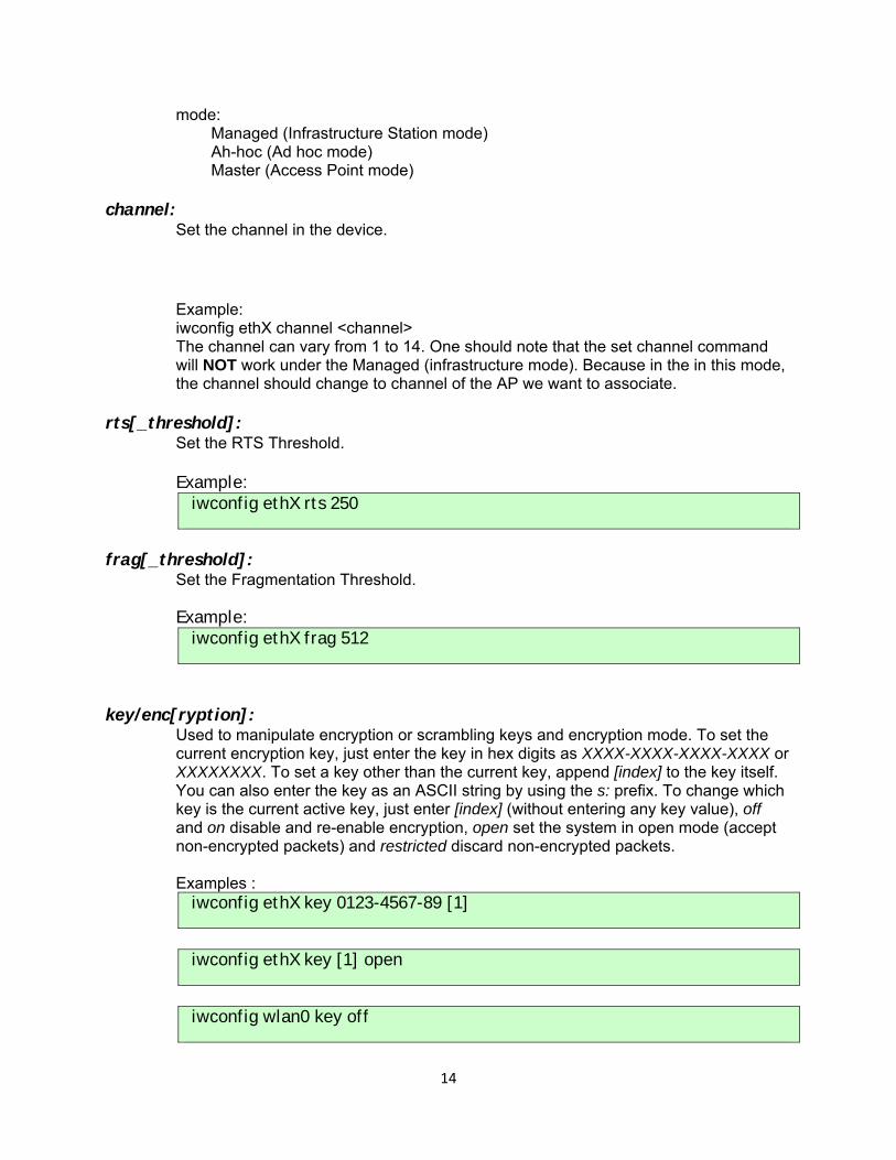
mode: Managed (Infrastructure Station mode) Ah-hoc (Ad hoc mode) Master (Access Point mode)
channel:
Set the channel in the device.
Example: iwconfig ethX channel <channel> The channel can vary from 1 to 14. One should note that the set channel command will NOT work under the Managed (infrastructure mode). Because in the in this mode, the channel should change to channel of the AP we want to associate.
rts[_threshold]: Set the RTS Threshold. Example: iwconfig ethX rts 250
frag[_threshold]:
Set the Fragmentation Threshold. Example: iwconfig ethX frag 512
key/enc[ryption]: Used to manipulate encryption or scrambling keys and encryption mode. To set the current encryption key, just enter the key in hex digits as XXXX-XXXX-XXXX-XXXX or XXXXXXXX. To set a key other than the current key, append [index] to the key itself. You can also enter the key as an ASCII string by using the s: prefix. To change which key is the current active key, just enter [index] (without entering any key value), off and on disable and re-enable encryption, open set the system in open mode (accept non-encrypted packets) and restricted discard non-encrypted packets. Examples : iwconfig ethX key 0123-4567-89 [1]
iwconfig ethX key [1] open
iwconfig wlan0 key off
14
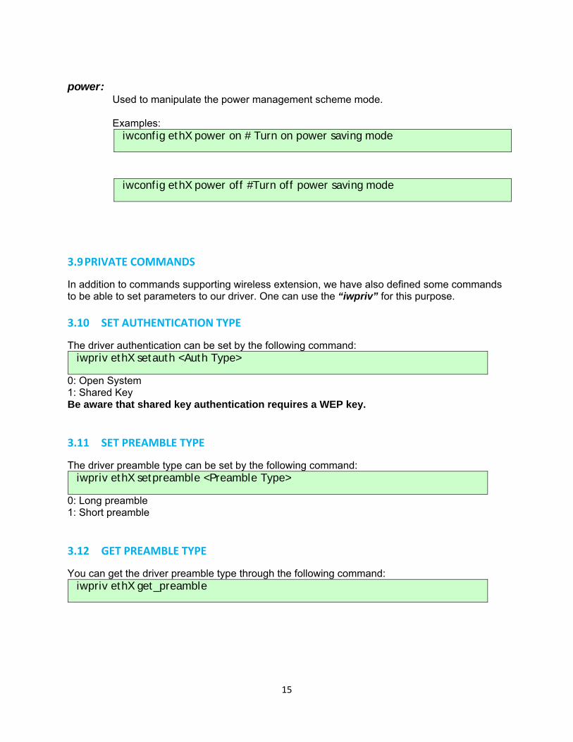
power:
Used to manipulate the power management scheme mode. Examples: iwconfig ethX power on # Turn on power saving mode
iwconfig ethX power off #Turn off power saving mode
3.9 PRIVATE COMMANDS
In addition to commands supporting wireless extension, we have also defined some commands to be able to set parameters to our driver. One can use the “iwpriv” for this purpose.
3.10 SET AUTHENTICATION TYPE
The driver authentication can be set by the following command: iwpriv ethX setauth <Auth Type>
0: Open System 1: Shared Key Be aware that shared key authentication requires a WEP key.
3.11 SET PREAMBLE TYPE
The driver preamble type can be set by the following command: iwpriv ethX setpreamble <Preamble Type>
0: Long preamble 1: Short preamble
3.12 GET PREAMBLE TYPE
You can get the driver preamble type through the following command: iwpriv ethX get_preamble
15
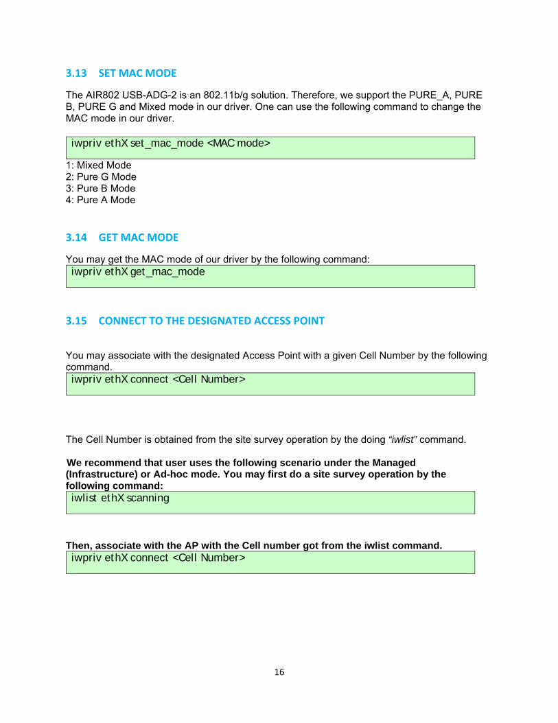
3.13 SET MAC MODE
The AIR802 USB-ADG-2 is an 802.11b/g solution. Therefore, we support the PURE_A, PURE B, PURE G and Mixed mode in our driver. One can use the following command to change the MAC mode in our driver. iwpriv ethX set_mac_mode <MAC mode>
1: Mixed Mode 2: Pure G Mode 3: Pure B Mode 4: Pure A Mode
3.14 GET MAC MODE
You may get the MAC mode of our driver by the following command: iwpriv ethX get_mac_mode
3.15 CONNECT TO THE DESIGNATED ACCESS POINT
You may associate with the designated Access Point with a given Cell Number by the following command. iwpriv ethX connect <Cell Number>
The Cell Number is obtained from the site survey operation by the doing “iwlist” command. We recommend that user uses the following scenario under the Managed (Infrastructure) or Ad-hoc mode. You may first do a site survey operation by the following command: iwlist ethX scanning
Then, associate with the AP with the Cell number got from the iwlist command. iwpriv ethX connect <Cell Number>
16
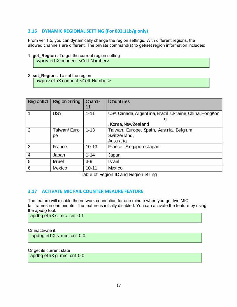
3.16 DYNAMIC REGIONAL SETTING (For 802.11b/g only)
From ver 1.5, you can dynamically change the region settings. With different regions, the allowed channels are different. The private command(s) to get/set region information includes: 1. get_Region : To get the current region setting
iwpriv ethX connect <Cell Number>
2. set_Region : To set the region
iwpriv ethX connect <Cell Number>
RegionID1 Region String Chan1-
11 lCountries
1 USA 1-11 USA,Canada,Argentina,Brazil,Ukraine,China,HongKong
,Korea,NewZealand 2 Taiwan/Euro
pe 1-13 Taiwan, Europe, Spain, Austria, Belgium,
Switzerland, Australia
3 France 10-13 France, Singapore Japan
4 Japan 1-14 Japan 5 Israel 3-9 Israel 6 Mexico 10-11 Mexico
Table of Region ID and Region String
3.17 ACTIVATE MIC FAIL COUNTER MEAURE FEATURE
The feature will disable the network connection for one minute when you get two MIC fail frames in one minute. The feature is initially disabled. You can activate the feature by using the apdbg tool. apdbg ethX s_mic_cnt 0 1
Or inactivate it. apdbg ethX s_mic_cnt 0 0
Or get its current state apdbg ethX g_mic_cnt 0 0
17
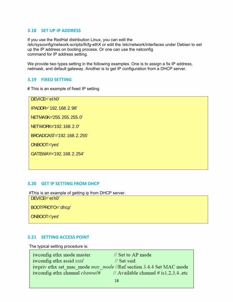
3.18 SET UP IP ADDRESS
If you use the RedHat distribution Linux, you can edit the /etc/sysconfig/network-scripts/ifcfg-ethX or edit the /etc/network/interfaces under Debian to set up the IP address on booting process. Or one can use the netconfig command for IP address setting. We provide two types setting in the following examples. One is to assign a fix IP address, netmask, and default gateway. Another is to get IP configuration from a DHCP server.
3.19 FIXED SETTING
# This is an example of fixed IP setting
DEVICE=’eth0'
IPADDR=’192.168.2.98’
NETMASK='255.255.255.0’
NETWORK='192.168.2.0'
BROADCAST='192.168.2.255'
ONBOOT='yes'
GATEWAY='192.168.2.254'
3.20 GET IP SETTING FROM DHCP
#This is an example of getting ip from DHCP server. DEVICE=’eth0’
BOOTPROTO=’dhcp’
ONBOOT='yes'
3.21 SETTING ACCESS POINT
The typical setting procedure is:
18
3.22 WORKING WITH LINUX WPA SUPPLICANT
Note: The following procedure is done in Fedora Core2. For other distribution packages, you may need to install additional libraries (ex. openssl), required to build the wpa supplicant.
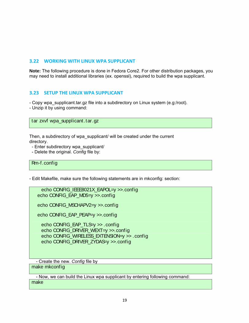
3.23 SETUP THE LINUX WPA SUPPLICANT
- Copy wpa_supplicant.tar.gz file into a subdirectory on Linux system (e.g:/root). - Unzip it by using command: tar zxvf wpa_supplicant.tar.gz
Then, a subdirectory of wpa_supplicant/ will be created under the current directory. - Enter subdirectory wpa_supplicant/ - Delete the original. Config file by:
Rm-f.config
- Edit Makefile, make sure the following statements are in mkconfig: section:
echo CONFIG_IEEE8021X_EAPOL=y >>.config echo CONFIG_EAP_MD5=y >>.config
echo CONFIG_MSCHAPV2=y >>.config
echo CONFIG_EAP_PEAP=y >>.config
echo CONFIG_EAP_TLS=y >> .config echo CONFIG_DRIVER_WEXT=y >>.config echo CONFIG_WIRELESS_EXTENSION=y >> .config
echo CONFIG_DRIVER_ZYDAS=y >>.config
- Create the new. Config file by make mkconfig
- Now, we can build the Linux wpa supplicant by entering following command: make
19
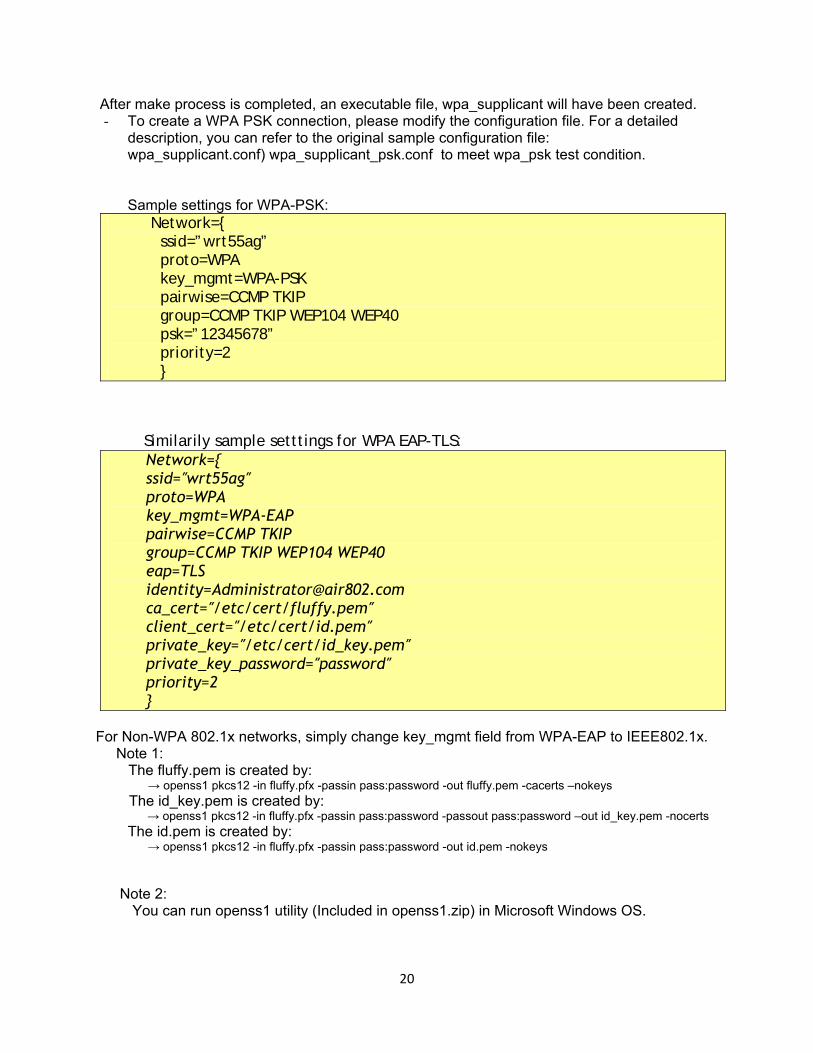
After make process is completed, an executable file, wpa_supplicant will have been created. - To create a WPA PSK connection, please modify the configuration file. For a detailed
description, you can refer to the original sample configuration file: wpa_supplicant.conf) wpa_supplicant_psk.conf to meet wpa_psk test condition. Sample settings for WPA-PSK:
Network={ ssid=”wrt55ag” proto=WPA key_mgmt=WPA-PSK pairwise=CCMP TKIP group=CCMP TKIP WEP104 WEP40 psk=”12345678” priority=2 }
Similarily sample setttings for WPA EAP-TLS: Network={ ssid=″wrt55ag″ proto=WPA key_mgmt=WPA-EAP pairwise=CCMP TKIP group=CCMP TKIP WEP104 WEP40 eap=TLS [email protected] ca_cert=″/etc/cert/fluffy.pem″ client_cert=″/etc/cert/id.pem″ private_key=″/etc/cert/id_key.pem″ private_key_password=″password″ priority=2 }
For Non-WPA 802.1x networks, simply change key_mgmt field from WPA-EAP to IEEE802.1x. Note 1: The fluffy.pem is created by: → openss1 pkcs12 -in fluffy.pfx -passin pass:password -out fluffy.pem -cacerts –nokeys The id_key.pem is created by: → openss1 pkcs12 -in fluffy.pfx -passin pass:password -passout pass:password –out id_key.pem -nocerts
The id.pem is created by: → openss1 pkcs12 -in fluffy.pfx -passin pass:password -out id.pem -nokeys
Note 2: You can run openss1 utility (Included in openss1.zip) in Microsoft Windows OS.
20
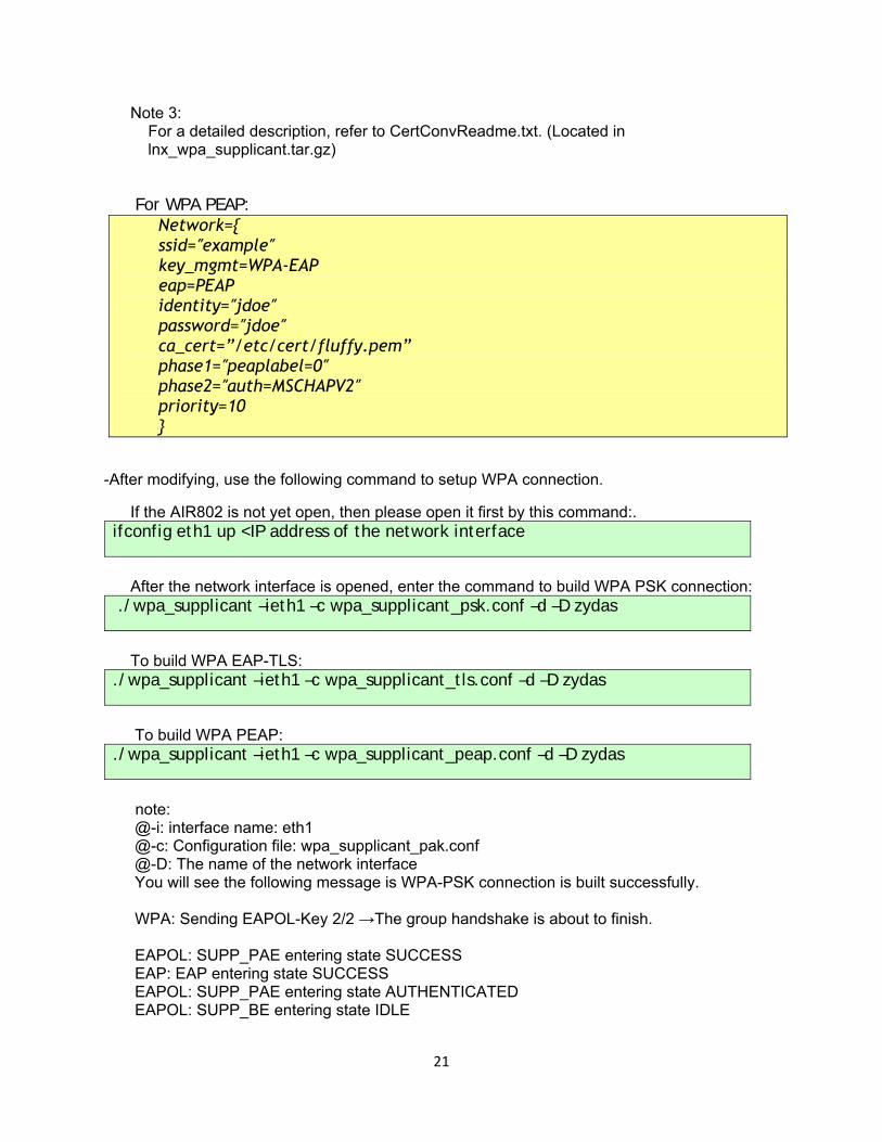
Note 3: For a detailed description, refer to CertConvReadme.txt. (Located in lnx_wpa_supplicant.tar.gz) For WPA PEAP:
Network={ ssid=″example″ key_mgmt=WPA-EAP eap=PEAP identity=″jdoe″ password=″jdoe″ ca_cert=”/etc/cert/fluffy.pem” phase1=″peaplabel=0″ phase2=″auth=MSCHAPV2″ priority=10 }
-After modifying, use the following command to setup WPA connection.
If the AIR802 is not yet open, then please open it first by this command:. ifconfig eth1 up <IP address of the network interface
After the network interface is opened, enter the command to build WPA PSK connection: ./wpa_supplicant –ieth1 –c wpa_supplicant_psk.conf –d –D zydas
To build WPA EAP-TLS: ./wpa_supplicant –ieth1 –c wpa_supplicant_tls.conf –d –D zydas
To build WPA PEAP: ./wpa_supplicant –ieth1 –c wpa_supplicant_peap.conf –d –D zydas
note: @-i: interface name: eth1 @-c: Configuration file: wpa_supplicant_pak.conf @-D: The name of the network interface You will see the following message is WPA-PSK connection is built successfully. WPA: Sending EAPOL-Key 2/2 →The group handshake is about to finish. EAPOL: SUPP_PAE entering state SUCCESS EAP: EAP entering state SUCCESS EAPOL: SUPP_PAE entering state AUTHENTICATED EAPOL: SUPP_BE entering state IDLE
21
Note of WPA supplicant operation issue: The WPA supplicant should be kept running during operation. If you press Ctrl-C to stop the WPA supplicant, it will also close the network interface card by “zd1205_close” call back routine. In this case, you will have to issue ifconfig ethx up again before using the network interface card.
3.24 CUSTOMIZATION OF VID/PID TABLE
You may desire to drive any NIC via the AIR802 USB adapter with the Zydas chipset. However, if the VID/PID isn’t listed in the driver, the linux kernel won’t load the AIR802 driver to serve the device. You can add the device’s VID/PID to the driver source. Then, the kernel will load the driver next time you plug in the USB device.
In the source file, src/zdusb.c, A static structure, AIR802_ids, stores the VID/PID list of supported products. You can add your devices VID/PID here. Then, remake, install the driver and plug in the USB adapter. You will then see it in working mode.
3.25 SPECIAL MODE FOR EMBEDDED STATION CHARIOT TEST
In an embedded system, mostly, there is no NetIQ chariot endpoint, for Wi-Fi testing, to test performance. With this mode, we can bridge the Ethernet and WLAN. The PC behind the Ethernet runs endpoint and testing data goes through the station’s wireless interface to measure the performance.
The mechanism is to specify the MAC address for association with the AP. Generally, we associate with the AP using the station’s MAC address. If we bridge the wired and wireless interfaces, data from the wired interface will be dropped by the AP. This is because the PC’s MAC address is contained in the source address of the data frames. The AP drops the frames because the source address is not in the associated station’s list. If we can use the AP’s address for association, we can run chariot on the PC to test station wireless interface performance. This is exactly like what is done in AP mode.
Someone may say, “Can’t I just set the station’s MAC as PC’s via ifconfig ethX hw ether?” Yes, perhaps you could. But most bridges will drop the data when the source address is identical to its interfaces. Therefore, we must let the address for association and address of the station be different.
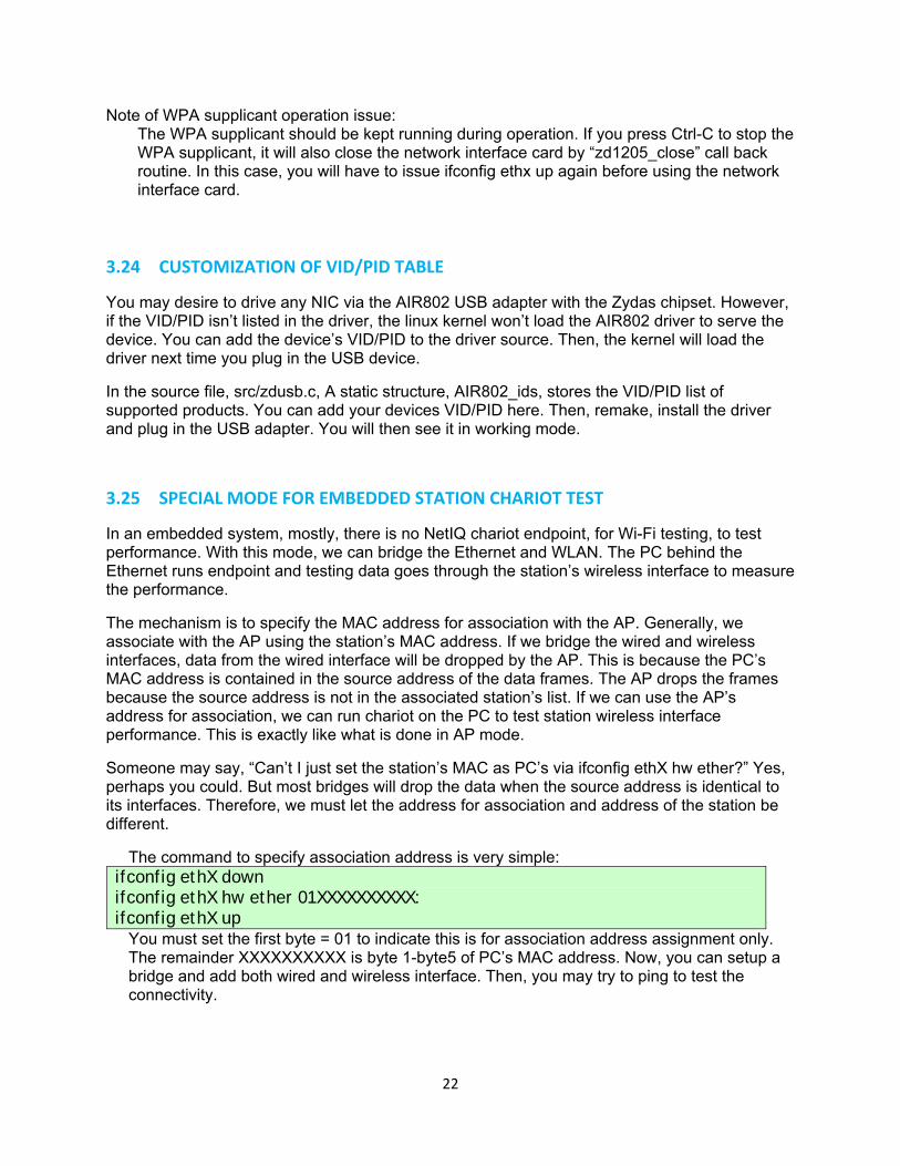
The command to specify association address is very simple: ifconfig ethX down ifconfig ethX hw ether 01XXXXXXXXXX: ifconfig ethX up
You must set the first byte = 01 to indicate this is for association address assignment only. The remainder XXXXXXXXXX is byte 1-byte5 of PC’s MAC address. Now, you can setup a bridge and add both wired and wireless interface. Then, you may try to ping to test the connectivity.
22
3.26 ZyDAS TURBO MODE
This chapter describes how to enhance the performance by enabling the AIR802 turbo mode. Turbo mode is a composition of Burst Mode and Large Packet Mode.
You may be aware that the so-called “Turbo Mode” always has compatibility problems. In order to achieve the highest performance, you need to use the AIR802 adapter with the ZyDAS chipset in both AP and Station mode. The Turbo mode is available on the AIR802 USB-ADG-2 adapter with the Linux driver only at this time. Currently, AIR802 supports it in Infrastructure Mode only. You could enable both to achieve maximum performance.
3.27 ENABLE BURST MODE
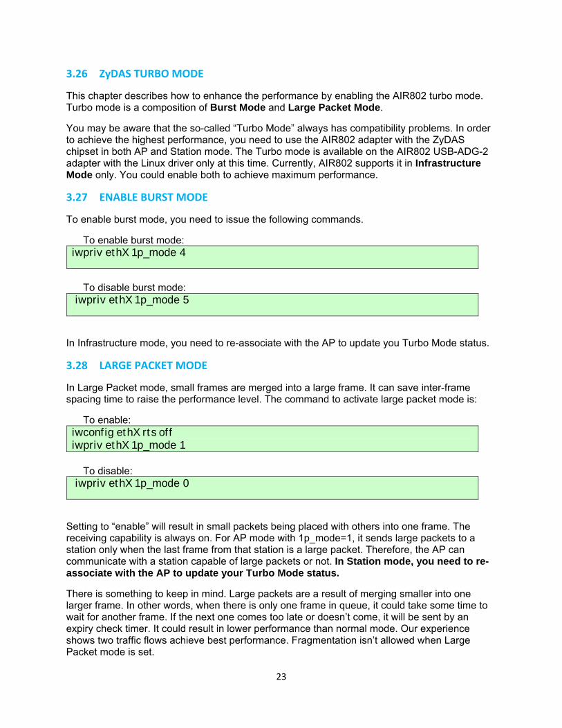
To enable burst mode, you need to issue the following commands.
To enable burst mode: iwpriv ethX 1p_mode 4
To disable burst mode: iwpriv ethX 1p_mode 5
In Infrastructure mode, you need to re-associate with the AP to update you Turbo Mode status.
3.28 LARGE PACKET MODE
In Large Packet mode, small frames are merged into a large frame. It can save inter-frame spacing time to raise the performance level. The command to activate large packet mode is:
To enable: iwconfig ethX rts off iwpriv ethX 1p_mode 1
To disable: iwpriv ethX 1p_mode 0
Setting to “enable” will result in small packets being placed with others into one frame. The receiving capability is always on. For AP mode with 1p_mode=1, it sends large packets to a station only when the last frame from that station is a large packet. Therefore, the AP can communicate with a station capable of large packets or not. In Station mode, you need to re-associate with the AP to update your Turbo Mode status.
There is something to keep in mind. Large packets are a result of merging smaller into one larger frame. In other words, when there is only one frame in queue, it could take some time to wait for another frame. If the next one comes too late or doesn’t come, it will be sent by an expiry check timer. It could result in lower performance than normal mode. Our experience shows two traffic flows achieve best performance. Fragmentation isn’t allowed when Large Packet mode is set.
23
APPENDIX A: GLOSSARY 802.11 – The Institute of Electrical and Electronic Engineers (IEEE) has created a number of wireless standards. This helps to insure that products built to comply with a specific standard are interoperable with one another even if manufactured by different companies. 802.11b – Specifies a maximum data transfer rate of 11 Mbps, an operating frequency of 2.4 GHz, and WEP encrypion for security. Commonly referred to as Wi‐Fi. 802.11g – Specifies a maximum data transfer rate of 54 Mbps, an operating frequency of 2.4 GHz and is backwards compatible with 802.11b. Commonly referred to as Wi‐Fi. Access Point – An interworking device that seamlessly connnects wired and wireless networks together. Ad‐Hoc – An Ad‐Hoc wireless LAN is a group of computers, each with a WLAN card, connected as an independent wireless LAN. Ad‐Hoc wireless LAN is applicable at a departmental scale for branch SOHO operation. BSS – Basic Service Set is an 802.11 interworking framework that includes an Access Point. Computers in a BSS must be configured with the same BSSID. CTS (Clear to Send) – An RS‐232 signal sent from the receiving station to the transmitting station that indicates is is ready to accept data. Client – A workstation or PC on a network. Default Gateway – The IP Address of either the nearest router or server for the LAN. DHCP – Dynamic Host Configuration Protocol is a method in which IP addresses are assigned from a pool of IP addresses by a server dynamically to clients on the network. DHCP is used for Dynamic IP Addressing and requires a dedicated DHCP server on the network. DNS – Domain Name System is used to map readable machine names (Internet domain names) into IP addresses. DSSS – Direct Sequence Spread Spectrum is a method the wireless cards use to transmit data over the frequency spectrum. The other method is frequency hopping. Direct sequence spreads the data over one frequency range (channel) while frequency hopping jumps from one narrow frequency band to another many times per second.
24

Dynamic IP Adress – An IP address that is automatically assigned to a client station in a TCP/IP network, generally by a DHCP server. Network devices that serve multiple users, such as servers and printers, are usually assigned static IP addresses. ESS – Extended Service Set is a set of two or more BSSs (multiple access points) that form a single network. Firmware – Programming code that is written onto read‐only memory (ROM) or programmable read‐only memory (PROM). Once written into memory, it is retained even after the device is turned off. IEEE – Institute of Electrical and Electronics Engineers is a professional society that promotes the development of standards. Infrastructure Network – One or more computers or other devices, each with a wireless adapter, connected to an Access Point. An infrastructure wireless network connected to a wired network is referred to as a Basic Service Set (BSS). A set of two or more BSS in a single network is referred to as an Extended Service Set (ESS). ISM Band – Industrial, Scientific and Medical Band operates in the frequency band 2.4 and 2.48 GHz. It is the only unlicensed band approved worldwide. LAN – A group of computers and other peripheral devices connected to share resources through wired or wireless technology, within a small geographic area. Protocol – A standard set of rules for exchanging information (format, timing, sequencing, error checking, etc.) between computers or network devices. Roaming – In infrastructure mode, this refers to a computer moving out of the range of one Access Point and connecting transparently to a new Access Point. SSID – Service Set Identifier is a unique network identification name. All client devices and Access Points that share the same SSID are able to communicate with each other. Static IP Addressing – A permanent or manually assigned IP address. Once a static IP adress is assigned, a computer or network device will use the same IP address every time it reboots and logs on to the nework, unless manually changed. TKIP – Temporal Key Integrity Protocol is part of the IEEE 802.11i encryption standard for wireless LANs. TKEP is the next generation of WEP (Wired Equivalency Protocol), which is used to secure 802.11 wireless LANs. TKIP provides per‐packet key mixing, a message integrity check and a re‐keying mechanism. WEP – Wired Equivalent Privacy mechansim is based on a 64, 128 or 256 bit algorithm.
25

WPA – Wi‐Fi Protected Access was created by the Wi‐Fi Alliance as a data encryption method for 802.11 wireless LANs. WPA is an industry‐supported, pre‐standard version of 802.11i utilizing TKIP. WLAN – Wireless Local Area Network is a group of computers and associated devices that communicate with each other wirelessly.
26
APPENDIX B: SPECIFICATIONS
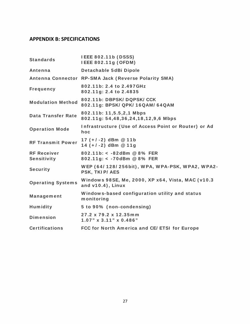
Standards IEEE 802.11b (DSSS) IEEE 802.11g (OFDM)
Antenna Detachable 5dBi Dipole
Antenna Connector RP-SMA Jack (Reverse Polarity SMA)
Frequency 802.11b: 2.4 to 2.497GHz 802.11g: 2.4 to 2.4835
Modulation Method 802.11b: DBPSK/DQPSK/CCK 802.11g: BPSK/QPK/16QAM/64QAM
Data Transfer Rate 802.11b: 11,5.5,2,1 Mbps 802.11g: 54,48,36,24,18,12,9,6 Mbps
Operation Mode Infrastructure (Use of Access Point or Router) or Ad hoc
RF Transmit Power 17 (+/-2) dBm @ 11b 14 (+/-2) dBm @ 11g
RF Receiver Sensitivity
802.11b: < -82dBm @ 8% FER 802.11g: < -70dBm @ 8% FER
Security WEP (64/128/256bit), WPA, WPA-PSK, WPA2, WPA2-PSK, TKIP/AES
Operating Systems Windows 98SE, Me, 2000, XP x64, Vista, MAC (v10.3 and v10.4), Linux
Management Windows-based configuration utility and status monitoring
Humidity 5 to 90% (non-condensing)
Dimension 27.2 x 79.2 x 12.35mm 1.07” x 3.11” x 0.486”
Certifications FCC for North America and CE/ETSI for Europe
27

APPENDIX C: WARRANTY INFORMATION BE SURE TO HAVE YOUR PROOF OF PURCHASE AND A BARCODE FROM THE PRODUCT’S PACKAGING PRIOR TO CALLING. RETURN REQUESTS CANNOT BE PROCESSED WITHOUT PROOF OF PURCHASE. IN NO EVENT SHALL AIR802’S LIABILITY EXCEED THE PRICE PAID FOR THE PRODUCT FROM DIRECT, INDIRECT, SPECIAL, INCIDENTAL, OR CONSEQUENTIAL DAMAGES RESULTING FROM THE USE OF THE PRODUCT, ITS ACCOMPANYING SOFTWARE, OR ITS DOCUMENTATION. AIR802 DOES NOT OFFER ANY REFUNDS FOR THE USB‐ADG‐2 PRODUCT UNLESS IT WAS PURCHASED VIA THE AIR8O2 ONLINE STORE AND THEN THE STORE POLICIES SHALL APPLY. AIR802 PAYS FOR GROUND SERVICES ONLY. ALL CUSTOMERS LOCATED OUTSIDE OF THE UNITED STATES OF AMERICA AND CANADA SHALL BE HELD RESPONSIBLE FOR SHIPPING AND HANDLING CHARGES. APPENDIX D: CONTACT INFORMATION AIR802 LLC Suite 137‐319 931 West 75th Street Naperville, IL 60565 USA GENERAL INQUIRIES Monday through Friday 8:30am‐5:30pm CST Tel: 630‐428‐3108 Fax: 630‐428‐1575 Email: [email protected] TECHNICAL SUPPORT For technical support, visit www.AIR802.com and click on Support to view your options.
28
29