Embed Size (px)
Citation preview

TG-F771-8E SEP. 2003K
O-180/780 Series
GENERAL
O Series ORIFLO METER is a By-pass Orifice type flowmeter.
Small sized variable flowmeter is installed onto measuring tube part
in which an orifice plate for by-pass flow is integrated.
Three different process connections,i.e., "SCREW", "FLANGE" and
"WAFER", are available for Selection.
An isolation valve is available between measuring tube and indica-
tor for indicator maintenance work even during process operation.
This eliminates the necessity of by-pass piping for maintenance pur-
pose and saves total piping cost.
In addition to standard material of STEEL version, Stainless steel
and PVC versions to cover corrosive fluids are available.
Alarm contacts are available as option. (O-780 Series)
See quick delivery model details on page 7.
FEATURES
❏ LOW COST / HIGH PERFORMANCE
Thanks to unique orifice by-pass system, total instrumentation
cost can be saved especially for medium and large sized piping
measurement.
❏ COMPACT DESIGN
Small sized indicator saves space in plants.
❏ EASY INSTALLATION
"SCREW", "FLANGE" and "WAFER" are ready to meet field re-
quirements.
By-pass piping for maintenance purpose can be skipped by using
isolation valve.
❏ FOR ALL FLOW DIRECTIONS
BOTTOM TO TOP, TOP TO BOTTOM, LEFT TO RIGHT, RIGHT
TO LEFT.
ORIFLO is applicable for all possible flow directions. Change of
such flow direction is possible in field even after installation.
❏ ALARM CONTACT
Besides local flow rate indication, alarm contact (s) are available.
ORIFLO can be used as FLOWSWITCH.
❏ EASY MAINTENANCE
Simple design and limited number of parts saves maintenance
work.
❏ HIGH ANTI CORROSIVE CAPABILITY VERSION
Stainless steel and PVC versions are available for corrosive fluid
application.
COST EFECTIVE FLOW MEASUREMENT FORLIQUIDS AND GASES
ORIFLO METER
MAIN APPLICATIONS
❏ Hot and cool water as well as air flow measurement at Air condi-
tioning
❏ Medium and large line measurement at General process
❏ Cooling water lines
❏ Water treatment process
❏ Pure and Ultra pure water production facilities process
❏ Testing of Fire fighting pumps
❏ Testing of blowers
❏ Others

O-180/780 ORIFLO METER
TG-F771-8E2 TOKYO KEISO CO., LTD.
Measuring tube
Processpiping
Orifice plate
By-pass return
ValveHandle
Return tube
By-pass piping
Isolation valve
Metering tube(Graduated)
Float
Strainer
By-pass orifice
As shown in the figure, differential pressure is produced across the
Main orifice plate by flow velocity which corresponds to flow rate.
A small sized flowmeter (Variable area flowmeter) is mounted onto
this differential pressure production unit. By this arrangement, the
flow rate through the flowmeter corresponds to the flow rate through
the Process piping.
Thus, scale range for Process piping can be engraved onto the small
sized flowmeter and the flow rate through the Process piping is indi-
cated by the position of float of the flowmeter.
Normally, an isolation valve is provided between the measuring tube
and the indicator for the purpose of indicator maintenance with no in-
terference of process operation. (This valve is for maintenance/ iso-
lation purpose and not for flow control purpose.)
A magnet piece is buried into the float for Alarm version which at-
tracts reed switch for alarm contact output. The setting point of alarm
is adjustable by shifting the location of reed switch.
a. Indicatorassembly
c. Measuringtube
b. Isolationvalve
OPERATION PRINCIPLE
CONSTRUCTION
ORIFLO consists of : a. lndicator
b. lsolation valve
c. Measuring tube
The figure is an extended view of metallic material version.
(It would differ in case of PVC version.)

O-180/780 ORIFLO METER
TG-F771-8E TOKYO KEISO CO., LTD. 3
MATERIAL CONSTRUCTION
Different materials are available for measuring tube, isolation valve, indicator and sealings to cover various fluids
as per the following table ;
MODEL CODE
0 –
1678
– – –
SFW
NCB
– – – – –
– –
00000
45
11223
50
05052
00
– – – – –
12345
NFEZ
MODE CODE
FUNCTION *1
FLOW DIRECTION
PROCESS CONNECTION
ISOLATION VALVE *2
LINE SIZE
MATERIAL CODE
SEAL MATERIAL
DESCRIPTION
LOCAL INDICATION ONLYLOCAL INDICATION + ALARM CONTACTLOCAL INDICATION + OPITICAL ALARM UNIT (OLD MODEL O-76 )BOTTOM➝TOPLEFT➝RIGHTRIGHT➝LEFTTOP➝BOTTOMSCREW CONNECTIONFLANGE CONNECTIONWAFER CONNECTIONNOT PROVIDEDPROVIDEDINDICATOR SEPARATION VERSION10mm15mm20mm25mm32mm
450mm500mmMATERIAL CLASS 1 (Steel)MATERIAL CLASS 2 (SUS304)MATERIAL CLASS 3 (SUS316)MATERIAL CLASS 4 (PVC)MATERIAL CLASS 5 (HT.PVC)NBRFPMEPDMSPECIAL
– – –187868
~ ~
*1: O-190 Dial indication version available. Refer to page 13 for details.*2: Ball valves are provided for indicator separation version (O- 8 - B). Refet to page 11 for details.
Measuring tube
Screw connection
Flange connection
Wafer connection
Orifice plate
Isolation valve body / shaft
Indicator body
Metering tube
FloatFor Iiquids
For Gases
Cover, scale
Sealing
Material Class 1
SCS14/FCD400 *1
SGP/SS400
SS400/SCS14 *3
SUS304
SCS14/SUS316
SCS14
Pyrex glass
SUS316
Glass
SUS304/ABSPolycarbonate
NBR
FPM
Material Class 2
SCS14
SUS304
SUS304/SCS14 *3
SUS304
SCS14/SUS316
SCS14
Pyrex glass
SUS316
Glass
SUS304/ABSPolycarbonate
NBR
FPM
Material Class 3
SCS14
SUS316
SUS316/SCS14 *3
SUS316
SCS14/SUS316
SCS14
Pyrex glass
SUS316
Glass
SUS304/ABSPolycarbonate
NBR
FPM
Material Class 4
PVC
PVC
PVC
PVC
PVC/PP
PVC
Pyrex glass *2
PVC
Glass
Polycarbonate
NBR
FPM
Material Class 5
HT.PVC
HT.PVC
HT.PVC
HT.PVC
HT.PVC/PP
HT.PVC
Pyrex glass
HT.PVC
Glass
Polycarbonate
NBR
FPM
Part description
*1: SCS14 for 10mm~25mm*2: PVC (Max. Press. 0.6MPa) and Acryl (Max. Press. 0.4MPa, Max. Temp. 40°C) tapered tubes are also available.*3: SCS14 for 25mm, 40mm~150mm (JIS10K)
Abbriviation of material PP : Polypropylene NBR : Nitrile Butadiene Rubber FPM : Fluoro rubber HT.PVC : High temp. PVC ABS : Acrylonitrile Butadiene Styrene
O-180/780 ORIFLO METER
TG-F771-8E4 TOKYO KEISO CO., LTD.
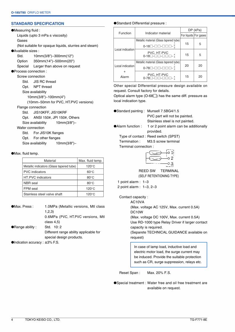
STANDARD SPECIFICATION
●Measuring fluid : Liquids (upto 3 mPa.s viscosity) Gases (Not suitable for opaque liquids, slurries and steam)
●Available sizes : Std. 10mm(3/8")~300mm(12") Option 350mm(14")~500mm(20") Special Larger than above on request●Process connection : Screw connection
Std. JIS RC threadOpt. NPT threadSize availability 10mm(3/8")~100mm(4") (10mm~50mm for PVC, HT.PVC versions)
Flange connection
Std. JIS10KFF, JIS10KRFOpt. ANSI 150#, JPI 150#, OthersSize availability 10mm(3/8")~
Wafer connectionStd. For JIS10K flangesOpt. For other flanges
Size availability 10mm(3/8")~
●Max. fluid temp.
Material
Metallic indicators (Glass tapered tube)
PVC indicators
HT.PVC indicators
NBR seal
FPM seal
Stainless steel valve shaft
Max. fluid temp.
120°C
60°C
80°C
80°C
120°C
120°C
●Max. Press : 1.0MPa (Metallic versions, Mtl class1,2,3)
0.6MPa (PVC, HT.PVC versions, Mtlclass 4,5)
●Range ability : Std. 10: 2Different range ability applicable forspecial design products.
●Indication accuracy : ±3% F.S.
●Standard Differential pressure :
Other special Differential pressure design available onrequest. Consult factory for details.Optical alarm type (O-68�) has the same diff. pressure aslocal indication type.
●Standard painting : Munsell 7.5BG4/1.5PVC part will not be painted.Stainless steel is not painted.
●Alarm function : 1 or 2 point alarm can be additionallyprovided.
Type of contact : Reed switch (SPST)Termination : M3.5 screw terminalTerminal connection :
1 point alarm : 1–32 point alarm : 1–3, 2–3
Contact capacity :AC10VA(Max. voltage AC 125V, Max. current 0.5A)DC10W(Max. voltage DC 100V, Max. current 0.5A)Use RD-1000 type Relay Driver if larger contactcapacity is required.(Separete TECHNICAL GUIDANCE available onrequest)
Reset Span : Max. 20% F.S.
●Special treatment : Water free and oil free treatment areavailable on request.
Function
Local indication
Local indication
Alarm
+
Indicator materialDP (kPa)
For liquids For gases
Metallic material (Glass tapered tube)
Metallic material (Glass tapered tube)
PVC, HT.PVC
PVC, HT.PVC
15
15
15
20 20
20
5
5
REED SW TERMINAL(SELF RETENTIONING TYPE)
In case of lamp load, inductive load andelectric motor load, the surge current maybe induced. Provide the suitable protectionsuch as CR, surge suppression, relays etc.

O-180/780 ORIFLO METER
TG-F771-8E TOKYO KEISO CO., LTD. 5
Consult factory for other scale ranges, if required.
The calculation of figures in the above flow range table hasbeen made on the premises that SGP, a JIS code name fora carbon steel pipe for ordinary piping, had been used formain pipes. ln case of pipes other than SGP, multiply theabove liquid quantity by (the inner diameter of a pipe used ÷the inner diameter of a SGP pipe)2.
SCALE RANGE
●FOR LIQUID MEASUREMENT
Float material
Stainless steel (Local indicator)
Stainless steel (With alarm)
PVC (All types)
Density of float
7.9g/cm3
7.3g/cm3
3.0g/cm3
Qw = Q ×γo (γ f – 1)
(γ f – γo)
DP 50kPa *3 0.3 ~ 1 0.4 ~ 2 0.65 ~ 5 0.9 ~ 8.5 1.5 ~ 14 2.5 ~ 20 4 ~ 30 8 ~ 50 10 ~ 70 15 ~ 120 30 ~ 180 40 ~ 250 80 ~ 450 100 ~ 700 140 ~ 1000 180 ~ 1300 250 ~ 1600 350 ~ 2200 700 ~ 2600
DP 15kPa *2 0.15 ~ 0.6 0.2 ~ 1.2 0.35 ~ 2.5 0.5 ~ 4.5 0.8 ~ 8 1.2 ~ 10 2 ~ 15 4 ~ 25 5 ~ 40 8 ~ 70 15 ~ 100 20 ~ 150 40 ~ 250 60 ~ 400 80 ~ 550 100 ~ 700 150 ~ 900 200 ~ 1200 400 ~ 1500
3/8B1/2B3/4B1B
11/4B11/2B
2B21/2B
3B4B5B6B8B10B12B14B16B18B20B
10mm15mm20mm25mm32mm40mm50mm65mm80mm100mm125mm150mm200mm250mm300mm350mm400mm450mm500mm
FULL SCALE RANGE m3/h (Water, Density 1.0g/cm3, 1.0mPa·s viscosity) DP 10kPa *1 0.14 ~ 0.5 0.18 ~ 1 0.3 ~ 2.4 0.45 ~ 4 0.7 ~ 6.5 1 ~ 9 1.8 ~ 12 3.5 ~ 20 4.2 ~ 32 7 ~ 55 12 ~ 80 16 ~ 120 35 ~ 200 50 ~ 300 65 ~ 450 85 ~ 550 120 ~ 700 160 ~ 950 350 ~ 1200
SIZE
*1: Range ability 10 : 2.5*2: Range ability 10 : 2*3: Range ability 10 : 2 (10 : 1.5 on request)
Inner diameter[mm]12.716.121.627.635.741.652.967.980.7
105.3130.8155.2204.7254.2304.7
SIZE10mm15mm20mm25mm32mm40mm50mm65mm80mm100mm125mm150mm200mm250mm300mm
Inner diameter of a SGP pipe
Qw : Water converted range
Q : Flow range for actual liquid
: Density of actual Liquid
: Density of float
γo
γ f
From the above table, select the connection size (100mm, 125mmetc.) in which 44.1m3/h is included.
Qw = 50 × 0.8 � (7.9 – 1)(7.9 – 0.8)
= 44.1 (m3/h)
Example: The flow rate converted to water, of alcohol 50m3/h (Density: 0.8g/cm3) can be calculated as follows. Theflowmeter to be used is to be stainless (local indication only).
Above table is indicated based on water flow measurement(Density 1.0g/cm3 Viscosity 1.0mPa.s). When the fluidSpecific gravity is other than 1.0, conduct conversioncalculation by the following formula, and refer to the table :
O-180/780 ORIFLO METER
TG-F771-8E6 TOKYO KEISO CO., LTD.
SIZE
10mm15mm20mm25mm32mm40mm50mm65mm80mm
100mm125mm150mm200mm250mm300mm 350mm400mm450mm500mm
3/8B1/2B3/4B1B
1 1/4B1 1/2B
2B2 1/2B
3B4B5B6B8B10B12B 14B16B18B20B
DP 5kPa *1~~~~~~~~~~~~~~~~~~~
FULL SCALE RANGE m3/h (nor) (Air, 0°C, 1 atm)DP 10kPa *2
~~~~~~~~~~~~~~~~~~~
2.33.25812162545601001502103805509001100150018002200
9 204575
120170280460640
11001650230041006400900011000150001900023000
3.54.57.5111822356585
140220300500800
12001600210026003200
122865
100150240350600850
15002300330055008500
1200015000200002600033000
4.56
101525325090
120200300400750
110017002200280035004200
183885
140240320500850
12002000320045007500
120001700021000280003600045000
DP 20kPa *2~~~~~~~~~~~~~~~~~~~
*1: Range ability 10 : 2*2: Range ability 10 : 2 (10 : 1.5 on request)
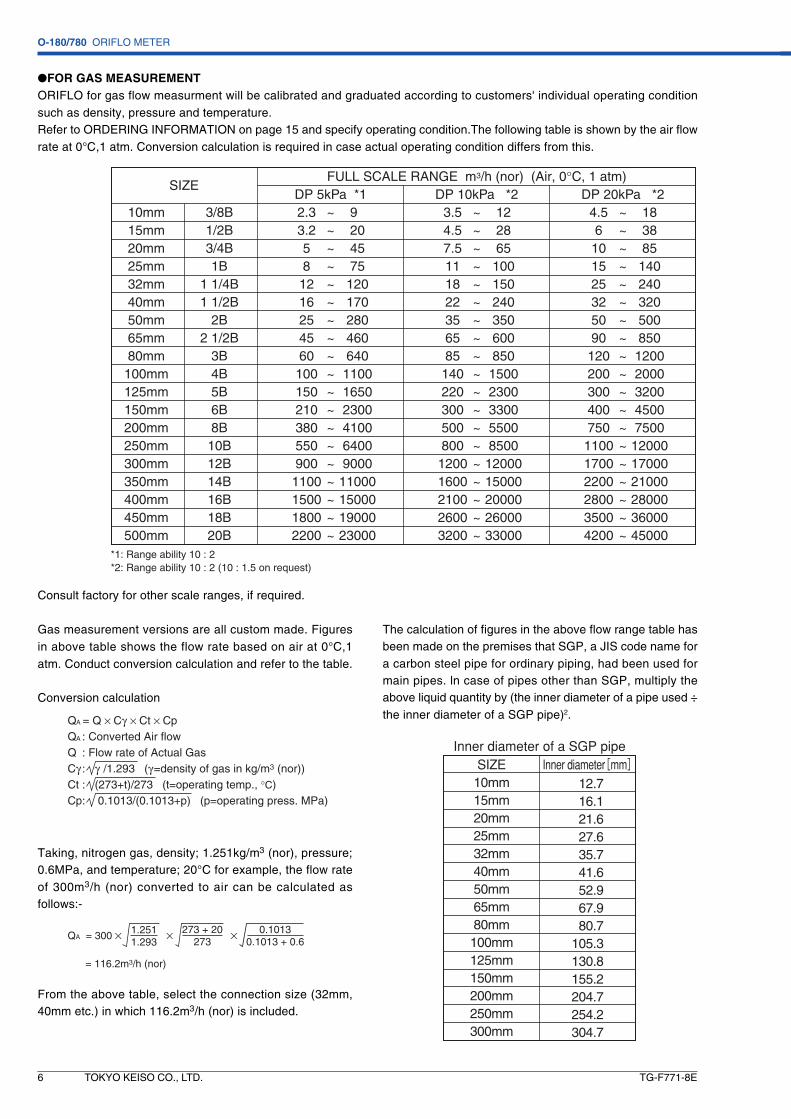
Consult factory for other scale ranges, if required.
Gas measurement versions are all custom made. Figuresin above table shows the flow rate based on air at 0°C,1atm. Conduct conversion calculation and refer to the table.
Conversion calculation
The calculation of figures in the above flow range table hasbeen made on the premises that SGP, a JIS code name fora carbon steel pipe for ordinary piping, had been used formain pipes. ln case of pipes other than SGP, multiply theabove liquid quantity by (the inner diameter of a pipe used ÷the inner diameter of a SGP pipe)2.
●FOR GAS MEASUREMENTORIFLO for gas flow measurment will be calibrated and graduated according to customers' individual operating conditionsuch as density, pressure and temperature.Refer to ORDERING INFORMATION on page 15 and specify operating condition.The following table is shown by the air flowrate at 0°C,1 atm. Conversion calculation is required in case actual operating condition differs from this.
Q = Q × Cγ × Ct × CpQ : Converted Air flowQ : Flow rate of Actual GasCγ : γ /1.293 (γ=density of gas in kg/m3 (nor))Ct : (273+t)/273 (t=operating temp., °C)Cp : 0.1013/(0.1013+p) (p=operating press. MPa)
A
A
Taking, nitrogen gas, density; 1.251kg/m3 (nor), pressure;0.6MPa, and temperature; 20°C for example, the flow rateof 300m3/h (nor) converted to air can be calculated asfollows:-
QA = 300 × × ×1.2511.293
= 116.2m3/h (nor)
273 + 20273
0.10130.1013 + 0.6
From the above table, select the connection size (32mm,40mm etc.) in which 116.2m3/h (nor) is included.
Inner diameter[mm]12.716.121.627.635.741.652.967.980.7
105.3130.8155.2204.7254.2304.7
SIZE10mm15mm20mm25mm32mm40mm50mm65mm80mm100mm125mm150mm200mm250mm300mm
Inner diameter of a SGP pipe

O-180/780 ORIFLO METER
TG-F771-8E TOKYO KEISO CO., LTD. 7
-10 -12 -15 -20 -25 -30 -35 -40 -45 -50 -55 -60 -65 -70 -75 -80 -85 -90 -95
(0.5) (0.5) (0.5) (0.5) (1.0) (1.0) (1.0) (1.0) (1.0) (2.0) (2.0) (2.0) (2.0) (2.0) (5.0) (5.0) (5.0) (5.0) (5.0)
10
8
6
4
2
12
9
6
32.4
15
10
5
3
20
15
10
54
40
30
20
108
45
40
30
20
109
25
20
15
10
5
50
40
30
20
10
30
20
10
6
35
30
20
10
7
55
50
40
30
20
11
60
50
40
30
20
12
65
60
50
40
30
20
13
70
50
30
14
90
70
50
30
18
9590
70
50
30
19
7570
50
30
15
80
60
40
1017
8580
60
40
2017
Series for quick delivery O-180-��-���-2F
Appoint “model code” when ordering. Parts such as indicator, isolation valve and measuring tube shall be delivered disas-
sembled. Put them together in accordance with the required flow direction.
●SPECIFICATIONLIQUID : WaterDENSITY : 1.0g/cm3
VISCOSITY : 1.0mPa·sMAX. PRESSURE : 15kPa (Screw connection)
20kPa (Wafer connection)
WAFER CONNECTION (JIS-10K)–––
O-180-WC-025-2F–
O-180-WC-040-2FO-180-WC-050-2FO-180-WC-065-2FO-180-WC-080-2FO-180-WC-100-2F
0.1 ~ 0.50.2 ~ 10.5 ~ 2.5 1 ~ 51.6 ~ 8 2 ~ 103.6 ~ 18 6 ~ 30 8 ~ 40 14 ~ 70
m3/hm3/hm3/hm3/hm3/hm3/hm3/hm3/hm3/hm3/h
SIZE
10mm15mm20mm25mm32mm40mm50mm65mm80mm100mm
SCREW CONNECTION (Rc)O-180-SC-010-2FO-180-SC-015-2FO-180-SC-020-2FO-180-SC-025-2FO-180-SC-032-2FO-180-SC-040-2FO-180-SC-050-2FO-180-SC-065-2FO-180-SC-080-2FO-180-SC-100-2F
MODEL CODEFLOW RANGE
●Standard scale graduationStandard scale division is set as per following figure. Select it from F.S. value asbelow when setting.
●Packing method when deliveredThe 3 parts of indicator, isolation valve,
and measuring tube are packed as perpicture. (It can be assembled at factoryif desired. Advise us of required flow di-rection.)
The figures in ( ) shows minimum graduation of scale. These figuresmay change according to the differential pressure.

O-180/780 ORIFLO METER
TG-F771-8E8 TOKYO KEISO CO., LTD.
Mass (kg)1.51.61.71.82.02.1 2.6
*(A)104106108112120123131
L
70
748590
Main pipe SCS14Mass (kg)
2.02.22.33.03.55.0
*(A)
120123131140149162
L
748590100110120
SIZE
10mm15mm20mm25mm32mm40mm50mm65mm80mm100mm
Main pipe FCD400
––ー
––ー
––ー
* A is reduced by 40mm in case lsolation valve is not provided. Mass of Isolation valve is 0.4kg
* A is reduced by 40mm in case lsolation valve is not provided. Mass of Isolation valve is 0.4kg
Mass (kg)
4.0
4.3
7.5
*(A)
176
183
198
L
120
160
SIZE
65mm
80mm
100mm
* A is reduced by 44mm in case lsolation valve is not provided. Mass of Isolation valve is 0.2kg
Mass (kg)
1.1
1.1
1.1
1.1
1.2
1.2
1.2
*(A)
146
146
146
146
153
158
163
L
75
85
90
SIZE
10mm
15mm
20mm
25mm
32mm
40mm
50mm
1 MATERIAL CLASS 1
●SCREW CONNECTION TYPE O-18 -SC- -
(FCD400) 32mm~100mm, (SCS14) 10mm~50mm
2 MATERIAL CLASS 2,3 (SCS14) 65mm~100mm
EXTERNAL DIMENSION
3 MATERIAL CLASS 4,5 (PVC, HT.PVC) 10mm~50mm

O-180/780 ORIFLO METER
TG-F771-8E TOKYO KEISO CO., LTD. 9
*1: A is reduced by 40mm in case Isolation valve is not provided.*2: In case flange rating JIS10K Mass of Isolation valve is 0.4kg
*2 Mass (kg)
3.2 3.6 4.2 5.4 6.7 7.1 8.5 11.4 12
15.5 20 27 35 50 61 74 93 115 130
*1(A)142 144 147 150 154 157 163 171 178 190 203 216 241 267 292 311 336 362 387
L
540
SIZE
10mm15mm20mm25mm32mm40mm50mm65mm80mm
100mm125mm150mm200mm250mm300mm350mm400mm450mm500mm
Main pipe 1 , 2 , 3(SGP, SUS304, SUS316)MATERIAL CLASS 1, 2, 3 (SGP, SUS304, SUS316)
●FLANGE CONNECTION TYPE O-18 -FC- -
MATERIAL CLASS 4, 5 (PVC, HT.PVC)
Special design with L dimension of 200mm (10mm~80mm) and 300mm (100mm~500mm) available on request, Contact Tokyo Keiso for details.
*1: A is reduced by 44mm in case Isolation valve is not provided.*2: In case flange rating JIS10K Mass of Isolation valve is 0.2kg
*2 Mass (kg)
1.11.21.31.51.71.92.32.73.14.15.58.09.514.520
*1(A)127 129 131 134 137 142 148 156 162 175 208 220 246 271 297
L
540
SIZE
10mm15mm20mm25mm32mm40mm50mm65mm80mm
100mm125mm150mm200mm250mm300mm
(PVC, HT.PVC)
Main pipe 4 , 5
O-180/780 ORIFLO METER
TG-F771-8E10 TOKYO KEISO CO., LTD.
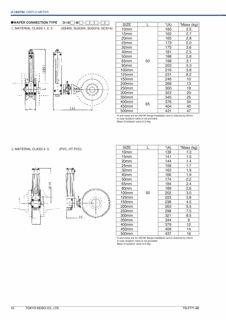
2 MATERIAL CLASS 4, 5 (PVC, HT.PVC)
1 MATERIAL CLASS 1, 2, 3 (SS400, SUS304, SUS316, SCS14)
●WAFER CONNECTION TYPE O-18 -W - -
* A and mass are for JIS10K flange installation and is reduced by 40mm in case Isolation valve is not provided. Mass of Isolation valve is 0.4kg
*Mass (kg)2.5 2.7 2.8 2.0 3.6 2.5 2.8 3.1 3.3 3.8 8.2 10 13 18 20 25 34 40 47
*(A)160 162 165 173 175 181 188 198 203 216 231 246 268 300 322 345 376 404431
L
50
65
SIZE10mm15mm20mm25mm32mm40mm50mm65mm80mm100mm125mm150mm200mm250mm300mm350mm400mm450mm500mm
* A and mass are for JIS10K flange installation and is reduced by 44mm in case Isolation valve is not provided. Mass of Isolation valve is 0.2kg
*Mass (kg)1.31.31.41.71.91.92.22.42.63.03.84.55.57.58.59121416
*(A)139 141 144 158 163 166 174 184 189 202 223 238 263 298 321 344 379 409 437
L
50
SIZE10mm15mm20mm25mm32mm40mm50mm65mm80mm100mm125mm150mm200mm250mm300mm350mm400mm450mm500mm
O-180/780 ORIFLO METER
TG-F771-8E TOKYO KEISO CO., LTD. 11
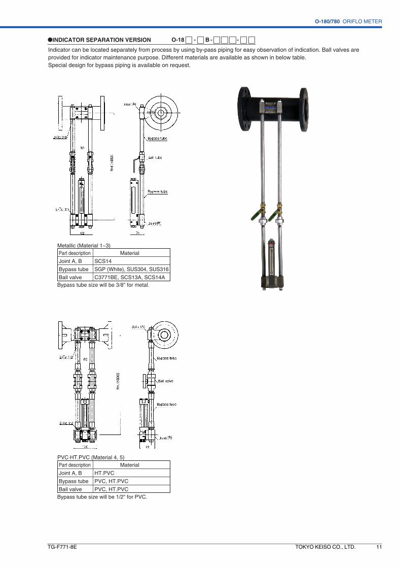
Indicator can be located separately from process by using by-pass piping for easy observation of indication. Ball valves are provided for indicator maintenance purpose. Different materials are available as shown in below table.Special design for bypass piping is available on request.
●INDICATOR SEPARATION VERSION O-18 - B - -
Part description
Joint A, B
Bypass tube
Ball valve
Material
SCS14
SGP (White), SUS304, SUS316
C3771BE, SCS13A, SCS14A
Metallic (Material 1~3)
Bypass tube size will be 3/8" for metal.
Part description
Joint A, B
Bypass tube
Ball valve
Material
HT.PVC
PVC, HT.PVC
PVC, HT.PVC
PVC·HT.PVC (Material 4, 5)
Bypass tube size will be 1/2" for PVC.

O-180/780 ORIFLO METER
TG-F771-8E12 TOKYO KEISO CO., LTD.
2 LOCAL INDICATION WITH ALARM CONTACT O-78
1 LOCAL INDICATION ONLY O-18
●ISOLATION VALVE
●INDICATOR
MATERIAL (SCS14) MATERIAL (PVC, HT.PVC)
MATERIAL (SCS14) MATERIAL (PVC, HT.PVC)
MATERIAL (SCS14) MATERIAL (PVC, HT.PVC)
85 44
5
5
OP
EN
OP
EN
57
(230
)
G1/2
48

O-180/780 ORIFLO METER
TG-F771-8E TOKYO KEISO CO., LTD. 13
In addition to standard O-180 with Glass tube flowmeter indication, O-190 series Dial indication type is available. Consultfactory for details.
A. Integrated Dial Indication type O-190-DG
O-190-DG indicaters flowrate by pressure gauges. 3 waymanifold valve is provided.
B. 0-190-B ■ separate indication seriesDifferent types of pressure indicators can be used for indication of flow rate. They can be installed separately away fromorifice piping for better observation.
O-190 SERIES DIAL INDICATOR TYPE
LRc1/4
Rc1/4
H
50
A'A
WINDOW
200
400
WINDOW
(160
0)
Air Vent Air VentZERO ADJ.(H)
(H)
(L)
(L)54Rc1/2 Rc1/2
MAX.240
MAX.87
(235
)
øD
t
2" pipe
(79)
LRc1/4
HRc1/4
270
Max
.120
500
Max.190 Max.95
(A±2
)
(90(±))
Rc1/4
a. Manometer indication
c. Dial indication d. Indication in protection housing
b. U shaped Manometer indication

O-180/780 ORIFLO METER
TG-F771-8E14 TOKYO KEISO CO., LTD.
SUGGESTIONS
Description
Flange
Bolt and nuts
Gaskets
Material
SS400, SUS304,SUS316
SS400, SUS304
Non-asbestos, NBR, FPM, Others
Q'ty
2
As required
2
Gas application Liquid application for local indicator
Alarm versions (Metallic material) Alarm versions (PVC, HT.PVC)
center
top top
top
Description
TS Socket welding flange
Bolt and nuts
Gaskets
Material
PVC, HT.PVC
SS400, SUS304
NBR, EPDM, Others
Q'ty
2
As required
2
Air elimination plug
Rc1/4
R1/4
Airelimination
Drainelimination
MATERIALCLASS 2 3
Nipple
Ball valve
ASTM A351-CF8M
(1) Upper/lower straight tube lengthIn order to make measurement in the predeterminedaccuracy, the straight run of tube is required. The requiredstraight run of tube varies, depending on the diameterratio of contraction device and the piping shape. Refer toJIS Z 8762-2: 2007.
(3) Reading of flow rateThe flow rate is to be read by the position of floatand engraved graduation. Refer to the following :
(2) Air bubble elimination and drainingAir bubble in the indicator may cause measurement error.Eliminate the air in the indicator through Air eliminationplug at the top of indicator for the start-up.
(4) Flow directionBy changing the direction of indicator, ORIFLO may beused for any flow direction of bottom to top, left to right,right to left and top to bottom. This change can beconducted in the field as well.
Ball valves are available for air eliminator and drain outas option as follows ;
MATERIAL CONSTRUCTION
(2) TS FLANGESTS socket welding flanges are also available on request :
ACCESSORIES
(1) COUNTER FLANGESCounter flanges are available on request.Supply scope is as follows :

O-180/780 ORIFLO METER
TG-F771-8E TOKYO KEISO CO., LTD. 15
Specify the following for order or inquiry ;
MODEL O – ■ 8 ■ – ■ ■ – ■■■ – ■ ■
Fluid name ______________________________________________________________Density _____________■ g/cm3 ■ kg/m3(nor) ■_____________Viscosity _____________■ mPa.s
Pressure Nor._____________Max._____________ ■ MPa ■_____________Temperature Nor._____________Max._____________ ■ °C ■_____________
Connection ■ Rc ■ Other thread (_____________)■ JIS10KFF ■ JIS10KRF ■ Other flange (_____________)■ Wafer for JIS10K flange ■ Wafer for other flange (_____________)
Inner diameter of process piping ■ SGP ■_____________mm_____________
Full scale _____________■ m3/h ■ m3/h(nor) ■_____________
Seal material ■ NBR ■ FPM ■ Others (_____________)
In case of alarm version Number of point ■ 1 ■ 2 Setting 1 ■ H ■ L at________■ m3/h ■ m3/h(nor) Setting 2 ■ H ■ L at________■ m3/h ■ m3/h(nor)
Installation accessories ■ Counter flanges Material ( )
■ TS flanges Material ( )Other special instructions, if any ; ________________________________________________________________________________________________________________________________________________ __
ORDERING INFORMATION

O-180/780 ORIFLO METER
TG-F771-8E16
Head Office : Shiba Toho Building, 1 – 7 – 24 Shibakoen, Minato-ku, Tokyo 105 – 8558
Tel : +81-3 – 3431 – 1625 (KEY) ; Fax : +81-3 – 3433 – 4922
e-mail : [email protected] ; URL : http://www.tokyokeiso.co.jp
* Specification is subject to change without notice.
FEATURES
DIGITDIGITAL FLOW AL FLOW INDICAINDICATIONTION
DIGITAL FLOW INDICATION
DIFFERENTIAL PRESSURE FLOWMETERwith
HDT 1000 SERIES ORIFLO METER
HDT 1000 Series oriflo meter works as one flowmeter by the integration of orifice and multi-digital differential pressure indicator. It indicates flow rate by measuring directly the differential pressure generated across the orifice inside pipe.
• For liquids and gases• Compact indicators save the space• Screw(up to 100mm), flange and wafer connection. From 15mm to 300mm including both are available.• Wide rangeability 10 to 100% and accuracy ±3% Full Scale.
For details see Technical Guidance of HDT 1000.
DIFFERENTIAL PRESSURE FLOWMETERwith
HDT 1000 SERIES ORIFLO METER