Embed Size (px)
Citation preview
a-278
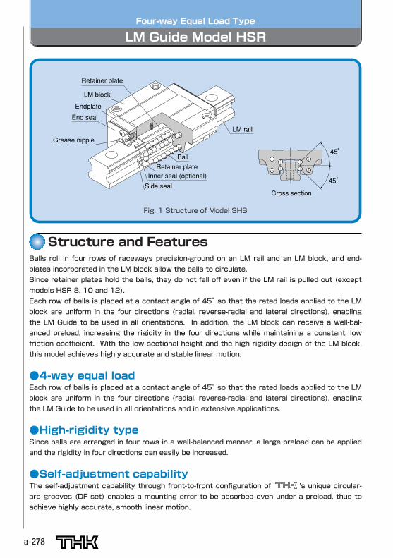
Four-way Equal Load Type
LM Guide Model HSR
Structure and Features
45°
45° Inner seal (optional)
Side seal
Retainer plate
Endplate
End seal
Retainer plate
LM block
Ball
LM rail
Grease nipple
Cross section
日本特許番号第1149638号・第1627053号・第1692316号米国特許登録・独国特許登録・仏国特許登録・英国特許登録
Balls roll in four rows of raceways precision-ground on an LM rail and an LM block, and end-
plates incorporated in the LM block allow the balls to circulate.
Since retainer plates hold the balls, they do not fall off even if the LM rail is pulled out (except
models HSR 8, 10 and 12).
Each row of balls is placed at a contact angle of 45°so that the rated loads applied to the LMblock are uniform in the four directions (radial, reverse-radial and lateral directions), enabling
the LM Guide to be used in all orientations. In addition, the LM block can receive a well-bal-
anced preload, increasing the rigidity in the four directions while maintaining a constant, low
friction coefficient. With the low sectional height and the high rigidity design of the LM block,
this model achieves highly accurate and stable linear motion.
●4-way equal loadEach row of balls is placed at a contact angle of 45°so that the rated loads applied to the LMblock are uniform in the four directions (radial, reverse-radial and lateral directions), enabling
the LM Guide to be used in all orientations and in extensive applications.
●High-rigidity typeSince balls are arranged in four rows in a well-balanced manner, a large preload can be applied
and the rigidity in four directions can easily be increased.
●Self-adjustment capabilityThe self-adjustment capability through front-to-front configuration of 's unique circular-
arc grooves (DF set) enables a mounting error to be absorbed even under a preload, thus to
achieve highly accurate, smooth linear motion.
Fig. 1 Structure of Model SHS
a. Dimensions of the LM Guides
a-279
LMGuideModelHSR
a279
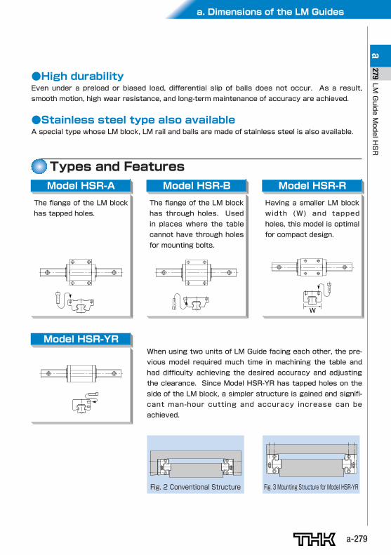
Types and FeaturesModel HSR-A Model HSR-B Model HSR-R
W
●High durabilityEven under a preload or biased load, differential slip of balls does not occur. As a result,
smooth motion, high wear resistance, and long-term maintenance of accuracy are achieved.
●Stainless steel type also availableA special type whose LM block, LM rail and balls are made of stainless steel is also available.
The flange of the LM block
has tapped holes.
Model HSR-YR
The flange of the LM block
has through holes. Used
in places where the table
cannot have through holes
for mounting bolts.
Having a smaller LM block
width (W) and tapped
holes, this model is optimal
for compact design.
When using two units of LM Guide facing each other, the pre-
vious model required much time in machining the table and
had difficulty achieving the desired accuracy and adjusting
the clearance. Since Model HSR-YR has tapped holes on the
side of the LM block, a simpler structure is gained and signifi-
cant man-hour cutting and accuracy increase can be
achieved.
Fig. 2 Conventional Structure Fig. 3 Mounting Structure for Model HSR-YR
a-280
Model HSR-CA Model HSR-CB
Model HSR-HA Model HSR-HB Models HSR100/120/150 HA/HB/HR
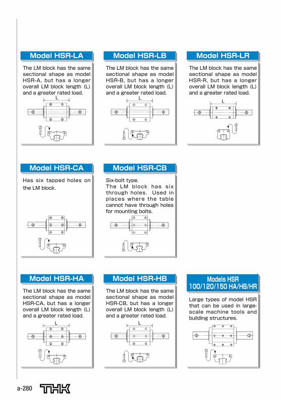
Model HSR-LA Model HSR-LB Model HSR-LR
L
L
L
L
L
The LM block has the samesectional shape as modelHSR-A, but has a longeroverall LM block length (L)and a greater rated load.
The LM block has the samesectional shape as modelHSR-CA, but has a longeroverall LM block length (L)and a greater rated load.
The LM block has the samesectional shape as modelHSR-CB, but has a longeroverall LM block length (L)and a greater rated load.
Large types of model HSRthat can be used in large-scale machine tools andbuilding structures.
The LM block has the samesectional shape as modelHSR-B, but has a longeroverall LM block length (L)and a greater rated load.
The LM block has the samesectional shape as modelHSR-R, but has a longeroverall LM block length (L)and a greater rated load.
Has six tapped holes on
the LM block.
Six-bolt type.The LM block has sixthrough holes. Used inplaces where the tablecannot have through holesfor mounting bolts.
a. Dimensions of the LM Guides
a-281
LMGuideModelHSR
a281
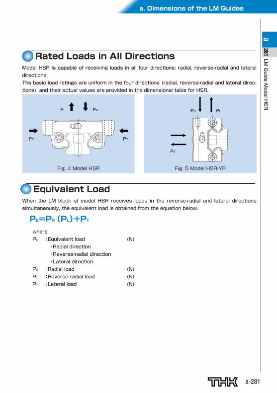
Rated Loads in All DirectionsModel HSR is capable of receiving loads in all four directions: radial, reverse-radial and lateral
directions.
The basic load ratings are uniform in the four directions (radial, reverse-radial and lateral direc-
tions), and their actual values are provided in the dimensional table for HSR.
PL
PT PT
PR
Fig. 4 Model HSR
PR
PT
PL
Fig. 5 Model HSR-YR
Equivalent LoadWhen the LM block of model HSR receives loads in the reverse-radial and lateral directions
simultaneously, the equivalent load is obtained from the equation below.
PE=PR(PL)+PT
where
PE :Equivalent load (N)
・Radial direction
・Reverse-radial direction
・Lateral direction
PR :Radial load (N)
PL :Reverse-radial load (N)
PT :Lateral load (N)
a-282
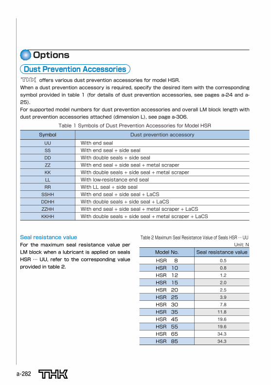
Seal resistance valueFor the maximum seal resistance value per
LM block when a lubricant is applied on seals
HSR … UU, refer to the corresponding value
provided in table 2.
Table 2 Maximum Seal Resistance Value of Seals HSR … UU
Model No.
HSR 8
HSR 10
HSR 12
HSR 15
HSR 20
HSR 25
HSR 30
HSR 35
HSR 45
HSR 55
HSR 65
HSR 85
Seal resistance value
0.5
0.8
1.2
2.0
2.5
3.9
7.8
11.8
19.6
19.6
34.3
34.3
Unit: N
Options
offers various dust prevention accessories for model HSR.
When a dust prevention accessory is required, specify the desired item with the corresponding
symbol provided in table 1 (for details of dust prevention accessories, see pages a-24 and a-
25).
For supported model numbers for dust prevention accessories and overall LM block length with
dust prevention accessories attached (dimension L), see page a-306.
Dust Prevention Accessories
Table 1 Symbols of Dust Prevention Accessories for Model HSR
Symbol
UU
SS
DD
ZZ
KK
LL
RR
SSHH
DDHH
ZZHH
KKHH
Dust prevention accessory
With end seal
With end seal + side seal
With double seals + side seal
With end seal + side seal + metal scraper
With double seals + side seal + metal scraper
With low-resistance end seal
With LL seal + side seal
With end seal + side seal + LaCS
With double seals + side seal + LaCS
With end seal + side seal + metal scraper + LaCS
With double seals + side seal + metal scraper + LaCS
a. Dimensions of the LM Guides
a-283
LMGuideModelHSR
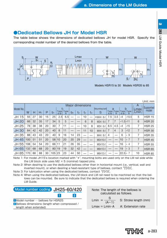
a283●Dedicated Bellows JH for Model HSR
The table below shows the dimensions of dedicated bellows JH for model HSR. Specify the
corresponding model number of the desired bellows from the table.
WS a
t1
S
b
HP
b1W
b2
W
H1 H1t4 t2t3
P
LmaxLmin
Models HSR35 to 85Models HSR15 to 30
JH 15
JH 20
JH 25
JH 30
JH 35
JH 45
JH 55
JH 65
JH 85
55
66
78
84
88
100
108
132
170
27
32
38
42
43
51
54
68
88
30
35
38
42
43
51
54
68
88
15
17
20
20
20
20
20
20
30
25
34
30
40
40
58
66
80
105
2.5
5
7
8
9
10
11
19
23
6.5
5
11
11
16
20
21
19
23
—
—
—
—
14
20
26
32
44
—
—
—
—
23
29
35
42
50
10
6
10
11
—
—
—
—
—
—
8
8
10
—
—
—
—
—
7.5
7
8.5
7
4
—
—
—
—
3.5
7
4.5
4
—
—
—
—
—
HSR 15
HSR 20
HSR 25
HSR 30
HSR 35
HSR 45
HSR 55
HSR 65
HSR 85
Model No.W H H1 P b1 Type
A/B
t1TypeR b2 t2 t3 t4 Type
A/BTypeRS
Supportedmodel
Lmin = S: Stroke length (mm)
Lmax = Lmin・A A: Extension rate
S (A-1)
Note: The length of the bellows is calculated as follows.
Model number coding JH25-60/420
zModel number … bellows for HSR25 xBellows dimensions (length when compressed /length when extended)
z x
Major dimensionsMounting bolt a
–4
–1.5
–4
3
6
10
16
19
22.5
–10.5
–11
–15
–12
– 9
– 7
– 4
– 3
– 7
TypeA/B
TypeR
b
*M4✕ 8R
M3✕ 6R
M3✕ 6R
M4✕ 8R
M4✕ 8R
M5✕10R
M5✕10R
M6✕12R
M6✕12R
5
6
7
7
7
7
7
7
10
ALmaxLmin
Note 1: For model JH15's location marked with "*", mounting bolts are used only on the LM rail side whilethe LM block side uses M2 ×5 (nominal) tapped pins.
Note 2: When desiring to use the dedicated bellows other than in horizontal mount (i.e., vertical, wall andinverted mount), or when desiring a heat-resistant type of bellows, contact .
Note 3: For lubrication when using the dedicated bellows, contact .Note 4: When using the dedicated bellows, the LM block and LM rail need to be machined so that the bel-
lows can be mounted. Be sure to indicate that the dedicated bellows is required when ordering theLM Guide.
Unit: mm
a-284
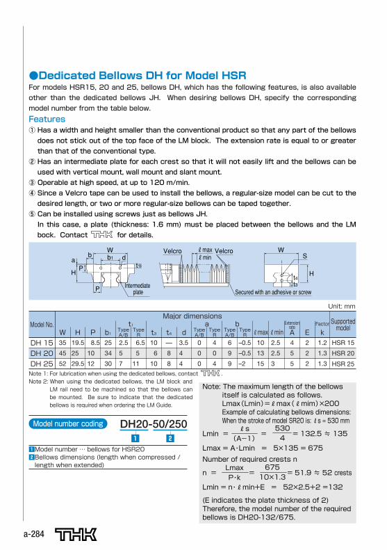
●Dedicated Bellows DH for Model HSRFor models HSR15, 20 and 25, bellows DH, which has the following features, is also available
other than the dedicated bellows JH. When desiring bellows DH, specify the corresponding
model number from the table below.
Wd
t1S
Ht4t3
b
HP
a b1W
P
RmaxRmin
VelcroVelcro
Intermediate plate Secured with an adhesive or screw
Features① Has a width and height smaller than the conventional product so that any part of the bellows
does not stick out of the top face of the LM block. The extension rate is equal to or greater
than that of the conventional type.
② Has an intermediate plate for each crest so that it will not easily lift and the bellows can be
used with vertical mount, wall mount and slant mount.
③ Operable at high speed, at up to 120 m/min.
④ Since a Velcro tape can be used to install the bellows, a regular-size model can be cut to the
desired length, or two or more regular-size bellows can be taped together.
⑤ Can be installed using screws just as bellows JH.
In this case, a plate (thickness: 1.6 mm) must be placed between the bellows and the LM
bock. Contact for details.
DH 15
DH 20
DH 25
35
45
52
19.5
25
29.5
8.5
10
12
25
34
30
2.5
5
7
6.5
5
11
10
6
10
—
8
8
3.5
4
4
0
0
0
4
0
4
HSR 15
HSR 20
HSR 25
Model No.W H P b1 Type
A/B
t1TypeR t3 t4 d Type
A/BTypeR
6
9
9
–0.5
–0.5
–2
TypeA/B
TypeR RmaxRmin A E k
Supportedmodel
Major dimensionsa b
10
13
15
2.5
2.5
3
4
5
5
2
2
2
1.2
1.3
1.3
Extensionrate
Factor
Unit: mm
Note 1: For lubrication when using the dedicated bellows, contact .Note 2: When using the dedicated bellows, the LM block and
LM rail need to be machined so that the bellows canbe mounted. Be sure to indicate that the dedicatedbellows is required when ordering the LM Guide.
Lmin = = = 132.5 ≒ 135
Lmax = A・Lmin = 5×135 = 675
Rs (A-1)
Note: The maximum length of the bellows itself is calculated as follows. Lmax(Lmin)=Rmax(Rmim)×200 Example of calculating bellows dimensions: When the stroke of model SR20 is: Rs = 530 mm
Number of required crests n
530 4
n = = = 51.9 ≒ 52 crests
Lmin = n・Rmin+E = 52×2.5+2 =132
(E indicates the plate thickness of 2) Therefore, the model number of the required bellows is DH20-132/675.
Lmax P・k
675 10×1.3
Model number coding DH20-50/250
zModel number … bellows for HSR20xBellows dimensions (length when compressed /length when extended)
z x
a. Dimensions of the LM Guides
a-285
LMGuideModelHSR
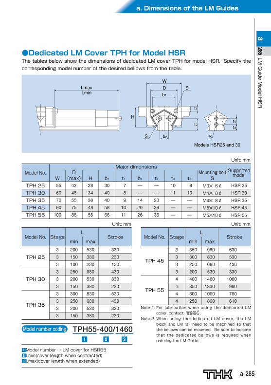
a285●Dedicated LM Cover TPH for Model HSR
The tables below show the dimensions of dedicated LM cover TPH for model HSR. Specify the
corresponding model number of the desired bellows from the table.
S
SS
LmaxLmin
WDb1
b2
t2
t1
t4t3
H
Models HSR25 and 30
TPH 25
TPH 30
TPH 35
TPH 45
TPH 55
55
60
70
90
100
42
48
55
75
88
28
34
38
48
55
30
40
40
58
66
7
8
9
10
11
—
—
14
20
26
—
—
23
29
35
10
11
—
—
—
8
10
—
—
—
M3✕ 6R
M4✕ 8R
M4✕ 8R
M5✕10R
M5✕10R
HSR 25
HSR 30
HSR 35
HSR 45
HSR 55
Model No.W (max) H b1 t1 b2 t2 t3 t4 S
Supportedmodel
Major dimensionsD Mounting bolt
Unit: mm
TPH 25
TPH 30
TPH 35
3
3
3
3
3
3
3
3
3
3
200
150
100
250
200
150
300
250
200
150
530
380
230
680
530
380
830
680
530
380
330
230
130
430
330
230
530
430
330
230
Model No. Stagemin max
StrokeL
Unit: mm
TPH 45
TPH 55
3
3
3
3
4
4
4
4
350
300
250
200
400
350
300
250
980
830
680
530
1460
1330
1060
860
630
530
430
330
1060
980
760
610
Model No. Stagemin max
StrokeL
Unit: mm
Note 1: For lubrication when using the dedicated LMcover, contact .
Note 2: When using the dedicated LM cover, the LMblock and LM rail need to be machined so thatthe bellows can be mounted. Be sure to indicatethat the dedicated bellows is required whenordering the LM Guide.
Model number coding TPH55-400/1460
zModel number … LM cover for HSR55xLmin(cover length when contracted)cLmax(cover length when extended)
z x c
a-286
When QZ Lubricator is required, specify the desired type with the corresponding symbol indi-
cated in table 4 (for details of QZ Lubricator, see pages a-19 and a-20).
For supported LM Guide model numbers for QZ Lubricator and overall LM block length with QZ
Lubricator attached (dimension L), see page a-307.
QZ LubricatorTM
Table 4 Parts Symbols for Model HSR with QZ Lubricator Attached
Symbol
QZUU
QZSS
QZDD
QZZZ
QZKK
QZSSHH
QZDDHH
QZZZHH
QZKKHH
Dust prevention accessories for LM Guide with QZ Lubricator attached
With end seal
With end seal + side seal
With double seals + side seal
With end seal + side seal + metal scraper + QZ
With double seals + side seal + metal scraper + QZ
With end seal + side seal + LaCS + QZ
With double seals + side seal + LaCS + QZ
With end seal + side seal + metal scraper + LaCS + QZ
With double seals + side seal + metal scraper + LaCS + QZ
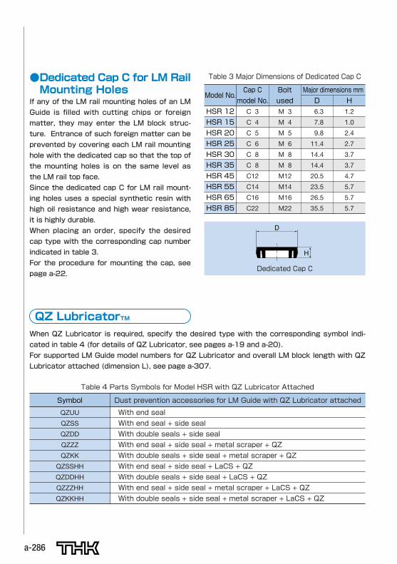
●Dedicated Cap C for LM RailMounting Holes
If any of the LM rail mounting holes of an LM
Guide is filled with cutting chips or foreign
matter, they may enter the LM block struc-
ture. Entrance of such foreign matter can be
prevented by covering each LM rail mounting
hole with the dedicated cap so that the top of
the mounting holes is on the same level as
the LM rail top face.
Since the dedicated cap C for LM rail mount-
ing holes uses a special synthetic resin with
high oil resistance and high wear resistance,
it is highly durable.
When placing an order, specify the desired
cap type with the corresponding cap number
indicated in table 3.
For the procedure for mounting the cap, see
page a-22.
Table 3 Major Dimensions of Dedicated Cap C
Model No.Cap C
model No.
Bolt
used
Major dimensions mm
D H
HSR 12
HSR 15
HSR 20
HSR 25
HSR 30
HSR 35
HSR 45
HSR 55
HSR 65
HSR 85
C 3 M 3 6.3 1.2
C 4 M 4 7.8 1.0
C 5 M 5 9.8 2.4
C 6 M 6 11.4 2.7
C 8 M 8 14.4 3.7
C 8 M 8 14.4 3.7
C12 M12 20.5 4.7
C14 M14 23.5 5.7
C16 M16 26.5 5.7
C22 M22 35.5 5.7
D
H
Dedicated Cap C
a. Dimensions of the LM Guides
a-287
LMGuideModelHSR
a287
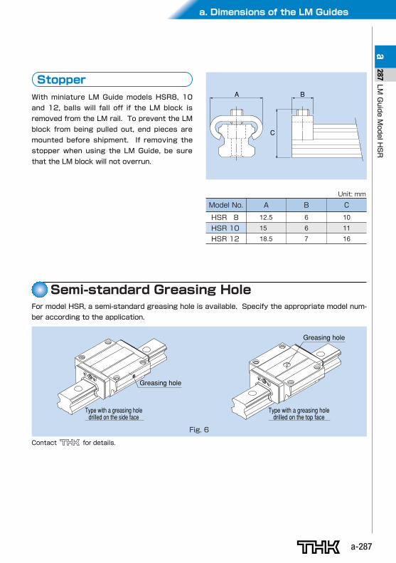
With miniature LM Guide models HSR8, 10
and 12, balls will fall off if the LM block is
removed from the LM rail. To prevent the LM
block from being pulled out, end pieces are
mounted before shipment. If removing the
stopper when using the LM Guide, be sure
that the LM block will not overrun.
B
C
A
Stopper
Model No.
HSR 8
HSR 10
HSR 12
A
12.5
15
18.5
B
6
6
7
C
10
11
16
Unit: mm
For model HSR, a semi-standard greasing hole is available. Specify the appropriate model num-
ber according to the application.
Greasing hole
Greasing hole
Type with a greasing hole drilled on the side face
Type with a greasing hole drilled on the top face
Fig. 6
Contact for details.
Semi-standard Greasing Hole
a-288
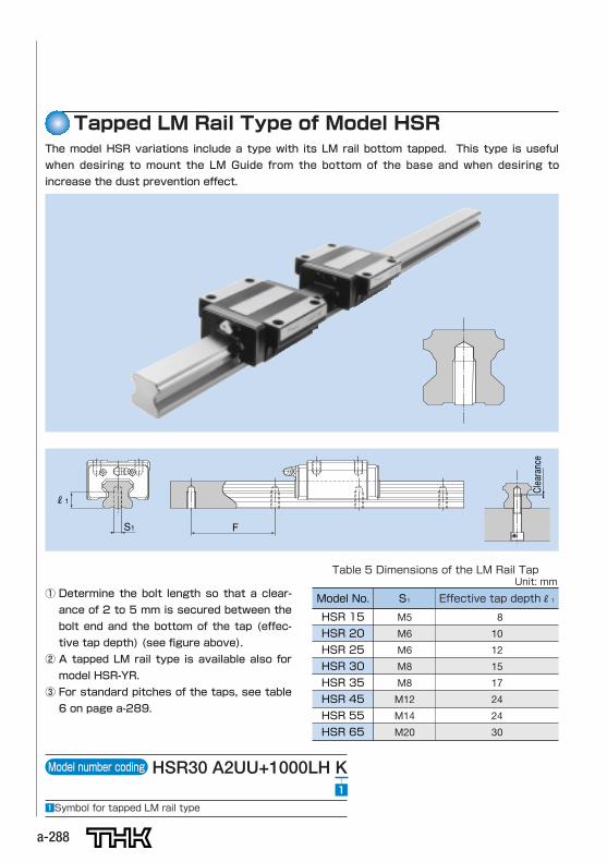
Table 5 Dimensions of the LM Rail Tap
Model No.
HSR 15
HSR 20
HSR 25
HSR 30
HSR 35
HSR 45
HSR 55
HSR 65
S1
M5
M6
M6
M8
M8
M12
M14
M20
Effective tap depthR1
8
10
12
15
17
24
24
30
Unit: mm
Clearance
S1 F
R1
① Determine the bolt length so that a clear-
ance of 2 to 5 mm is secured between the
bolt end and the bottom of the tap (effec-
tive tap depth) (see figure above).
② A tapped LM rail type is available also for
model HSR-YR.
③ For standard pitches of the taps, see table
6 on page a-289.
Model number coding HSR30 A2UU+1000LH K
zSymbol for tapped LM rail type
z
The model HSR variations include a type with its LM rail bottom tapped. This type is useful
when desiring to mount the LM Guide from the bottom of the base and when desiring to
increase the dust prevention effect.
Tapped LM Rail Type of Model HSR
a. Dimensions of the LM Guides
a-289
LMGuideModelHSR
a289
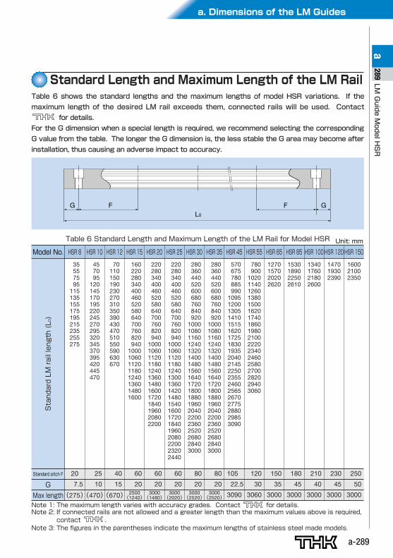
Table 6 Standard Length and Maximum Length of the LM Rail for Model HSR Unit: mm
Model No.
Standard pitch F 20 25 40 60 60 60 80 80 105 120 150 180 210 230 250
7.5 10 15 20 20 20 20 20 22.5 30 35 45 40 45 50
(275)(470)(670) 2500(1240)
3000(1480)
3000(2020)
3000(2520)
3000(2520) 3090 3060 3000 3000 3000 3000 3000
G
Max length
HSR 8
35557595
115135155175195215235255275
HSR 10
457095
120145170195220245270295320345370395420445470
HSR 12
70110150190230270310350390430470510550590630670
HSR 15
160220280340400460520580640700760820940
10001060112011801240136014801600
HSR 20
220280340400460520580640700760820940
1000106011201180124013601480160017201840196020802200
HSR 25
220280340400460520580640700760820940
100010601120118012401300136014201480154016001720184019602080220023202440
HSR 30
280360440520600680760840920
10001080116012401320140014801560164017201800188019602040220023602520268028403000
HSR 35
280360440520600680760840920
10001080116012401320140014801560164017201800188019602040220023602520268028403000
HSR 45
570675780885990
10951200130514101515162017251830193520402145225023552460256526702775288029853090
HSR 55
780900
102011401260138015001620174018601980210022202340246025802700282029403060
HSR 65
1270157020202620
HSR 85
1530189022502610
HSR 100
1340176021802600
HSR 120
147019302390
HSR 150
160021002350
Table 6 shows the standard lengths and the maximum lengths of model HSR variations. If the
maximum length of the desired LM rail exceeds them, connected rails will be used. Contact
for details.
For the G dimension when a special length is required, we recommend selecting the corresponding
G value from the table. The longer the G dimension is, the less stable the G area may become after
installation, thus causing an adverse impact to accuracy.
Standard Length and Maximum Length of the LM Rail
L0F FG G
StandardLMraillength(L
0)
Note 1: The maximum length varies with accuracy grades. Contact for details.Note 2: If connected rails are not allowed and a greater length than the maximum values above is required,
contact .Note 3: The figures in the parentheses indicate the maximum lengths of stainless steel made models.
a. Dimensions of the LM Guides
a-291
LMGuideModelHSR
a291
a-290
W2 W1
T1
W2 W1
WB
(K) M
T
WB4-S 4-S
T1
M
t T
(K)
φd1
φd2
F
N
hM1
(E) L1L
C
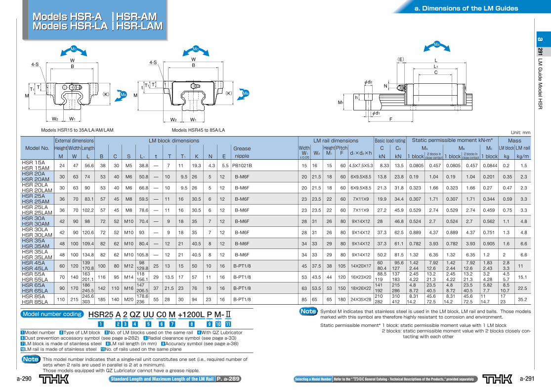
Note Symbol M indicates that stainless steel is used in the LM block, LM rail and balls. Those modelsmarked with this symbol are therefore highly resistant to corrosion and environment.
Static permissible moment* 1 block: static permissible moment value with 1 LM block2 blocks: static permissible moment value with 2 blocks closely con-
tacting with each other
Model number coding HSR25 A 2 QZ UU C0 M +1200L P M-Ⅱ
zModel number xType of LM block cNo. of LM blocks used on the same rail vWith QZ LubricatorbDust prevention accessory symbol (see page a-282) nRadial clearance symbol (see page a-33)mLM block is made of stainless steel ,LM rail length (in mm) .Accuracy symbol (see page a-38)⁄0LM rail is made of stainless steel ⁄1No. of rails used on the same plane
z ⁄0 ⁄1.,v b n mcx
Note This model number indicates that a single-rail unit constitutes one set (i.e., required number ofsets when 2 rails are used in parallel is 2 at a minimum).Those models equipped with QZ Lubricator cannot have a grease nipple.
Standard Length and Maximum Length of the LM Rail P. a-289 Selecting a Model Number Refer to the " General Catalog - Technical Descriptions of the Products," provided separately
Models HSR-A HSR-AMModels HSR-LA HSR-LAMModels HSR-A HSR-AMModels HSR-LA HSR-LAM
Model No.
External dimensions LM block dimensions
Height
M
Width
W
Length
L B C S L1 t T T1 K N E
Grease
nipple
WidthW1
±0.05W2
HeightM1
PitchF
C
kN
C0
kN
LM rail dimensions Basic load rating Static permissible moment kN-m* Mass
LM block
kg
LM rail
kg/m
MA
1 block
MC
1 blockHSR 15AHSR 15AMHSR 20AHSR 20AMHSR 20LAHSR 20LAMHSR 25AHSR 25AMHSR 25LAHSR 25LAMHSR 30AHSR 30AMHSR 30LAHSR 30LAMHSR 35AHSR 35AMHSR 35LAHSR 35LAMHSR 45AHSR 45LAHSR 55AHSR 55LAHSR 65AHSR 65LAHSR 85AHSR 85LA
24
30
30
36
36
42
42
48
48
60
70
90
110
47
63
63
70
70
90
90
100
100
120
140
170
215
56.6
74
90
83.1
102.2
98
120.6
109.4
134.8
139170.8163201.1186245.5245.6303
38
53
53
57
57
72
72
82
82
100
116
142
185
30
40
40
45
45
52
52
62
62
80
95
110
140
M5
M6
M6
M8
M8
M10
M10
M10
M10
M12
M14
M16
M20
38.8
50.8
66.8
59.5
78.6
70.4
93
80.4
105.8
98129.8118156.1147206.5178.6236
—
—
—
—
—
—
—
—
—
25
29
37
55
7
10
10
11
11
9
9
12
12
13
13.5
21.5
28
11
9.5
9.5
16
16
18
18
21
21
15
17
23
30
19.3
26
26
30.5
30.5
35
35
40.5
40.5
50
57
76
94
4.3
5
5
6
6
7
7
8
8
10
11
19
23
5.5
12
12
12
12
12
12
12
12
16
16
16
16
PB1021B
B-M6F
B-M6F
B-M6F
B-M6F
B-M6F
B-M6F
B-M6F
B-M6F
B-PT1/8
B-PT1/8
B-PT1/8
B-PT1/8
Unit: mm
15
20
20
23
23
28
28
34
34
45
53
63
85
16
21.5
21.5
23.5
23.5
31
31
33
33
37.5
43.5
53.5
65
15
18
18
22
22
26
26
29
29
38
44
53
65
60
60
60
60
60
80
80
80
80
105
120
150
180
4.5✕7.5✕5.3
6✕9.5✕8.5
6✕9.5✕8.5
7✕11✕9
7✕11✕9
9✕14✕12
9✕14✕12
9✕14✕12
9✕14✕12
14✕20✕17
16✕23✕20
18✕26✕22
24✕35✕28
8.33
13.8
21.3
19.9
27.2
28
37.3
37.3
50.2
6080.488.5
119141192210282
13.5
23.8
31.8
34.4
45.9
46.8
62.5
61.1
81.5
95.6127137183215286310412
0.0805
0.19
0.323
0.307
0.529
0.524
0.889
0.782
1.32
1.422.442.454.224.88.728.31
14.2
0.457
1.04
1.66
1.71
2.74
2.7
4.37
3.93
6.35
7.9212.613.221.323.540.545.672.5
MB
1 block
0.0805
0.19
0.323
0.307
0.529
0.524
0.889
0.782
1.32
1.422.442.454.224.88.728.31
14.2
0.457
1.04
1.66
1.71
2.74
2.7
4.37
3.93
6.35
7.9212.613.221.323.540.545.672.5
0.0844
0.201
0.27
0.344
0.459
0.562
0.751
0.905
1.2
1.832.433.24.285.827.7
1114.7
0.2
0.35
0.47
0.59
0.75
1.1
1.3
1.6
2
2.83.34.55.78.5
10.71723
1.5
2.3
2.3
3.3
3.3
4.8
4.8
6.6
6.6
11
15.1
22.5
35.2
Models HSR15 to 35A/LA/AM/LAM Models HSR45 to 85A/LA
2 blocks inclose contact
2 blocks inclose contact
d1×d2×h
a. Dimensions of the LM Guides
a-293
LMGuideModelHSR
a293
a-292 Standard Length and Maximum Length of the LM Rail P. a-289 Selecting a Model Number Refer to the " General Catalog - Technical Descriptions of the Products," provided separately
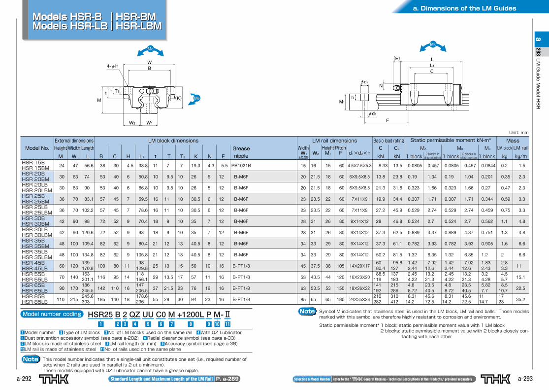
Models HSR-B HSR-BMModels HSR-LB HSR-LBMModels HSR-B HSR-BMModels HSR-LB HSR-LBM
W2 W1
WB
M
T T1t
4-φH
(K)
φd1
φd2
F
N
hM1
(E) L1L
C
Note Symbol M indicates that stainless steel is used in the LM block, LM rail and balls. Those modelsmarked with this symbol are therefore highly resistant to corrosion and environment.
Static permissible moment* 1 block: static permissible moment value with 1 LM block2 blocks: static permissible moment value with 2 blocks closely con-
tacting with each other
Model number coding HSR25 B 2 QZ UU C0 M +1200L P M-Ⅱ
zModel number xType of LM block cNo. of LM blocks used on the same rail vWith QZ LubricatorbDust prevention accessory symbol (see page a-282) nRadial clearance symbol (see page a-33)mLM block is made of stainless steel ,LM rail length (in mm) .Accuracy symbol (see page a-38)⁄0LM rail is made of stainless steel ⁄1No. of rails used on the same plane
z ⁄0 ⁄1.,v b n mcx
Note This model number indicates that a single-rail unit constitutes one set (i.e., required number ofsets when 2 rails are used in parallel is 2 at a minimum).Those models equipped with QZ Lubricator cannot have a grease nipple.
Model No.
External dimensions LM block dimensions
Height
M
Width
W
Length
L B C H L1 t T T1 K N E
Grease
nipple
WidthW1
±0.05W2
HeightM1
PitchF
C
kN
C0
kN
LM rail dimensions Basic load rating Static permissible moment kN-m* Mass
LM block
kg
LM rail
kg/m
MA
1 block
MC
1 blockHSR 15BHSR 15BMHSR 20BHSR 20BMHSR 20LBHSR 20LBMHSR 25BHSR 25BMHSR 25LBHSR 25LBMHSR 30BHSR 30BMHSR 30LBHSR 30LBMHSR 35BHSR 35BMHSR 35LBHSR 35LBMHSR 45BHSR 45LBHSR 55BHSR 55LBHSR 65BHSR 65LBHSR 85BHSR 85LB
24
30
30
36
36
42
42
48
48
60
70
90
110
47
63
63
70
70
90
90
100
100
120
140
170
215
56.6
74
90
83.1
102.2
98
120.6
109.4
134.8
139170.8163201.1186245.5245.6303
38
53
53
57
57
72
72
82
82
100
116
142
185
30
40
40
45
45
52
52
62
62
80
95
110
140
4.5
6
6
7
7
9
9
9
9
11
14
16
18
38.8
50.8
66.8
59.5
78.6
70.4
93
80.4
105.8
98129.8118156.1147206.5178.6236
11
10
10
16
16
18
18
21
21
25
29
37
55
7
9.5
9.5
11
11
9
9
12
12
13
13.5
21.5
28
7
10
10
10
10
10
10
13
13
15
17
23
30
19.3
26
26
30.5
30.5
35
35
40.5
40.5
50
57
76
94
4.3
5
5
6
6
7
7
8
8
10
11
19
23
5.5
12
12
12
12
12
12
12
12
16
16
16
16
PB1021B
B-M6F
B-M6F
B-M6F
B-M6F
B-M6F
B-M6F
B-M6F
B-M6F
B-PT1/8
B-PT1/8
B-PT1/8
B-PT1/8
Unit: mm
15
20
20
23
23
28
28
34
34
45
53
63
85
16
21.5
21.5
23.5
23.5
31
31
33
33
37.5
43.5
53.5
65
15
18
18
22
22
26
26
29
29
38
44
53
65
60
60
60
60
60
80
80
80
80
105
120
150
180
4.5✕7.5✕5.3
6✕9.5✕8.5
6✕9.5✕8.5
7✕11✕9
7✕11✕9
9✕14✕12
9✕14✕12
9✕14✕12
9✕14✕12
14✕20✕17
16✕23✕20
18✕26✕22
24✕35✕28
8.33
13.8
21.3
19.9
27.2
28
37.3
37.3
50.2
6080.488.5
119141192210282
13.5
23.8
31.8
34.4
45.9
46.8
62.5
61.1
81.5
95.6127137183215286310412
0.0805
0.19
0.323
0.307
0.529
0.524
0.889
0.782
1.32
1.422.442.454.224.88.728.31
14.2
0.457
1.04
1.66
1.71
2.74
2.7
4.37
3.93
6.35
7.9212.613.221.323.540.545.672.5
MB
1 block
0.0805
0.19
0.323
0.307
0.529
0.524
0.889
0.782
1.32
1.422.442.454.224.88.728.31
14.2
0.457
1.04
1.66
1.71
2.74
2.7
4.37
3.93
6.35
7.9212.613.221.323.540.545.672.5
0.0844
0.201
0.27
0.344
0.459
0.562
0.751
0.905
1.2
1.832.433.24.285.827.7
1114.7
0.2
0.35
0.47
0.59
0.75
1.1
1.3
1.6
2
2.83.34.55.78.5
10.71723
1.5
2.3
2.3
3.3
3.3
4.8
4.8
6.6
6.6
11
15.1
22.5
35.2
2 blocks inclose contact
2 blocks inclose contact
d1×d2×h
W
W1
L1
C
L
W2
B
N
M
φd2
φd1
M1
4-S×R
F
h
φd
(K)
a-294
a. Dimensions of the LM Guides
a-295
LMGuideModelHSR
a295
Standard Length and Maximum Length of the LM Rail P. a-289 Selecting a Model Number Refer to the " General Catalog - Technical Descriptions of the Products," provided separately
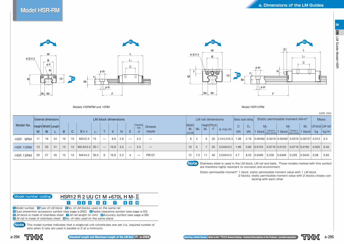
Model HSR-RMModel HSR-RM
Note Stainless steel is used in the LM block, LM rail and balls. Those models marked with this symbolare therefore highly resistant to corrosion and environment.
Static permissible moment* 1 block: static permissible moment value with 1 LM block2 blocks: static permissible moment value with 2 blocks closely con-
tacting with each other
Model number coding HSR12 R 2 UU C1 M +670L H M-Ⅱ
zModel number xType of LM block cNo. of LM blocks used on the same railvDust prevention accessory symbol (see page a-282) bRadial clearance symbol (see page a-33)nLM block is made of stainless steel mLM rail length (in mm) ,Accuracy symbol (see page a-38).LM rail is made of stainless steel ⁄0No. of rails used on the same plane
z ⁄0.,v b n mcx
Note This model number indicates that a single-rail unit constitutes one set (i.e., required number ofsets when 2 rails are used in parallel is 2 at a minimum).
L1
C
L
W1W2
φd2
φd1
M1
W
B
M
T
4-S×R
F
Nh
(E)
(K)
Model No.
External dimensions LM block dimensions
Height
M
Width
W
Length
L B C S×R L1 T K N E
Greasinghole
d
Grease
nipple
WidthW1
±0.05
W2
HeightM1
PitchF d1×d2×h
C
kN
C0
kN
LM rail dimensions Basic load rating Static permissible moment kN-m* Mass
LM block
kg
LM rail
kg/m
MA
1 block
MC
1 block
HSR 8RM
HSR 10RM
HSR 12RM
11
13
20
16
20
27
24
31
45
10
13
15
10
12
15
M2✕2.5
M2.6✕2.5
M4✕4.5
15
20.1
30.5
—
—
6
8.9
10.8
16.9
2.6
3.5
5.2
—
—
4
2.2
2.5
—
—
—
PB107
Unit: mm
8
10
12
4
5
7.5
6
7
11
20
25
40
2.4✕4.2✕2.3
3.5✕6✕3.3
3.5✕6✕4.5
1.08
1.96
4.7
2.16
3.82
8.53
0.00492
0.0123
0.0409
0.0319
0.0716
0.228
MB
1 block
0.00492
0.0123
0.0409
0.0319
0.0716
0.228
0.00727
0.0162
0.0445
0.012
0.025
0.08
0.3
0.45
0.83
Models HSR8RM and 10RM Model HSR12RM
2 blocks inclose contact
2 blocks inclose contact
a. Dimensions of the LM Guides
a-297
LMGuideModelHSR
a297
a-296 Standard Length and Maximum Length of the LM Rail P. a-289 Selecting a Model Number Refer to the " General Catalog - Technical Descriptions of the Products," provided separately
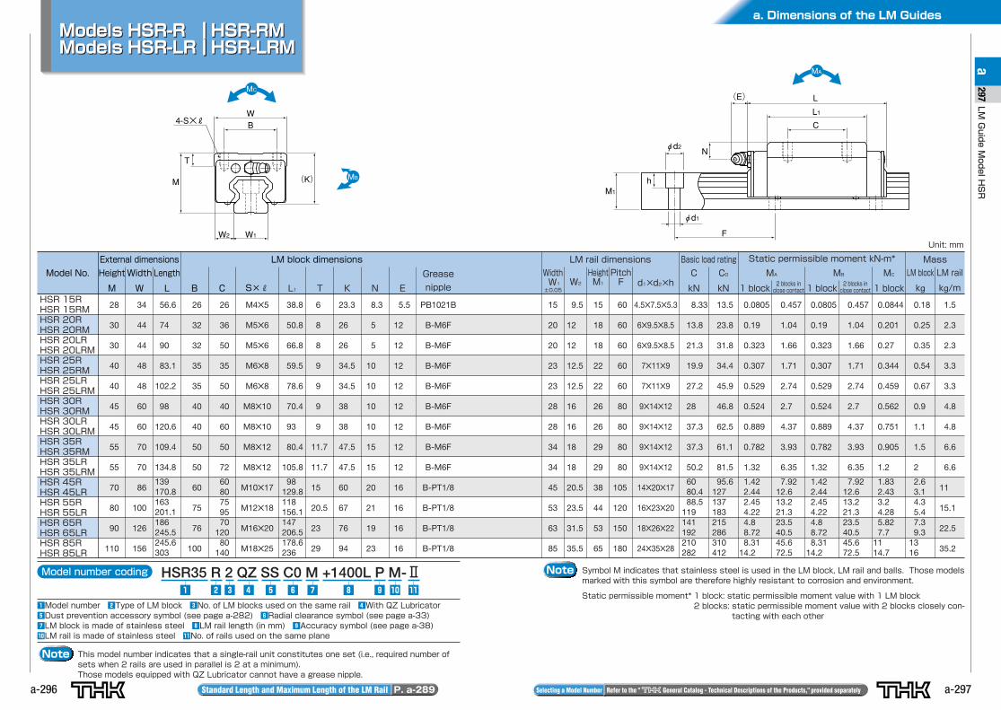
Note Symbol M indicates that stainless steel is used in the LM block, LM rail and balls. Those modelsmarked with this symbol are therefore highly resistant to corrosion and environment.
Static permissible moment* 1 block: static permissible moment value with 1 LM block2 blocks: static permissible moment value with 2 blocks closely con-
tacting with each other
Model number coding HSR35 R 2 QZ SS C0 M +1400L P M-Ⅱ
zModel number xType of LM block cNo. of LM blocks used on the same rail vWith QZ LubricatorbDust prevention accessory symbol (see page a-282) nRadial clearance symbol (see page a-33)mLM block is made of stainless steel ,LM rail length (in mm) .Accuracy symbol (see page a-38)⁄0LM rail is made of stainless steel ⁄1No. of rails used on the same plane
z ⁄0 ⁄1.,v b n mcx
Note This model number indicates that a single-rail unit constitutes one set (i.e., required number ofsets when 2 rails are used in parallel is 2 at a minimum).Those models equipped with QZ Lubricator cannot have a grease nipple.
W2 W1
WB
M
T
4-S×R
(K)
φd1
M1
φd2
F
N
h
(E)
L1
L
C
Model No.
External dimensions LM block dimensions
Height
M
Width
W
Length
L B C S×R L1 T K N E
Grease
nipple
WidthW1
±0.05W2
HeightM1
PitchF d1×d2×h
C
kN
C0
kN
LM rail dimensions Basic load rating Static permissible moment kN-m* Mass
LM block
kg
LM rail
kg/m
MA
1 block
MC
1 blockHSR 15RHSR 15RMHSR 20RHSR 20RMHSR 20LRHSR 20LRMHSR 25RHSR 25RMHSR 25LRHSR 25LRMHSR 30RHSR 30RMHSR 30LRHSR 30LRMHSR 35RHSR 35RMHSR 35LRHSR 35LRMHSR 45RHSR 45LRHSR 55RHSR 55LRHSR 65RHSR 65LRHSR 85RHSR 85LR
28
30
30
40
40
45
45
55
55
70
80
90
110
34
44
44
48
48
60
60
70
70
86
100
126
156
56.6
74
90
83.1
102.2
98
120.6
109.4
134.8
139170.8163201.1186245.5245.6303
26
32
32
35
35
40
40
50
50
60
75
76
100
26
36
50
35
50
40
60
50
72
6080759570
12080
140
M4✕5
M5✕6
M5✕6
M6✕8
M6✕8
M8✕10
M8✕10
M8✕12
M8✕12
M10✕17
M12✕18
M16✕20
M18✕25
38.8
50.8
66.8
59.5
78.6
70.4
93
80.4
105.8
98129.8118156.1147206.5178.6236
6
8
8
9
9
9
9
11.7
11.7
15
20.5
23
29
23.3
26
26
34.5
34.5
38
38
47.5
47.5
60
67
76
94
8.3
5
5
10
10
10
10
15
15
20
21
19
23
5.5
12
12
12
12
12
12
12
12
16
16
16
16
PB1021B
B-M6F
B-M6F
B-M6F
B-M6F
B-M6F
B-M6F
B-M6F
B-M6F
B-PT1/8
B-PT1/8
B-PT1/8
B-PT1/8
Unit: mm
15
20
20
23
23
28
28
34
34
45
53
63
85
9.5
12
12
12.5
12.5
16
16
18
18
20.5
23.5
31.5
35.5
15
18
18
22
22
26
26
29
29
38
44
53
65
60
60
60
60
60
80
80
80
80
105
120
150
180
4.5✕7.5✕5.3
6✕9.5✕8.5
6✕9.5✕8.5
7✕11✕9
7✕11✕9
9✕14✕12
9✕14✕12
9✕14✕12
9✕14✕12
14✕20✕17
16✕23✕20
18✕26✕22
24✕35✕28
8.33
13.8
21.3
19.9
27.2
28
37.3
37.3
50.2
6080.488.5
119141192210282
13.5
23.8
31.8
34.4
45.9
46.8
62.5
61.1
81.5
95.6127137183215286310412
0.0805
0.19
0.323
0.307
0.529
0.524
0.889
0.782
1.32
1.422.442.454.224.88.728.31
14.2
0.457
1.04
1.66
1.71
2.74
2.7
4.37
3.93
6.35
7.9212.613.221.323.540.545.672.5
MB
1 block
0.0805
0.19
0.323
0.307
0.529
0.524
0.889
0.782
1.32
1.422.442.454.224.88.728.31
14.2
0.457
1.04
1.66
1.71
2.74
2.7
4.37
3.93
6.35
7.9212.613.221.323.540.545.672.5
0.0844
0.201
0.27
0.344
0.459
0.562
0.751
0.905
1.2
1.832.433.24.285.827.7
1114.7
0.18
0.25
0.35
0.54
0.67
0.9
1.1
1.5
2
2.63.14.35.47.39.3
1316
1.5
2.3
2.3
3.3
3.3
4.8
4.8
6.6
6.6
11
15.1
22.5
35.2
Models HSR-R HSR-RMModels HSR-LR HSR-LRMModels HSR-R HSR-RMModels HSR-LR HSR-LRM
2 blocks inclose contact
2 blocks inclose contact
a. Dimensions of the LM Guides
a-299
LMGuideModelHSR
a299
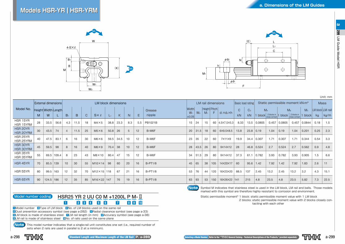
a-298
W2
W1
W
M
B1
B
4-S×R
(K)
φd1
M1
φd2
F
N
h
(E)
L1L
C
Model number coding HSR25 YR 2 UU C0 M +1200L P M-Ⅱ
zModel number xType of LM block cNo. of LM blocks used on the same railvDust prevention accessory symbol (see page a-282) bRadial clearance symbol (see page a-33)nLM block is made of stainless steel mLM rail length (in mm) ,Accuracy symbol (see page a-38).LM rail is made of stainless steel ⁄0No. of rails used on the same plane
z . ⁄0,mnbvcx
Note This model number indicates that a single-rail unit constitutes one set (i.e., required number ofsets when 2 rails are used in parallel is 2 at a minimum).
Models HSR-YR HSR-YRMModels HSR-YR HSR-YRM
Note Symbol M indicates that stainless steel is used in the LM block, LM rail and balls. Those modelsmarked with this symbol are therefore highly resistant to corrosion and environment.
Static permissible moment* 1 block: static permissible moment value with 1 LM block2 blocks: static permissible moment value with 2 blocks closely con-
tacting with each other
Model No.
External dimensions LM block dimensions
Height
M
Width
W
Length
L B1 B S×R L1C K N E
Grease
nipple
WidthW1
±0.05
LM rail dimensions Basic load rating Static permissible moment kN-m* Mass
W2
HeightM1
PitchF d1×d2×h
C0
kN
C
kN
LM block
kg
LM rail
kg/m
HSR 15YRHSR 15YRMHSR 20YRHSR 20YRMHSR 25YRHSR 25YRMHSR 30YRHSR 30YRMHSR 35YRHSR 35YRM
HSR 45YR
HSR 55YR
HSR 65YR
28
30
40
45
55
70
80
90
33.5
43.5
47.5
59.5
69.5
85.5
99.5
124.5
56.6
74
83.1
98
109.4
139
163
186
4.3
4
6
8
8
10
12
12
11.5
11.5
16
16
23
30
32
35
M4×5
M5×6
M6×6
M6×9
M8×10
M10×14
M12×15
M16×22
38.8
50.8
59.5
70.4
80.4
98
118
147
18
25
30
40
43
55
70
85
23.3
26
34.5
38
47
60
67
76
8.3
5
10
10
15
20
21
19
5.5
12
12
12
12
16
16
16
PB1021B
B-M6F
B-M6F
B-M6F
B-M6F
B-PT1/8
B-PT1/8
B-PT1/8
15
20
23
28
34
45
53
63
24
31.5
35
43.5
51.5
65
76
93
15
18
22
26
29
38
44
53
60
60
60
80
80
105
120
150
4.5✕7.5✕5.3
6✕9.5✕8.5
7✕11✕9
9✕14✕12
9✕14✕12
14✕20✕17
16✕23✕20
18✕26✕22
8.33
13.8
19.9
28
37.3
60
88.5
141
13.5
23.8
34.4
46.8
61.1
95.6
137
215
0.0805
0.19
0.307
0.524
0.782
1.42
2.45
4.8
0.457
1.04
1.71
2.7
3.93
7.92
13.2
23.5
0.0805
0.19
0.307
0.524
0.782
1.42
2.45
4.8
0.0844
0.201
0.344
0.562
0.905
1.83
3.2
5.82
0.457
1.04
1.71
2.7
3.93
7.92
13.2
23.5
0.18
0.25
0.54
0.9
1.5
2.6
4.3
7.3
1.5
2.3
3.3
4.8
6.6
11
15.1
22.5
Unit: mm
MA
1 block
MB
1 block
MC
1 block
Standard Length and Maximum Length of the LM Rail P. a-289 Selecting a Model Number Refer to the " General Catalog - Technical Descriptions of the Products," provided separately
2 blocks inclose contact
2 blocks inclose contact
a. Dimensions of the LM Guides
a-301
LMGuideModelHSR
a301
a-300
W2 W1 W2 W1
WB
M
TT1
WB6-S 6-S
(K) M
tTT1
(K)
φd1
M1
φd2
F
N
h
(E) L1L
C
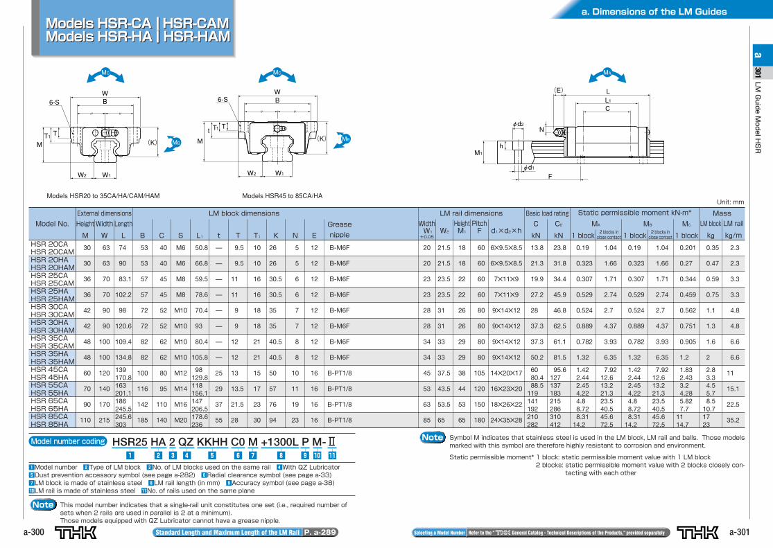
Note Symbol M indicates that stainless steel is used in the LM block, LM rail and balls. Those modelsmarked with this symbol are therefore highly resistant to corrosion and environment.
Static permissible moment* 1 block: static permissible moment value with 1 LM block2 blocks: static permissible moment value with 2 blocks closely con-
tacting with each other
Model number coding HSR25 HA 2 QZ KKHH C0 M +1300L P M-Ⅱ
zModel number xType of LM block cNo. of LM blocks used on the same rail vWith QZ LubricatorbDust prevention accessory symbol (see page a-282) nRadial clearance symbol (see page a-33)mLM block is made of stainless steel ,LM rail length (in mm) .Accuracy symbol (see page a-38)⁄0LM rail is made of stainless steel ⁄1No. of rails used on the same plane
z ⁄0 ⁄1.,v b n mcx
Note This model number indicates that a single-rail unit constitutes one set (i.e., required number ofsets when 2 rails are used in parallel is 2 at a minimum).Those models equipped with QZ Lubricator cannot have a grease nipple.
Models HSR-CA HSR-CAMModels HSR-HA HSR-HAMModels HSR-CA HSR-CAMModels HSR-HA HSR-HAM
Standard Length and Maximum Length of the LM Rail P. a-289 Selecting a Model Number Refer to the " General Catalog - Technical Descriptions of the Products," provided separately
Model No.
External dimensions LM block dimensions
Height
M
Width
W
Length
L B C S L1 t T T1 K N E
Grease
nipple
WidthW1
±0.05W2
HeightM1
PitchF
C
kN
C0
kN
LM rail dimensions Basic load rating Static permissible moment kN-m* Mass
LM block
kg
LM rail
kg/m
MA
1 block
MC
1 blockHSR 20CAHSR 20CAMHSR 20HAHSR 20HAMHSR 25CAHSR 25CAMHSR 25HAHSR 25HAMHSR 30CAHSR 30CAMHSR 30HAHSR 30HAMHSR 35CAHSR 35CAMHSR 35HAHSR 35HAMHSR 45CAHSR 45HAHSR 55CAHSR 55HAHSR 65CAHSR 65HAHSR 85CAHSR 85HA
30
30
36
36
42
42
48
48
60
70
90
110
63
63
70
70
90
90
100
100
120
140
170
215
74
90
83.1
102.2
98
120.6
109.4
134.8
139170.8163201.1186245.5245.6303
53
53
57
57
72
72
82
82
100
116
142
185
40
40
45
45
52
52
62
62
80
95
110
140
M6
M6
M8
M8
M10
M10
M10
M10
M12
M14
M16
M20
50.8
66.8
59.5
78.6
70.4
93
80.4
105.8
98129.8118156.1147206.5178.6236
—
—
—
—
—
—
—
—
25
29
37
55
9.5
9.5
11
11
9
9
12
12
13
13.5
21.5
28
10
10
16
16
18
18
21
21
15
17
23
30
26
26
30.5
30.5
35
35
40.5
40.5
50
57
76
94
5
5
6
6
7
7
8
8
10
11
19
23
12
12
12
12
12
12
12
12
16
16
16
16
B-M6F
B-M6F
B-M6F
B-M6F
B-M6F
B-M6F
B-M6F
B-M6F
B-PT1/8
B-PT1/8
B-PT1/8
B-PT1/8
Unit: mm
20
20
23
23
28
28
34
34
45
53
63
85
21.5
21.5
23.5
23.5
31
31
33
33
37.5
43.5
53.5
65
18
18
22
22
26
26
29
29
38
44
53
65
60
60
60
60
80
80
80
80
105
120
150
180
6✕9.5✕8.5
6✕9.5✕8.5
7✕11✕9
7✕11✕9
9✕14✕12
9✕14✕12
9✕14✕12
9✕14✕12
14✕20✕17
16✕23✕20
18✕26✕22
24✕35✕28
13.8
21.3
19.9
27.2
28
37.3
37.3
50.2
6080.488.5
119141192210282
23.8
31.8
34.4
45.9
46.8
62.5
61.1
81.5
95.6127137183215286310412
0.19
0.323
0.307
0.529
0.524
0.889
0.782
1.32
1.422.442.454.224.88.728.31
14.2
1.04
1.66
1.71
2.74
2.7
4.37
3.93
6.35
7.9212.613.221.323.540.545.672.5
MB
1 block
0.19
0.323
0.307
0.529
0.524
0.889
0.782
1.32
1.422.442.454.224.88.728.31
14.2
1.04
1.66
1.71
2.74
2.7
4.37
3.93
6.35
7.9212.613.221.323.540.545.672.5
0.201
0.27
0.344
0.459
0.562
0.751
0.905
1.2
1.832.433.24.285.827.7
1114.7
0.35
0.47
0.59
0.75
1.1
1.3
1.6
2
2.83.34.55.78.5
10.71723
2.3
2.3
3.3
3.3
4.8
4.8
6.6
6.6
11
15.1
22.5
35.2
Models HSR20 to 35CA/HA/CAM/HAM Models HSR45 to 85CA/HA
2 blocks inclose contact
2 blocks inclose contact
d1×d2×h
a. Dimensions of the LM Guides
a-303
LMGuideModelHSR
a303
a-302
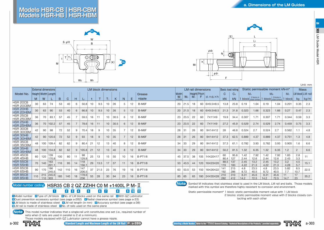
Models HSR-CB HSR-CBMModels HSR-HB HSR-HBM
W2 W1
W
M
t T T1
B6-φH
(K)
φd1
M1
φd2
F
N
h
(E)
L1
L
C
Note Symbol M indicates that stainless steel is used in the LM block, LM rail and balls. Those modelsmarked with this symbol are therefore highly resistant to corrosion and environment.
Static permissible moment* 1 block: static permissible moment value with 1 LM block2 blocks: static permissible moment value with 2 blocks closely con-
tacting with each other
Model number coding HSR35 CB 2 QZ ZZHH C0 M +1400L P M-Ⅱ
zModel number xType of LM block cNo. of LM blocks used on the same rail vWith QZ LubricatorbDust prevention accessory symbol (see page a-282) nRadial clearance symbol (see page a-33)mLM block is made of stainless steel ,LM rail length (in mm) .Accuracy symbol (see page a-38)⁄0LM rail is made of stainless steel ⁄1No. of rails used on the same plane
z ⁄0 ⁄1.,v b n mcx
Note This model number indicates that a single-rail unit constitutes one set (i.e., required number ofsets when 2 rails are used in parallel is 2 at a minimum).Those models equipped with QZ Lubricator cannot have a grease nipple.
Standard Length and Maximum Length of the LM Rail P. a-289 Selecting a Model Number Refer to the " General Catalog - Technical Descriptions of the Products," provided separately
Model No.
External dimensions LM block dimensions
Height
M
Width
W
Length
L B C H L1 t T T1 K N E
Grease
nipple
WidthW1
±0.05W2
HeightM1
PitchF
C
kN
C0
kN
LM rail dimensions Basic load rating Static permissible moment kN-m* Mass
LM block
kg
LM rail
kg/m
MA
1 block
MC
1 blockHSR 20CBHSR 20CBMHSR 20HBHSR 20HBMHSR 25CBHSR 25CBMHSR 25HBHSR 25HBMHSR 30CBHSR 30CBMHSR 30HBHSR 30HBMHSR 35CBHSR 35CBMHSR 35HBHSR 35HBMHSR 45CBHSR 45HBHSR 55CBHSR 55HBHSR 65CBHSR 65HBHSR 85CBHSR 85HB
30
30
36
36
42
42
48
48
60
70
90
110
63
63
70
70
90
90
100
100
120
140
170
215110
74
90
83.1
102.2
98
120.6
109.4
134.8
139170.8163201.1186245.5245.6303
53
53
57
57
72
72
82
82
100
116
142
185
40
40
45
45
52
52
62
62
80
95
110
140
6
6
7
7
9
9
9
9
11
14
16
18
50.8
66.8
59.5
78.6
70.4
93
80.4
105.8
98129.8118156.1147206.5178.6236
10
10
16
16
18
18
21
21
25
29
37
55
9.5
9.5
11
11
9
9
12
12
13
13.5
21.5
28
10
10
10
10
10
10
13
13
15
17
23
30
26
26
30.5
30.5
35
35
40
40
50
57
76
94
5
5
6
6
7
7
8
8
10
11
19
23
12
12
12
12
12
12
12
12
16
16
16
16
B-M6F
B-M6F
B-M6F
B-M6F
B-M6F
B-M6F
B-M6F
B-M6F
B-PT1/8
B-PT1/8
B-PT1/8
B-PT1/8
Unit: mm
20
20
23
23
28
28
34
34
45
53
63
85
21.5
21.5
23.5
23.5
31
31
33
33
37.5
43.5
53.5
65
18
18
22
22
26
26
29
29
38
44
53
65
60
60
60
60
80
80
80
80
105
120
150
180
6✕9.5✕8.5
6✕9.5✕8.5
7✕11✕9
7✕11✕9
9✕14✕12
9✕14✕12
9✕14✕12
9✕14✕12
14✕20✕17
16✕23✕20
18✕26✕22
24✕35✕28
13.8
21.3
19.9
27.2
28
37.3
37.3
50.2
6080.488.5
119141192210282
23.8
31.8
34.4
45.9
46.8
62.5
61.1
81.5
95.6127137183215286310412
0.19
0.323
0.307
0.529
0.524
0.889
0.782
1.32
1.422.442.454.224.88.728.31
14.2
1.04
1.66
1.71
2.74
2.7
4.37
3.93
6.35
7.9212.613.221.323.540.545.672.5
MB
1 block
0.19
0.323
0.307
0.529
0.524
0.889
0.782
1.32
1.422.442.454.224.88.728.31
14.2
1.04
1.66
1.71
2.74
2.7
4.37
3.93
6.35
7.9212.613.221.323.540.545.672.5
0.201
0.27
0.344
0.459
0.562
0.751
0.905
1.2
1.832.433.24.285.827.7
1114.7
0.35
0.47
0.59
0.75
1.1
1.3
1.6
2
2.83.34.55.78.5
10.71723
2.3
2.3
3.3
3.3
4.8
4.8
6.6
6.6
11
15.1
22.5
35.2
Models HSR-CB HSR-CBMModels HSR-HB HSR-HBM
2 blocks inclose contact
2 blocks inclose contact
d1×d2×h
a. Dimensions of the LM Guides
a-305
LMGuideModelHSR
a305
a-304
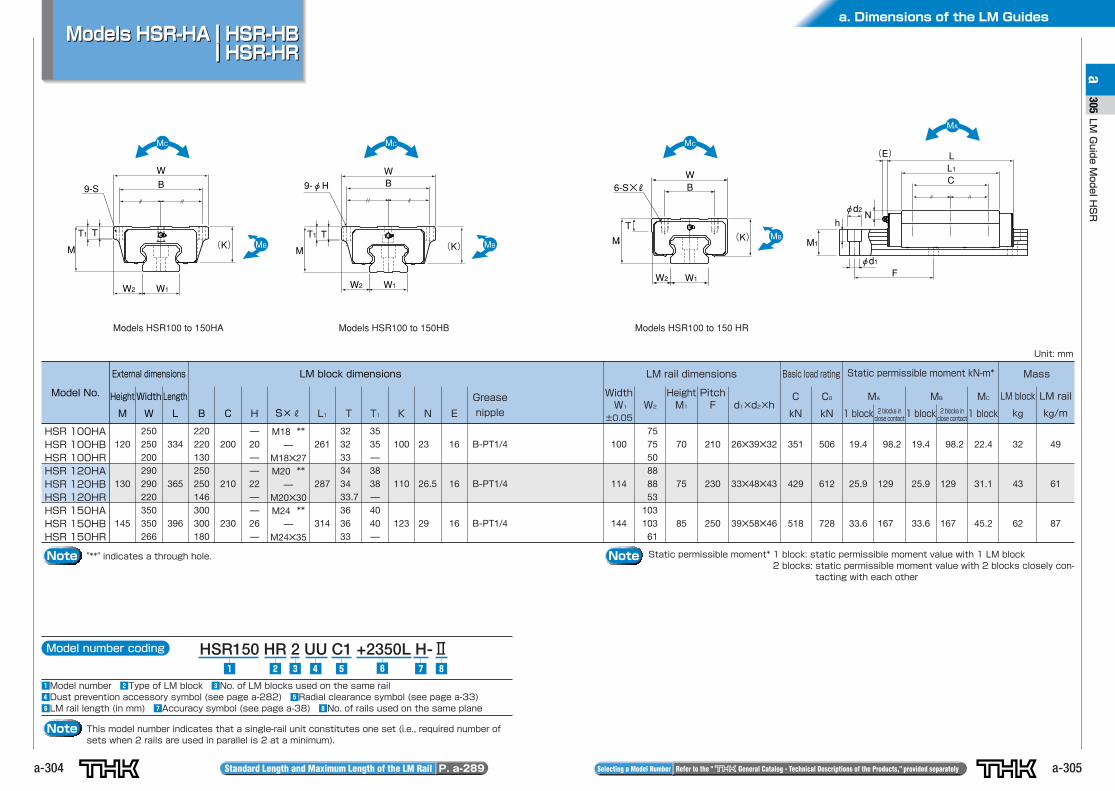
Models HSR-HA HSR-HBHSR-HR
Models HSR-HA HSR-HBHSR-HR
W2 W1
WB
M
TT1
9-S
W2 W1
WB9-φH
(K) M
TT1(K)
φd1
φd2
F
Nh
M1
(E)
L1L
C
W2 W1
W
M
T
B6-S×R
(K)
Model number coding HSR150 HR 2 UU C1 +2350L H-Ⅱ
zModel number xType of LM block cNo. of LM blocks used on the same railvDust prevention accessory symbol (see page a-282) bRadial clearance symbol (see page a-33)nLM rail length (in mm) mAccuracy symbol (see page a-38) ,No. of rails used on the same plane
z ,v b n mcx
Note This model number indicates that a single-rail unit constitutes one set (i.e., required number ofsets when 2 rails are used in parallel is 2 at a minimum).
Standard Length and Maximum Length of the LM Rail P. a-289 Selecting a Model Number Refer to the " General Catalog - Technical Descriptions of the Products," provided separately
Model No.
External dimensions LM block dimensions
Height
M
Width
W
Length
L B C S×R L1 T T1 K N E
Grease
nipple
WidthW1
±0.05
LM rail dimensions Basic load rating Static permissible moment kN-m* Mass
W2
HeightM1
PitchF d1×d2×h
C0
kN
C
kN
LM block
kg
LM rail
kg/m
HSR 100HAHSR 100HBHSR 100HRHSR 120HAHSR 120HBHSR 120HRHSR 150HAHSR 150HBHSR 150HR
120
130
145
250250200290290220350350266
334
365
396
220220130250250146300300180
200
210
230
H
—20——22——26—
M18 **—
M18✕27M20 **
—M20✕30M24 **
—M24✕35
261
287
314
323233343433.7363633
3535—3838—4040—
100
110
123
23
26.5
29
16
16
16
B-PT1/4
B-PT1/4
B-PT1/4
100
114
144
757550888853
10310361
70
75
85
210
230
250
26✕39✕32
33✕48✕43
39✕58✕46
351
429
518
506
612
728
19.4
25.9
33.6
98.2
129
167
19.4
25.9
33.6
22.4
31.1
45.2
98.2
129
167
32
43
62
49
61
87
Unit: mm
Note "**" indicates a through hole.
MA
1 block
MB
1 block
MC
1 block
Models HSR100 to 150HA Models HSR100 to 150HB Models HSR100 to 150 HR
Note Static permissible moment* 1 block: static permissible moment value with 1 LM block2 blocks: static permissible moment value with 2 blocks closely con-
tacting with each other
2 blocks inclose contact
2 blocks inclose contact
a-306
Model No.
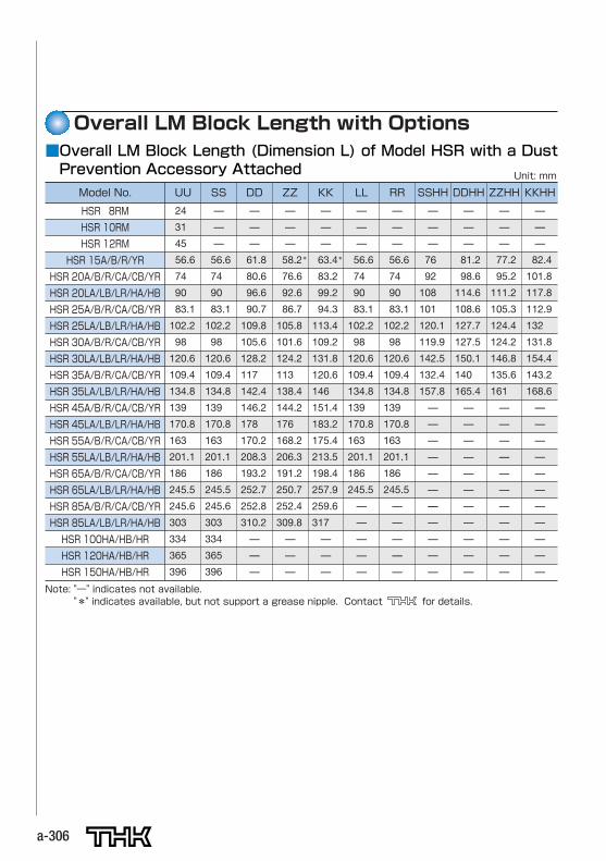
HSR 8RM
HSR 10RM
HSR 12RM
HSR 15A/B/R/YR
HSR 20A/B/R/CA/CB/YR
HSR 20LA/LB/LR/HA/HB
HSR 25A/B/R/CA/CB/YR
HSR 25LA/LB/LR/HA/HB
HSR 30A/B/R/CA/CB/YR
HSR 30LA/LB/LR/HA/HB
HSR 35A/B/R/CA/CB/YR
HSR 35LA/LB/LR/HA/HB
HSR 45A/B/R/CA/CB/YR
HSR 45LA/LB/LR/HA/HB
HSR 55A/B/R/CA/CB/YR
HSR 55LA/LB/LR/HA/HB
HSR 65A/B/R/CA/CB/YR
HSR 65LA/LB/LR/HA/HB
HSR 85A/B/R/CA/CB/YR
HSR 85LA/LB/LR/HA/HB
HSR 100HA/HB/HR
HSR 120HA/HB/HR
HSR 150HA/HB/HR
UU SS DD ZZ KK LL RR SSHH DDHH ZZHH KKHH
Overall LM Block Length with Options■Overall LM Block Length (Dimension L) of Model HSR with a DustPrevention Accessory Attached Unit: mm
24
31
45
56.6
74
90
83.1
102.2
98
120.6
109.4
134.8
139
170.8
163
201.1
186
245.5
245.6
303
334
365
396
—
—
—
56.6
74
90
83.1
102.2
98
120.6
109.4
134.8
139
170.8
163
201.1
186
245.5
245.6
303
334
365
396
—
—
—
61.8
80.6
96.6
90.7
109.8
105.6
128.2
117
142.4
146.2
178
170.2
208.3
193.2
252.7
252.8
310.2
—
—
—
—
—
—
58.2*
76.6
92.6
86.7
105.8
101.6
124.2
113
138.4
144.2
176
168.2
206.3
191.2
250.7
252.4
309.8
—
—
—
—
—
—
63.4*
83.2
99.2
94.3
113.4
109.2
131.8
120.6
146
151.4
183.2
175.4
213.5
198.4
257.9
259.6
317
—
—
—
—
—
—
56.6
74
90
83.1
102.2
98
120.6
109.4
134.8
139
170.8
163
201.1
186
245.5
—
—
—
—
—
—
—
—
56.6
74
90
83.1
102.2
98
120.6
109.4
134.8
139
170.8
163
201.1
186
245.5
—
—
—
—
—
—
—
—
76
92
108
101
120.1
119.9
142.5
132.4
157.8
—
—
—
—
—
—
—
—
—
—
—
—
—
—
81.2
98.6
114.6
108.6
127.7
127.5
150.1
140
165.4
—
—
—
—
—
—
—
—
—
—
—
—
—
—
77.2
95.2
111.2
105.3
124.4
124.2
146.8
135.6
161
—
—
—
—
—
—
—
—
—
—
—
—
—
—
82.4
101.8
117.8
112.9
132
131.8
154.4
143.2
168.6
—
—
—
—
—
—
—
—
—
—
—
Note: "—" indicates not available."*" indicates available, but not support a grease nipple. Contact for details.
a. Dimensions of the LM Guides
a-307
LMGuideModelHSR
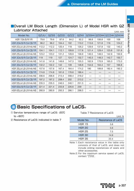
a307■Overall LM Block Length (Dimension L) of Model HSR with QZ
Lubricator Attached
Model No.
HSR 15A/B/R/YR
HSR 20A/B/R/CA/CB/YR
HSR 20LA/LB/LR/HA/HB
HSR 25A/B/R/CA/CB/YR
HSR 25LA/LB/LR/HA/HB
HSR 30A/B/R/CA/CB/YR
HSR 30LA/LB/LR/HA/HB
HSR 35A/B/R/CA/CB/YR
HSR 35LA/LB/LR/HA/HB
HSR 45A/B/R/CA/CB/YR
HSR 45LA/LB/LR/HA/HB
HSR 55A/B/R/CA/CB/YR
HSR 55LA/LB/LR/HA/HB
HSR 65A/B/R/CA/CB/YR
HSR 65LA/LB/LR/HA/HB
QZUU
Unit: mm
79.6
96.2
112.2
104.1
123.2
119
141.6
132.2
157.6
174.8
206.6
197.2
235.3
221.4
280.9
QZSS
79.6
96.2
112.2
104.1
123.2
119
141.6
132.2
157.6
174.8
206.6
197.2
235.3
221.4
280.9
QZDD
87.6
104.4
120.4
112.1
131.2
127
149.6
142
167.4
181.6
213.4
208.4
246.5
233.8
293.3
QZZZ
84.2
102
118
109.8
128.9
124.7
147.3
139
164.4
176.6
208.4
202
240.1
226.6
286.1
QZKK
92.2
110.2
126.2
117.8
136.9
132.7
155.3
148.8
174.2
186.4
218.2
213.2
251.3
239
298.5
QZSSHH
98.8
113.6
129.6
121.4
140.5
140.3
162.9
154.6
180
—
—
—
—
—
—
QZDDHH
106.8
121.8
137.8
129.4
148.5
148.3
170.9
164.4
189.8
—
—
—
—
—
—
QZZZHH
100
116
132
123.8
142.9
142.7
165.3
157
182.4
—
—
—
—
—
—
QZKKHH
108
124.2
140.2
131.8
150.9
150.7
173.3
166.8
192.2
—
—
—
—
—
—
Basic Specifications of LaCS®
① Service temperature range of LaCS: -20℃
to +80℃
② Resistance of LaCS: indicated in table 7
Table 7 Resistance of LaCS
Model No.
HSR 15
HSR 20
HSR 25
HSR 30
HSR 35
Resistance of LaCS
3.8
5.6
7.5
14.9
22.4
Unit: N
Note 1: Each resistance value in the table onlyconsists of that of LaCS, and does notinclude sliding resistances of seals andother accessories.
Note 2: For the maximum service speed of LaCS,contact .
a-308
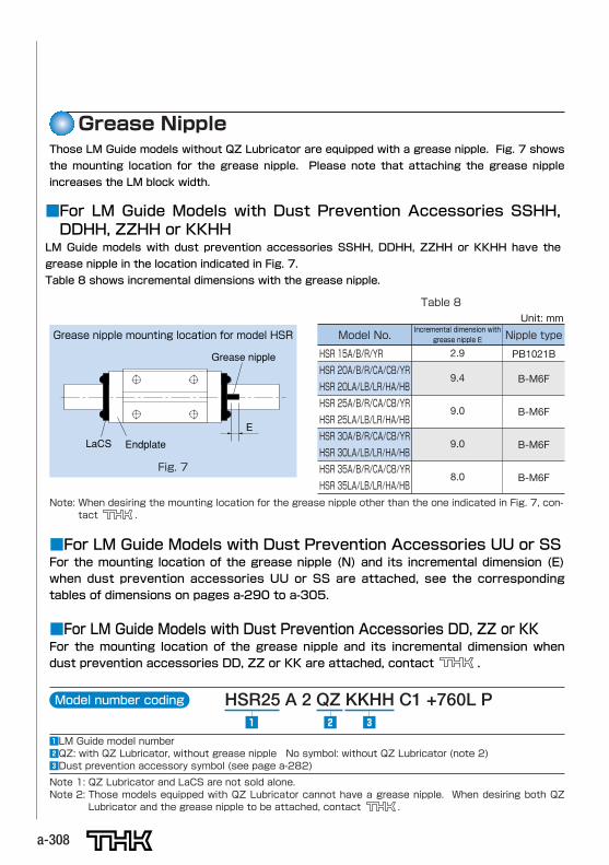
Grease Nipple
■For LM Guide Models with Dust Prevention Accessories SSHH,DDHH, ZZHH or KKHH
LM Guide models with dust prevention accessories SSHH, DDHH, ZZHH or KKHH have the
grease nipple in the location indicated in Fig. 7.
Table 8 shows incremental dimensions with the grease nipple.
Those LM Guide models without QZ Lubricator are equipped with a grease nipple. Fig. 7 shows
the mounting location for the grease nipple. Please note that attaching the grease nipple
increases the LM block width.
Grease nipple
LaCS Endplate
E
Fig. 7
Grease nipple mounting location for model HSRIncremental dimension with
grease nipple E
2.9
9.4
9.0
9.0
8.0
Nipple type
PB1021B
B-M6F
B-M6F
B-M6F
B-M6F
Note: When desiring the mounting location for the grease nipple other than the one indicated in Fig. 7, con-tact .
Model number coding HSR25 A 2 QZ KKHH C1 +760L P
zLM Guide model number xQZ: with QZ Lubricator, without grease nipple No symbol: without QZ Lubricator (note 2)cDust prevention accessory symbol (see page a-282)
z cx
Note 1: QZ Lubricator and LaCS are not sold alone.Note 2: Those models equipped with QZ Lubricator cannot have a grease nipple. When desiring both QZ
Lubricator and the grease nipple to be attached, contact .
Table 8Unit: mm
■For LM Guide Models with Dust Prevention Accessories UU or SSFor the mounting location of the grease nipple (N) and its incremental dimension (E)when dust prevention accessories UU or SS are attached, see the correspondingtables of dimensions on pages a-290 to a-305.
■For LM Guide Models with Dust Prevention Accessories DD, ZZ or KKFor the mounting location of the grease nipple and its incremental dimension whendust prevention accessories DD, ZZ or KK are attached, contact .
Model No.
HSR 15A/B/R/YR
HSR 20A/B/R/CA/CB/YR
HSR 20LA/LB/LR/HA/HB
HSR 25A/B/R/CA/CB/YR
HSR 25LA/LB/LR/HA/HB
HSR 30A/B/R/CA/CB/YR
HSR 30LA/LB/LR/HA/HB
HSR 35A/B/R/CA/CB/YR
HSR 35LA/LB/LR/HA/HB
a. Dimensions of the LM Guides
a-309
LMGuideModelHSR
a309
■Laminated Contact Scraper LaCS for LM GuidesService environment●Be sure the service temperature range of Laminated Contact Scraper LaCS is between -20℃
and +80℃, and do not clean LaCS in an organic solvent or white kerosene, or leave it
unpacked.
Impregnating oil●The lubricant impregnated into Laminated Contact Scraper LaCS is used to increase the slid-
ing capability of LaCS itself. For lubrication of the LM Guide, attach QZ Lubricator or the
grease nipple.
Function●The intended role of Laminated Contact Scraper LaCS is to remove foreign matter or liquids.
To seal oils, end seals are needed.
Design●When using Laminated Contact Scraper LaCS, be sure to use the dedicated cap C for LM rail
mounting holes or an appropriate form of cover.
■QZ Lubricator for LM GuidesHandling●Dropping or hitting this product may damage it. Take much care when handling it.
●Do not clean it with an organic solvent or white kerosene.
●Do not leave it unpacked for a long period of time.
●Do not block the air vent with grease or the like.
Service temperature range●Be sure the service temperature of this product is between -10℃ and +50℃. When using it
beyond the service temperature range, contact .
Use in a special environment●When using it in a special environment, contact .
Precaution on selection●Be sure the stroke is longer than the overall length of the LM block length attached with QZ
Lubricator.
Corrosion prevention of LM Guides●QZ Lubricator is a lubricating device designed to feed a minimum amount of oil to the ball
raceway of LM rails, and does not provide corrosion prevention to the whole LM Guide. When
using it in an environment subject to a coolant or the like, we strongly recommend applying
grease or other anti-corrosion agent to the mounting base surface and the LM rail end sur-
faces of the LM Guide as an anti-corrosion measure.
Precautions on Use