Embed Size (px)
Citation preview
LNG heat exchangers
TEP-10
2008
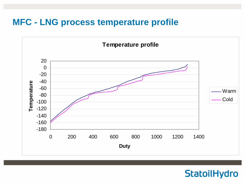
MFC - LNG process temperature profile
Temperature profile
-180-160-140-120-100-80-60-40-20
020
0 200 400 600 800 1000 1200 1400
Duty
Tem
pera
ture
WarmCold
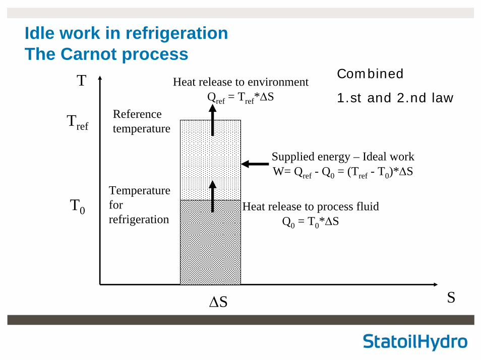
Idle work in refrigerationThe Carnot process
T
Tref
S
T0
ΔS
Temperaturefor refrigeration
Heat release to environmentQref = Tref*ΔS
Referencetemperature
Heat release to process fluidQ0 = T0*ΔS
Supplied energy – Ideal workW= Qref - Q0 = (Tref - T0)*ΔS
Combined
1.st and 2.nd law
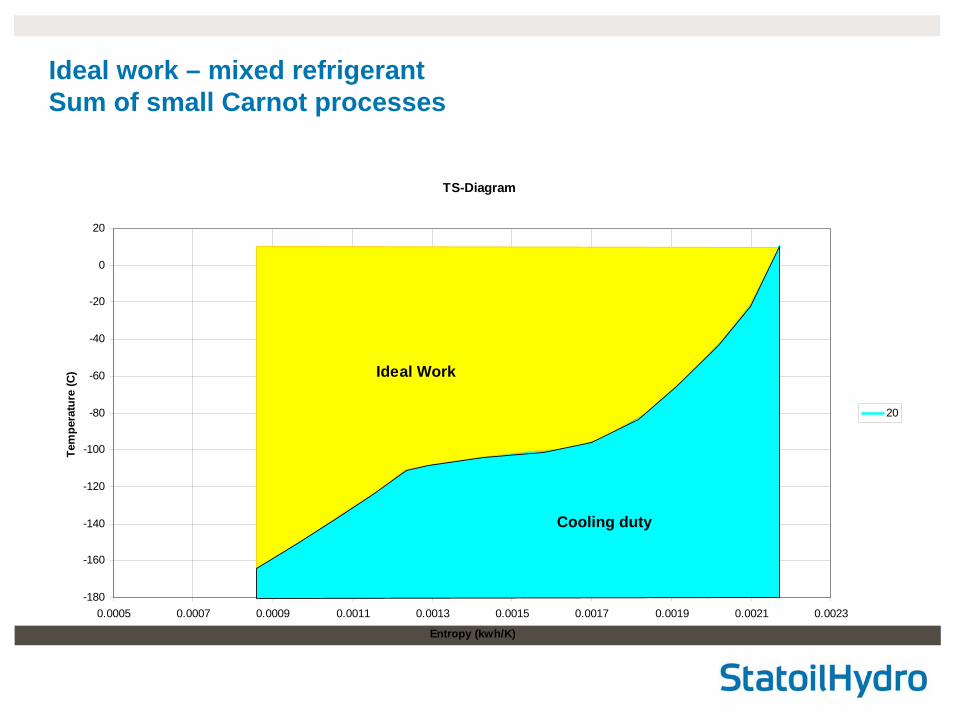
Ideal work – mixed refrigerantSum of small Carnot processes
TS-Diagram
-180
-160
-140
-120
-100
-80
-60
-40
-20
0
20
0.0005 0.0007 0.0009 0.0011 0.0013 0.0015 0.0017 0.0019 0.0021 0.0023
Entropy (kwh/K)
Tem
pera
ture
(C)
20
Ideal Work
Cooling duty
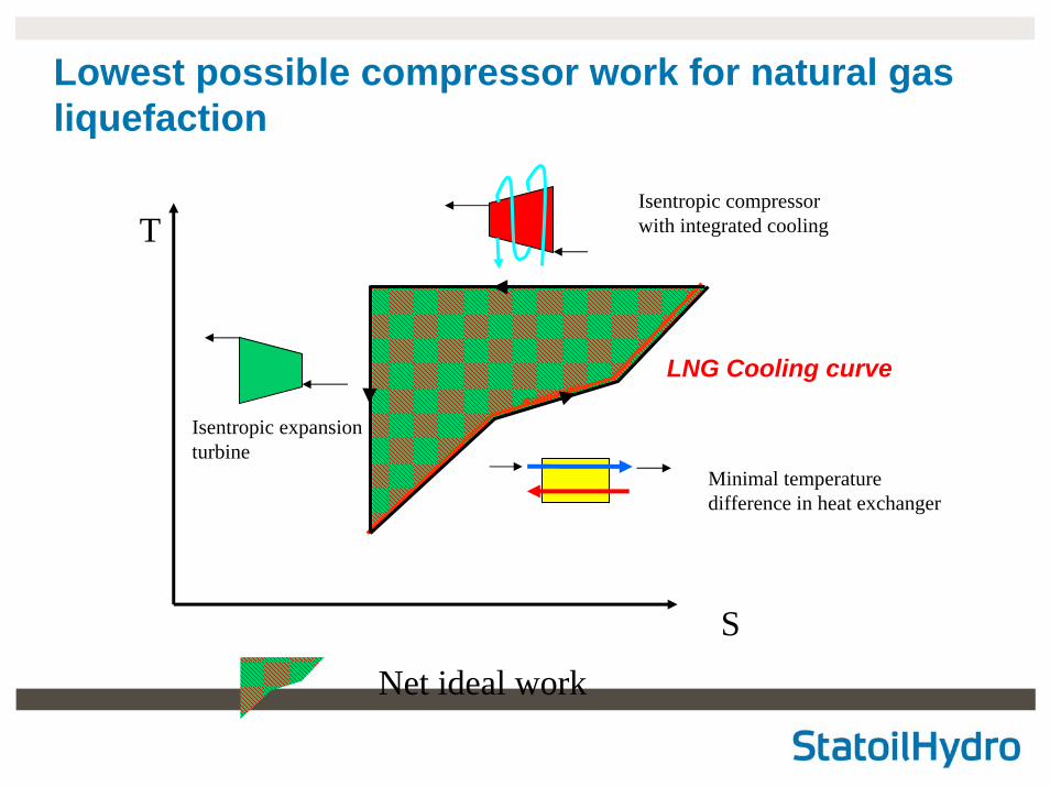
T
S
Net ideal work
LNG Cooling curve
Isentropic compressor with integrated cooling
Lowest possible compressor work for natural gas liquefaction
Isentropic expansion turbine
Minimal temperaturedifference in heat exchanger
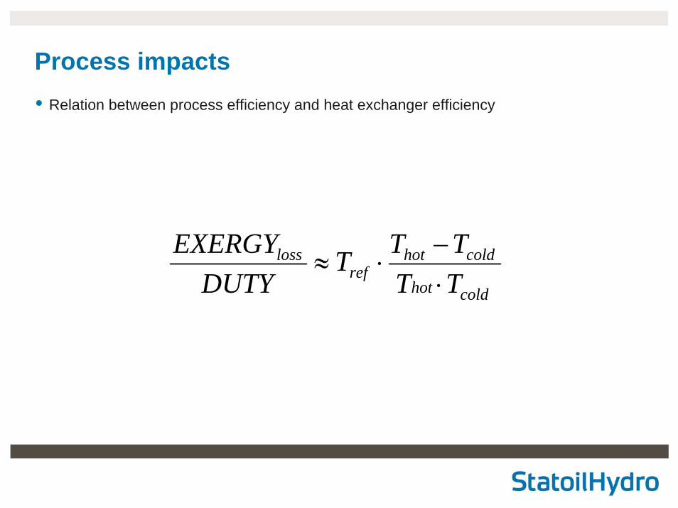
Process impacts• Relation between process efficiency and heat exchanger efficiency
coldhot
coldhotref
loss
TTTTT
DUTYEXERGY
⋅−
⋅≈
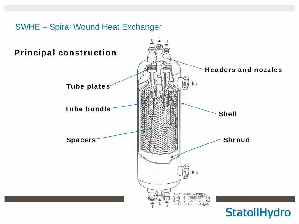
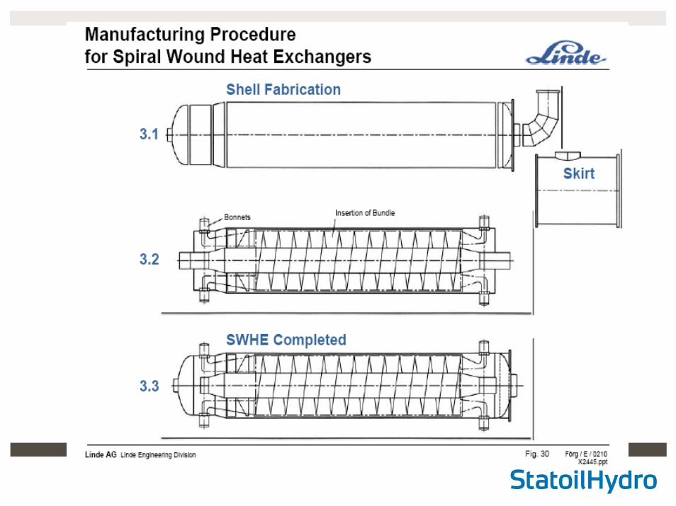
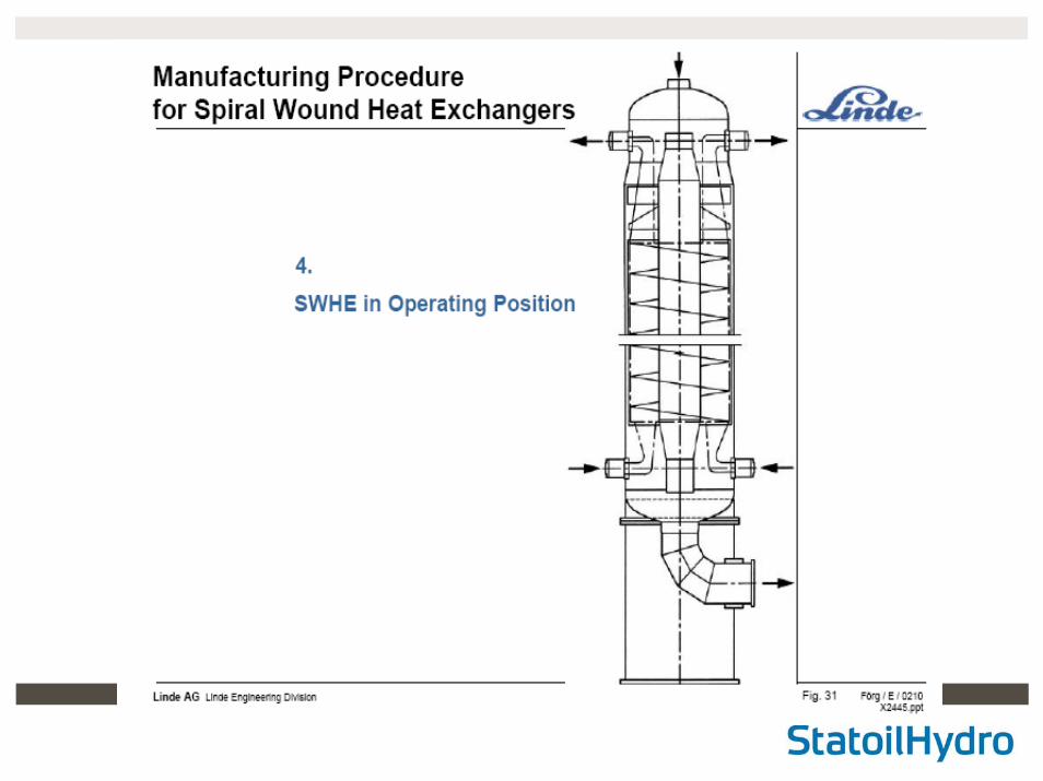
SWHE – Spiral Wound Heat Exchanger
Principal construction
Tube bundle
Tube plates
Headers and nozzles
Spacers Shroud
Shell
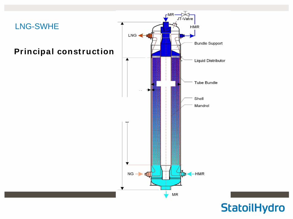
LNG-SWHE
Principal construction
LNG02 PRE
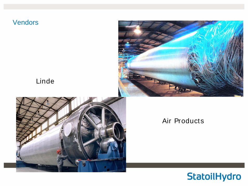
Vendors
Linde
Air Products
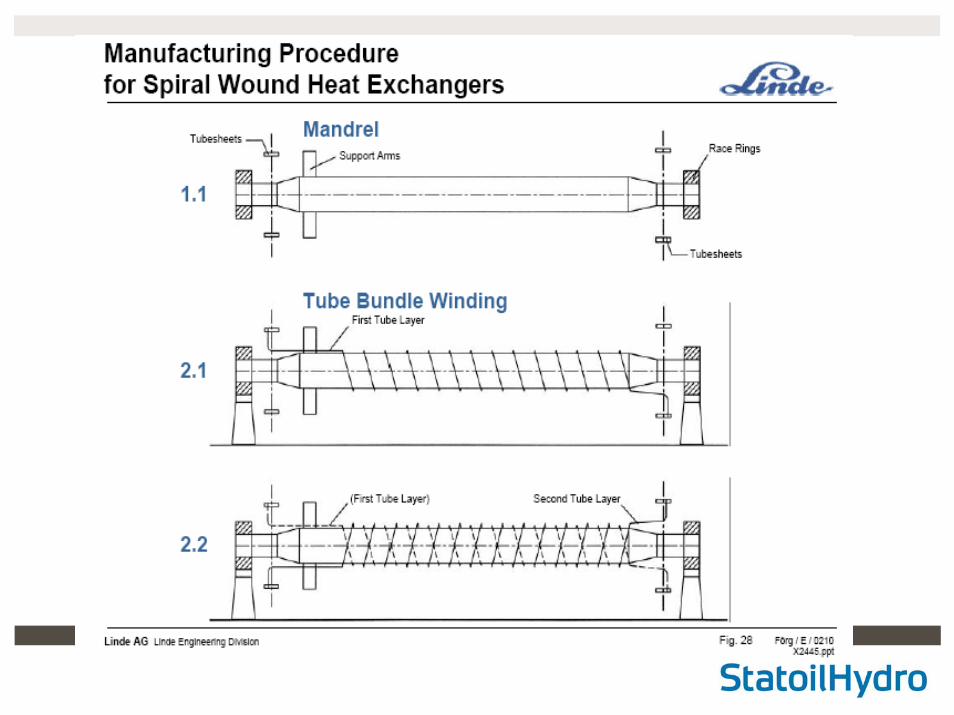
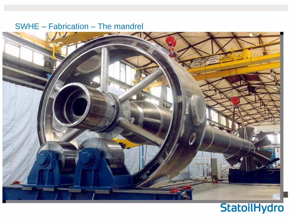
SWHE – Fabrication – The mandrel
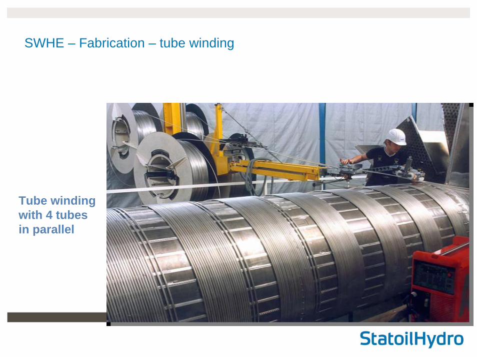
Tube windingwith 4 tubesin parallel
SWHE – Fabrication – tube winding
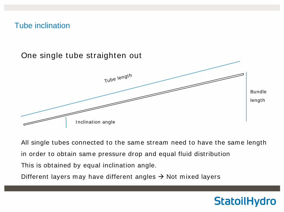
Tube inclination
Bundle
length
Tube length
Inclination angle
One single tube straighten out
All single tubes connected to the same stream need to have the same length
in order to obtain same pressure drop and equal fluid distribution
This is obtained by equal inclination angle.
Different layers may have different angles Not mixed layers
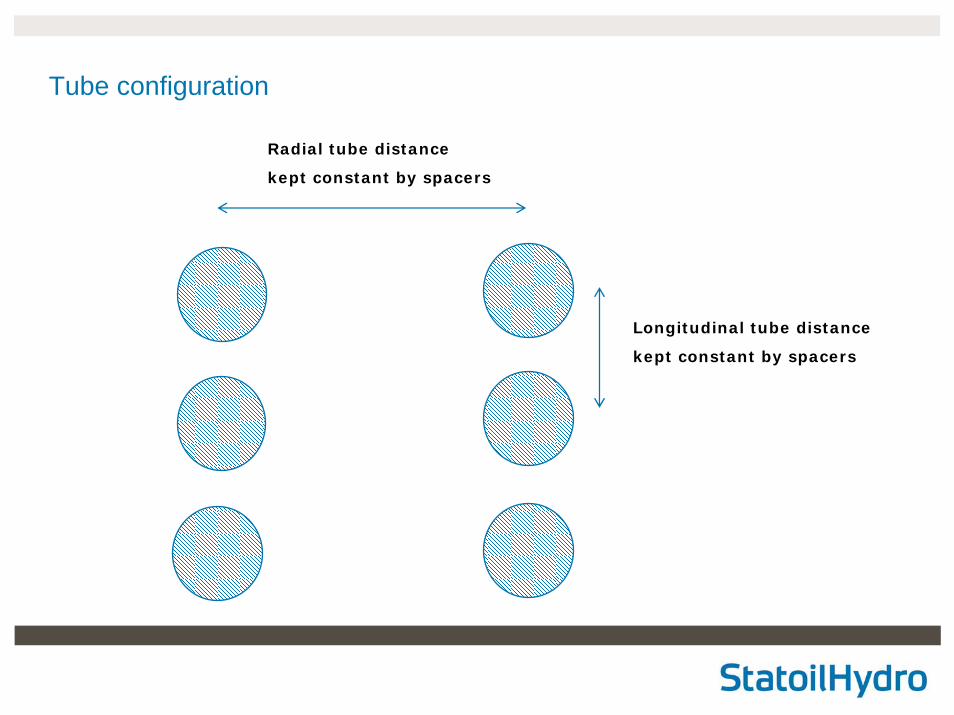
Tube configuration
Radial tube distance
kept constant by spacers
Longitudinal tube distance
kept constant by spacers
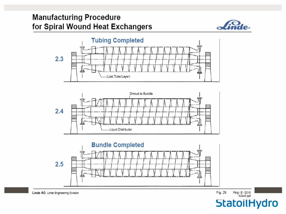
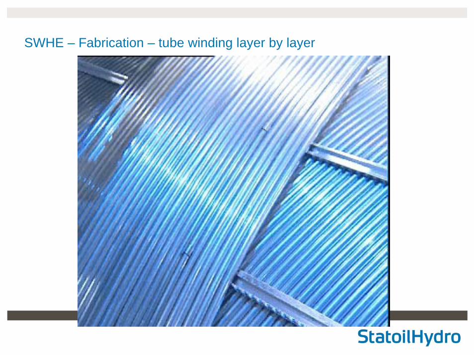
SWHE – Fabrication – tube winding layer by layer
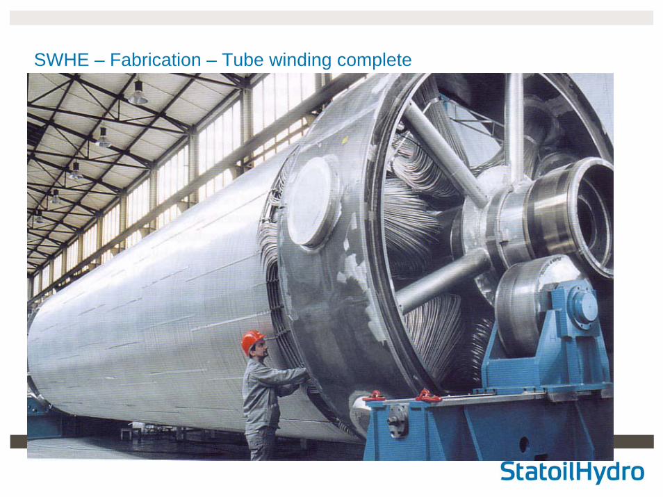
SWHE – Fabrication – Tube winding complete
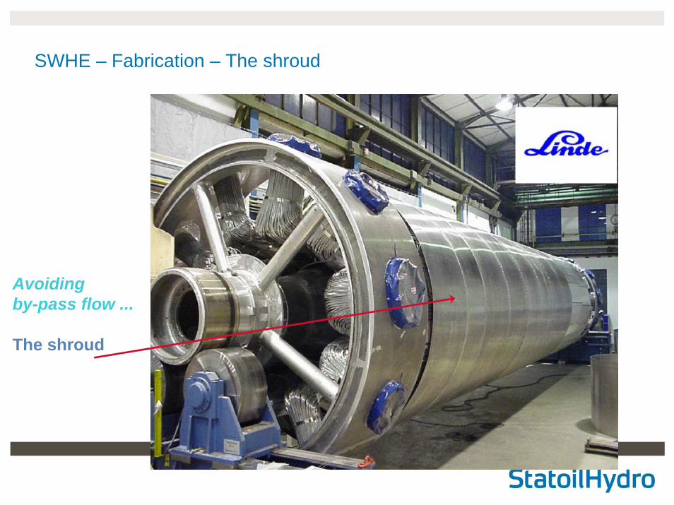
SWHE – Fabrication – The shroud
Avoidingby-pass flow ...
The shroud
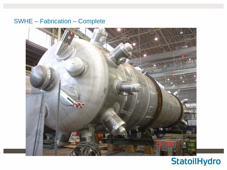
SWHE – Fabrication – Complete
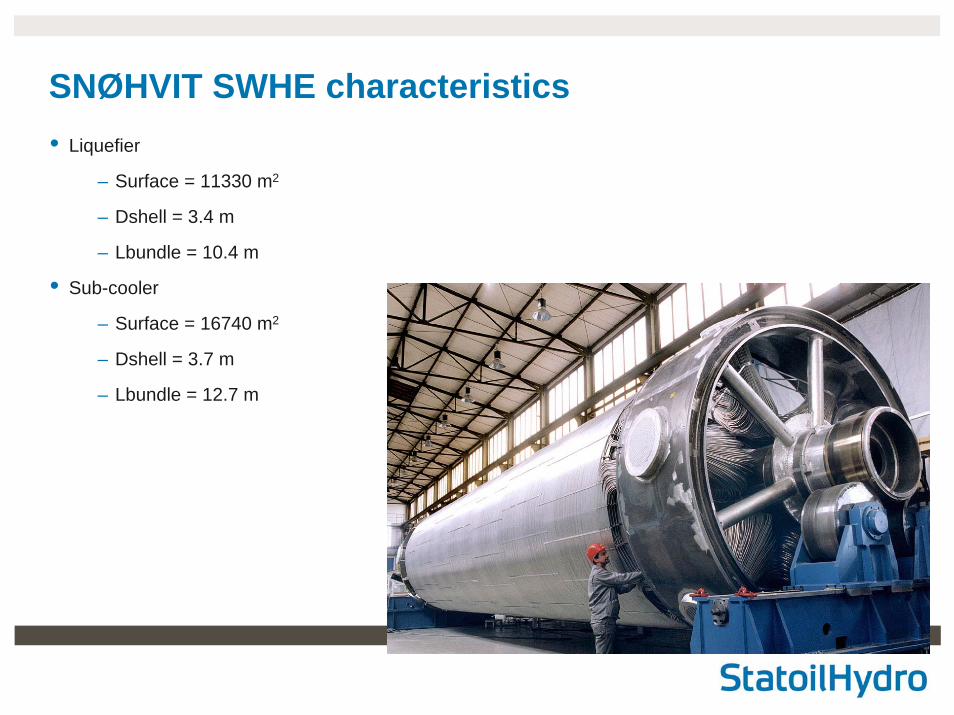
SNØHVIT SWHE characteristics• Liquefier
– Surface = 11330 m2
– Dshell = 3.4 m
– Lbundle = 10.4 m
• Sub-cooler
– Surface = 16740 m2
– Dshell = 3.7 m
– Lbundle = 12.7 m
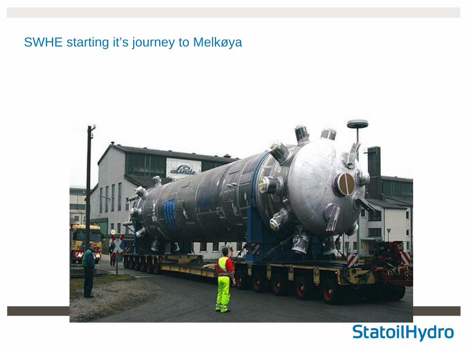
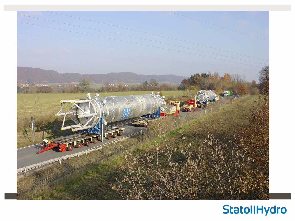
SWHE starting it’s journey to Melkøya
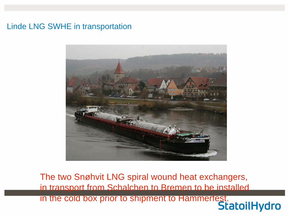
The two Snøhvit LNG spiral wound heat exchangers, in transport from Schalchen to Bremen to be installed in the cold box prior to shipment to Hammerfest.
Linde LNG SWHE in transportation
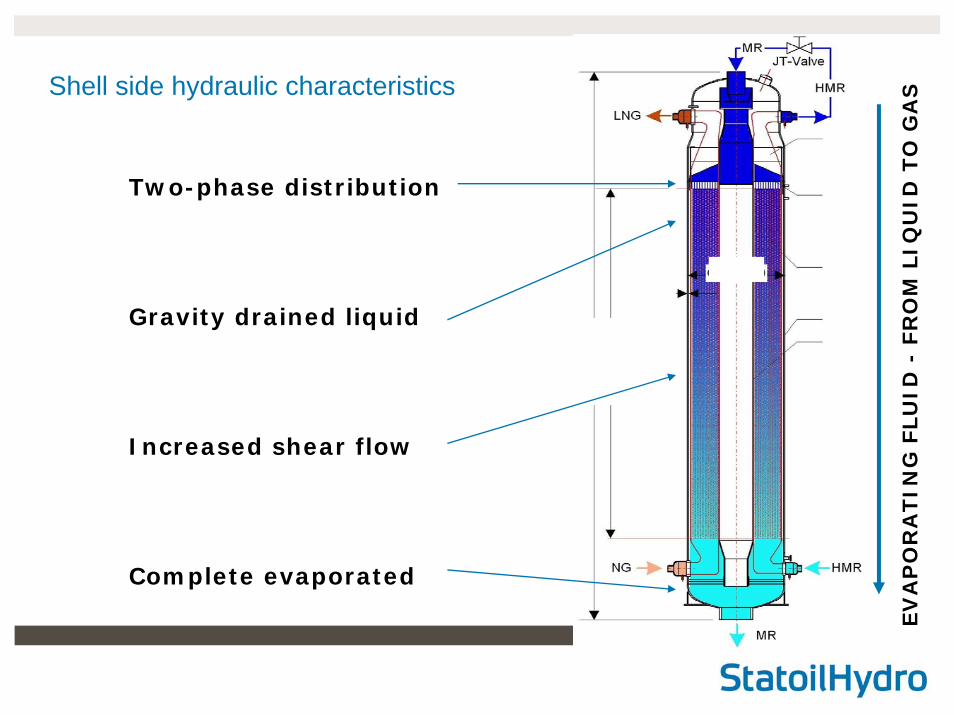
Shell side hydraulic characteristics
Two-phase distribution
Gravity drained liquid
Increased shear flow
Complete evaporated
EV
AP
OR
ATIN
G F
LU
ID -
FR
OM
LIQ
UID
TO
GA
S
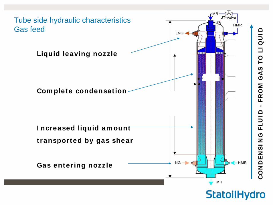
Tube side hydraulic characteristicsGas feed
Liquid leaving nozzle
Complete condensation
Increased liquid amount
transported by gas shear
Gas entering nozzle
CO
ND
EN
SIN
G F
LU
ID -
FR
OM
GA
S T
O L
IQU
ID
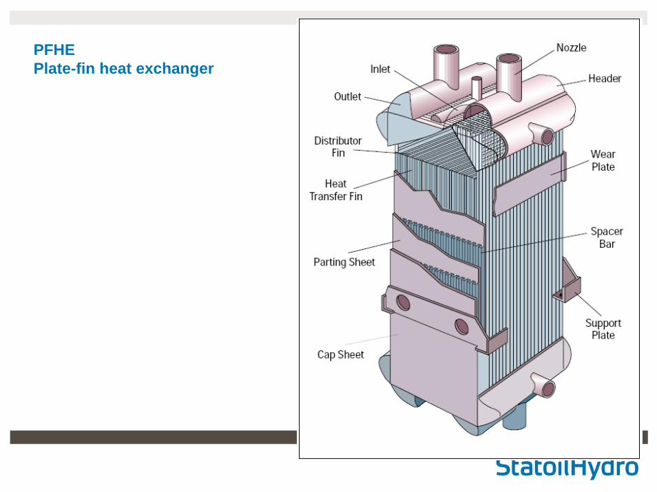
PFHE Plate-fin heat exchanger
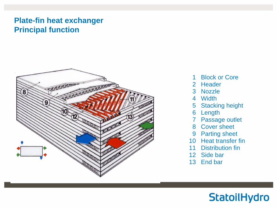
123456789
10111213
Block or CoreHeaderNozzleWidthStacking heightLengthPassage outletCover sheetParting sheetHeat transfer finDistribution finSide barEnd bar
Plate-fin heat exchangerPrincipal function
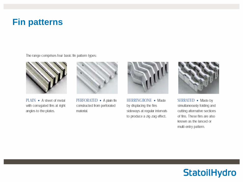
Fin patterns
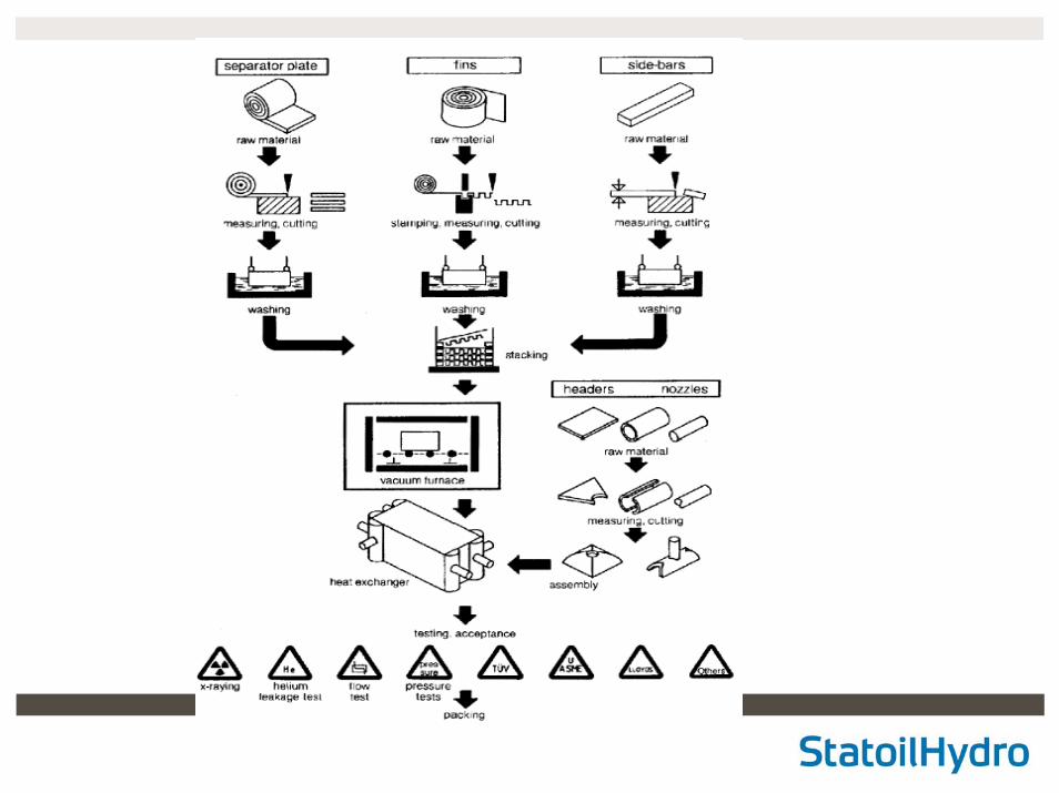
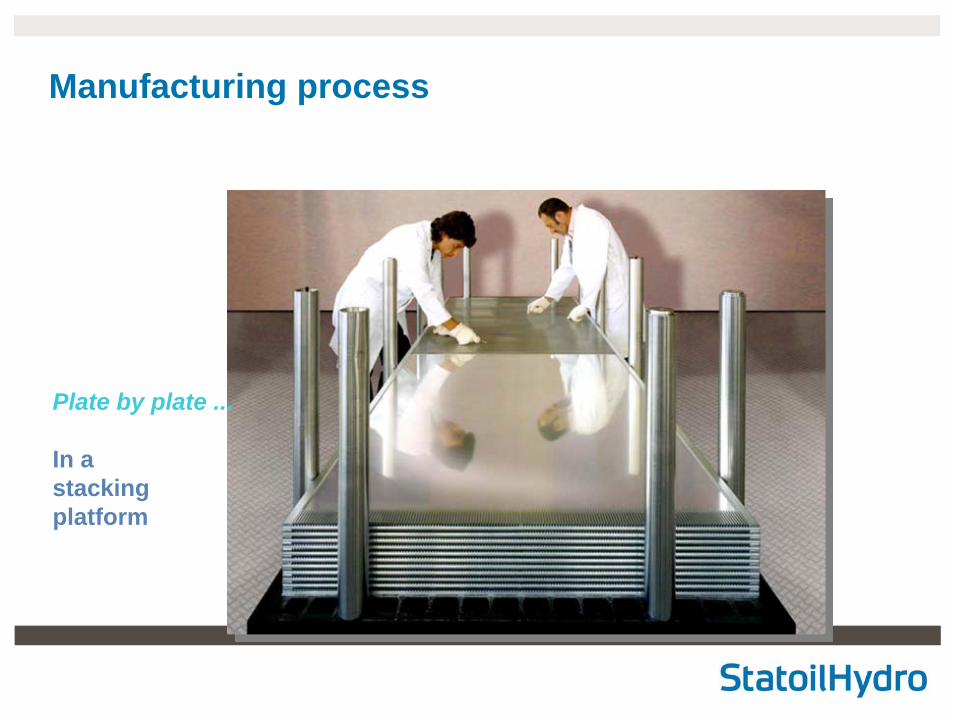
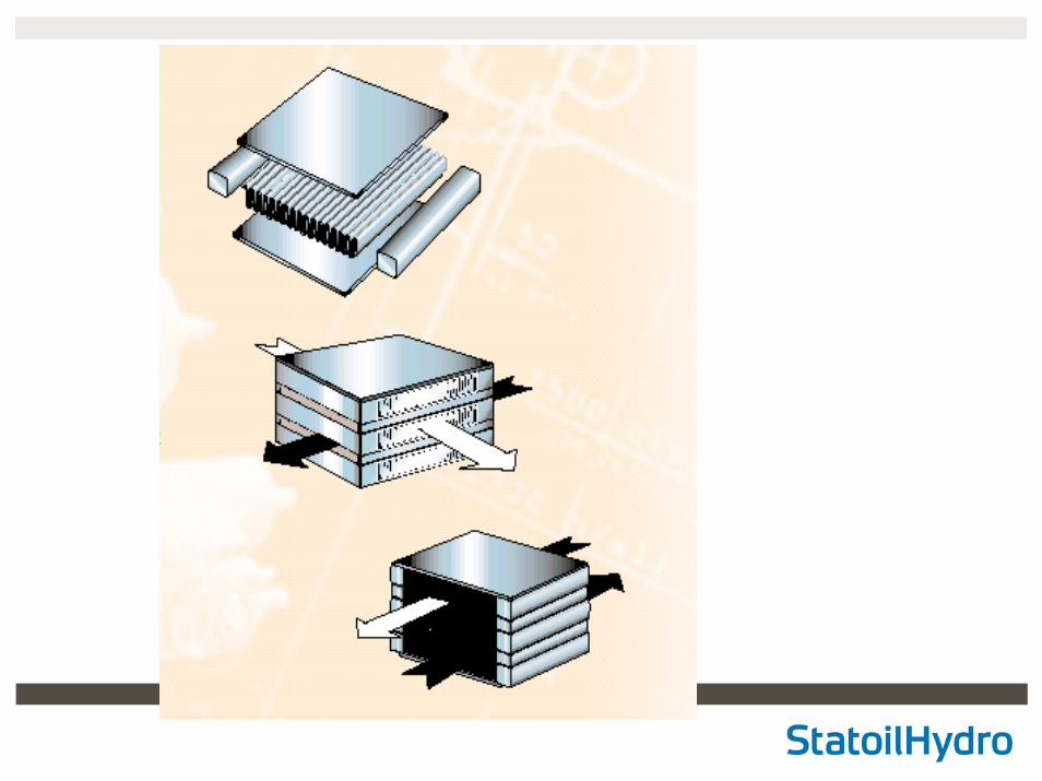
Plate by plate ...
In a stackingplatform
Manufacturing process
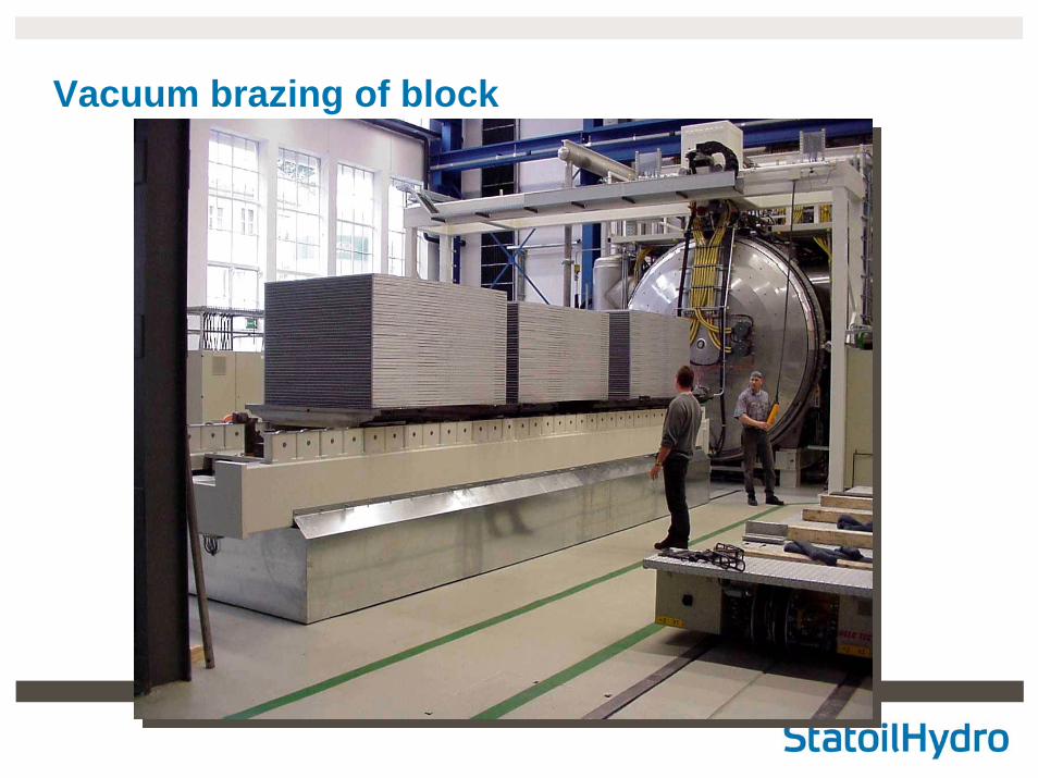
Vacuum brazing of block
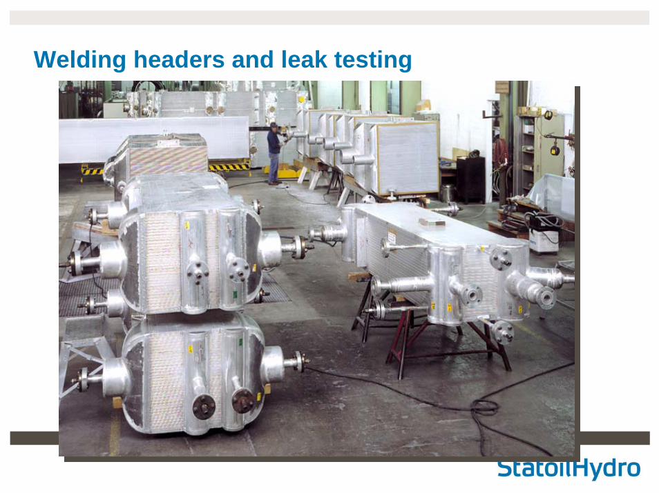
Welding headers and leak testing
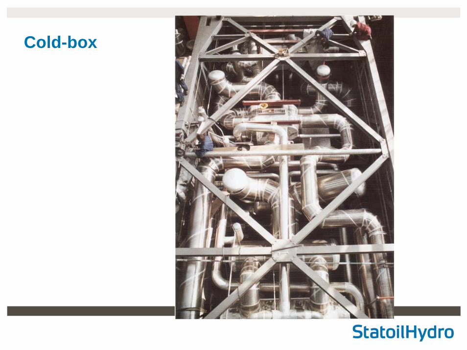
Cold-box
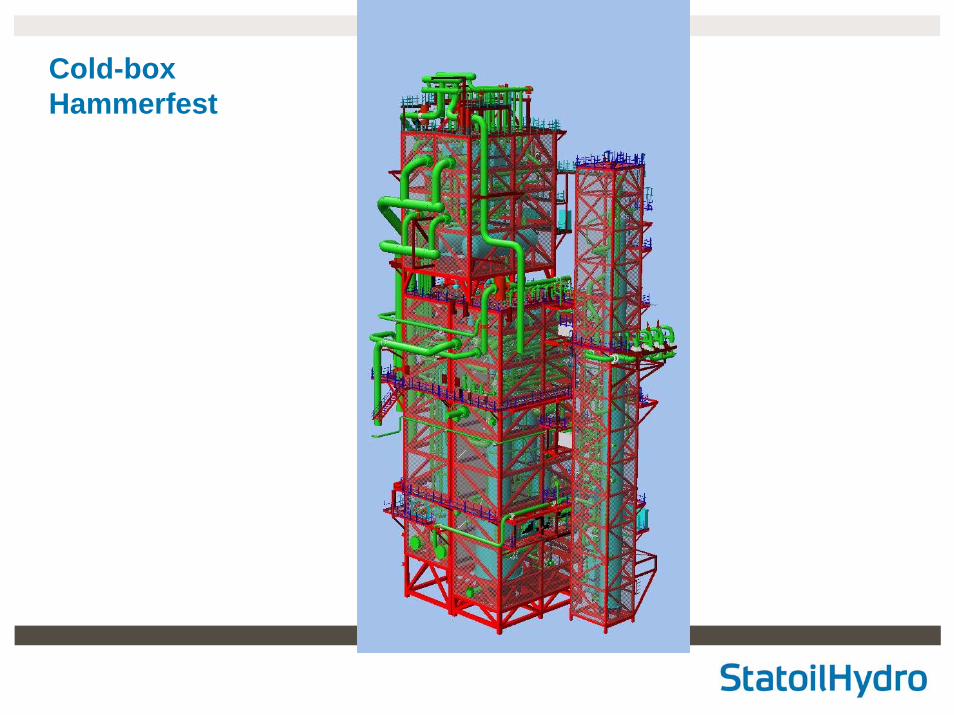
Cold-boxHammerfest
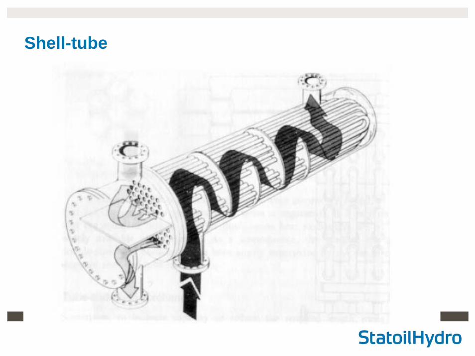
Shell-tube
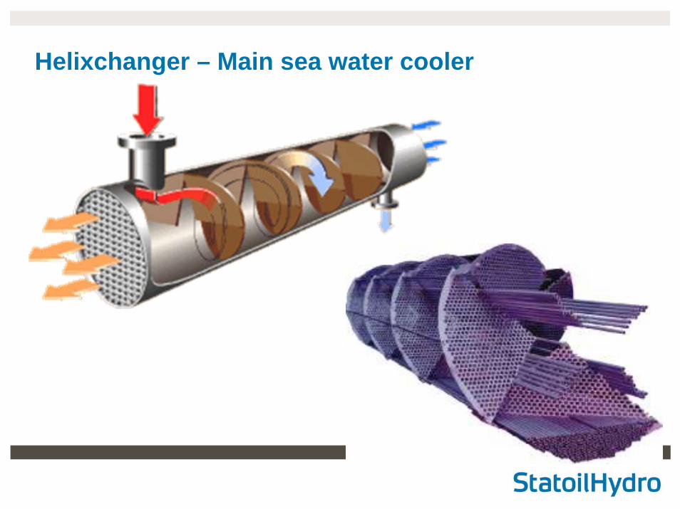
Helixchanger – Main sea water cooler
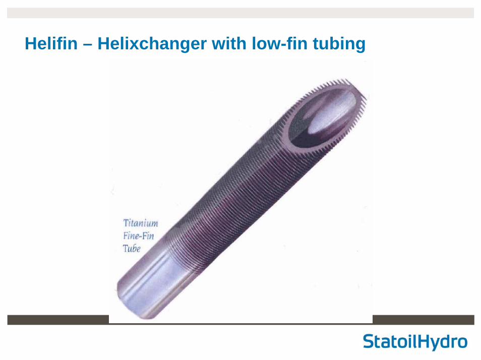
Helifin – Helixchanger with low-fin tubing
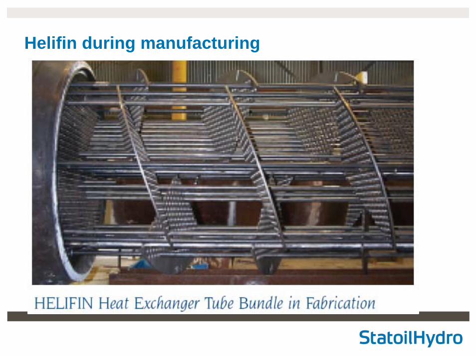
Helifin during manufacturing