Embed Size (px)
Citation preview

1
TAKENAKA TECHNICAL RESEARCH REPORT No.71 2015竹中技術研究報告 No.71 2015
Load-Settlement Behavior of Piles in Piled Raft System Based on Field Monitoring実測に基づくパイルド・ラフト基礎中の群杭の荷重-沈下挙動
Kiyoshi Yamashita 山下 清*1 Shuichi Wakai 若井 修一*2 Junji Hamada 濱田 純次*3
SummaryLoad-settlement behavior of piles in a piled raft system supporting a twelve-story office building is discussed in comparison
with a result from pile load testing carried out at design stage. The piled raft combined with grid-form cement deep mixing
walls was employed, where the pile toe was embedded in very dense sand. Based on the comparison of load-settlement behavior
of pile group derived from field monitoring and that from the pile load test, it was found that the former curves were roughly
consistent with the latter curve when the effect of pile diameter on the pile head stiffness was considered. Namely, for a piled
raft consisting of piles embedded in thick dense sand layer with large spacing, no significant pile group effect on settlement was
found. In this case, it was found that pile load testing is quite useful in predicting long-term settlements of piled rafts.
Keywords: piled raft foundation, settlement, load sharing, pile load testing, field monitoring
梗 概本文は,パイルド・ラフト基礎中の群杭の荷重-沈下性状を調べるため,12階建て事務所ビルに
おける基礎の長期挙動観測結果と設計時に実施した杭の鉛直載荷試験結果を比較検討したものである。基礎形式は,格子状地盤改良を併用したパイルド・ラフト基礎で,杭は密な砂層に定着している。観測結果から得た群杭の荷重-沈下関係と単杭の鉛直載荷試験結果を比較した結果,杭径の違いを補正した荷重-沈下関係の観測値は載荷試験結果と類似することが判明した。結論として,パイルド・ラフト基礎に用いる杭が密な砂層に支持しかつ杭間隔が大きい場合,杭の荷重-沈下関係における群杭効果の影響は大きくないことから,杭の載荷試験がパイルド・ラフト基礎の長期的な沈下性状の予測に有用であることが判明した。キーワード:パイルド・ラフト基礎,沈下,荷重分担,載荷試験,現場観測
1 INTRODUCTION
Piled raft foundations have been used for many buildings in Japan and the settlement and the load sharing between raft and piles have been carefully investigated for the selected buildings (Yamashita et al., 2011a; Yamashita et al., 2011b). More recently, case histories on monitoring seismic soil-pile-structure interaction on actual piled rafts were perorted (Yamashita et al., 2012; Yamashita et al., 2015).
It is now well recognized that the settlement of a pile group can differ significantly from that of a single pile at the same average load level (Poulos, 2012). Therefore, it is necessary to clarify the so-called pile group effect to develop more reliable design methods which could estimate the pile group settlement more accurately. Cooke et al. (1981) reported a case history of a friction piled raft supporting 16-story apartment, where settlement of the piled raft was compared with that from vertical pile load testing of a single pile. Mandolini and Viggiani (1997) proposed a analytical method for estimating load-settlement bebavior of piled rafts considering interactions between pile group and raft based on elastic method where initial stiffness of a single pile obtained from load testing is used. However, not so many case histories exist on examining the pile group effect.
*1 Executive Manager, Research & Development Institute, Dr. Eng. 技術研究所 専門役 博士(工学) *2 Chief Researcher, Research & Development Institute 技術研究所 主任研究員*3 Chief Researcher, Research & Development Institute, Dr. Eng. 技術研究所 主任研究員 博士(工学)
2
TAKENAKA TECHNICAL RESEARCH REPORT No.71 2015竹中技術研究報告 No.71 2015
In this paper, to investigate the behavior of piles in a piled raft system as well as to examine the effectiveness of pile load tesing for designing piled rafts, load-settlement behavior of piles derived from field monitoring of a full-scale piled raft and that from load testing of a single pile are compared.
2 BUILDING AND FOUNDATION
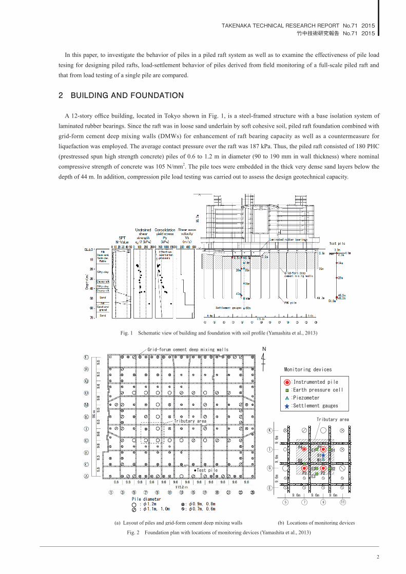
A 12-story office building, located in Tokyo shown in Fig. 1, is a steel-framed structure with a base isolation system of laminated rubber bearings. Since the raft was in loose sand underlain by soft cohesive soil, piled raft foundation combined with grid-form cement deep mixing walls (DMWs) for enhancement of raft bearing capacity as well as a countermeasure for liquefaction was employed. The average contact pressure over the raft was 187 kPa. Thus, the piled raft consisted of 180 PHC (prestressed spun high strength concrete) piles of 0.6 to 1.2 m in diameter (90 to 190 mm in wall thickness) where nominal compressive strength of concrete was 105 N/mm2. The pile toes were embedded in the thick very dense sand layers below the depth of 44 m. In addition, compression pile load testing was carried out to assess the design geotechnical capacity.
Fig. 2 Foundation plan with locations of monitoring devices (Yamashita et al., 2013)
Fig. 1 Schematic view of building and foundation with soil profile (Yamashita et al., 2013)

3
TAKENAKA TECHNICAL RESEARCH REPORT No.71 2015竹中技術研究報告 No.71 2015
The pile was constructed by inserting the precast piles into a pre-augered borehole filled with mixed-in-place soil cement for shaft and with concrete for foot protection in order to enhance the toe resistance (as shown in Fig. 9). Figure 2 shows the foundation plan with the locations of the monitoring devices. More details of this project were given in a previous paper (Yamashita et al., 2013).
3 RESULTS OF MONITORING
To confirm the validity of the foundation design, field measurements were performed on the foundation settlements, axial loads of the piles and contact pressure beneath the raft over three years after the end of the construction. A summary of the field monitoring are described in the following, which were updated from those in a previous paper (Yamashita et al., 2014).
3.1 Foundation settlementFigure 3 shows the measured vertical ground displacements
below the raft. The ground displacement at a depth of 8.5 m after the casting of raft was approximately equal to the settlement of the raft, and refers to raft settlement in this paper. The 2011 off the Pacific coast of Tohoku Earthquake hit the building site nine months before E.O.C. at which about 80 % of the total load of the structure acted on the foundation. The foundation settlement was 15.0 mm on March 1, 2011, ten days before the earthquake. After the earthquake, the foundation settlement increased by 0.8 mm from the pre-earthquake value to 15.8 mm on March 16, 2011. Considering the increase in settlement due to the increase in the construction load during March 1 to March 11, no significant change in foundation settlement was observed after the earthquake. The foundation set t lement increased considerably just before E.O.C. due to the water pouring into the underground pits. Thereafter, the settlement became stable and reached 21 mm 46 months after E.O.C. (August 7, 2015).
3.2 Pile load and contact pressures Figure 4 shows the development of the measured axial loads
of Piles P1-P4 versus time. The axial loads increased only slightly after E.O.C., and were stable in a same way as the raft settlement. It is interesting to note that the pile-head loads of Piles P1, P2 and P3 decreased very slightly after the 2011 earthquake, while that of Pile P4 increased a little. Figure 5 shows the measured axial loads along Pile P1 versus time. The average shaft friction between the depths of 8.5 and 20.0 m was quite small, less than 24 kPa. The shaft friction between the depths of 20.0 and 47.0 m was 82 to 88 kPa. In Pile P1, about 80% of the pile head load was carried by the shaft friction after E.O.C.
Figure 6 shows the development of the measured contact pressure between the raft and the soil and that between the raft and
Fig. 3 Measured vertical ground displacements below raft
Fig. 4 Measured pile head axial loads
Fig. 5 Measured axial loads of Pile P1
Fig. 6 Measured contact pressure and porewater pressure

4
TAKENAKA TECHNICAL RESEARCH REPORT No.71 2015竹中技術研究報告 No.71 2015
the DMWs, together with the porewater pressure beneath the raft. Meanwhile, the contact pressure between the raft and the DMWs increased markedly after the earthquake, while the contact pressure between the raft and the soil changed little. One reason for the increase in contact pressure is supposed to be improvement of “weak contact” between the contact surface of the earth pressure cell and the top surface of the DMWs due to the vertical cyclic loading from the raft during the earthquake.
3.3 Load sharing between piles and raftFigure 7 shows the time-dependent load sharing among the piles, the soil, the DMWs and the buoyancy in the tributary area
of the instrumented piles. The sum of the measured pile-head loads and the raft load area varied from 61.3 to 64.1 MN after E.O.C., so that the sum of the measured pile-head loads and the raft load was generally consistent with the design load of 64.0 MN in the tributary area. Figure 8 shows the load sharing among the piles, the DMWs and the soil in the tributary area versus time. The ratio of the load carried by the piles to the net load was estimated to be 0.72 on March 1, 2011. At that time, the ratio of the net load carried by the DMWs was estimated to be 0.07, while the ratio of the net load carried by the soil was 0.21. After the earthquake, the ratio of the load carried by the piles decreased slightly to 0.67 on March 16, 2011. The ratio of the net load carried by the soil decreased very slightly to 0.20, while the ratio of the net load carried by the DMWs increased significantly to 0.13. Thereafter, the ratio of the load carried by the piles to the net load increased slightly to 0.70 and the ratio of the net load carried by the DMWs to the effective load increased only slightly just before E.O.C., while the ratio of the net load carried by the soil decreased considerably from 0.21 to 0.17 in that term. This indicates that a small amount of load transfer from the soil to the piles occurred due to consolidation settlement of the soil.
After E.O.C., the load sharing among the piles, the DMWs and the soil was quite stable. Namely, the ratio of the effective load carried by the piles to the effective load varied from 0.69 to 0.72, and the ratio of the effective load carried by the soil to the effective load varied from 0.14 to 0.16 while that carried by the DMWs to the effective load was 0.14 to 0.15.
4 LOAD-SETTLEMENT BEHAVIOR OF PILES IN PILED RAFT SYSTEM
4.1 Pile load testingStatic pile load testing was carried out to verify the design
geotechnical capacity. Figure 9 shows the test pile together with the monitored pile P1. The test pile was 0.6 m in diameter and 48.0 m long with concrete foot protection, and installed with a pair of LVDT-type strain gauges at five depths to allow for estimation of the load distribution along the pile. The test pile was located near the south end of the foundation as shown in Fig. 2. Figure 10 shows a setup for the compression pile load test. There were four anchor piles which were located larger than 3.3 diameters from the
Fig. 7 Load sharing among piles, DMWs and soil in the tributary areaFig. 8 Load sharing of effective load among piles, DMWs and soil in
the tributary area
Fig. 9 Test pile and monitored pile P1

5
TAKENAKA TECHNICAL RESEARCH REPORT No.71 2015竹中技術研究報告 No.71 2015
test pile. The load testing was conducted 27 days after the construction of the test pile, and had five load cycles with a maximum load of 9.44 MN.
Figure 11 shows the load-settlement curves at the pile head obtained from the static pile load testing. Under the maximum load, the pile head settlement was 63.8 mm, and the estimated pile toe settlement was 12.7 mm.
4.2 Load-settlement curves of piles from monitoring and load testing
Figure 12 shows the relationship between the pile head load of the monitored piles P1-P4 and the pile head settlement, which were obtained from the data shown in Figs. 3 and 4. The pile head settlement means vertical ground displacement (measured near the instrumented piles) at the depth of 7.2 m which was extrapolated using the ground displacements at the depths of 8.5 and 14.0 m. It is seen that the pile head load increased almost linearly with the increase in pile head settlement, and pile head stiffness (pile head load devided by pile head settlement) of Piles P1-P3 (1.2 m in diameter) was significantly larger than that of Pile P4 (0.8 m in diameter), as expected. At the time of the 2011 earthquake on March 11, hysteretic load-unload vs. settlement relationship can be seen on the load-settlement data. Figure 13 shows the load-settlement data of Piles P1-P4 together with that of the test pile. To compare the load-settlement data of the monitored piles with that of the test pile, an effect of pile diameter on the pile head stiffness was considered. Namely, the load-settlement data of the monitored piles were modified by a modification factor, which means the ratio of the pile head stiffness with 0.6 m in diameter to that with 0.8 or 1.2 m in diameter. The modification factors may be calculated using an equation (1) developed by Randolph and Wroth (1978).
(1)
where P : pile-head load νs : Poisson’s ratio of soil w : pile-head settlement rm: maximum radius of influence of pile Lp : pile length ξ = GLp/Gb dp : pile diameter ρ = Gave/GLp Gave: average shear modulus of soil along pile length λ = Ep/GLp
GLp: shear modulus of soil at a depth of pile length ζ = ln(2rm/dp) Gb: shear modulus of soil below the level of pile base μLp= (Lp/dp)
The calculated modification factors as well as the properties of soil and piles are shown in Table 1. The soil shear modulus G was obtained from the shear wave velocity shown in Fig. 1, where soil nonlinearity was considered using a reduction factor
Fig. 11 Load-settlement curve at pile head from pile load testing with calculated pile head stiffness
Fig. 10 Setup for compression load test

6
TAKENAKA TECHNICAL RESEARCH REPORT No.71 2015竹中技術研究報告 No.71 2015
RG=G/G0 (G0: Soil shear modulus at small strain). To confirm the validity of the modification factors, the calculated pile head stiffness of the test pile with RG=1.0, 0.4 and 0.2 are compared with the load-settlement curve of the test pile, as shown in Fig. 11. The pile head stiffness with RG=1.0 was consistent with that at the initial loading stage, while that with RG=0.2 was roughly consistent with secant stiffness at working load of about 3 MN (one third of the maximum load).
Figure 14 compares the modified load-settlement data for Piles P1-P4 and the load-settlement curve obtained from the pile testing. The modified data were obtained by multiplying the modification factor to the pile head load of the monitored pile at the same settlement. It was found that the modified load-settlement curves were similar to that from the pile testing.
Cooke et al. (1981) reported a case history of a friction piled raft supporting 16-story apartment on London Clay, where settlement of the piled raft was compared with that from pile load test. The piled raft consisted of 351 friction piles (0.45 m in
Fig. 12 Pile head load from field monitoring vs. vertical ground displacement at depth of 7.2 m
Fig. 13 Load-settlement curves from field monitoring and pile load testing result
Fig. 14 Modified load-settlement curves and pile load testing result

7
TAKENAKA TECHNICAL RESEARCH REPORT No.71 2015竹中技術研究報告 No.71 2015
diameter and 13 m long, and the center-to-center pile spacing was 3.6 diameters). Based on the field monitoring, the settlement ratio, which is originally defined as the ratio of the flexibility of a pile in the group to that of an isolated pile (Poulos and Davis, 1980), was found to be about 9 at the building operation and increased to 16 four years after the building operation. Figure 15 shows the settlement ratio versus the pile head load. Here, the settlement ratio means the ratio of the modified load-settlement data of the monitored pile to the settlement of the test pile at the same pile head load. In contrast to the case history reported by Cooke et al. (1981), the settlement ratio was 0.9-1.3 at the pile head load of 3 MN which would correspond to the working load. Consequently, it was found that no significant pile group effect can be seen where the pile spacing was relatively large (typical value was 8 times the pile diameter), and the pile toes were embedded in the thick very dense sand layers.
5 CONCLUSIONS
Based on the comparison of the load-settlement data of piles in piled raft system derived from the field monitoring and the load-settlement curve obtained from the pile load test, it was found that the former curves were roughly consistent with the latter curve when the effect of pile diameter on the pile head stiffness was considered. Namely, for a piled raft consisting of piles embedded in thick dense sand layer with large spacing, no significant pile group effect on settlement was found. In this case, it was found that pile load testing is quite useful in predicting long-term settlements of piled rafts.
ACKNOWLEDGEMENTSThe authors are grateful to Messrs. H. Matsuzaki, H. Nagaoka of Takenaka Corporation and Mr. N. Nakayama (formerly of
Takenaka Corporation) for their contribution to the foundation design.
REFERENCESCooke, R.W., Bryden-Smith, D.W., Gooch, M.N. and Sillet, D.F. (1981): Some observations of the foundation loading and
settlement of a multi-storey building on a piled raft foundation in London Clay, Proc. Instn Civ. Engrs, Part 1, Vol.70, 433-460.
Mandolini, A. and Viggiani, C. (1997): Settlement of piled foundations, Geotechnique, 47(4), 791-816.Poulos, H.G. and Davis, E.H. (1980): Pile Foundation Analysis and Design, John Wiley, New York.Poulos, H.G. (2012): Pile testing and settlement prediction, GeoCongress 2012.Randolph, M.F. and Wroth, C.P. (1978): Analysis of deformation of vertically loaded piles, Jnl. Geot. Eng., ASCE, 104(GT12)
1465-1488. Yamashita, K., Yamada, T. and Hamada, J. (2011a): Investigation of settlement and load sharing on piled rafts by monitoring
full-scale structures, Soils & Foundations, Vol.51, No.3, 513-532.Yamashita, K., Hamada, J. and Yamada, T. (2011b): Field measurements on piled rafts with grid-form deep mixing walls on
soft ground, Geotechnical Engineering Journal of the SEAGS & AGSSEA, Vol.42, No.2, 1-10.
Table 1 Properties of soil and piles
Pile Soil Pile head stiffness P/w (MN/m) Modification factor(RG = 1.0)d(m) LP(m) AP(m2) EP(MPa) GLp(MN) ρ νs RG = 1.0 RG = 0.4 RG = 0.2
Test pile 0.6 47.2 0.195 40000 160 0.5 0.3 744 447 307 -Monitored
piles0.81.2 42.5 0.266
0.633 40000 160 0.5 0.3 9161466
549876
375584
0.8120.508
Fig. 15 Settlement ratio vs. pile head load

8
TAKENAKA TECHNICAL RESEARCH REPORT No.71 2015竹中技術研究報告 No.71 2015
Yamashita, K., Hamada, J., Onimaru, S. and Higashino, M. (2012): Seismic behavior of piled raft with ground improvement supporting a base-isolated building on soft ground in Tokyo, Soils & Foundations, Special Issue on Geotechnical Aspects of the 2011 off the Pacific coast of Tohoku Earthquake, Vol.52, No.5, 1000-1015.
Yamashita, K., Wakai, S. and Hamada, J. (2013): Large-scale piled raft with grid-form deep mixing walls on soft ground, Proc. of the 18th ICSMGE, 2637-2640.
Yamashita, K., Hamada, J., Wakai, S. and Tanikawa, T. (2014): Settlement and load sharing behavior of piled raft foundations based on long-term monitoring, Takenaka Technical Research Report, No.70, 29-40.
Yamashita, K., Hamada, J. and Tanikawa, T. (2015): Performance of friction piled raft with cement deep mixing walls in soft ground during the 2011 East Japan earthquake, Proc. of the 6th Int. Conf. on Earthquake Geotechnical Engineering.