Embed Size (px)
Citation preview
Logosol CNC Operator’s manual Doc # 710231002 / Rev. E, 2/25/2011
Logosol, Inc. • 1155 Tasman Drive • Sunnyvale, CA 94089 Tel: (408) 744-0974 • www.logosolinc.com
Appendix A. Tool Length Offset – page 12 Appendix B. Cutter Radius Compensation – page 13
Appendix C. Supported G codes – page 14 Appendix D. Supported M codes – page 23
G Code Editor and Batch Jobs – page 2 Jog Control – page 5
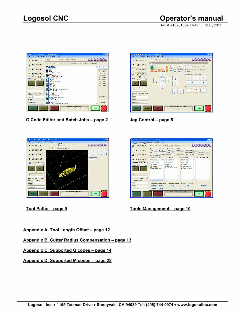
Tool Paths – page 9 Tools Management – page 10
Logosol CNC Operator’s manual Doc # 710231002 / Rev. E, 2/25/2011
Logosol, Inc. • 1155 Tasman Drive • Sunnyvale, CA 94089 Tel: (408) 744-0974 • www.logosolinc.com 2
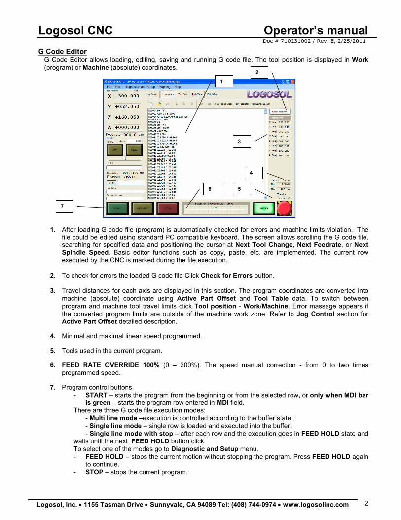
G Code Editor G Code Editor allows loading, editing, saving and running G code file. The tool position is displayed in Work (program) or Machine (absolute) coordinates.
1. After loading G code file (program) is automatically checked for errors and machine limits violation. The file could be edited using standard PC compatible keyboard. The screen allows scrolling the G code file, searching for specified data and positioning the cursor at Next Tool Change, Next Feedrate, or Next Spindle Speed. Basic editor functions such as copy, paste, etc. are implemented. The current row executed by the CNC is marked during the file execution.
2. To check for errors the loaded G code file Click Check for Errors button.
3. Travel distances for each axis are displayed in this section. The program coordinates are converted into
machine (absolute) coordinate using Active Part Offset and Tool Table data. To switch between program and machine tool travel limits click Tool position - Work/Machine. Error massage appears if the converted program limits are outside of the machine work zone. Refer to Jog Control section for Active Part Offset detailed description.
4. Minimal and maximal linear speed programmed.
5. Tools used in the current program.
6. FEED RATE OVERRIDE 100% (0 – 200%). The speed manual correction - from 0 to two times
programmed speed. 7. Program control buttons.
- START – starts the program from the beginning or from the selected row, or only when MDI bar is green – starts the program row entered in MDI field.
There are three G code file execution modes: - Multi line mode –execution is controlled according to the buffer state; - Single line mode – single row is loaded and executed into the buffer; - Single line mode with stop – after each row and the execution goes in FEED HOLD state and
waits until the next FEED HOLD button click. To select one of the modes go to Diagnostic and Setup menu. - FEED HOLD – stops the current motion without stopping the program. Press FEED HOLD again
to continue. - STOP – stops the current program.
1
3
4
5
2
7
6
Logosol CNC Operator’s manual Doc # 710231002 / Rev. E, 2/25/2011
Logosol, Inc. • 1155 Tasman Drive • Sunnyvale, CA 94089 Tel: (408) 744-0974 • www.logosolinc.com 3
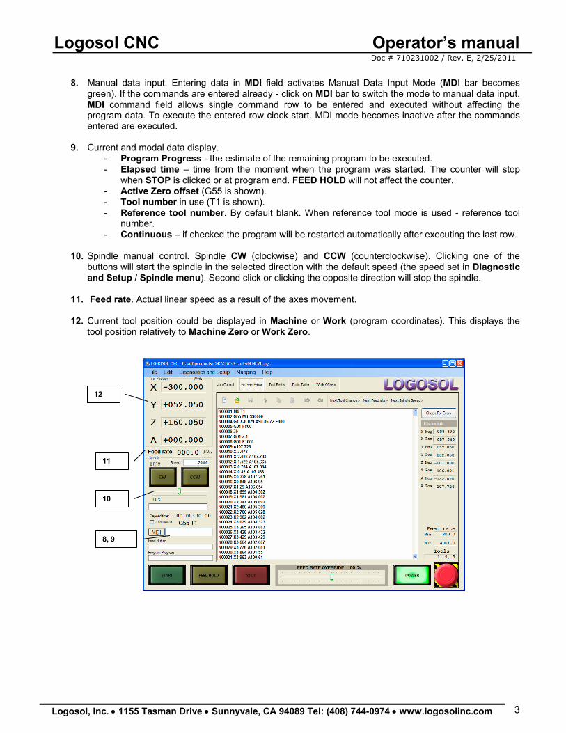
8. Manual data input. Entering data in MDI field activates Manual Data Input Mode (MDI bar becomes
green). If the commands are entered already - click on MDI bar to switch the mode to manual data input. MDI command field allows single command row to be entered and executed without affecting the program data. To execute the entered row clock start. MDI mode becomes inactive after the commands entered are executed.
9. Current and modal data display.
- Program Progress - the estimate of the remaining program to be executed. - Elapsed time – time from the moment when the program was started. The counter will stop
when STOP is clicked or at program end. FEED HOLD will not affect the counter. - Active Zero offset (G55 is shown). - Tool number in use (T1 is shown). - Reference tool number. By default blank. When reference tool mode is used - reference tool
number. - Continuous – if checked the program will be restarted automatically after executing the last row.
10. Spindle manual control. Spindle CW (clockwise) and CCW (counterclockwise). Clicking one of the buttons will start the spindle in the selected direction with the default speed (the speed set in Diagnostic and Setup / Spindle menu). Second click or clicking the opposite direction will stop the spindle.
11. Feed rate. Actual linear speed as a result of the axes movement.
12. Current tool position could be displayed in Machine or Work (program coordinates). This displays the
tool position relatively to Machine Zero or Work Zero.
10
11
12
8, 9
Logosol CNC Operator’s manual Doc # 710231002 / Rev. E, 2/25/2011
Logosol, Inc. • 1155 Tasman Drive • Sunnyvale, CA 94089 Tel: (408) 744-0974 • www.logosolinc.com 4
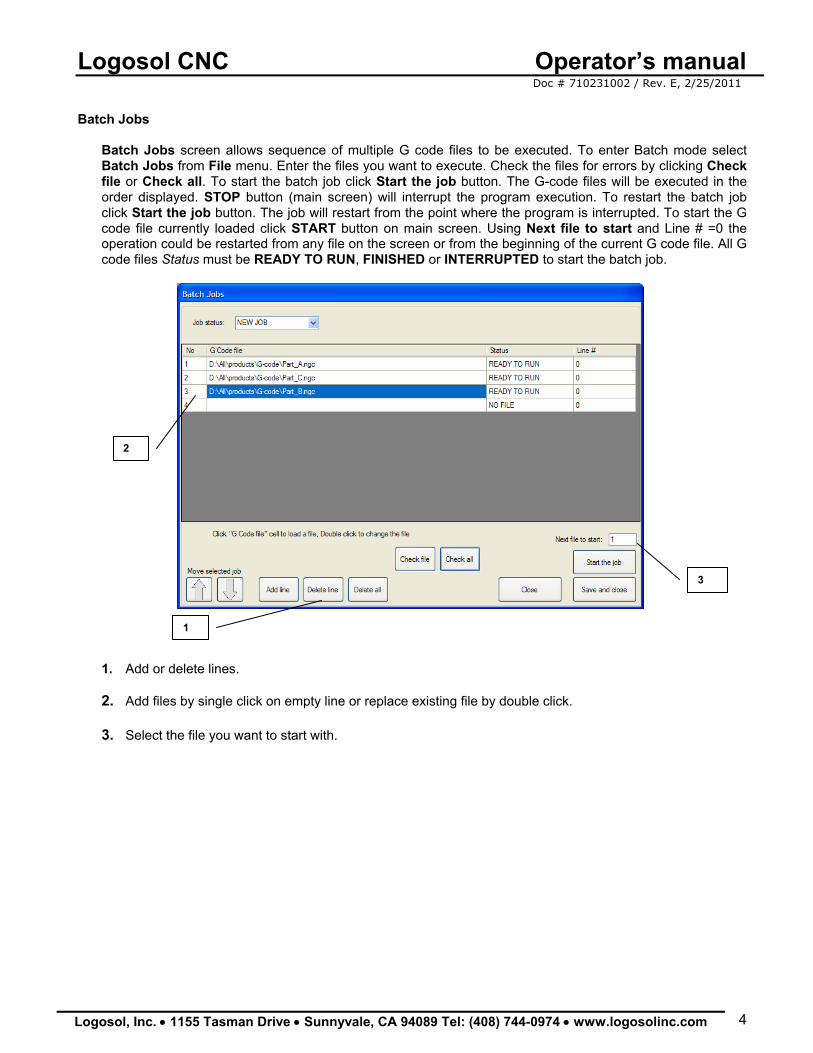
Batch Jobs
Batch Jobs screen allows sequence of multiple G code files to be executed. To enter Batch mode select Batch Jobs from File menu. Enter the files you want to execute. Check the files for errors by clicking Check file or Check all. To start the batch job click Start the job button. The G-code files will be executed in the order displayed. STOP button (main screen) will interrupt the program execution. To restart the batch job click Start the job button. The job will restart from the point where the program is interrupted. To start the G code file currently loaded click START button on main screen. Using Next file to start and Line # =0 the operation could be restarted from any file on the screen or from the beginning of the current G code file. All G code files Status must be READY TO RUN, FINISHED or INTERRUPTED to start the batch job.
1. Add or delete lines. 2. Add files by single click on empty line or replace existing file by double click.
3. Select the file you want to start with.
2
1
3
Logosol CNC Operator’s manual Doc # 710231002 / Rev. E, 2/25/2011
Logosol, Inc. • 1155 Tasman Drive • Sunnyvale, CA 94089 Tel: (408) 744-0974 • www.logosolinc.com 5
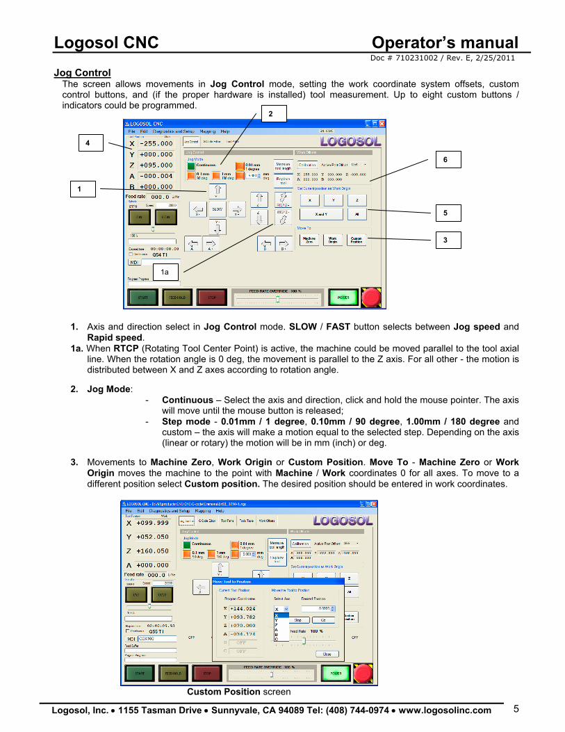
Jog Control The screen allows movements in Jog Control mode, setting the work coordinate system offsets, custom control buttons, and (if the proper hardware is installed) tool measurement. Up to eight custom buttons / indicators could be programmed.
1. Axis and direction select in Jog Control mode. SLOW / FAST button selects between Jog speed and Rapid speed.
1a. When RTCP (Rotating Tool Center Point) is active, the machine could be moved parallel to the tool axial line. When the rotation angle is 0 deg, the movement is parallel to the Z axis. For all other - the motion is distributed between X and Z axes according to rotation angle.
2. Jog Mode:
- Continuous – Select the axis and direction, click and hold the mouse pointer. The axis will move until the mouse button is released;
- Step mode - 0.01mm / 1 degree, 0.10mm / 90 degree, 1.00mm / 180 degree and custom – the axis will make a motion equal to the selected step. Depending on the axis (linear or rotary) the motion will be in mm (inch) or deg.
3. Movements to Machine Zero, Work Origin or Custom Position. Move To - Machine Zero or Work
Origin moves the machine to the point with Machine / Work coordinates 0 for all axes. To move to a different position select Custom position. The desired position should be entered in work coordinates.
Custom Position screen
1
2
3
5
4
6
1a
Logosol CNC Operator’s manual Doc # 710231002 / Rev. E, 2/25/2011
Logosol, Inc. • 1155 Tasman Drive • Sunnyvale, CA 94089 Tel: (408) 744-0974 • www.logosolinc.com 6
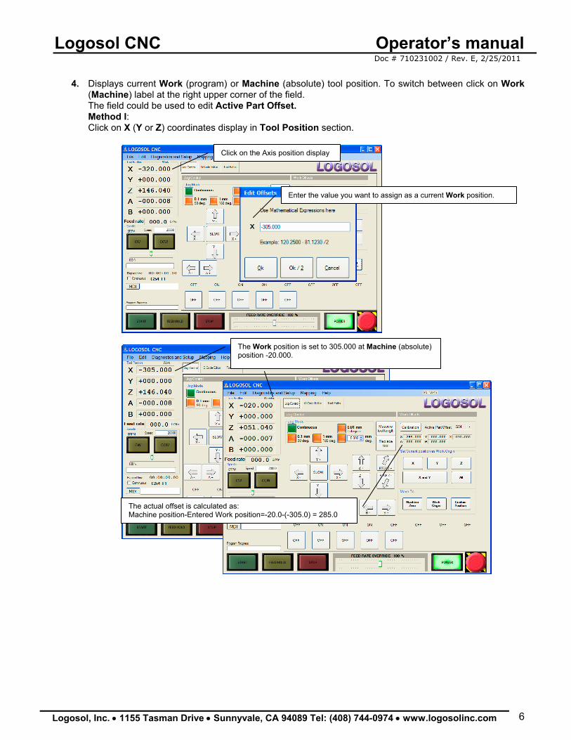
4. Displays current Work (program) or Machine (absolute) tool position. To switch between click on Work
(Machine) label at the right upper corner of the field. The field could be used to edit Active Part Offset. Method I: Click on X (Y or Z) coordinates display in Tool Position section.
Enter the value you want to assign as a current Work position.
Click on the Axis position display
The Work position is set to 305.000 at Machine (absolute) position -20.000.
The actual offset is calculated as: Machine position-Entered Work position=-20.0-(-305.0) = 285.0
Logosol CNC Operator’s manual Doc # 710231002 / Rev. E, 2/25/2011
Logosol, Inc. • 1155 Tasman Drive • Sunnyvale, CA 94089 Tel: (408) 744-0974 • www.logosolinc.com 7
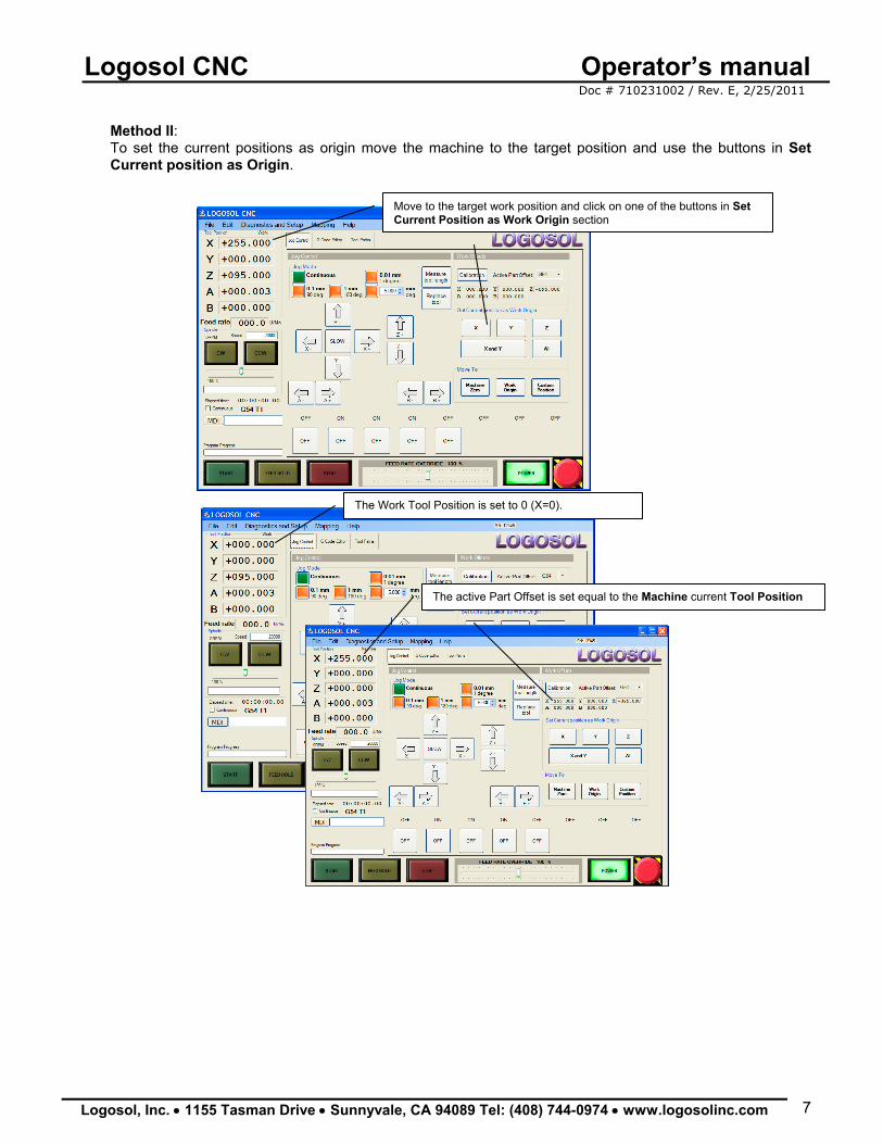
Method II: To set the current positions as origin move the machine to the target position and use the buttons in Set Current position as Origin.
Move to the target work position and click on one of the buttons in Set Current Position as Work Origin section
The Work Tool Position is set to 0 (X=0).
The active Part Offset is set equal to the Machine current Tool Position
Logosol CNC Operator’s manual Doc # 710231002 / Rev. E, 2/25/2011
Logosol, Inc. • 1155 Tasman Drive • Sunnyvale, CA 94089 Tel: (408) 744-0974 • www.logosolinc.com 8
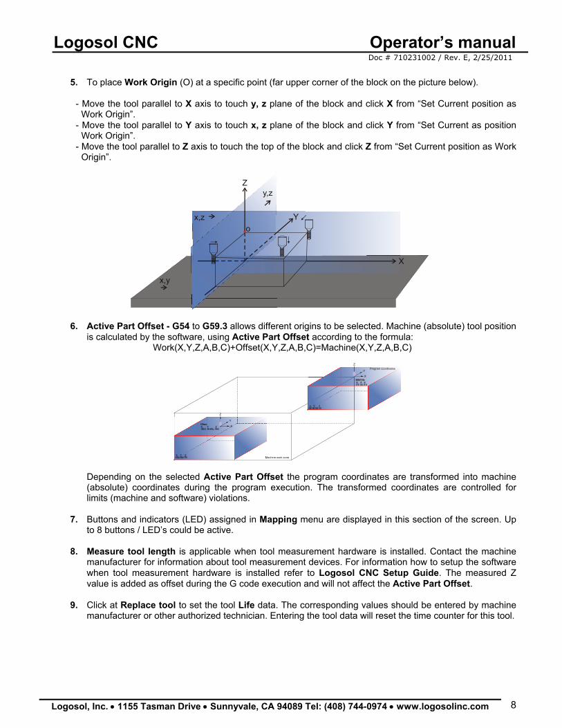
5. To place Work Origin (O) at a specific point (far upper corner of the block on the picture below).
- Move the tool parallel to X axis to touch y, z plane of the block and click X from “Set Current position as Work Origin”.
- Move the tool parallel to Y axis to touch x, z plane of the block and click Y from “Set Current as position Work Origin”.
- Move the tool parallel to Z axis to touch the top of the block and click Z from “Set Current position as Work Origin”.
x,z
x,y
y,zZ
Y
X
o
6. Active Part Offset - G54 to G59.3 allows different origins to be selected. Machine (absolute) tool position
is calculated by the software, using Active Part Offset according to the formula: Work(X,Y,Z,A,B,C)+Offset(X,Y,Z,A,B,C)=Machine(X,Y,Z,A,B,C)
X
Y
Z
Machine work zone
X
Y
ZProgram coordinates
Depending on the selected Active Part Offset the program coordinates are transformed into machine (absolute) coordinates during the program execution. The transformed coordinates are controlled for limits (machine and software) violations.
7. Buttons and indicators (LED) assigned in Mapping menu are displayed in this section of the screen. Up to 8 buttons / LED’s could be active.
8. Measure tool length is applicable when tool measurement hardware is installed. Contact the machine
manufacturer for information about tool measurement devices. For information how to setup the software when tool measurement hardware is installed refer to Logosol CNC Setup Guide. The measured Z value is added as offset during the G code execution and will not affect the Active Part Offset.
9. Click at Replace tool to set the tool Life data. The corresponding values should be entered by machine
manufacturer or other authorized technician. Entering the tool data will reset the time counter for this tool.
Logosol CNC Operator’s manual Doc # 710231002 / Rev. E, 2/25/2011
Logosol, Inc. • 1155 Tasman Drive • Sunnyvale, CA 94089 Tel: (408) 744-0974 • www.logosolinc.com 9
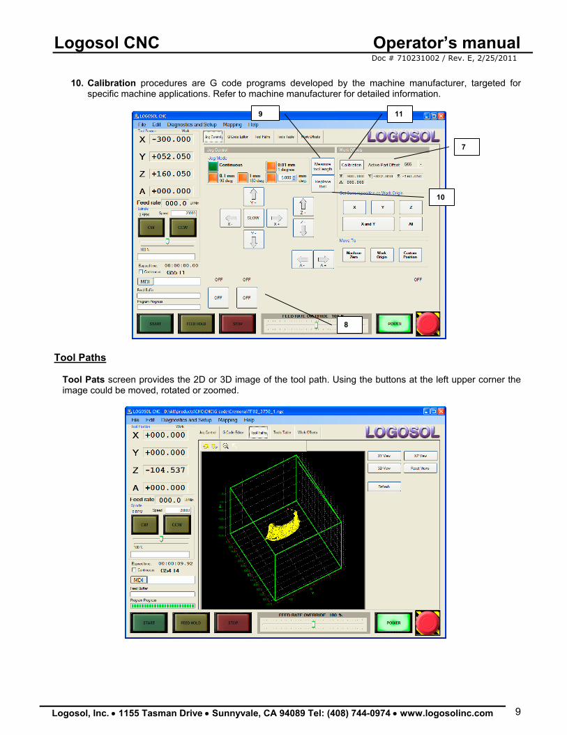
10. Calibration procedures are G code programs developed by the machine manufacturer, targeted for
specific machine applications. Refer to machine manufacturer for detailed information.
Tool Paths
Tool Pats screen provides the 2D or 3D image of the tool path. Using the buttons at the left upper corner the image could be moved, rotated or zoomed.
7
8
9
10
11
Logosol CNC Operator’s manual Doc # 710231002 / Rev. E, 2/25/2011
Logosol, Inc. • 1155 Tasman Drive • Sunnyvale, CA 94089 Tel: (408) 744-0974 • www.logosolinc.com 10
Tools management
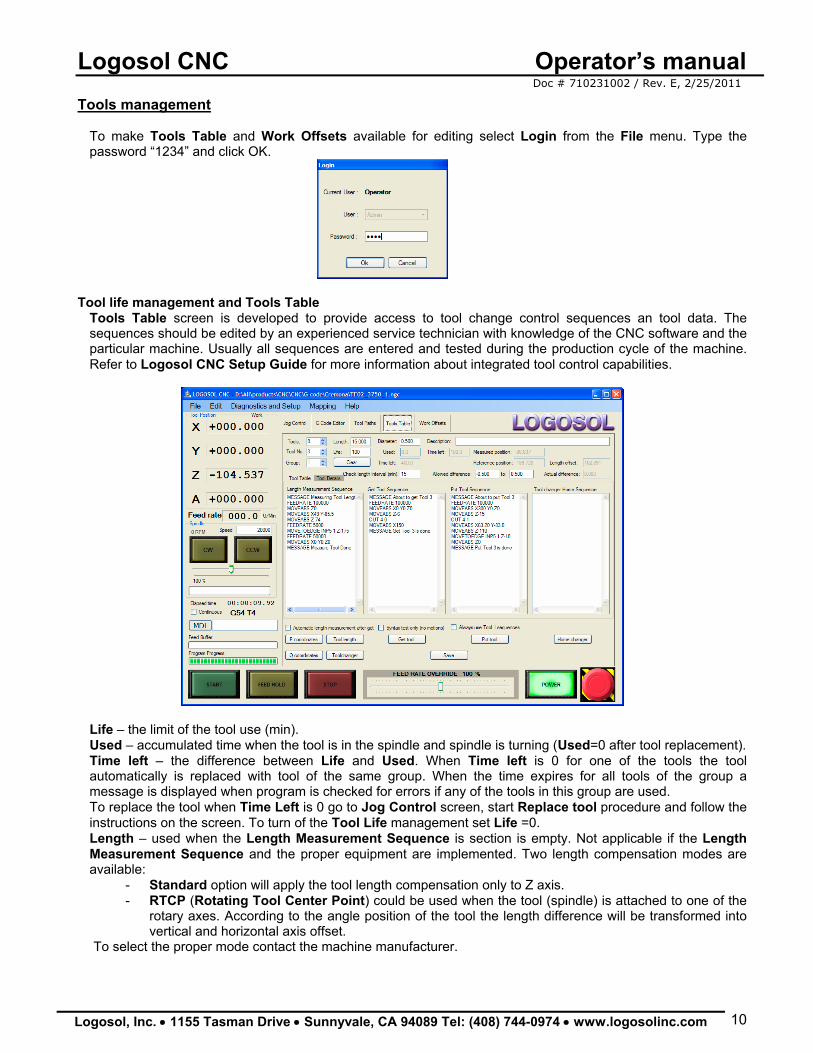
To make Tools Table and Work Offsets available for editing select Login from the File menu. Type the password “1234” and click OK.
Tool life management and Tools Table
Tools Table screen is developed to provide access to tool change control sequences an tool data. The sequences should be edited by an experienced service technician with knowledge of the CNC software and the particular machine. Usually all sequences are entered and tested during the production cycle of the machine. Refer to Logosol CNC Setup Guide for more information about integrated tool control capabilities.
Life – the limit of the tool use (min). Used – accumulated time when the tool is in the spindle and spindle is turning (Used=0 after tool replacement). Time left – the difference between Life and Used. When Time left is 0 for one of the tools the tool automatically is replaced with tool of the same group. When the time expires for all tools of the group a message is displayed when program is checked for errors if any of the tools in this group are used. To replace the tool when Time Left is 0 go to Jog Control screen, start Replace tool procedure and follow the instructions on the screen. To turn of the Tool Life management set Life =0. Length – used when the Length Measurement Sequence is section is empty. Not applicable if the Length Measurement Sequence and the proper equipment are implemented. Two length compensation modes are available:
- Standard option will apply the tool length compensation only to Z axis. - RTCP (Rotating Tool Center Point) could be used when the tool (spindle) is attached to one of the
rotary axes. According to the angle position of the tool the length difference will be transformed into vertical and horizontal axis offset.
To select the proper mode contact the machine manufacturer.
Logosol CNC Operator’s manual Doc # 710231002 / Rev. E, 2/25/2011
Logosol, Inc. • 1155 Tasman Drive • Sunnyvale, CA 94089 Tel: (408) 744-0974 • www.logosolinc.com 11
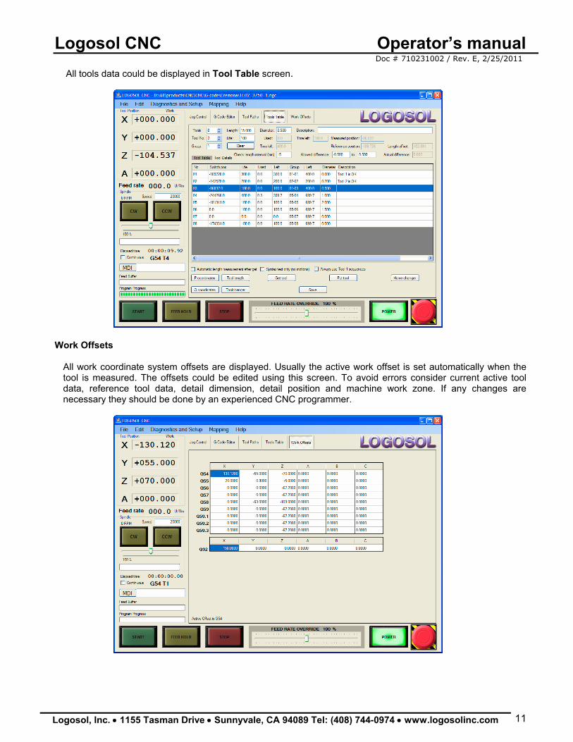
All tools data could be displayed in Tool Table screen.
Work Offsets
All work coordinate system offsets are displayed. Usually the active work offset is set automatically when the tool is measured. The offsets could be edited using this screen. To avoid errors consider current active tool data, reference tool data, detail dimension, detail position and machine work zone. If any changes are necessary they should be done by an experienced CNC programmer.
Logosol CNC Operator’s manual Doc # 710231002 / Rev. E, 2/25/2011
Logosol, Inc. • 1155 Tasman Drive • Sunnyvale, CA 94089 Tel: (408) 744-0974 • www.logosolinc.com 12
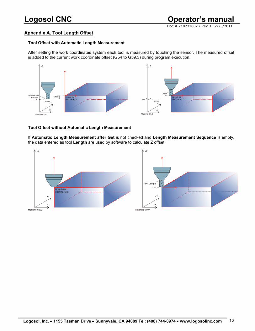
Appendix A. Tool Length Offset
Tool Offset with Automatic Length Measurement After setting the work coordinates system each tool is measured by touching the sensor. The measured offset is added to the current work coordinate offset (G54 to G59.3) during program execution.
+Z
+Y
+X
+Z
+Y
+X
Machine 0,0,0 Machine 0,0,0
Work 0,0,0Machine x,y,z
Work 0,0,0Machine x,y,z
Offset
sensor sensor
Tx Measured Position
Offset
Tool Offset without Automatic Length Measurement If Automatic Length Measurement after Get is not checked and Length Measurement Sequence is empty, the data entered as tool Length are used by software to calculate Z offset.
Tool Lenght
+Z
+Y
+X
+Z
+Y
+X
Machine 0,0,0 Machine 0,0,0
Work 0,0,0Machine x,y,z
Logosol CNC Operator’s manual Doc # 710231002 / Rev. E, 2/25/2011
Logosol, Inc. • 1155 Tasman Drive • Sunnyvale, CA 94089 Tel: (408) 744-0974 • www.logosolinc.com 13
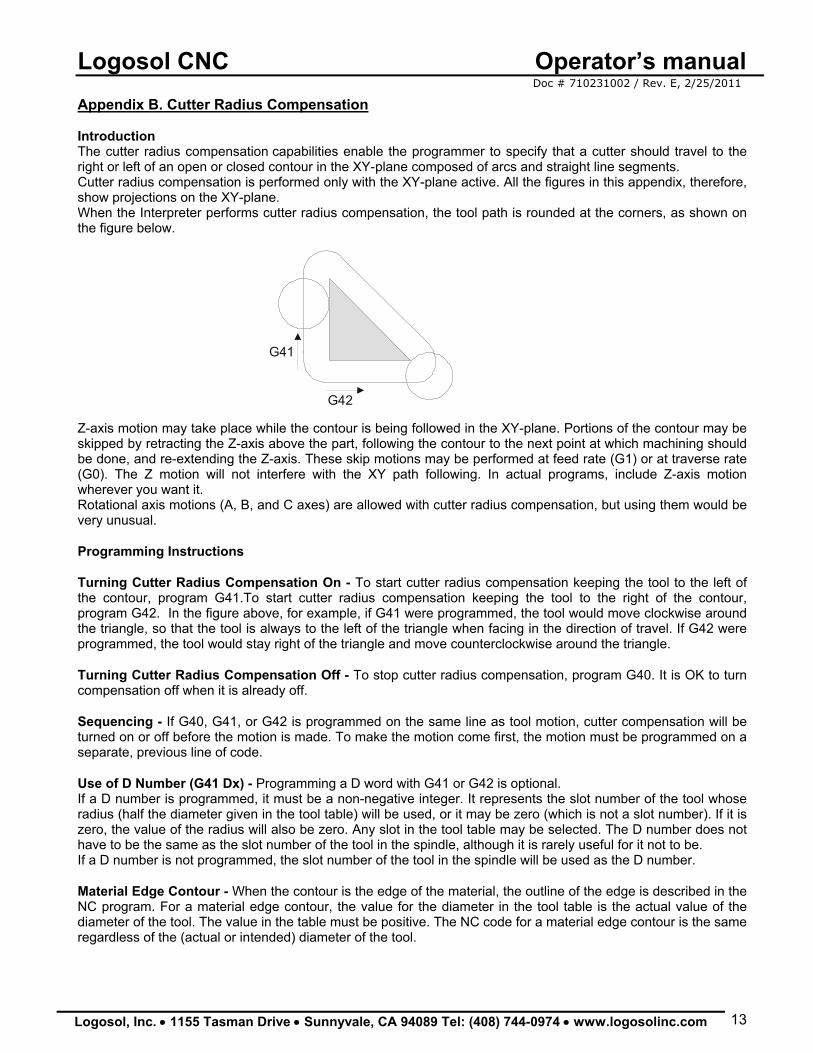
Appendix B. Cutter Radius Compensation Introduction The cutter radius compensation capabilities enable the programmer to specify that a cutter should travel to the right or left of an open or closed contour in the XY-plane composed of arcs and straight line segments. Cutter radius compensation is performed only with the XY-plane active. All the figures in this appendix, therefore, show projections on the XY-plane. When the Interpreter performs cutter radius compensation, the tool path is rounded at the corners, as shown on the figure below.
G41
G42 Z-axis motion may take place while the contour is being followed in the XY-plane. Portions of the contour may be skipped by retracting the Z-axis above the part, following the contour to the next point at which machining should be done, and re-extending the Z-axis. These skip motions may be performed at feed rate (G1) or at traverse rate (G0). The Z motion will not interfere with the XY path following. In actual programs, include Z-axis motion wherever you want it. Rotational axis motions (A, B, and C axes) are allowed with cutter radius compensation, but using them would be very unusual. Programming Instructions
Turning Cutter Radius Compensation On - To start cutter radius compensation keeping the tool to the left of the contour, program G41.To start cutter radius compensation keeping the tool to the right of the contour, program G42. In the figure above, for example, if G41 were programmed, the tool would move clockwise around the triangle, so that the tool is always to the left of the triangle when facing in the direction of travel. If G42 were programmed, the tool would stay right of the triangle and move counterclockwise around the triangle. Turning Cutter Radius Compensation Off - To stop cutter radius compensation, program G40. It is OK to turn compensation off when it is already off. Sequencing - If G40, G41, or G42 is programmed on the same line as tool motion, cutter compensation will be turned on or off before the motion is made. To make the motion come first, the motion must be programmed on a separate, previous line of code. Use of D Number (G41 Dx) - Programming a D word with G41 or G42 is optional. If a D number is programmed, it must be a non-negative integer. It represents the slot number of the tool whose radius (half the diameter given in the tool table) will be used, or it may be zero (which is not a slot number). If it is zero, the value of the radius will also be zero. Any slot in the tool table may be selected. The D number does not have to be the same as the slot number of the tool in the spindle, although it is rarely useful for it not to be. If a D number is not programmed, the slot number of the tool in the spindle will be used as the D number. Material Edge Contour - When the contour is the edge of the material, the outline of the edge is described in the NC program. For a material edge contour, the value for the diameter in the tool table is the actual value of the diameter of the tool. The value in the table must be positive. The NC code for a material edge contour is the same regardless of the (actual or intended) diameter of the tool.
Logosol CNC Operator’s manual Doc # 710231002 / Rev. E, 2/25/2011
Logosol, Inc. • 1155 Tasman Drive • Sunnyvale, CA 94089 Tel: (408) 744-0974 • www.logosolinc.com 14
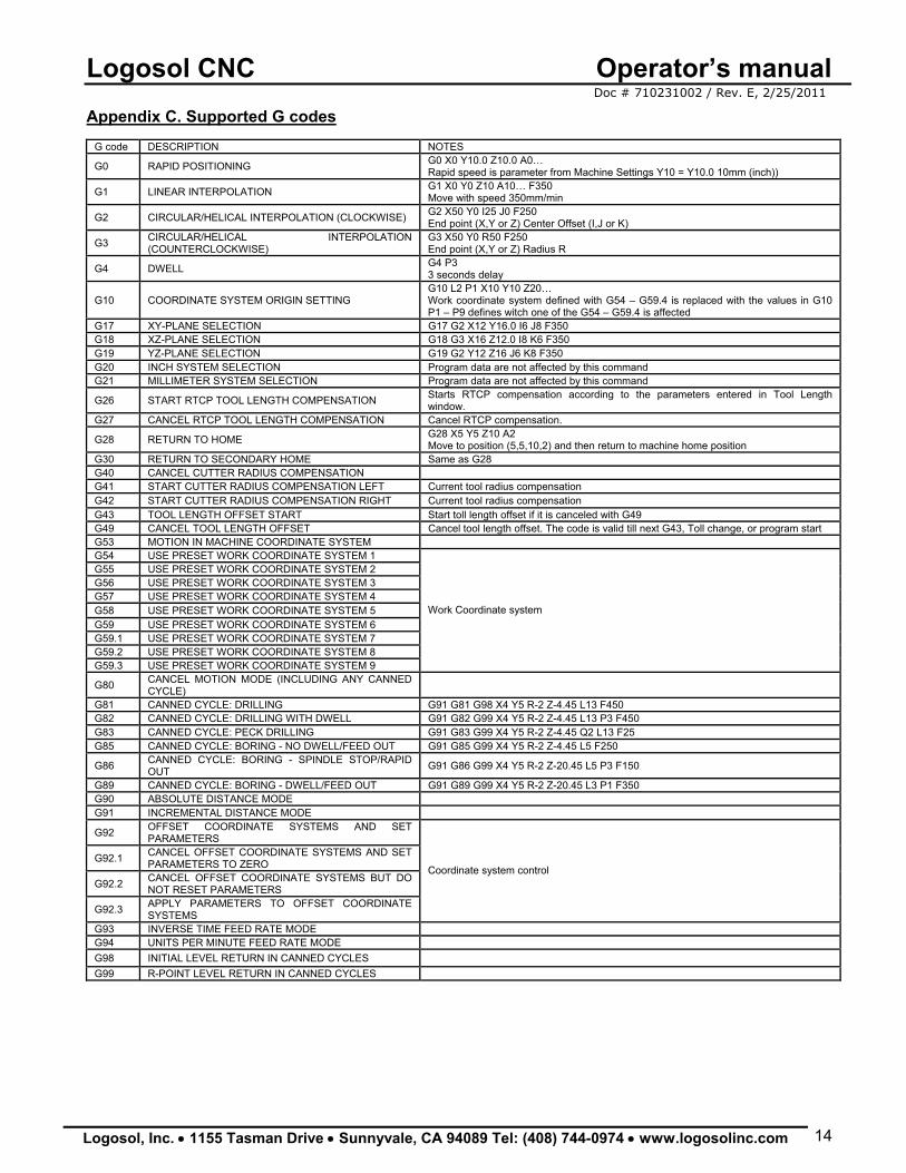
Appendix C. Supported G codes CMD
G code DESCRIPTION NOTES
G0 RAPID POSITIONING G0 X0 Y10.0 Z10.0 A0… Rapid speed is parameter from Machine Settings Y10 = Y10.0 10mm (inch))
G1 LINEAR INTERPOLATION G1 X0 Y0 Z10 A10… F350 Move with speed 350mm/min
G2 CIRCULAR/HELICAL INTERPOLATION (CLOCKWISE) G2 X50 Y0 I25 J0 F250 End point (X,Y or Z) Center Offset (I,J or K)
G3 CIRCULAR/HELICAL INTERPOLATION (COUNTERCLOCKWISE)
G3 X50 Y0 R50 F250 End point (X,Y or Z) Radius R
G4 DWELL G4 P3 3 seconds delay
G10 COORDINATE SYSTEM ORIGIN SETTING G10 L2 P1 X10 Y10 Z20… Work coordinate system defined with G54 – G59.4 is replaced with the values in G10 P1 – P9 defines witch one of the G54 – G59.4 is affected
G17 XY-PLANE SELECTION G17 G2 X12 Y16.0 I6 J8 F350 G18 XZ-PLANE SELECTION G18 G3 X16 Z12.0 I8 K6 F350 G19 YZ-PLANE SELECTION G19 G2 Y12 Z16 J6 K8 F350 G20 INCH SYSTEM SELECTION Program data are not affected by this command G21 MILLIMETER SYSTEM SELECTION Program data are not affected by this command
G26 START RTCP TOOL LENGTH COMPENSATION Starts RTCP compensation according to the parameters entered in Tool Length window.
G27 CANCEL RTCP TOOL LENGTH COMPENSATION Cancel RTCP compensation.
G28 RETURN TO HOME G28 X5 Y5 Z10 A2 Move to position (5,5,10,2) and then return to machine home position
G30 RETURN TO SECONDARY HOME Same as G28 G40 CANCEL CUTTER RADIUS COMPENSATION G41 START CUTTER RADIUS COMPENSATION LEFT Current tool radius compensation G42 START CUTTER RADIUS COMPENSATION RIGHT Current tool radius compensation G43 TOOL LENGTH OFFSET START Start toll length offset if it is canceled with G49 G49 CANCEL TOOL LENGTH OFFSET Cancel tool length offset. The code is valid till next G43, Toll change, or program start G53 MOTION IN MACHINE COORDINATE SYSTEM G54 USE PRESET WORK COORDINATE SYSTEM 1 G55 USE PRESET WORK COORDINATE SYSTEM 2 G56 USE PRESET WORK COORDINATE SYSTEM 3 G57 USE PRESET WORK COORDINATE SYSTEM 4 G58 USE PRESET WORK COORDINATE SYSTEM 5 G59 USE PRESET WORK COORDINATE SYSTEM 6 G59.1 USE PRESET WORK COORDINATE SYSTEM 7 G59.2 USE PRESET WORK COORDINATE SYSTEM 8 G59.3 USE PRESET WORK COORDINATE SYSTEM 9
Work Coordinate system
G80 CANCEL MOTION MODE (INCLUDING ANY CANNED CYCLE)
G81 CANNED CYCLE: DRILLING G91 G81 G98 X4 Y5 R-2 Z-4.45 L13 F450 G82 CANNED CYCLE: DRILLING WITH DWELL G91 G82 G99 X4 Y5 R-2 Z-4.45 L13 P3 F450 G83 CANNED CYCLE: PECK DRILLING G91 G83 G99 X4 Y5 R-2 Z-4.45 Q2 L13 F25 G85 CANNED CYCLE: BORING - NO DWELL/FEED OUT G91 G85 G99 X4 Y5 R-2 Z-4.45 L5 F250
G86 CANNED CYCLE: BORING - SPINDLE STOP/RAPID OUT G91 G86 G99 X4 Y5 R-2 Z-20.45 L5 P3 F150
G89 CANNED CYCLE: BORING - DWELL/FEED OUT G91 G89 G99 X4 Y5 R-2 Z-20.45 L3 P1 F350 G90 ABSOLUTE DISTANCE MODE G91 INCREMENTAL DISTANCE MODE
G92 OFFSET COORDINATE SYSTEMS AND SET PARAMETERS
G92.1 CANCEL OFFSET COORDINATE SYSTEMS AND SET PARAMETERS TO ZERO
G92.2 CANCEL OFFSET COORDINATE SYSTEMS BUT DO NOT RESET PARAMETERS
G92.3 APPLY PARAMETERS TO OFFSET COORDINATE SYSTEMS
Coordinate system control
G93 INVERSE TIME FEED RATE MODE G94 UNITS PER MINUTE FEED RATE MODE G98 INITIAL LEVEL RETURN IN CANNED CYCLES G99 R-POINT LEVEL RETURN IN CANNED CYCLES
Logosol CNC Operator’s manual Doc # 710231002 / Rev. E, 2/25/2011
Logosol, Inc. • 1155 Tasman Drive • Sunnyvale, CA 94089 Tel: (408) 744-0974 • www.logosolinc.com 15
The basic G code format used is: GXX X.. Y.. Z.. I.. J.. K.. P.. Data format: Metric data format is 123.456 mm. Inch data format is 12.3456 inch. Delay format 123.456 sec. Note: Once, set the metric or inch input data format should not be changed during the machine operation. Any changes may affect the machine accuracy and safety. Consult machine manufacturer prior.
Examples: G0 X10 Y-10.0 Z0.33 (moves the tool at work position X=10 Y=-10 and Z=0.33) Z.75 (moves the tool at work position Z=0.75). G4 P4 (4 sec delay). G4 P0.4 (0.4 sec delay).
G0 Rapid Travel G0 moves the machine from one point to another point at the Rapid speed of the machine. G0 is generally used when cutting will not take place when moving from one location to another. G0 is modal and will remain in effect until it is canceled by the G1, G2 or G3 codes. G0 will not cancel any feed rates used by the interpolation modes. An F word can appear on the same line with a G0 code, however, the F word will only be used when an interpolation code is used. G1 Linear Interpolation This code is used for linear interpolation. Linear moves can be made by one, or any combination of, all the active axes.
Eexample G0 and G1 : F30. (This F word is modal). G0 Z.1 (This line will be in rapid travel). X1.3 Y2.7 (This line will be in rapid travel). G1 Z-10.245 (The G1 will cancel the G0 and use the F30. from above). X.5 (This will be at F30.0). Z.1 G0 (This line will be in rapid travel).
G2 Circular Interpolation Arc Clockwise G2 is used for CW circular interpolation.
Example center offset: G2 X50 Y0 I25 J0 F250 (X and Y – end point, I and J – center offset) Example radius: G2 X50 Y0 R50 F250 (X and Y – end point, R – radius)
G3 Circular Interpolation Arc Counterclockwise G3 is used for CCW circular interpolation.
Example center offset: G3 X50 Z0 I25 J0 F250 (X and Z – end point, I and J – center offset) Example radius: G3 X50 YZ0 R50 F250 (X and Z – end point, R – radius)
Logosol CNC Operator’s manual Doc # 710231002 / Rev. E, 2/25/2011
Logosol, Inc. • 1155 Tasman Drive • Sunnyvale, CA 94089 Tel: (408) 744-0974 • www.logosolinc.com 16
G4 Dwell Whenever a pause in the program is required, use the G4 code. A pause may be used to allow coolant to fully turn on after using the M7 or M8 codes.
Example: G0 X10 EXAMPLE: G90 G0 S10000 M3 X-.45 Y-.2 Z-.3 M8 G4 P1 (This one second dwell allows the coolant to turn on completely). X3. G1 F80. - A P word represents time. The time is given in seconds - P1 = 1 second - P0.5 = 1/2 second - P60 = 1 minute
G10 Coordinate system origin setting To set the coordinate values for the origin of a coordinate system, program G10 L2 P … X… Y… Z… A… B… C…, where the P number must evaluate to an integer in the range 1 to 9 (corresponding to G54 to G59.3) and all axis words are optional. The coordinates of the origin of the coordinate system specified by the P number are reset to the coordinate values given (in terms of the absolute coordinate system). Only those coordinates for which an axis word is included on the line will be reset. If origin offsets (made by G92 or G92.3) were in effect before G10 is used, they will continue to be in effect afterwards. The coordinate system whose origin is set by a G10 command may be active or inactive at the time the G10 is executed.
Example: G10 L2 P1 X3.5 Y17.2
The line above sets the origin of the first coordinate system (the one selected by G54) to a point where X is 3.5 and Y is 17.2 (in absolute coordinates). The Z coordinate of the origin (and the coordinates for any rotational axes) are whatever those coordinates of the origin were before the line was executed. G17, G18, and G19 Plane selection Circular (G2 and G3) interpolation plane selection. Program G17 to select the XY-plane, G18 to select the XZ-plane, or G19 to select the YZ-plane. G20 and G21 - Length Units Program G20 to use inches for length units. Program G21 to use millimeters. It is usually a good idea to program either G20 or G21 near the beginning of a program before any motion occurs, and not to use either one anywhere else in the program. It is the responsibility of the user to be sure all numbers are appropriate for use with the current length units.
Logosol CNC Operator’s manual Doc # 710231002 / Rev. E, 2/25/2011
Logosol, Inc. • 1155 Tasman Drive • Sunnyvale, CA 94089 Tel: (408) 744-0974 • www.logosolinc.com 17
G26 and G27 RTCP tool length compensation mode G26 activates RTCP (Rotating Tool Center Point) compensation if mode is enabled in Tool Length compensation setup screen. G27 switches to standard (Z axis mode only) compensation.
Example: G0 X0 Z30 (Z axis only compensation) G26 G0 A15 (RTCP is on and the compensation is applied to X and Z or Y and Z depend on Tool length compensation setup) G1 X50 Y40 F500 G0 A0 G27 G0 X15 Z25 (Z axis only compensation) G28 and G30 Return to Home position To return to home position by way of the programmed position, program G28 X… Y… Z… A…B… C… (or use G30). All axis words are optional. The path is made by a traverse move from the current position to the programmed position, followed by a traverse move to the home position. If no axis words are programmed, the intermediate point is the current point, so only one move is made. Example: G28 X10 Y.5 Z-14 (move to X=10, Y=0.5 and Z=-14 and after that to Home) G40 Cutter Compensation Cancel To stop cutter radius compensation, program G40. It is OK to turn compensation off when it is already off. This code is used to cancel cutter radius compensation. G41 and G42 Cutter Compensation The cutter radius compensation capabilities enable the programmer to specify that a cutter should travel to the right or left of an open or closed contour in the XY-plane composed of arcs and straight line segments. Cutter radius compensation is performed only with the XY-plane active. All the figures in this appendix, therefore, show projections on the XY-plane. Z-axis motion may take place while the contour is being followed in the XY-plane. Portions of the contour may be skipped by retracting the Z-axis above the part, following the contour to the next point at which machining should be done, and re-extending the Z-axis. These skip motions may be performed at feed rate (G1) or at traverse rate (G0). The Z motion will not interfere with the XY path following. In actual programs, include Z-axis motion wherever you want it. To start cutter radius compensation keeping the tool to the left of the contour, program G41.To start cutter radius compensation keeping the tool to the right of the contour, program G42. For example, if G41 were programmed, the tool would move clockwise around the triangle, so that the tool is always to the left of the triangle when facing in the direction of travel. If G42 were programmed, the tool would stay right of the triangle and move counterclockwise around the triangle. If G40, G41, or G42 is programmed on the same line as tool motion, cutter compensation will be turned on or off before the motion is made. To make the motion come first, the motion must be programmed on a separate, previous line of code. G41 Dx - Programming a D word with G41 or G42 is optional. If a D number is programmed, it must be a non-negative integer. It represents the slot number of the tool whose radius (half the diameter given in the tool table) will be used, or it may be zero (which is not a slot number). If it is zero, the value of the radius will also be zero. Any slot in the tool table may be selected. The D number does not have to be the same as the slot number of the tool in the spindle, although it is rarely useful for it not to be. If a D number is not programmed, the slot number of the tool in the spindle will be used as the D number.
Logosol CNC Operator’s manual Doc # 710231002 / Rev. E, 2/25/2011
Logosol, Inc. • 1155 Tasman Drive • Sunnyvale, CA 94089 Tel: (408) 744-0974 • www.logosolinc.com 18
When the contour is the edge of the material, the outline of the edge is described in the NC program. For a material edge contour, the value for the diameter in the tool table is the actual value of the diameter of the tool. The value in the table must be positive. The NC code for a material edge contour is the same regardless of the (actual or intended) diameter of the tool.
Example (G41): G40 (Cutter Compensation is off) G0 X90 Y-10 (move to initial position) G41 G1 X100 Y-5 F500 (start the Cutter Compensation) Y10 X150 Y0 X95 G40 (Cutter Compensation is off)
Example (G42):
G40 G0 X90 Y-5 G42 G1 X95 Y0 F500 X150 X100 Y10 Y-5 G40
G43 and G49 Tool Length Compensation G43 is used to apply tool length compensation to the Z axis. By default this code is active after power up. Example: G49 G1 X100 Z20 G43 H1 G1 X25 Z20 G53 Move in Absolute Coordinates For linear motion to a point expressed in absolute coordinates, program G1 G53 X… Y… Z… A… B… C… (or use G0 instead of G1), where all the axis words are optional, except that at least one must be used. The G0 or G1 is optional if it is the current motion mode. G53 is not modal and must be programmed on each line on which it is intended to be active. This will produce coordinated linear motion to the programmed point. G53 can be used only when G0 or G1 is active. G53 can not be used while cutter radius ompensation is on (G41 or G42). Example: G53 G0 X145 Y24 (moves the tool to machine position X=145 and Y=24) G1 X12 Z10.5 (moves the to coordinates X=12 and Z=10.5 of the active work coordinate system
selected with G54 to G59.3) G54 to G59.3 Use Preset Coordinate System To select coordinate system 1, program G54, and similarly for other coordinate systems. The coordinate system can not be changed while cutter radius compensation is on (G41 or G42). G80 Cancel Modal Motion G80 will cancel any motion including any canned cycle.
Logosol CNC Operator’s manual Doc # 710231002 / Rev. E, 2/25/2011
Logosol, Inc. • 1155 Tasman Drive • Sunnyvale, CA 94089 Tel: (408) 744-0974 • www.logosolinc.com 19
Canned Cycles All canned cycles are performed with respect to the currently selected plane. Any of the three planes (XY, YZ, ZX) may be selected. Throughout this section, most of the descriptions assume the XY-plane has been selected. The behavior is always analogous if the YZ or XZ-plane is selected. Rotational axis words are allowed in canned cycles, but it is better to omit them. If rotational axis words are used, the numbers must be the same as the current position numbers so that the rotational axes do not move. In incremental distance mode: when the XY-plane is selected, X, Y, and R numbers are treated as increments to the current position and Z as an increment from the Z-axis position before the move involving Z takes place; when the YZ or XZ-plane is selected, treatment of the axis words is analogous. In absolute distance mode, the X, Y, R, and Z numbers are absolute positions in the active coordinate system. The L number is optional and represents the number of repeats. L=0 is not allowed. If the repeat feature is used, it is normally used in incremental distance mode, so that the same sequence of motions is repeated in several equally spaced places along a straight line. In absolute distance mode, L > 1 means “do the same cycle in the same place several times”. Omitting the L word is equivalent to specifying L=1. When L>1 in incremental mode with the XY-plane selected, the X and Y positions are determined by adding the given X and Y numbers either to the current X and Y positions (on the first go-around) or to the X and Y positions at the end of the previous go-around (on the repetitions). The R and Z positions do not change during the repeats. The height of the retract move at the end of each repeat (called “clear Z” in the descriptions below) is determined by the setting of the retract mode: either to the original Z position (if that is above the R position and in G98 mode), or otherwise to the R position. Preliminary and In-Between Motion At the very beginning of the execution of any of the canned cycles, with the XY-plane selected, if the current Z position is below the R position, the Z-axis is traversed to the R position. This happens only once, regardless of the value of L. In addition, at the beginning of the first cycle and each repeat, the following one or two moves are made:
- A straight rapid travel parallel to the XY-plane to the given XY-position; - A straight traverse of the Z-axis only to the R position, if it is not already at the R position.
If the XZ or YZ plane is active, the preliminary and in-between motions are analogous. G81 Cycle The G81 cycle is intended for drilling. Program G81 X… Y… Z… A… B… C… R… L.
Example 1: Initial position X=1, Y=2 and Z=3 G90 G81 G98 X4 Y5 Z1.5 R2.8
The cycle is G81 (drilling) and will be performed once. The distance mode is absolute (G90) and initial level return (G98) is selected. The following moves take place:
- A rapid motion parallel to the XY-plane to position X=4 and Y=5; - A rapid motion of the Z-axis to Z=2.8; - A feed motion of the Z-axis to Z=1.5 (drilling); - A rapid motion of the Z-axis to Z=3.
Logosol CNC Operator’s manual Doc # 710231002 / Rev. E, 2/25/2011
Logosol, Inc. • 1155 Tasman Drive • Sunnyvale, CA 94089 Tel: (408) 744-0974 • www.logosolinc.com 20
Example 2: Initial position X=1, Y=2 and Z=3
G91 G81 G98 X4 Y5 Z-0.6 R1.8 L3
The cycle is G81 (drilling) and will be performed three times. The distance mode is relative (G91) and initial level return (G98) is selected. The cycle initial positions are X=5 (=1+4), Y=7 (=2+5), and Z=4.8 (=1.8+3). The Z position is 4.2 (=4.8-0.6). The preliminary motion is a rapid travel along the Z-axis to Z=4.8. The first repeat consists of 3 moves:
- A rapid motion parallel to the XY-plane to X=5 and Y=7; - A feed motion of the Z-axis to Z=4.2 (drilling); - A rapid motion to the Z-axis to Z=4.8.
The second repeat initial position are: X=9 (=5+4) and Y=12 (=7+5). The second repeat consists of 3 moves:
- A rapid motion parallel to the XY-plane to X=9 and Y=12; - A feed motion of the Z-axis to Z=4.2 (drilling); - A rapid motion to the Z-axis to Z=4.8.
The third repeat initial positions are: X=13 (=9+4) and Y=17 (=12+5). The third repeat consists of 3 moves:
- A rapid motion parallel to the XY-plane to X=13 and Z=17 - A feed motion of the Z-axis to Z=4.2 (drilling); - A rapid motion to the Z-axis to Z=4.8.
G82 Cycle The G82 cycle is intended for drilling. Program G82 X… Y… Z… A… B… C… R… L… P… G82 is similar to G81 and has the same motions sequences. The difference is the delay P seconds after feed motion of Z-axis (drilling) Example:
G90 G82 G98 X4 Y5 Z1.5 R2.8 P0.5 (0.5sec delay at Z=1.5) G83 Cycle The G83 cycle (often called peck drilling) is intended for deep drilling or milling with chip breaking. The retracts in this cycle clear the hole of chips and cut off any long stringers (which are common when drilling in aluminum). This cycle takes a Q number which represents a “delta” increment along the Z-axis. Program G83 X… Y… Z… A… B… C… R… L… Q… The X and Y-axes behavior is the same as in G81. The Z-axis motion is divided on Q steps. After each step Z-axis moves to its initial position with rapid travel.
Example: G91 G83 G98 X4 Y1 R-2 Z-40 Q5
In the example above the drilling distance is divided into 5 steps until the final Z-axis position is reached. After each step Z-axis returns to its initial position with rapid speed and then moves to the end Z-axis position of the previous step. G85 Cycle The G85 cycle is intended for boring or reaming, but could be used for drilling or milling. Program G85 X… Y… Z… A… B… C… R… L… Preliminary motion is same as described in G81. All other Z-axis motions are at feed rate speed.
Logosol CNC Operator’s manual Doc # 710231002 / Rev. E, 2/25/2011
Logosol, Inc. • 1155 Tasman Drive • Sunnyvale, CA 94089 Tel: (408) 744-0974 • www.logosolinc.com 21
G86 Cycle The G86 cycle is intended for boring. This cycle uses a P number for the number of seconds to dwell. Program G86 X… Y… Z… A… B… C… R… L… P… Preliminary motion is same as described in G81. The Z-axis motions in this cycle are:
- Move the Z-axis only at the current feed rate to the Z position; - Dwell for the P number of seconds; - Stop the spindle turning; - Retract the Z-axis at traverse rate to initial Z; - Restart the spindle in the direction it was going;
The spindle must be turning before this cycle is used. G89 Cycle The G89 cycle is intended for boring. This cycle uses a P number, where P specifies the number of seconds to dwell. Program G89 X… Y… Z… A… B… C… R… L… P… Preliminary motion is same as described in G81. The Z-axis motions in this cycle are
- Move the Z-axis only at the current feed rate to the Z position. - Dwell for the P number of seconds. - Retract the Z-axis at the current feed rate to inital Z.
G90 and G91 Absolute and incremental distance mode To go into absolute distance mode, program G90. In absolute distance mode, axis numbers (X, Y, Z, A, B, C) usually represent positions in terms of the currently active coordinate system. To go into incremental distance mode, program G91. In incremental distance mode, axis numbers (X, Y, Z, A, B, C) usually represent increments from the current values of the numbers. I, J and K numbers always represent increments, regardless of the distance mode setting. G92, G92.1, G92.2, G92.3 - Coordinate System Offsets G92 will make the current point have the coordinates you want (without motion), program G92 X… Y… Z… A… B… C…, where the axis words contain the axis numbers you want. All axis words are optional, except that at least one must be used. If an axis word is not used for a given axis, the coordinate on that axis of the current point is not changed. When G92 is executed, the origin of the currently active coordinate system moves. The offset programmed with G92 is stored in Work Offsets table. G92.1 cancels the offset and clears the G92 offset data in Work Offsets table. G92.2 cancels the offset but will keep the data in Work Offsets table. G92.3 activates the offset and applies the offset data stored in Work Offsets table. Example: Suppose the current point is at X=4 in the currently specified coordinate system and the current X-axis offset is zero, then G92 X7 sets the X-axis offset to -3. The axis offsets are always used when motion is specified in absolute distance mode using any of the nine coordinate systems (those designated by G54 - G59.3). Thus all nine coordinate systems are affected by G92. Being in incremental distance mode has no effect on the action of G92. Non-zero offsets may already be in effect when the G92 is called. If this is the case, the new value of each offset is A+B, where A is what the offset would be if the old offset were zero, and B is the old offset. For example, after the previous example, the X-value of the current point is 7. If G92 X9 is then programmed, the new X-axis offset is -5, which is calculated by [[7-9] + -3]. You can set axis offsets in one program and use the same offsets in another program.
Logosol CNC Operator’s manual Doc # 710231002 / Rev. E, 2/25/2011
Logosol, Inc. • 1155 Tasman Drive • Sunnyvale, CA 94089 Tel: (408) 744-0974 • www.logosolinc.com 22
G93 and G94 Set Feed Rate Mode Two feed rate modes are recognized: units per minute and inverse time. Program G94 to start the units per minute mode. Program G93 to start the inverse time mode. In Units per Minute Feedrate mode, an F word is interpreted to mean the controlled point should be moved at a certain number of units per minute. The units could be millimeters per minute, inches per minute, or degrees per minute, depending upon what length units are being used and which axis or axes are moving. In Inverse Time Feedrate mode, an F word means the move should be completed in (one divided by the F number) minutes. For example, if the F number is 2.0, the move should be completed in half a minute. When the inverse time feed rate mode is active, an F word must appear on every line which has a G1, G2, or G3 motion, and an F word on a line that does not have G1, G2, or G3 is ignored. Being in inverse time feed rate mode does not affect G0 (rapid traverse) motions. G98 and G99 - Set Canned Cycle Return Level When the spindle retracts during canned cycles, there is a choice of how far it retracts:
- retract perpendicular to the selected plane to the position indicated by the R word, or; - retract perpendicular to the selected plane to the position that axis was in just before the canned
cycle started (unless that position is lower than the position indicated by the R word, in which case use the R word position).
To use the first option program G99. To second option program G98. Remember that the R word has different meanings in absolute distance mode and incremental distance mode.
Logosol CNC Operator’s manual Doc # 710231002 / Rev. E, 2/25/2011
Logosol, Inc. • 1155 Tasman Drive • Sunnyvale, CA 94089 Tel: (408) 744-0974 • www.logosolinc.com 23
Appendix D. Supported M codes CMESCRIPTION
M0 PROGRAM STOP M1 OPTIONAL PROGRAM STOP M2 PROGRAM END M3 TURN SPINDLE CLOCKWISE M4 TURN SPINDLE COUNTERCLOCKWISE M5 STOP SPINDLE TURNING M6 TOOL CHANGE M7 MIST COOLANT ON M8 FLOOD COOLANT ON M9 MIST AND FLOOD COOLANT OFF M30 PROGRAM END AND RESET M32 M32 Px USE MACHINE PARAMETERS SET NUBER X M64 M64 Px - SETS OUTPUT x (ON) M65 M64 Px - CLEARS OUTPUT x (OFF)
M0, M1, M2, M30 Program Stopping To stop a running program temporarily (regardless of the setting of the optional stop switch), program M0. To stop a running program temporarily (but only if the optional stop switch is on), program M1. It is OK to program M0 and M1 in MDI mode, but the effect will probably not be noticeable, because normal behavior in MDI mode is to stop after each line of input, anyway. If a program is stopped by an M0 or M1 pressing the cycle start button will restart the program at the following line. To end a program, program M2 or M30. Both of these commands have the following effects:
- Axis offsets are set to zero (like G92.2) and origin offsets are set to the default (like G54). - Selected plane is set to XY (like G17). - Distance mode is set to ABSOLUTE (like G90). - Feed rate mode is set to UNITS PER MINUTE (like G94). - Cutter compensation is turned off (like G40). - The spindle is stopped (like M5). - The current motion mode is set to G1. - Coolant is turned off (like M9).
Pressing cycle start will start the program back at the beginning of the file. M3, M4, M5 Spindle Control To start the spindle turning clockwise at the currently programmed speed, program M3.To start the spindle turning counterclockwise at the currently programmed speed, program M4.To stop the spindle from turning, program M5. It is OK to use M3 or M4 if the spindle speed is set to zero. If this is done (or if the speed override switch is enabled and set to zero), the spindle will not start turning. If, later, the spindle speed is set above zero (or the override switch is turned up), the spindle will start turning. It is OK to use M3 or M4 when the spindle is already turning or to use M5 when the spindle is already stopped. M6 Tool Change To change a tool in the spindle from the tool currently in the spindle to the tool most recently selected (using a T word), program M6 Tx. The tool change may include axis motion while it is in progress. Refer to Logosol CNC setup guide and machine manufacturer manuals for detailed information. M7, M8, M9 Coolant Control To turn mist coolant on, program M7. To turn flood coolant on, program M8. To turn all coolant off, program M9. It is always OK to use any of these commands, regardless of the current coolant state. M32 Use Machine Parameter Set To use the specified parameter set program M32 Px. Where x is number (0 to 99) and represents the number of the machine parameter set. M64 and M65 Set / Clear output To set the output (ON) program M64 Px. Where x is output number. To clear the output (OFF) program M65 Px. Where x output number. The number must be valid output. Refer to Logosol CNC setup guide and machine manufacturer manuals for detailed information.