Embed Size (px)
Citation preview
1
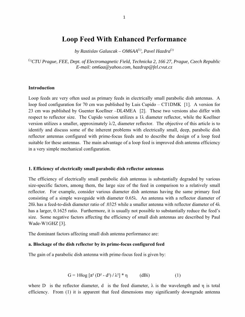
Loop Feed With Enhanced Performance by Rastislav Galuscak – OM6AA(1), Pavel Hazdra(1)
(1)CTU Prague, FEE, Dept. of Electromagnetic Field, Technicka 2, 166 27, Prague, Czech Republic E-mail: [email protected], [email protected]
Introduction
Loop feeds are very often used as primary feeds in electrically small parabolic dish antennas. A loop feed configuration for 70 cm was published by Luis Cupido – CT1DMK [1]. A version for 23 cm was published by Guenter Koellner –DL4MEA [2]. These two versions also differ with respect to reflector size. The Cupido version utilizes a 1λ diameter reflector, while the Koellner version utilizes a smaller, approximately λ/2, diameter reflector. The objective of this article is to identify and discuss some of the inherent problems with electrically small, deep, parabolic dish reflector antennas configured with prime-focus feeds and to describe the design of a loop feed suitable for these antennas. The main advantage of a loop feed is improved dish antenna efficiency in a very simple mechanical configuration.
1. Efficiency of electrically small parabolic dish reflector antennas
The efficiency of electrically small parabolic dish antennas is substantially degraded by various size-specific factors, among them, the large size of the feed in comparison to a relatively small reflector. For example, consider various diameter dish antennas having the same primary feed consisting of a simple waveguide with diameter 0.65λ. An antenna with a reflector diameter of 20λ has a feed-to-dish diameter ratio of .0325 while a smaller antenna with reflector diameter of 4λ has a larger, 0.1625 ratio. Furthermore, it is usually not possible to substantially reduce the feed’s size. Some negative factors affecting the efficiency of small dish antennas are described by Paul Wade-W1GHZ [3].
The dominant factors affecting small dish antenna performance are:
a. Blockage of the dish reflector by its prime-focus configured feed
The gain of a parabolic dish antenna with prime-focus feed is given by:
G = 10log [π² (D² - d²) / λ²] * η (dBi) (1)
where D is the reflector diameter, d is the feed diameter, λ is the wavelength and η is total efficiency. From (1) it is apparent that feed dimensions may significantly downgrade antenna
2
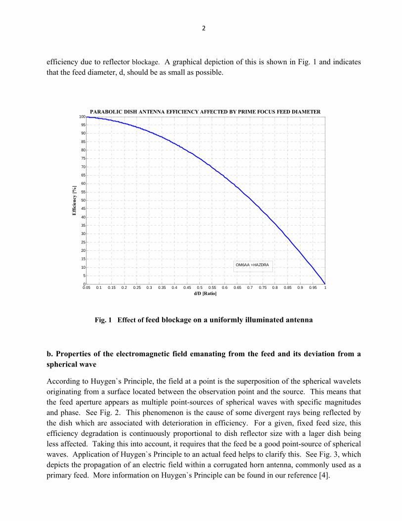
efficiency due to reflector blockage. A graphical depiction of this is shown in Fig. 1 and indicates that the feed diameter, d, should be as small as possible.
0.05 0.1 0.15 0.2 0.25 0.3 0.35 0.4 0.45 0.5 0.55 0.6 0.65 0.7 0.75 0.8 0.85 0.9 0.95 10
5
10
15
20
25
30
35
40
45
50
55
60
65
70
75
80
85
90
95
100
d/D [Ratio]
Effi
cien
cy [%
]
PARABOLIC DISH ANTENNA EFFICIENCY AFFECTED BY PRIME FOCUS FEED DIAMETER
OM6AA +HAZDRA
Fig. 1 Effect of feed blockage on a uniformly illuminated antenna
b. Properties of the electromagnetic field emanating from the feed and its deviation from a spherical wave
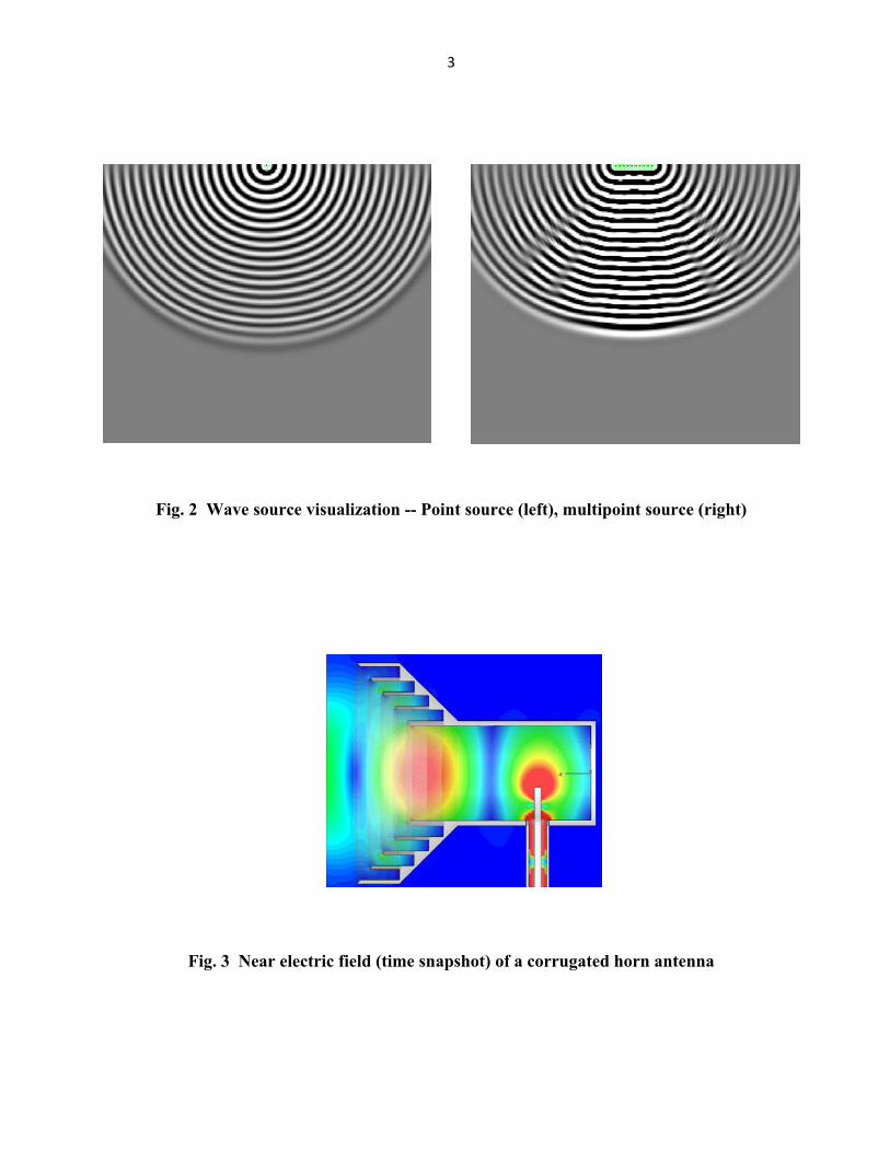
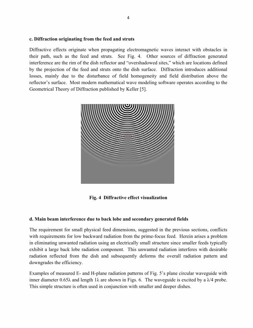
According to Huygen`s Principle, the field at a point is the superposition of the spherical wavelets originating from a surface located between the observation point and the source. This means that the feed aperture appears as multiple point-sources of spherical waves with specific magnitudes and phase. See Fig. 2. This phenomenon is the cause of some divergent rays being reflected by the dish which are associated with deterioration in efficiency. For a given, fixed feed size, this efficiency degradation is continuously proportional to dish reflector size with a lager dish being less affected. Taking this into account, it requires that the feed be a good point-source of spherical waves. Application of Huygen`s Principle to an actual feed helps to clarify this. See Fig. 3, which depicts the propagation of an electric field within a corrugated horn antenna, commonly used as a primary feed. More information on Huygen`s Principle can be found in our reference [4].
3
Fig. 2 Wave source visualization -- Point source (left), multipoint source (right)
Fig. 3 Near electric field (time snapshot) of a corrugated horn antenna
4
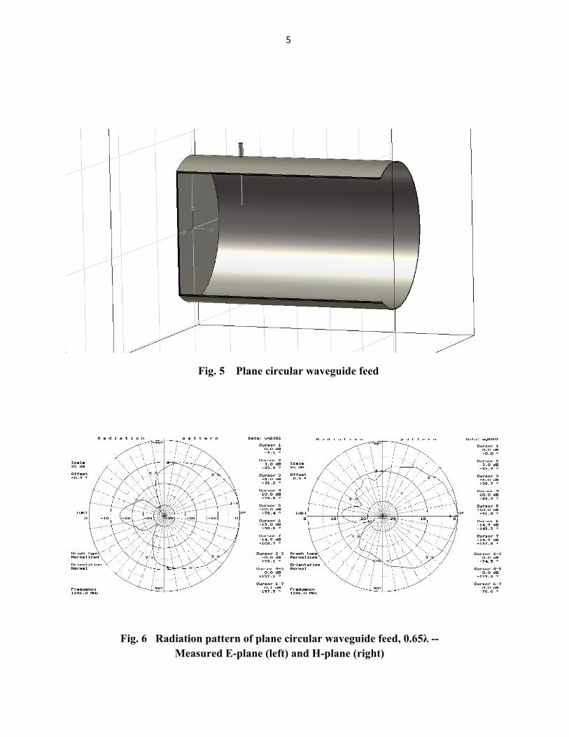
c. Diffraction originating from the feed and struts
Diffractive effects originate when propagating electromagnetic waves interact with obstacles in their path, such as the feed and struts. See Fig. 4. Other sources of diffraction generated interference are the rim of the dish reflector and “overshadowed sites,” which are locations defined by the projection of the feed and struts onto the dish surface. Diffraction introduces additional losses, mainly due to the disturbance of field homogeneity and field distribution above the reflector’s surface. Most modern mathematical wave modeling software operates according to the Geometrical Theory of Diffraction published by Keller [5].
Fig. 4 Diffractive effect visualization
d. Main beam interference due to back lobe and secondary generated fields
The requirement for small physical feed dimensions, suggested in the previous sections, conflicts with requirements for low backward radiation from the prime-focus feed. Herein arises a problem in eliminating unwanted radiation using an electrically small structure since smaller feeds typically exhibit a large back lobe radiation component. This unwanted radiation interferes with desirable radiation reflected from the dish and subsequently deforms the overall radiation pattern and downgrades the efficiency.
Examples of measured E- and H-plane radiation patterns of Fig. 5’s plane circular waveguide with inner diameter 0.65λ and length 1λ are shown in Figs. 6. The waveguide is excited by a λ/4 probe. This simple structure is often used in conjunction with smaller and deeper dishes.
5
Fig. 5 Plane circular waveguide feed
Fig. 6 Radiation pattern of plane circular waveguide feed, 0.65λ -- Measured E-plane (left) and H-plane (right)
6
The radiation pattern in Fig. 6 shows that the back lobe is suppressed by only 12 dB. The backward radiation of this feed may be further suppressed by adding a choke at the open end of the waveguide, but the tradeoff for this is a narrowed radiation pattern and increased dish blockage.
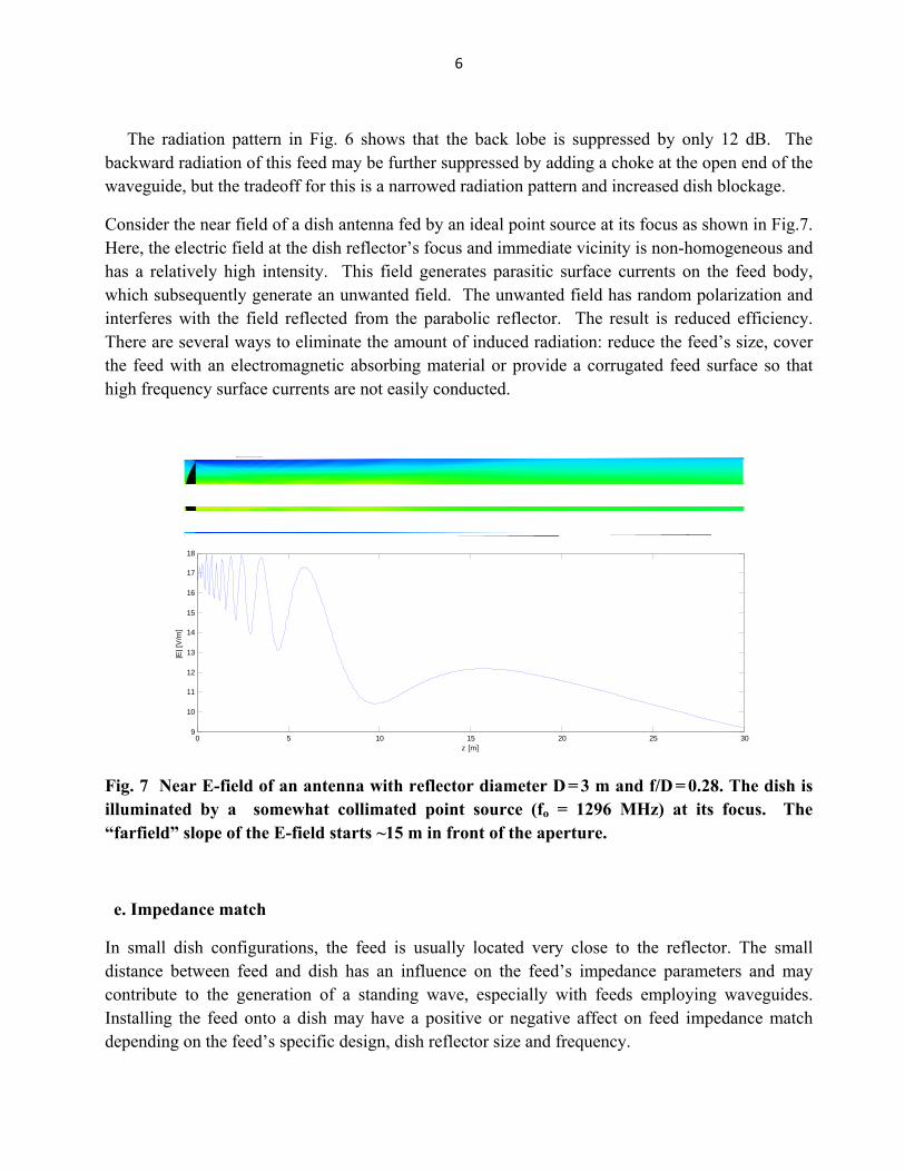
Consider the near field of a dish antenna fed by an ideal point source at its focus as shown in Fig.7. Here, the electric field at the dish reflector’s focus and immediate vicinity is non-homogeneous and has a relatively high intensity. This field generates parasitic surface currents on the feed body, which subsequently generate an unwanted field. The unwanted field has random polarization and interferes with the field reflected from the parabolic reflector. The result is reduced efficiency. There are several ways to eliminate the amount of induced radiation: reduce the feed’s size, cover the feed with an electromagnetic absorbing material or provide a corrugated feed surface so that high frequency surface currents are not easily conducted.
0 5 10 15 20 25 309
10
11
12
13
14
15
16
17
18
z [m]
|E| [
V/m
]
Fig. 7 Near E-field of an antenna with reflector diameter D = 3 m and f/D = 0.28. The dish is illuminated by a somewhat collimated point source (fo = 1296 MHz) at its focus. The “farfield” slope of the E-field starts ~15 m in front of the aperture.
e. Impedance match
In small dish configurations, the feed is usually located very close to the reflector. The small distance between feed and dish has an influence on the feed’s impedance parameters and may contribute to the generation of a standing wave, especially with feeds employing waveguides. Installing the feed onto a dish may have a positive or negative affect on feed impedance match depending on the feed’s specific design, dish reflector size and frequency.
7
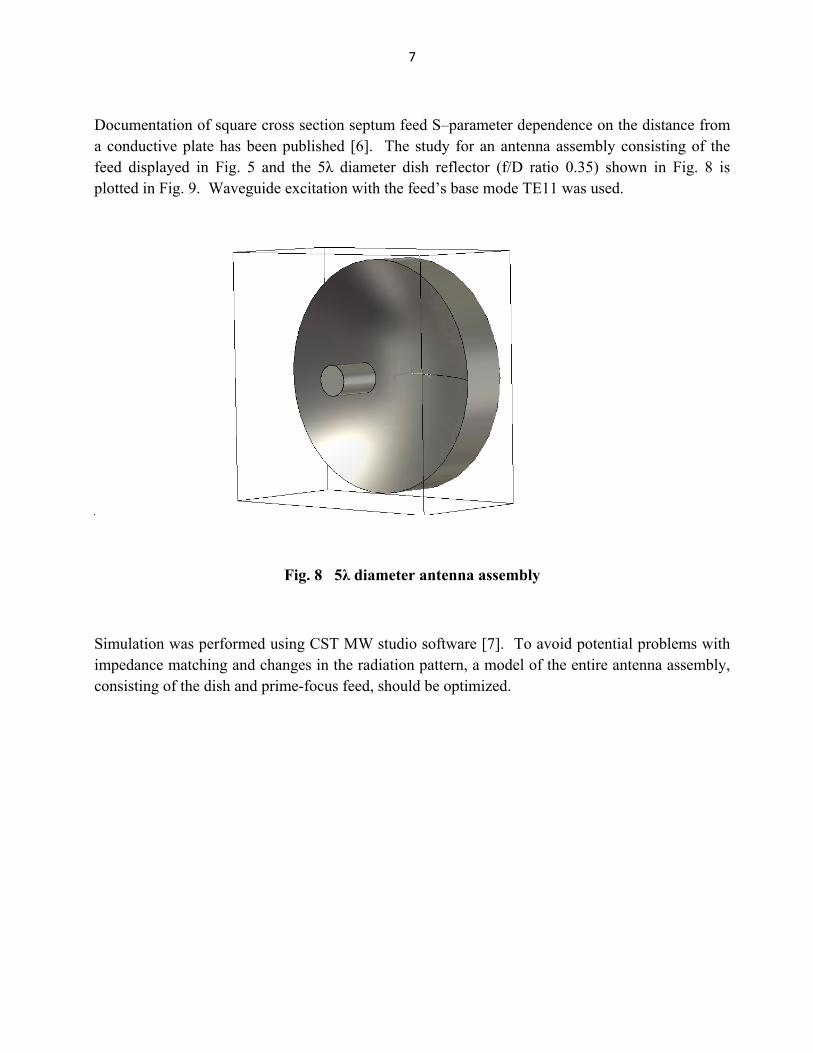
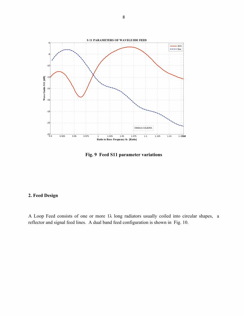
Documentation of square cross section septum feed S–parameter dependence on the distance from a conductive plate has been published [6]. The study for an antenna assembly consisting of the feed displayed in Fig. 5 and the 5λ diameter dish reflector (f/D ratio 0.35) shown in Fig. 8 is plotted in Fig. 9. Waveguide excitation with the feed’s base mode TE11 was used.
Fig. 8 5λ diameter antenna assembly
Simulation was performed using CST MW studio software [7]. To avoid potential problems with impedance matching and changes in the radiation pattern, a model of the entire antenna assembly, consisting of the dish and prime-focus feed, should be optimized.
8
0.9 0.925 0.95 0.975 1 1.025 1.05 1.075 1.1 1.125 1.15 1.1751.181.18-22
-20
-18
-16
-14
-12
-10
-8
-6
Ratio to Base Frequency fo [Ratio]
Wav
e G
uide
S11
[dB
]S 11 PARAMETERS OF WAVEGUIDE FEED
dishfree
OM6AA+HAZDRA
Fig. 9 Feed S11 parameter variations
2. Feed Design
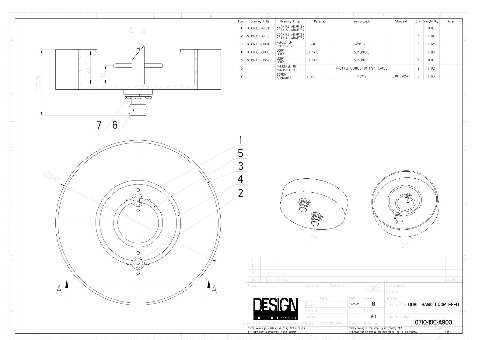
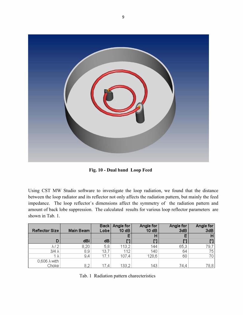
A Loop Feed consists of one or more 1λ long radiators usually coiled into circular shapes, a reflector and signal feed lines. A dual band feed configuration is shown in Fig. 10.
9
Fig. 10 - Dual band Loop Feed
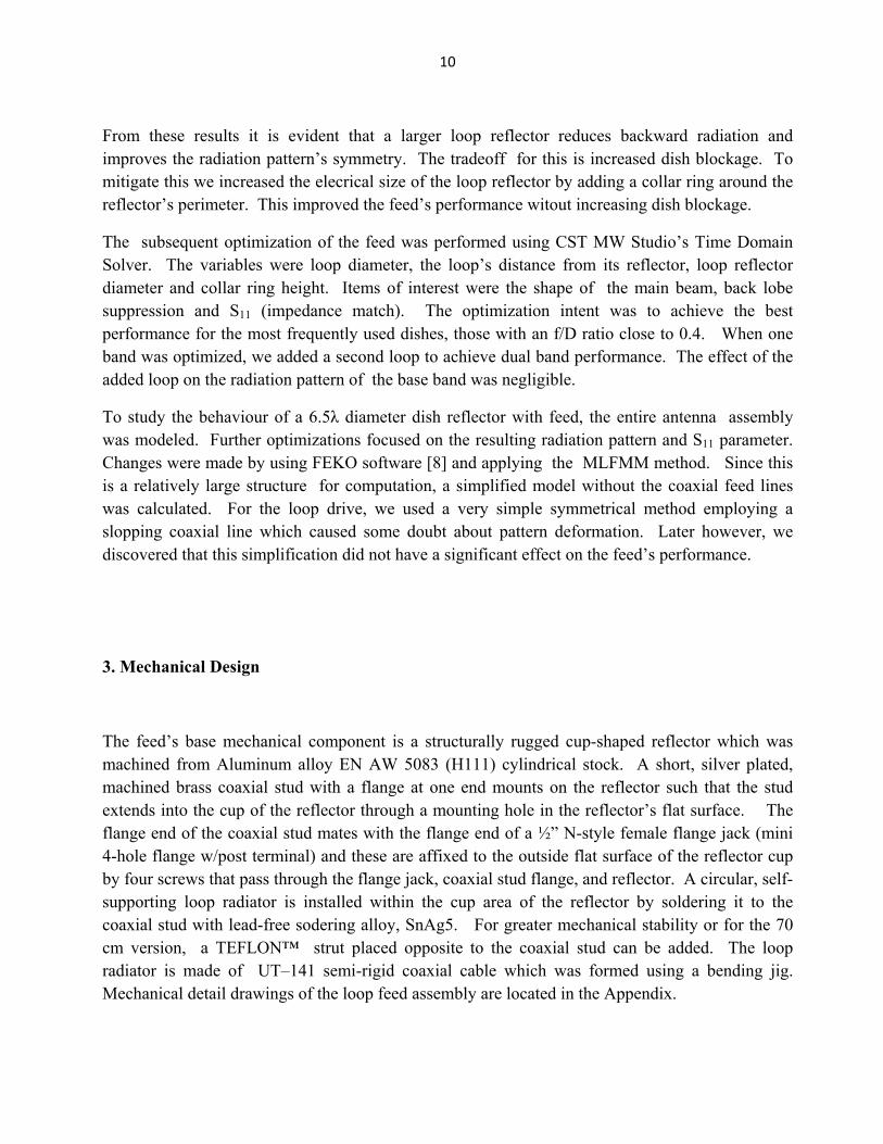
Using CST MW Studio software to investigate the loop radiation, we found that the distance between the loop radiator and its reflector not only affects the radiation pattern, but mainly the feed impedance. The loop reflector`s dimensions affect the symmetry of the radiation pattern and amount of back lobe suppression. The calculated results for various loop reflector parameters are shown in Tab. 1.
Tab. 1 Radiation pattern charecteristics
10
From these results it is evident that a larger loop reflector reduces backward radiation and improves the radiation pattern’s symmetry. The tradeoff for this is increased dish blockage. To mitigate this we increased the elecrical size of the loop reflector by adding a collar ring around the reflector’s perimeter. This improved the feed’s performance witout increasing dish blockage.
The subsequent optimization of the feed was performed using CST MW Studio’s Time Domain Solver. The variables were loop diameter, the loop’s distance from its reflector, loop reflector diameter and collar ring height. Items of interest were the shape of the main beam, back lobe suppression and S11 (impedance match). The optimization intent was to achieve the best performance for the most frequently used dishes, those with an f/D ratio close to 0.4. When one band was optimized, we added a second loop to achieve dual band performance. The effect of the added loop on the radiation pattern of the base band was negligible.
To study the behaviour of a 6.5λ diameter dish reflector with feed, the entire antenna assembly was modeled. Further optimizations focused on the resulting radiation pattern and S11 parameter. Changes were made by using FEKO software [8] and applying the MLFMM method. Since this is a relatively large structure for computation, a simplified model without the coaxial feed lines was calculated. For the loop drive, we used a very simple symmetrical method employing a slopping coaxial line which caused some doubt about pattern deformation. Later however, we discovered that this simplification did not have a significant effect on the feed’s performance.
3. Mechanical Design
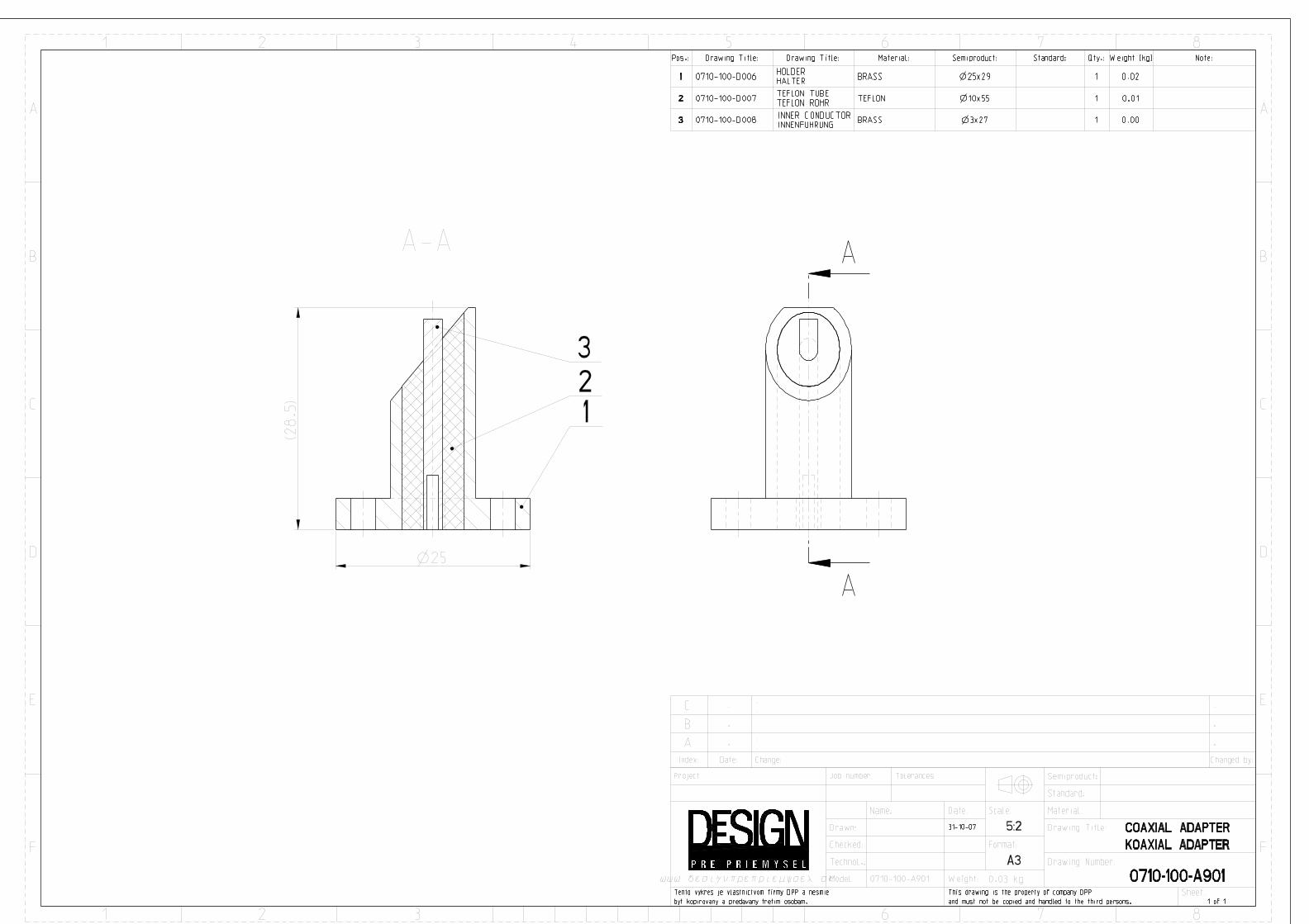
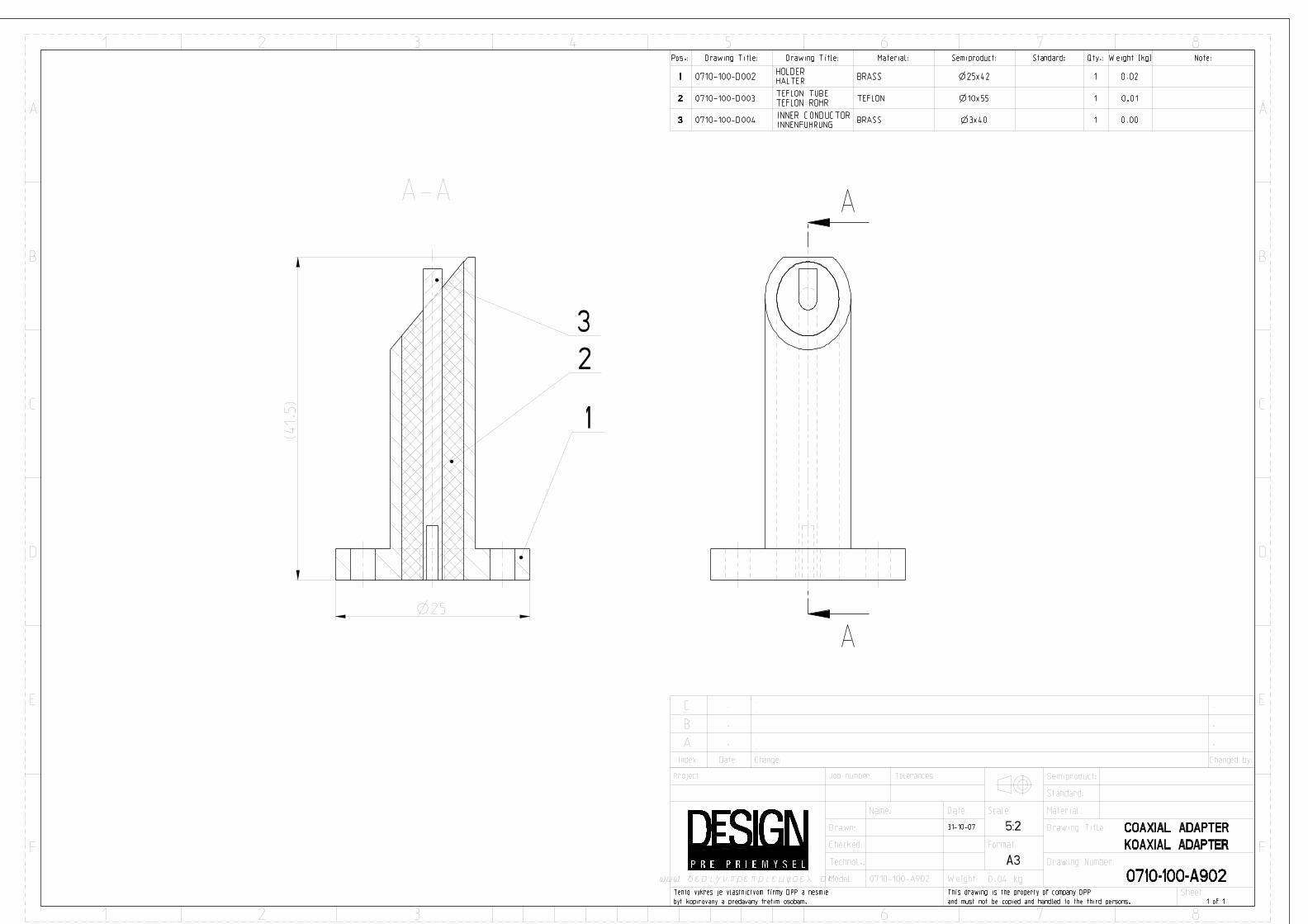
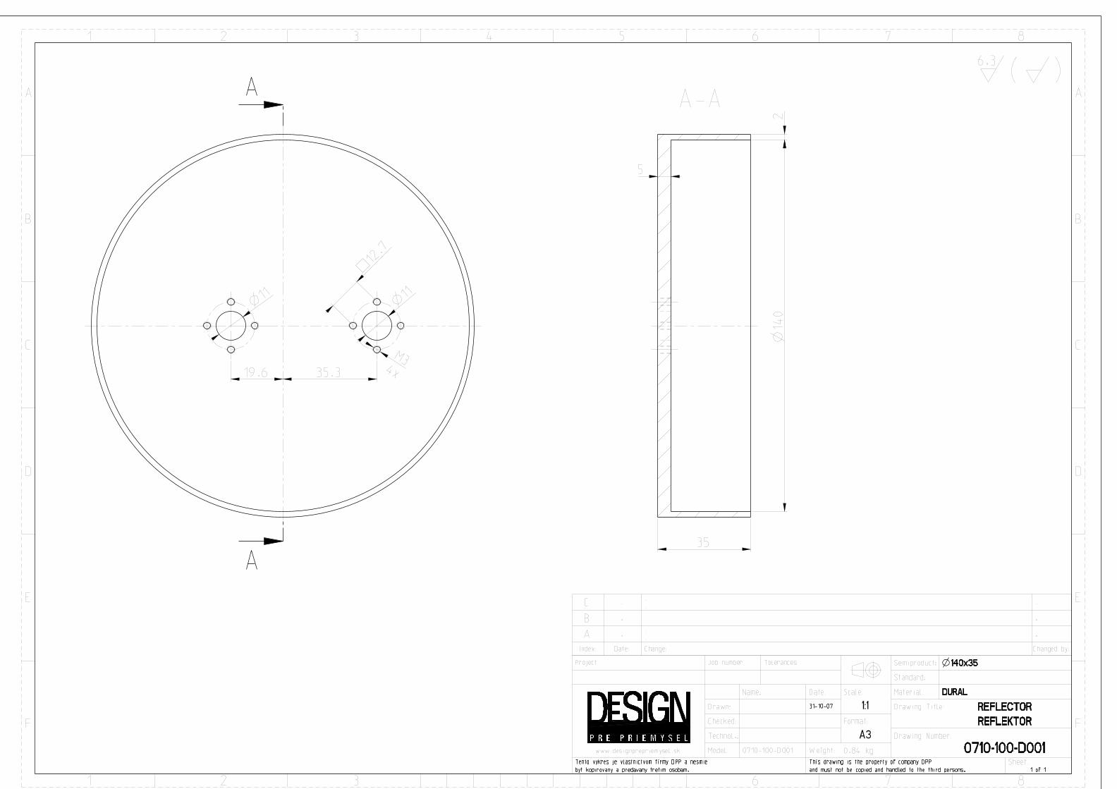
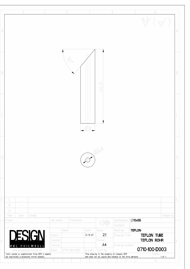
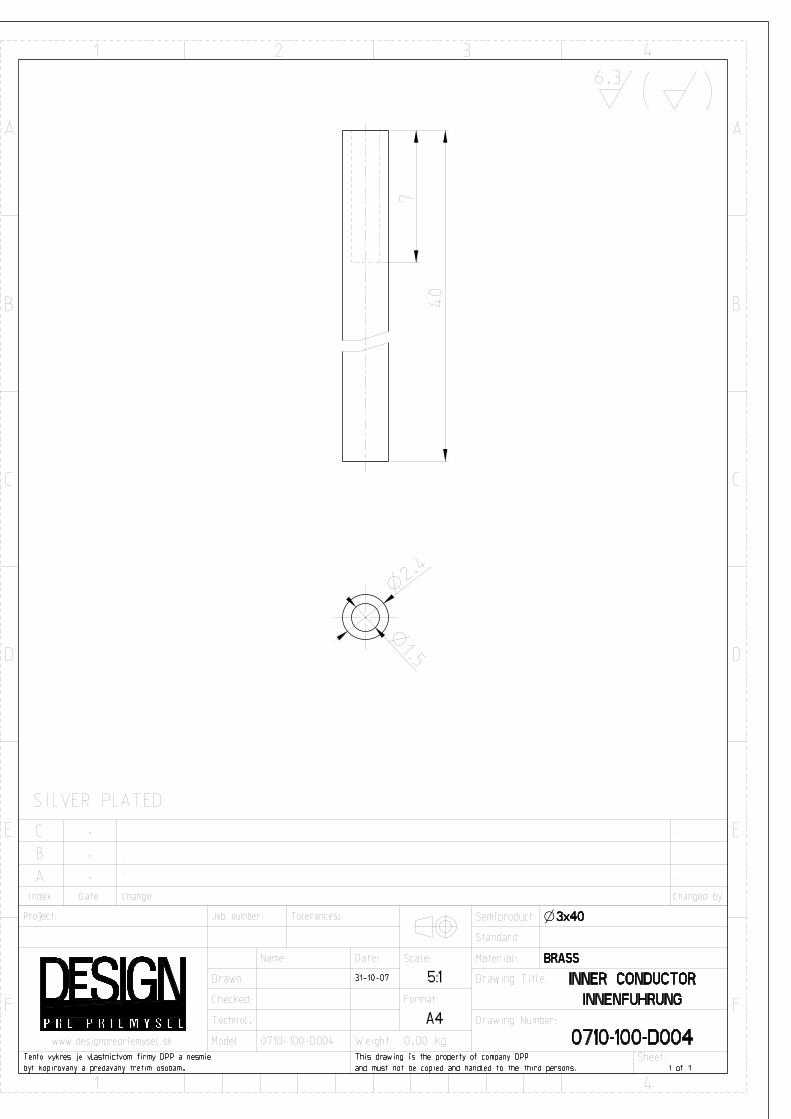
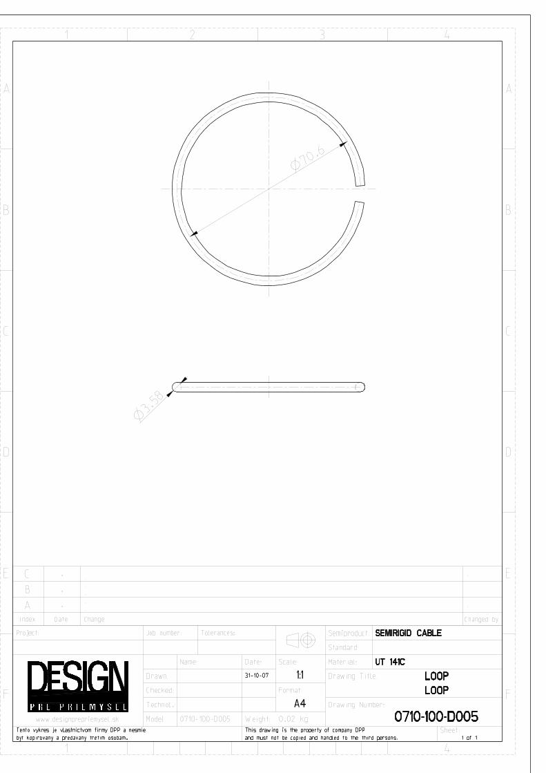
The feed’s base mechanical component is a structurally rugged cup-shaped reflector which was machined from Aluminum alloy EN AW 5083 (H111) cylindrical stock. A short, silver plated, machined brass coaxial stud with a flange at one end mounts on the reflector such that the stud extends into the cup of the reflector through a mounting hole in the reflector’s flat surface. The flange end of the coaxial stud mates with the flange end of a ½” N-style female flange jack (mini 4-hole flange w/post terminal) and these are affixed to the outside flat surface of the reflector cup by four screws that pass through the flange jack, coaxial stud flange, and reflector. A circular, self-supporting loop radiator is installed within the cup area of the reflector by soldering it to the coaxial stud with lead-free sodering alloy, SnAg5. For greater mechanical stability or for the 70 cm version, a TEFLON™ strut placed opposite to the coaxial stud can be added. The loop radiator is made of UT–141 semi-rigid coaxial cable which was formed using a bending jig. Mechanical detail drawings of the loop feed assembly are located in the Appendix.
11
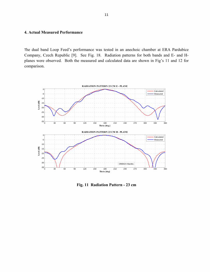
4. Actual Measured Performance
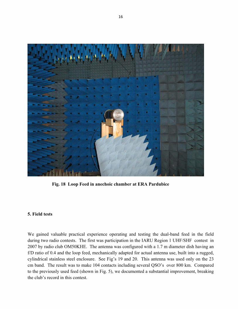
The dual band Loop Feed’s performance was tested in an anechoic chamber at ERA Pardubice Company, Czech Republic [9]. See Fig. 18. Radiation patterns for both bands and E- and H-planes were observed. Both the measured and calculated data are shown in Fig’s 11 and 12 for comparison.
0 30 60 90 120 150 180 210 240 270 300 330 360-35
-30
-25
-20
-15
-10
-5
0
Theta [deg.]
Leve
l [dB
]
RADIATION PATTERN 23 CM E - PLANE
0 30 60 90 120 150 180 210 240 270 300 330 360-35
-30
-25
-20
-15
-10
-5
0
Theta [deg]
Leve
l [dB
]
RADIATION PATTERN 23 CM H - PLANE
CalculatedMeasured
CalculatedMeasured
OM6AA+Hazdra
Fig. 11 Radiation Pattern - 23 cm
12
0 30 60 90 120 150 180 210 240 270 300 330 360-40
-35
-30
-25
-20
-15
-10
-5
01
Theta [deg.]
Leve
l [dB
]
RADIATION PATTERN 13 CM E - PLANE
0 30 60 90 120 150 180 210 240 270 300 330 360-40
-35
-30
-25
-20
-15
-10
-5
01
Theta [deg.]
Leve
l [dB
]
RADIATION PATTERN 13 CM H - PLANE
CalculatedMeasured
CalculatedMeasured
OM6AA+Hazdra
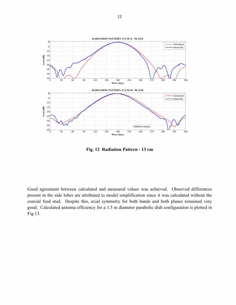
Fig. 12 Radiation Pattern - 13 cm
Good agreement between calculated and measured values was achieved. Observed differences present in the side lobes are attributed to model simplification since it was calculated without the coaxial feed stud. Despite this, axial symmetry for both bands and both planes remained very good. Calculated antenna efficiency for a 1.5 m diameter parabolic dish configuration is plotted in Fig.13.
13
0.25 0.275 0.3 0.325 0.35 0.375 0.4 0.425 0.45 0.475 0.50
10
20
30
40
50
60
70
80
90
100
Parabolic Dish f/D
Para
bolic
Dish
Effi
cien
cy %
Dish Antenna Efficiency
23 cm13 cm
Dish Diameter 1.5 m
OM6AA + HAZDRA
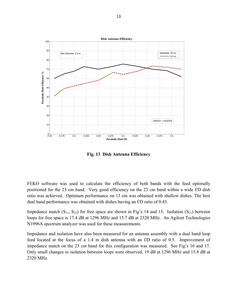
Fig. 13 Dish Antenna Efficiency
FEKO software was used to calculate the efficiency of both bands with the feed optimally positioned for the 23 cm band. Very good efficiency on the 23 cm band within a wide f/D dish ratio was achieved. Optimum performance on 13 cm was obtained with shallow dishes. The best dual band performance was obtained with dishes having an f/D ratio of 0.45.
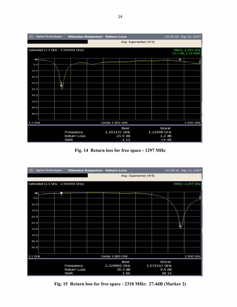
Impedance match (S11, S22) for free space are shown in Fig’s 14 and 15. Isolation (S21) between loops for free space is 17.4 dB at 1296 MHz and 15.7 dB at 2320 MHz. An Agilent Technologies N1996A spectrum analyzer was used for these measurements.
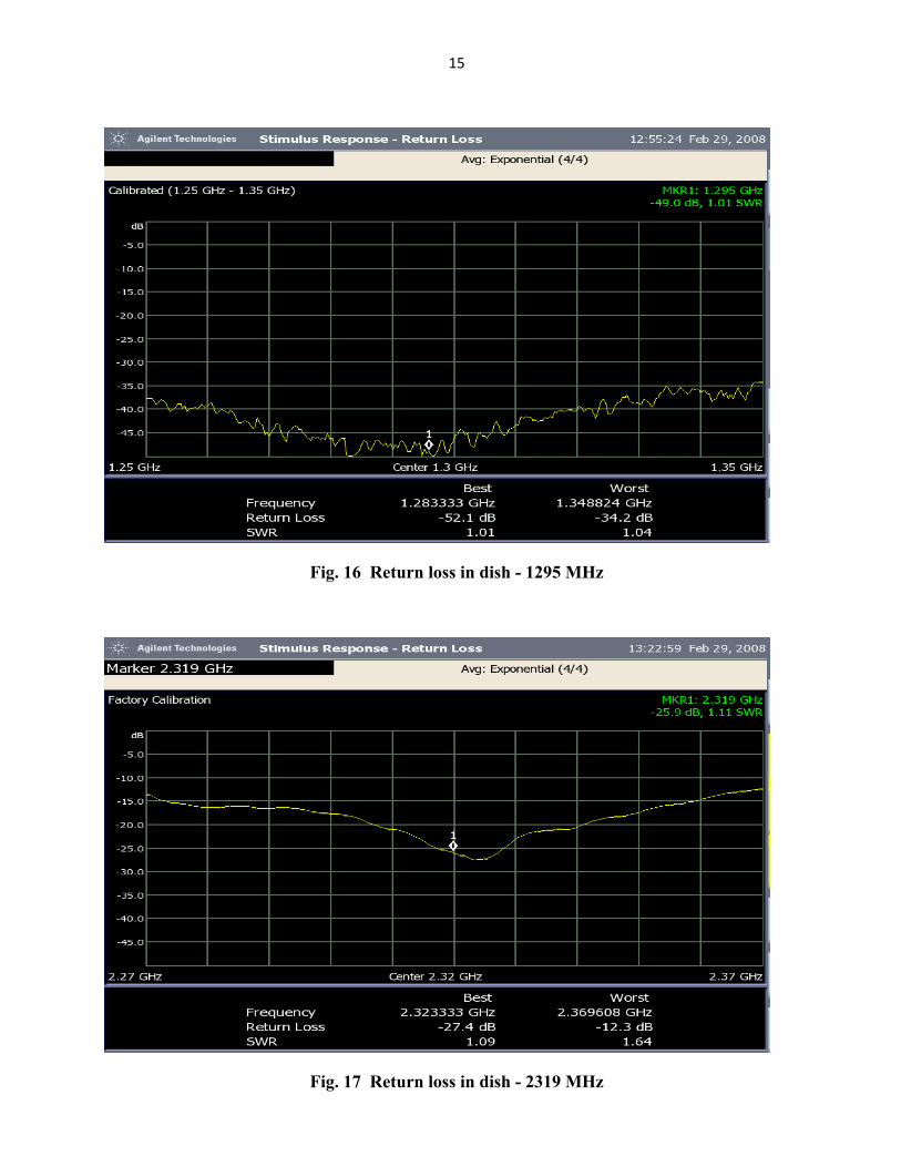
Impedance and isolation have also been measured for an antenna assembly with a dual band loop feed located at the focus of a 1.4 m dish antenna with an f/D ratio of 0.5. Improvement of impedance match on the 23 cm band for this configuration was measured. See Fig’s 16 and 17. Only small changes in isolation between loops were observed, 19 dB at 1296 MHz and 15.8 dB at 2320 MHz.
14
Fig. 14 Return loss for free space - 1297 MHz
Fig. 15 Return loss for free space - 2318 MHz: 27.4dB (Marker 2)
15
Fig. 16 Return loss in dish - 1295 MHz
Fig. 17 Return loss in dish - 2319 MHz
16
Fig. 18 Loop Feed in anechoic chamber at ERA Pardubice
5. Field tests
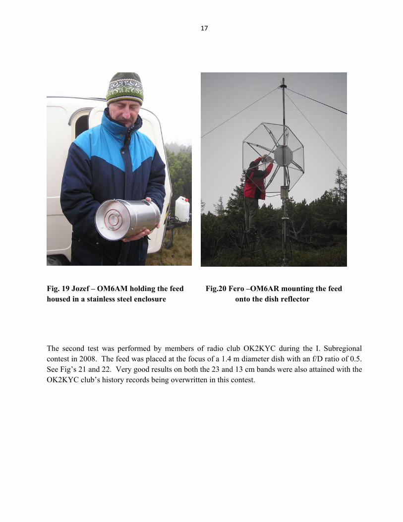
We gained valuable practical experience operating and testing the dual-band feed in the field during two radio contests. The first was participation in the IARU Region 1 UHF/SHF contest in 2007 by radio club OM50KHE. The antenna was configured with a 1.7 m diameter dish having an f/D ratio of 0.4 and the loop feed, mechanically adapted for actual antenna use, built into a rugged, cylindrical stainless steel enclosure. See Fig’s 19 and 20. This antenna was used only on the 23 cm band. The result was to make 104 contacts including several QSO’s over 800 km. Compared to the previously used feed (shown in Fig. 5), we documented a substantial improvement, breaking the club’s record in this contest.
17
Fig. 19 Jozef – OM6AM holding the feed Fig.20 Fero –OM6AR mounting the feed housed in a stainless steel enclosure onto the dish reflector
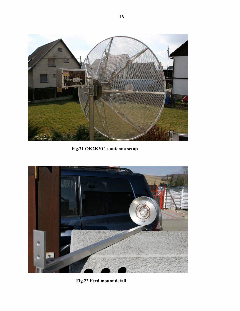
The second test was performed by members of radio club OK2KYC during the I. Subregional contest in 2008. The feed was placed at the focus of a 1.4 m diameter dish with an f/D ratio of 0.5. See Fig’s 21 and 22. Very good results on both the 23 and 13 cm bands were also attained with the OK2KYC club’s history records being overwritten in this contest.
18
Fig.21 OK2KYC`s antenna setup
Fig.22 Feed mount detail
19
Summary and conclusions
The Loop Feed represents a simple, highly efficient, easy-to-make feed variant for prime-focus-based dish antennas. A Loop Feed is easily adapted to various f/D dish ratios by changing the loop reflector’s size and the feed dimensions may be scaled by frequency to adapt it to 70 cm or higher bands. Adding a second loop enables multi-band capability. The mechanical configuration is very rugged, compact and easily allows protection of the loop wires by using a dielectric cover over the feed’s aperture. Our Loop Feed can handle very high power, limited only by its “N” style connectors. Since isolation between loops is relatively low, a high-power switching relay with good isolation must be used to protect the receiver in high-power, multi-band applications.
Acknowledgements
The authors wish to acknowledge the help of Vitezslav Krcmar and Peter Kasparek – OK2ULQ for performing feed measurements, Vladimir Petrzilka – OK1VPZ, for fabricating mechanical parts and Robert Valenta for his technical and language assistance.
References
[1] Cupido, Luis - CT1DMK; “70cm Deep Dish Feed” DUBUS, 2/2002
[2] Koellner, Guenter - DL4MEA; “Parabolic Dish Ring Feed” http://www.qsl.net/dl4mea/ringfeed.htm
[3]Wade,Paul-W1GHZ;“Multiple ReflectorDish Antennas” http://www.w1ghz.org/antbook/conf/Multiple_reflector_antennas.pdf
[4] Ishimaru, Akira; “Electromagnetic Wave Propagation Radiation and Scatering” Prentice Hall, New Jersey, 1991. ISBN 0-13-249053-6
[5] Keller J. B.; “Geometrical theory of diffraction,” J. Opt. Soc. Of America 52, 116-130 (1962)
[6] Galuscak, Rastislav- OM6AA; “Septum Feed Revisited” DUBUS 4/2004
[7] Computer Simulation Technology web site: www.cst.de
[8] FEKO EM systems-Software & SS.A. (Pty) Ltd, website: www.feko.info
[9] ERA Pardubice, webside: www.era.cz