Embed Size (px)
Citation preview
Low Power Microarchitecture with Instruction Reuse
Frederico PratasINESC-ID/IST
Rua Alves Redol, 9, 1000-029Lisboa, Portugal
Georgi GaydadjievCE Lab/TU Delft
Mekelweg 4, 2628 CDDelft, The Netherlands
Mladen BerekovicTU Braunschweig
Braunschweig, [email protected]
bs.deLeonel Sousa
INESC-ID/ISTRua Alves Redol, 9, 1000-029
Lisboa, [email protected]
Stefanos KaxirasUniversity of Patras
Patras, [email protected]
ABSTRACTPower consumption has become a very important metric andchallenging research topic in the design of microprocessors inthe recent years. The goal of this work is to improve powerefficiency of superscalar processors through instruction reuseat the execution stage. This paper proposes a new methodfor reusing instructions when they compose small loops: theloop’s instructions are first buffered in the Reorder Bufferand reused afterwards without the need for dynamically un-rolling the loop, as commonly implemented by the tradi-tional instruction reusing techniques. The proposed methodis implemented with the introduction of two new auxiliaryhardware structures in a typical superscalar microarchitec-ture: a Finite State Machine (FSM), used to detect thereusable loops; and a Log used to store the renaming datafor each instruction when the loop is “unrolled”. In order toevaluate the proposed method we modified the sim-outordertool from Simplescalar v3.0 for the PISA, and Wattch v1.02Power Performance simulators. Several different configura-tions and benchmarks have been used during the simula-tions. The obtained results show that by implementing thisnew method in a superscalar microarchitecture, the powerefficiency can be improved without significantly affectingneither the performance nor the cost.
Categories and Subject DescriptorsC.1.1 [Processor Architectures]: Single Data Stream Ar-chitectures—RISC/CISC, VLIW architectures
General TermsDesign, Performance
Permission to make digital or hard copies of all or part of this work forpersonal or classroom use is granted without fee provided that copies arenot made or distributed for profit or commercial advantage and that copiesbear this notice and the full citation on the first page. To copy otherwise, torepublish, to post on servers or to redistribute to lists, requires prior specificpermission and/or a fee.CF’08, May 5–7, 2008, Ischia, Italy.Copyright 2008 ACM 978-1-60558-077-7/08/05 ...$5.00.
KeywordsPower Reduction, Superscalar Processor, Loop Reusing Tech-nique, Reorder Buffer Optimization.
1. INTRODUCTIONThree decades of history of microprocessors report truly
remarkable technological advances in the computer indus-try. This evolution closely followed the well-known GordonMoore Law [8]. Aiming ever-faster microprocessors, sev-eral strategies that focus in exploiting Instruction-Level Par-alelism (ILP) have been adopted, namely: deeper pipelining,multiple execution units, wider fetching mechanisms andspeculative execution have been used in the microprocessorsdesign [4]. Today’s superscalar processor microarchitecturesprove the effort that has been done to exploit ILP. Due tothis evolution, power consumption has also become one ofthe most important parameters in the design of such com-plex systems [13].
Nowadays, instruction reuse (IR) techniques are used toimprove the power efficiency and ILP in superscalar microar-chitectures. Reuse methods have been developed at differ-ent stages: at the fetch/decode stages, for instance throughtrace caches [10] and dynamic instruction reuse [14]; andat the execution stage, using mechanisms such as the issuequeue buffering [6], the trace reuse [18] and the executioncache [16]. All of these methods reuse instructions that havebeen previously fetched from the instruction cache and thatare still available in the processors core, in order to pre-vent the fetch and/or the passage of instructions throughprocessing stages; for instance by reusing instructions at theexecution stage, the front-end of the processor can be gated-off. Therefore, such methods can improve power efficiencyby exploiting repeated operations during the execution ofprograms, like the frequent existence of loops in real pro-grams.
This paper proposes an enhanced microarchitecture whichimplements a new IR method at the execution stage toreduce the power consumption in a superscalar processor.Besides reducing the number of accesses to the memory,the proposed method also decreases the power consump-tion by reusing the instructions directly from the reorderbuffer (ROB) and thus avoiding the flow of redundant datain the ROB by preventing explicit unrolling of simple dy-namic loops with a single control path. To implement the
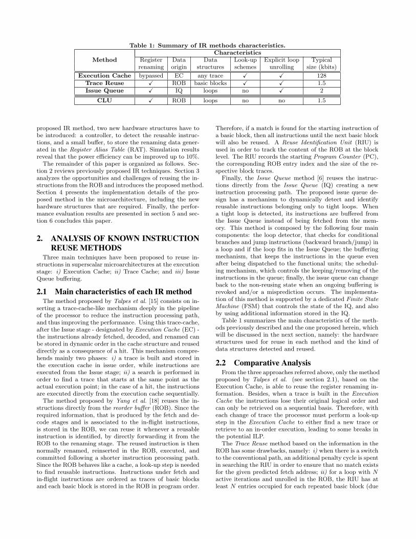
Table 1: Summary of IR methods characteristics.
MethodCharacteristics
Register Data Data Look-up Explicit loop Typicalrenaming origin structures schemes unrolling size (kbits)
Execution Cache bypassed EC any trace X X 128Trace Reuse X ROB basic blocks X X 1.5Issue Queue X IQ loops no X 2
CLU X ROB loops no no 1.5
proposed IR method, two new hardware structures have tobe introduced: a controller, to detect the reusable instruc-tions, and a small buffer, to store the renaming data gener-ated in the Register Alias Table (RAT). Simulation resultsreveal that the power efficiency can be improved up to 10%.
The remainder of this paper is organized as follows. Sec-tion 2 reviews previously proposed IR techniques. Section 3analyzes the opportunities and challenges of reusing the in-structions from the ROB and introduces the proposed method.Section 4 presents the implementation details of the pro-posed method in the microarchitecture, including the newhardware structures that are required. Finally, the perfor-mance evaluation results are presented in section 5 and sec-tion 6 concludes this paper.
2. ANALYSIS OF KNOWN INSTRUCTIONREUSE METHODS
Three main techniques have been proposed to reuse in-structions in superscalar microarchitectures at the executionstage: i) Execution Cache; ii) Trace Cache; and iii) IssueQueue buffering.
2.1 Main characteristics of each IR methodThe method proposed by Talpes et al. [15] consists on in-
serting a trace-cache-like mechanism deeply in the pipelineof the processor to reduce the instruction processing path,and thus improving the performance. Using this trace-cache,after the Issue stage - designated by Execution Cache (EC) -the instructions already fetched, decoded, and renamed canbe stored in dynamic order in the cache structure and reuseddirectly as a consequence of a hit. This mechanism compre-hends mainly two phases: i) a trace is built and stored inthe execution cache in issue order, while instructions areexecuted from the Issue stage; ii) a search is performed inorder to find a trace that starts at the same point as theactual execution point; in the case of a hit, the instructionsare executed directly from the execution cache sequentially.
The method proposed by Yang et al. [18] reuses the in-structions directly from the reorder buffer (ROB). Since therequired information, that is produced by the fetch and de-code stages and is associated to the in-flight instructions,is stored in the ROB, we can reuse it whenever a reusableinstruction is identified, by directly forwarding it from theROB to the renaming stage. The reused instruction is thennormally renamed, reinserted in the ROB, executed, andcommitted following a shorter instruction processing path.Since the ROB behaves like a cache, a look-up step is neededto find reusable instructions. Instructions under fetch andin-flight instructions are ordered as traces of basic blocksand each basic block is stored in the ROB in program order.
Therefore, if a match is found for the starting instruction ofa basic block, then all instructions until the next basic blockwill also be reused. A Reuse Identification Unit (RIU) isused in order to track the content of the ROB at the blocklevel. The RIU records the starting Program Counter (PC),the corresponding ROB entry index and the size of the re-spective block traces.
Finally, the Issue Queue method [6] reuses the instruc-tions directly from the Issue Queue (IQ) creating a newinstruction processing path. The proposed issue queue de-sign has a mechanism to dynamically detect and identifyreusable instructions belonging only to tight loops. Whena tight loop is detected, its instructions are buffered fromthe Issue Queue instead of being fetched from the mem-ory. This method is composed by the following four maincomponents: the loop detector, that checks for conditionalbranches and jump instructions (backward branch/jump) ina loop and if the loop fits in the Issue Queue; the bufferingmechanism, that keeps the instructions in the queue evenafter being dispatched to the functional units; the schedul-ing mechanism, which controls the keeping/removing of theinstructions in the queue; finally, the issue queue can changeback to the non-reusing state when an ongoing buffering isrevoked and/or a misprediction occurs. The implementa-tion of this method is supported by a dedicated Finite StateMachine (FSM) that controls the state of the IQ, and alsoby using additional information stored in the IQ.
Table 1 summarizes the main characteristics of the meth-ods previously described and the one proposed herein, whichwill be discussed in the next section, namely: the hardwarestructures used for reuse in each method and the kind ofdata structures detected and reused.
2.2 Comparative AnalysisFrom the three approaches referred above, only the method
proposed by Talpes et al. (see section 2.1), based on theExecution Cache, is able to reuse the register renaming in-formation. Besides, when a trace is built in the ExecutionCache the instructions lose their original logical order andcan only be retrieved on a sequential basis. Therefore, witheach change of trace the processor must perform a look-upstep in the Execution Cache to either find a new trace orretrieve to an in-order execution, leading to some breaks inthe potential ILP.
The Trace Reuse method based on the information in theROB has some drawbacks, namely: i) when there is a switchto the conventional path, an additional penalty cycle is spentin searching the RIU in order to ensure that no match existsfor the given predicted fetch address; ii) for a loop with Nactive iterations and unrolled in the ROB, the RIU has atleast N entries occupied for each repeated basic block (due
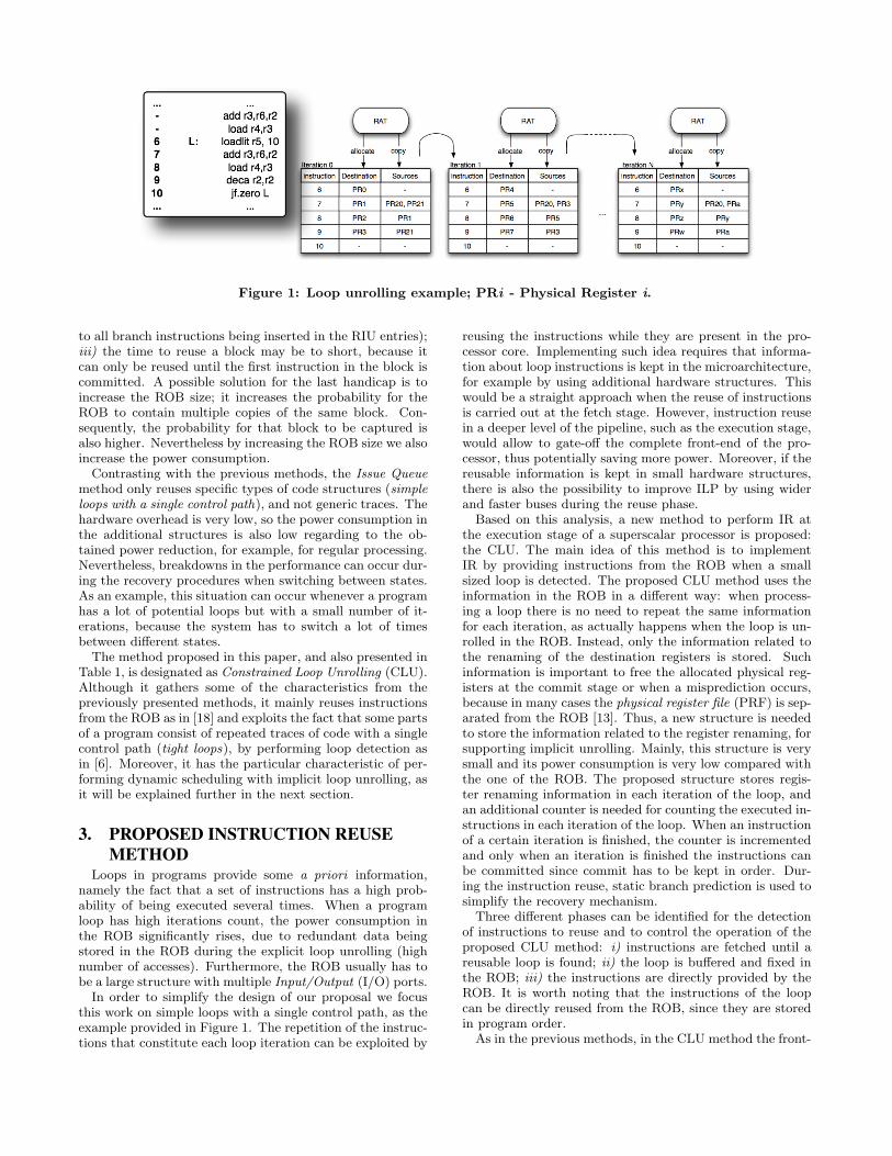
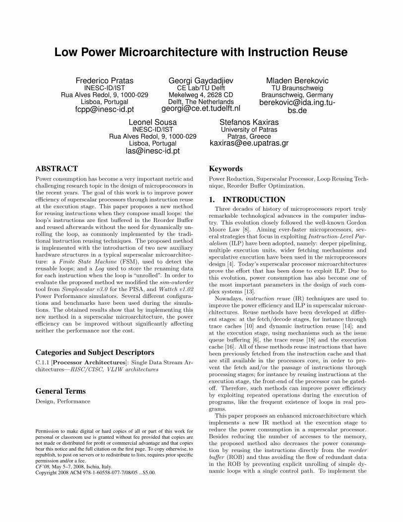
Figure 1: Loop unrolling example; PRi - Physical Register i.
to all branch instructions being inserted in the RIU entries);iii) the time to reuse a block may be to short, because itcan only be reused until the first instruction in the block iscommitted. A possible solution for the last handicap is toincrease the ROB size; it increases the probability for theROB to contain multiple copies of the same block. Con-sequently, the probability for that block to be captured isalso higher. Nevertheless by increasing the ROB size we alsoincrease the power consumption.
Contrasting with the previous methods, the Issue Queuemethod only reuses specific types of code structures (simpleloops with a single control path), and not generic traces. Thehardware overhead is very low, so the power consumption inthe additional structures is also low regarding to the ob-tained power reduction, for example, for regular processing.Nevertheless, breakdowns in the performance can occur dur-ing the recovery procedures when switching between states.As an example, this situation can occur whenever a programhas a lot of potential loops but with a small number of it-erations, because the system has to switch a lot of timesbetween different states.
The method proposed in this paper, and also presented inTable 1, is designated as Constrained Loop Unrolling (CLU).Although it gathers some of the characteristics from thepreviously presented methods, it mainly reuses instructionsfrom the ROB as in [18] and exploits the fact that some partsof a program consist of repeated traces of code with a singlecontrol path (tight loops), by performing loop detection asin [6]. Moreover, it has the particular characteristic of per-forming dynamic scheduling with implicit loop unrolling, asit will be explained further in the next section.
3. PROPOSED INSTRUCTION REUSEMETHOD
Loops in programs provide some a priori information,namely the fact that a set of instructions has a high prob-ability of being executed several times. When a programloop has high iterations count, the power consumption inthe ROB significantly rises, due to redundant data beingstored in the ROB during the explicit loop unrolling (highnumber of accesses). Furthermore, the ROB usually has tobe a large structure with multiple Input/Output (I/O) ports.
In order to simplify the design of our proposal we focusthis work on simple loops with a single control path, as theexample provided in Figure 1. The repetition of the instruc-tions that constitute each loop iteration can be exploited by
reusing the instructions while they are present in the pro-cessor core. Implementing such idea requires that informa-tion about loop instructions is kept in the microarchitecture,for example by using additional hardware structures. Thiswould be a straight approach when the reuse of instructionsis carried out at the fetch stage. However, instruction reusein a deeper level of the pipeline, such as the execution stage,would allow to gate-off the complete front-end of the pro-cessor, thus potentially saving more power. Moreover, if thereusable information is kept in small hardware structures,there is also the possibility to improve ILP by using widerand faster buses during the reuse phase.
Based on this analysis, a new method to perform IR atthe execution stage of a superscalar processor is proposed:the CLU. The main idea of this method is to implementIR by providing instructions from the ROB when a smallsized loop is detected. The proposed CLU method uses theinformation in the ROB in a different way: when process-ing a loop there is no need to repeat the same informationfor each iteration, as actually happens when the loop is un-rolled in the ROB. Instead, only the information related tothe renaming of the destination registers is stored. Suchinformation is important to free the allocated physical reg-isters at the commit stage or when a misprediction occurs,because in many cases the physical register file (PRF) is sep-arated from the ROB [13]. Thus, a new structure is neededto store the information related to the register renaming, forsupporting implicit unrolling. Mainly, this structure is verysmall and its power consumption is very low compared withthe one of the ROB. The proposed structure stores regis-ter renaming information in each iteration of the loop, andan additional counter is needed for counting the executed in-structions in each iteration of the loop. When an instructionof a certain iteration is finished, the counter is incrementedand only when an iteration is finished the instructions canbe committed since commit has to be kept in order. Dur-ing the instruction reuse, static branch prediction is used tosimplify the recovery mechanism.
Three different phases can be identified for the detectionof instructions to reuse and to control the operation of theproposed CLU method: i) instructions are fetched until areusable loop is found; ii) the loop is buffered and fixed inthe ROB; iii) the instructions are directly provided by theROB. It is worth noting that the instructions of the loopcan be directly reused from the ROB, since they are storedin program order.
As in the previous methods, in the CLU method the front-
end is decoupled from the usual instruction path when thealternative path, shorter than the main one, starts provid-ing the reusable instructions. In all the methods this is themain source of power savings, because the fetch mechanismis gated-off. Table 1 provides an overview of the main char-acteristics of the CLU method and compares them with theones of the remaining methods. In the CLU, although therename stage is not bypassed, all the unnecessary look-upschemes used in previous works are avoided. Moreover, incontrast with the IQ method described in section 2, only oneiteration of the loop is buffered at a time. During the scanphase, a potential loop is only considered when a group ofsequential instructions between two backward branches withthe same address is detected.
The ROB is a structure that consumes a relevant amountof power [7] because, as stated before, it is a large and com-plex structure accessed simultaneously in several stages ofthe processor, i.e., it needs several I/O ports and it is usedfor each and avery instruction. If the loop instructions arenot inserted in the ROB during the reuse phase, i.e., theloop is not unrolled inside the ROB, the number of accessesto the ROB is reduced and consequently the overall powerconsumption. Moreover, to implement this process we donot need to store the redundant information mentioned be-fore, but only the renamed destination register in a smallstructure, as will be explained in the following section.
4. INTEGRATION OF THE PROPOSEDCLU METHOD IN THEMICROARCHITECTURE
4.1 MicroarchitectureThe microarchitecture has to be modified, in order to sup-
port the proposed CLU instruction reuse method. The fol-lowing mechanisms have to be implemented in the super-scalar microarchitecture: i) loop detection, to detect a loopfetched from the memory and activate the reuse method; ii)loop buffering, to buffer the loop in the ROB before it can bereused; iii) loop reuse, which should enable the Log struc-ture (docked to the ROB) to start storing the informationneeded and to unroll the loop.
Therefore, two structures are introduced in the typicalsuperscalar microarchitecture to support these mechanisms:the Log and the Small Loop Finder (SLF), as shown in theblock-diagram presented in Figure 2. The SLF implementsan FSM that controls the loop detection, the loop buffer-ing and the loop reuse. The Log structure is a buffer wherethe instruction’s renaming information is stored during loopreuse, i.e., it keeps track of the physical registers allocatedin each loop iteration. In this case, the registers used in aspecific iteration can only be freed and the correspondinginstructions committed if the iteration was correctly exe-cuted (a misprediction did not occur) and all the previousiterations were committed.
The recovery misprediction mechanism has to be modi-fied. In case of a misprediction the reuse mechanism has toproceed as follows:
• the registers allocated for the instructions after themispredicted branch are freed and the respective fieldsin the Log are invalidated; when a misprediction occurssome instructions are still in execution and will arrive
Figure 2: Microarchitecture with the CLU method.
later at the write-back stage. A tag is used to validatethis instructions;
• the valid instructions still inside the Log are executedand committed normally;
• the FSM controlling the loop detection does not inserta new loop in the Log, while instructions from a pre-vious loop are in use to guarantee that the old loopfinishes correctly;
• when a Log reaches the last iteration, the Reused fieldsin the ROB are reset and the FSM can introduce a newloop.
4.2 The Finite State MachineThe identification of small loops is accomplished by a de-
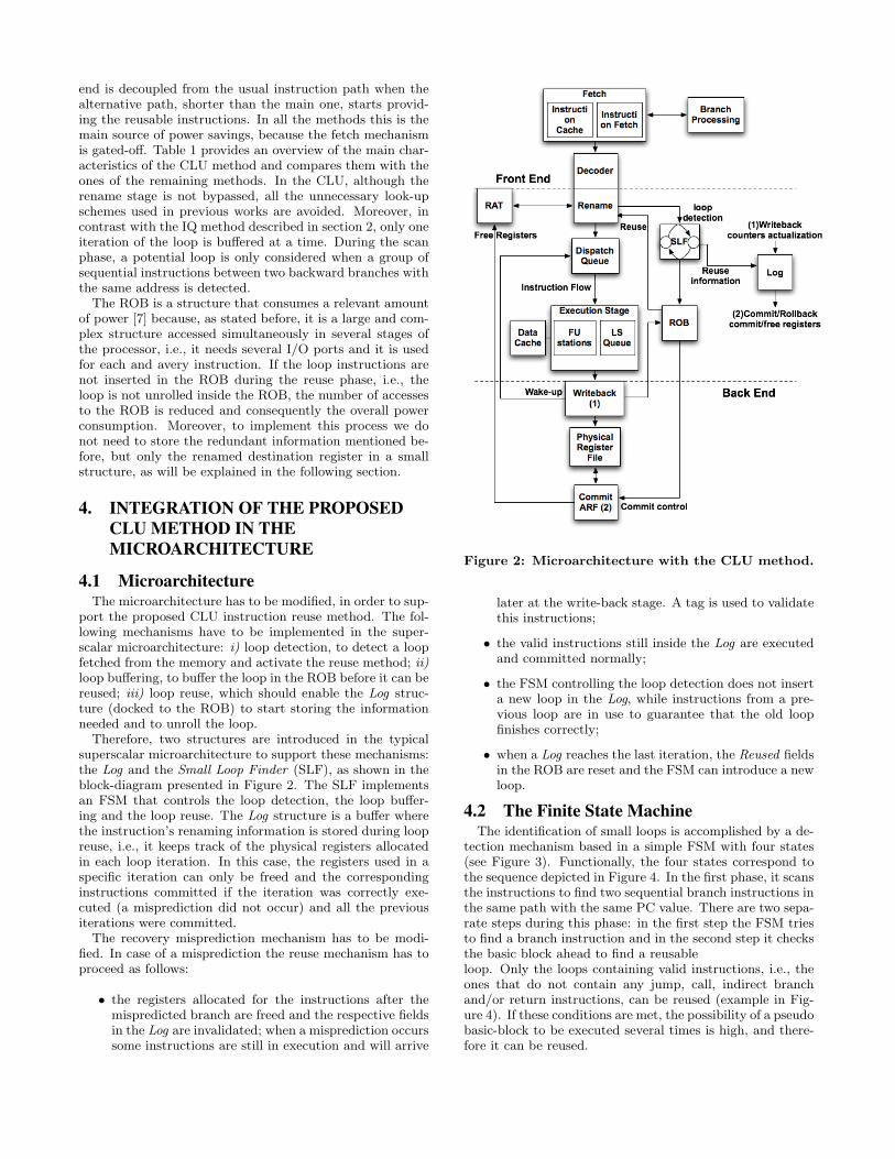
tection mechanism based in a simple FSM with four states(see Figure 3). Functionally, the four states correspond tothe sequence depicted in Figure 4. In the first phase, it scansthe instructions to find two sequential branch instructions inthe same path with the same PC value. There are two sepa-rate steps during this phase: in the first step the FSM triesto find a branch instruction and in the second step it checksthe basic block ahead to find a reusableloop. Only the loops containing valid instructions, i.e., theones that do not contain any jump, call, indirect branchand/or return instructions, can be reused (example in Fig-ure 4). If these conditions are met, the possibility of a pseudobasic-block to be executed several times is high, and there-fore it can be reused.
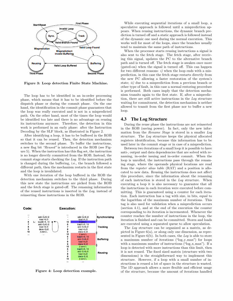
Figure 3: Loop detection Finite State Machine.
The loop has to be identified in an in-order processingphase, which means that it has to be identified before thedispatch phase or during the commit phase. On the onehand, the identification in the commit phase guarantees thatthe loop was really executed and is not in a mispredictedpath. On the other hand, most of the times the loop wouldbe identified too late and there is no advantage on reusingits instructions anymore. Therefore, the detection in thiswork is performed in an early phase: after the InstructionDecoding by the SLF block, as illustrated in Figure 2.
After identifying a loop, it has to be buffered in the ROBso that it can be reused. Then, the detection mechanismswitches to the second phase. To buffer the instructions,a new flag bit “Reused” is introduced in the ROB (see Fig-ure 5). When the instruction has this flag set, the instructionis no longer directly committed from the ROB. Instead, thecommit stage starts checking the Log. If the instruction pathis changed during the buffering, i.e., the branch followed adifferent path, then the mechanism restarts in the first stateand the loop is invalidated.
With one iteration of the loop buffered in the ROB thedetection mechanism switches to the third phase. Duringthis new state the instructions are picked from the ROBand the fetch stage is gated-off. The renaming informationof the reused instructions is inserted in the Log, instead ofreinserting these instructions in the ROB.
Figure 4: Loop detection example.
While executing sequential iterations of a small loop, aspeculative approach is followed until a misprediction ap-pears. When reusing instructions, the dynamic branch pre-diction is turned off and a static approach is followed insteadof the dynamic one used during the normal execution. Thisworks well for most of the loops, since the branches usuallytend to maintain the same path of instructions.
When the processor starts reusing instructions a signal isalso sent to the fetch stage. The fetch stage, after receiv-ing this signal, updates the PC to the alternative branchpath and is turned off. The fetch stage is awaken once more(gated-on) when the signal is turned off. This can happenfor two different reasons: i) when the loop ends with a mis-prediction, in this case the fetch stage restarts directly fromthe new PC allowing a faster restoration of the system’sstate; ii) due to a misprediction from a previous branch orother type of fault, in this case a normal restoring procedureis performed. Both cases imply that the detection mecha-nism transits again to the first state. If, after a mispredic-tion, there are still active instructions in the Log structurewaiting for commitment, the detection mechanism is neitherallowed to transit from the first phase nor to buffer a newloop.
4.3 The Log StructureDuring the reuse phase the instructions are not reinserted
in the ROB (saving power). In fact, only the new infor-mation from the Rename Stage is stored in a smaller Logstructure. The Log structure keeps the physical allocatedregisters identification, because this information has to beused later in the commit stage or in case of a misprediction.
Between two iterations of a small loop it is possible to haveanti-, output and data dependencies that are solved with re-naming, in-order issuing and in-order commit. When theloop is unrolled, the instructions pass through the renam-ing stage, where the operands physical locations are readfrom the register alias table (RAT) and a position is allo-cated to new data. Reusing the instructions does not affectthis procedure, since the information about the renamingof each instruction is stored in the Log structure. Whenexecuting a loop it is also necessary to guarantee that allthe instructions in each iteration were executed before com-mitting. This is guaranteed using a counter for each itera-tion. Each instruction has a tag with size, in bits, equal tothe logarithm of the maximum number of iterations. Thistag is also used for validation when a misprediction occurs(section 4.1), and at the end of the execution the countercorresponding to its iteration is incremented. Whenever thecounter reaches the number of instructions in the loop, theiteration is finished and can be committed. Stores and loadsare executed using a separated queue to allow speculation.
The Log structure can be organized as a matrix, as de-picted in Figure 6(a), or along only one dimension, as repre-sented in Figure 6(b). In both cases, the Log is able to storea maximum number of iterations (“log y max”) for loopswith a maximum number of instructions (“log x max”). If aloop is detected with more instructions than this limit, thenit is not reused. The fixed sized matrix (structure with twodimensions) is the straightforward way to implement thisstructure. However, if a loop with a small number of in-structions is reused a lot of space in the structure is wasted.The 1D approach allows a more flexible and efficient usageof the structure, because the amount of iterations handled
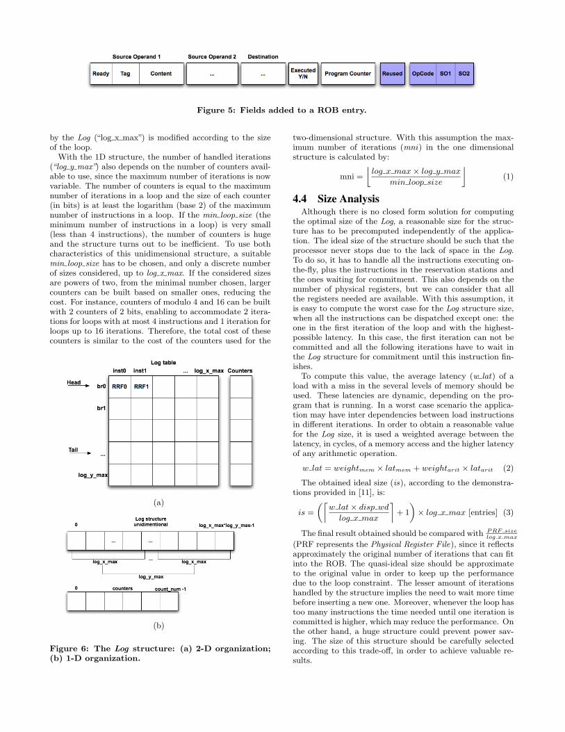
Figure 5: Fields added to a ROB entry.
by the Log (“log x max”) is modified according to the sizeof the loop.
With the 1D structure, the number of handled iterations(“log y max”) also depends on the number of counters avail-able to use, since the maximum number of iterations is nowvariable. The number of counters is equal to the maximumnumber of iterations in a loop and the size of each counter(in bits) is at least the logarithm (base 2) of the maximumnumber of instructions in a loop. If the min loop size (theminimum number of instructions in a loop) is very small(less than 4 instructions), the number of counters is hugeand the structure turns out to be inefficient. To use bothcharacteristics of this unidimensional structure, a suitablemin loop size has to be chosen, and only a discrete numberof sizes considered, up to log x max. If the considered sizesare powers of two, from the minimal number chosen, largercounters can be built based on smaller ones, reducing thecost. For instance, counters of modulo 4 and 16 can be builtwith 2 counters of 2 bits, enabling to accommodate 2 itera-tions for loops with at most 4 instructions and 1 iteration forloops up to 16 iterations. Therefore, the total cost of thesecounters is similar to the cost of the counters used for the
(a)
(b)
Figure 6: The Log structure: (a) 2-D organization;(b) 1-D organization.
two-dimensional structure. With this assumption the max-imum number of iterations (mni) in the one dimensionalstructure is calculated by:
mni =
—log x max× log y max
min loop size
�(1)
4.4 Size AnalysisAlthough there is no closed form solution for computing
the optimal size of the Log, a reasonable size for the struc-ture has to be precomputed independently of the applica-tion. The ideal size of the structure should be such that theprocessor never stops due to the lack of space in the Log.To do so, it has to handle all the instructions executing on-the-fly, plus the instructions in the reservation stations andthe ones waiting for commitment. This also depends on thenumber of physical registers, but we can consider that allthe registers needed are available. With this assumption, itis easy to compute the worst case for the Log structure size,when all the instructions can be dispatched except one: theone in the first iteration of the loop and with the highest-possible latency. In this case, the first iteration can not becommitted and all the following iterations have to wait inthe Log structure for commitment until this instruction fin-ishes.
To compute this value, the average latency (w lat) of aload with a miss in the several levels of memory should beused. These latencies are dynamic, depending on the pro-gram that is running. In a worst case scenario the applica-tion may have inter dependencies between load instructionsin different iterations. In order to obtain a reasonable valuefor the Log size, it is used a weighted average between thelatency, in cycles, of a memory access and the higher latencyof any arithmetic operation.
w lat = weightmem × latmem + weightarit × latarit (2)
The obtained ideal size (is), according to the demonstra-tions provided in [11], is:
is =
„‰w lat× disp wd
log x max
ı+ 1
«× log x max [entries] (3)
The final result obtained should be compared with PRF sizelog x max
(PRF represents the Physical Register File), since it reflectsapproximately the original number of iterations that can fitinto the ROB. The quasi-ideal size should be approximateto the original value in order to keep up the performancedue to the loop constraint. The lesser amount of iterationshandled by the structure implies the need to wait more timebefore inserting a new one. Moreover, whenever the loop hastoo many instructions the time needed until one iteration iscommitted is higher, which may reduce the performance. Onthe other hand, a huge structure could prevent power sav-ing. The size of this structure should be carefully selectedaccording to this trade-off, in order to achieve valuable re-sults.
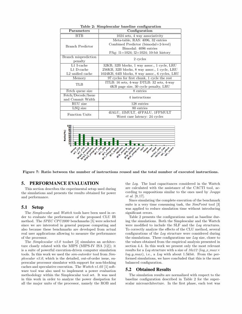
Table 2: Simplescalar baseline configurationParameters Configuration
BTB 1024 sets, 4 way associativity
Branch Predictor
Meta-table, RAS: 4096, 32 entriesCombined Predictor (bimodal+2-level)
Bimodal: 4096 entriesPAg: l1=1024; l2=1024; 10-bit history
Branch misprediction2 cycles
penaltyL1 I-cache 32KB, 32B blocks, 1 way assoc., 1 cycle, LRUL1 D-cache 256KB, 32B blocks, 8 way assoc., 1 cycle, LRU
L2 unified cache 1024KB, 64B blocks, 8 way assoc., 6 cycles, LRUMemory 97 cycles for first chunk, 1 cycle the rest
TLBITLB: 16 sets, 4-way DTLB: 32 sets, 4-way
4KB page size, 30 cycle penalty, LRUFetch queue size 8 entries
Fetch/Decode/Issue4 instructions
and Commit WidthRUU size 128 entriesLSQ size 80 entries
Function Units4IALU, 1IMULT, 4FPALU, 1FPMULT
Worst case latency: 24 cycles
Figure 7: Ratio between the number of instructions reused and the total number of executed instructions.
5. PERFORMANCE EVALUATIONThis section describes the experimental setup used during
the simulations and presents the results obtained for powerand performance.
5.1 SetupThe Simplescalar and Wattch tools have been used in or-
der to evaluate the performance of the proposed CLU IRmethod. The SPEC CPU2000 benchmarks [5] were selectedsince we are interested in general purpose computing andalso because these benchmarks are developed from actualreal user applications allowing to measure the performanceof the processor.
The Simplescalar v3.0 toolset [2] simulates an architec-ture closely related with the MIPS (MIPS-IV ISA [12]); itis a suite of powerful execution-driven computer simulationtools. In this work we used the sim-outorder tool from Sim-plescalar v3.0, which is the detailed, out-of-order issue, su-perscalar processor simulator with support for non-blockingcaches and speculative execution. The Wattch v1.02 [1] soft-ware tool was also used to implement a power evaluationmethodology within the Simplescalar tool set. It was usedin this work in order to analyze the power dissipation forall the major units of the processor, namely the ROB and
the Log. The load capacitances considered in the Wattchare calculated with the assistance of the CACTI tool, ac-cording to suppositions similar to the ones used by Jouppiet al. [9, 17].
Since simulating the complete execution of the benchmarksuite is a very time consuming task, the SimPoint tool [3]was applied to reduce simulation time without introducingsignificant errors.
Table 2 presents the configurations used as baseline dur-ing the simulations. Both the Simplescalar and the Wattchwere modified to include the SLF and the Log structures.To correctly analyze the effects of the CLU method, severalconfigurations of the Log structure were considered duringthe simulations. These configurations use Log size, closer tothe values obtained from the empirical analysis presented insection 4.4. In this work we present only the most relevantresults for a Log structure with a size of 16x12 (log x max×log y max), i.e., a Log with about 1.5kbit. From the per-formed simulations, we have concluded that this is the mostbalanced configuration.
5.2 Obtained ResultsThe simulation results are normalized with respect to the
baseline configuration described in Table 2 for the super-scalar microarchitecture. In the first phase, each test was
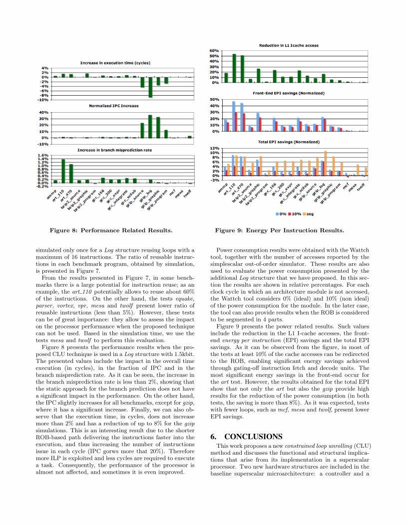
Figure 8: Performance Related Results. Figure 9: Energy Per Instruction Results.
simulated only once for a Log structure reusing loops with amaximum of 16 instructions. The ratio of reusable instruc-tions in each benchmark program, obtained by simulation,is presented in Figure 7.
From the results presented in Figure 7, in some bench-marks there is a large potential for instruction reuse; as anexample, the art 110 potentially allows to reuse about 60%of the instructions. On the other hand, the tests equake,parser, vortex, vpr, mesa and twolf present lower ratio ofreusable instructions (less than 5%). However, these testscan be of great importance: they allow to assess the impacton the processor performance when the proposed techniquecan not be used. Based in the simulation time, we use thetests mesa and twolf to perform this evaluation.
Figure 8 presents the performance results when the pro-posed CLU technique is used in a Log structure with 1.5kbit.The presented values include the impact in the overall timeexecution (in cycles), in the fraction of IPC and in thebranch misprediction rate. As it can be seen, the increase inthe branch misprediction rate is less than 2%, showing thatthe static approach for the branch prediction does not havea significant impact in the performance. On the other hand,the IPC slightly increases for all benchmarks, except for gzip,where it has a significant increase. Finally, we can also ob-serve that the execution time, in cycles, does not increasemore than 2% and has a reduction of up to 8% for the gzipsimulations. This is an interesting result due to the shorterROB-based path delivering the instructions faster into theexecution, and thus increasing the number of instructionsissue in each cycle (IPC gorws more that 20%). Thereforemore ILP is exploited and less cycles are required to executea task. Consequently, the performance of the processor isalmost not affected, and sometimes it is even improved.
Power consumption results were obtained with the Wattchtool, together with the number of accesses reported by thesimplescalar out-of-order simulator. These results are alsoused to evaluate the power consumption presented by theadditional Log structure that we have proposed. In this sec-tion the results are shown in relative percentages. For eachclock cycle in which an architecture module is not accessed,the Wattch tool considers 0% (ideal) and 10% (non ideal)of the power consumption for the module. In the later case,the tool can also provide results when the ROB is consideredto be segmented in 4 parts.
Figure 9 presents the power related results. Such valuesinclude the reduction in the L1 I-cache accesses, the front-end energy per instruction (EPI) savings and the total EPIsavings. As it can be observed from the figure, in most ofthe tests at least 10% of the cache accesses can be redirectedto the ROB, enabling significant energy savings achievedthrough gating-off instruction fetch and decode units. Themost significant energy savings in the front-end occur forthe art test. However, the results obtained for the total EPIshow that not only the art but also the gzip provide highresults for the reduction of the power consumption (in bothtests, the saving is more than 8%). As it was expected, testswith fewer loops, such as mcf, mesa and twolf, present lowerEPI savings.
6. CONCLUSIONSThis work proposes a new constrained loop unrolling (CLU)
method and discusses the functional and structural implica-tions that arise from its implementation in a superscalarprocessor. Two new hardware structures are included in thebaseline superscalar microarchitecture: a controller and a
small Log buffer to store important information when in-structions are reused.
The simulations performed using the SPEC CPU200 bench-mark suite show that the instruction reuse CLU method canreduce the power consumption and improve the efficiency ofsuperscalar processors. Simulation results reveal that thereis an average improvement in the power efficiency of the pro-cessor for the considered configuration of more than 6% anda peak gain of 10% for the gzip log program.
Better results are expected for applications with regularprocessing, such as signal processing, data compression, andmultimedia as perceived from the good results obtained withthe benchmarks art, bzip2 and gzip. Moreover, the obtainedresults show that the power consumption in the front-endof the processor is reduced by 15%, in average, when theCLU method is applied. As a final conclusion, it can bestated that the design of the Log structure is an importantstep when implementing the proposed CLU method, sinceits characteristics affect the overall power consumption andperformance of the processor.
7. ACKNOWLEDGMENTSThis work has been supported by the HiPEAC European
Network of Excellence.
8. REFERENCES[1] D. Brooks, V. Tiwari, and M. Martonosi. Wattch: a
framework for architectural-level power analysis andoptimizations. In Proceedings of the 27th AnnualInternational Symposium on Computer Architecture(ISCA’00), pages 83–94, June 2000.
[2] D. Burger and T. M. Austin. The simplescalar toolset, version 2.0. SIGARCH Comput. Archit. News,25(3):13–25, 1997.
[3] G. Hamerly, E. Perelman, J. Lau, and B. Calder.Simpoint 3.0: Faster and more flexible programanalysis. The Journal of Instruction-Level Parallelism,7, Sep 2005.
[4] J. L. Hennessy and D. A. Patterson. ComputerArchitecture: a Quantitative Approach. MorganKaufmann Publishers Inc., San Francisco, CA, USA,3rd edition, 2003.
[5] J. L. Henning. SPEC CPU2000: Measuring CPUPerformance in the New Millennium. Computer,33(7):28–35, 2000.
[6] J. S. Hu, N. Vijaykrishnan, S. Kim, M. Kandemir, andM. J. Irwin. Scheduling reusable instructions for powerreduction. In DATE ’04: Proceedings of theConference on Design, Automation and Test inEurope, page 10148. IEEE Computer Society,February 2004.
[7] S. Manne, A. Klauser, and D. Grunwald. Pipelinegating: Speculation control for energy reduction.ISCA ’98: Proceedings of the 25th AnnualInternational Symposium on Computer Architecture,00:132–141, 1998.
[8] G. E. Moore. Cramming more components ontointegrated circuits. Proceedings of the IEEE, 86:82–85,Jan 1998.
[9] S. Palacharla, N. P. Jouppi, and J. E. Smith.Complexity-effective superscalar processors. In ISCA’97: Proceedings of the 24th annual internationalsymposium on Computer architecture, pages 206–218,1997.
[10] S. J. Patel, D. H. Friendly, and Y. N. Patt. Criticalissues regarding the trace cache fetch mechanism.Technical Report CSE-TR-335-97, University ofMichigan, July 1997.
[11] F. Pratas. Low power microarchitecture withinstruction reuse. Technical Report 21, INESC-ID,September 2007.
[12] C. Price. MIPS IV Instruction Set, revision 3.2. MIPSTechnologies, Inc., Mountain View, CA, September1995.
[13] J. P. Shen and M. H. Lipasti. Modern ProcessorDesign: Fundamentals of Superscalar Processors.McGraw-Hill Companies, Inc., New York, NY, USA,1st edition, 2005.
[14] A. Sodani and G. S. Sohi. Dynamic instruction reuse.In Proceedings of the 24th Annual InternationalSymposium on Computer Architecture (ISCA’97),pages 194–205, June 1997.
[15] E. Talpes and D. Marculescu. Power reductionthrough work reuse. In ISLPED ’01: Proceedings ofthe 2001 International Symposium on Low PowerElectronics and Design, pages 340–345, 2001.
[16] E. Talpes and D. Marculescu. Execution cache-basedmicroarchitecture power-efficient superscalarprocessors. IEEE Trans. Very Large Scale Integr.Syst., 13(1):14–26, 2005.
[17] S. Wilton and N. Jouppi. Cacti: An enhanced cacheaccess and cycle time model. IEEE Journal ofSolid-State Circuits, 31:677–688, may 1996.
[18] C. Yang and A. Orailoglu. Power-efficient instructiondelivery through trace reuse. In PACT ’06:Proceedings of the 15th International Conference onParallel Architectures and Compilation Techniques,pages 192–201, Sept. 2006.