Embed Size (px)
Citation preview

Levante Sistemas de Automatización y Control S.L.
Catálogos
www.lsa-control.com
Distribuidor oficial Bosch Rexroth, Indramat, Bosch y Aventics.
LSA Control S.L. - Bosch Rexroth Sales PartnerRonda Narciso Monturiol y Estarriol, 7-9Edificio TecnoParQ Planta 1ª Derecha, Oficina 14(Parque Tecnológico de Paterna)46980 Paterna (Valencia)Telf. (+34) 960 62 43 01 [email protected] www.lsa-control.com www.boschrexroth.es

Rexroth IndraControl VCP 20
IndustrialHydraulics
Electric Drivesand Controls
Linear Motion and Assembly Technologies Pneumatics
ServiceAutomation
MobileHydraulics
Rexroth IndraDyn A SeriesAsynchronous Motors MAD/MAF
R911295781Edition 02
Project Planning Manual
LSA Control S.L. www.lsa-control.com [email protected] (+34) 960 62 43 01

About this Documentation DOK-MOTOR*-MAD/MAF****-PR01-EN-P
Rexroth IndraDyn A Series
Rexroth IndraDyn A SeriesAsynchronous Motors MAD/MAF
Project Planning Manual
DOK-MOTOR*-MAD/MAF****-PR02-EN-P
• 29578102_Book.doc• Document Number 120-1500-B321-02/EN
This documentation• explains product features and applications, technical data as well as
conditions and limits for operation.• provides guidelines for product selection, application, handling and
operation.
Description ReleaseDate
Notes
DOK-MOTOR*-MAD/MAF****-PR01-EN-P 11.2003 1st edition
DOK-MOTOR*-MAD/MAF****-PR02-EN-P 02.2005 1st reprint
Bosch Rexroth AG, 2004Copying this document, giving it to others and the use or communicationof the contents thereof without express authority, are forbidden. Offendersare liable for the payment of damages. All rights are reserved in the eventof the grant of a patent or the registration of a utility model or design(DIN 34-1).
The specified data is for product description purposes only and may notbe deemed to be guaranteed unless expressly confirmed in the contract.All rights are reserved with respect to the content of this documentationand the availability of the product.
Bosch Rexroth AGBgm.-Dr.-Nebel-Str. 2 • D-97816 Lohr a. Main
Tel +49 (0)93 52 / 40-0 • Tx 68 94 21 • Fax +49 (0)93 52 / 40-48 85http://www.boschrexroth.com/Dept. EDM1 (FS)
This document has been printed on chlorine-free bleached paper.
Title
Type of Documentation
Document Typecode
Internal File Reference
Purpose of Documentation
Record of Revisions
Copyright
Validity
Published by
Note
LSA Control S.L. www.lsa-control.com [email protected] (+34) 960 62 43 01

Rexroth IndraDyn A Table of Contents I
Table of Contents
1 Introduction to the Product 1-11.1 About this Documentation............................................................................................................. 1-2
Additional Components ........................................................................................................... 1-3Feedback ................................................................................................................................. 1-3Standards ................................................................................................................................ 1-3
2 Important directions for use 2-12.1 Appropriate use ............................................................................................................................ 2-1
Introduction .............................................................................................................................. 2-1Areas of use and application ................................................................................................... 2-2
2.2 Inappropriate use.......................................................................................................................... 2-2
3 Safety Instructions for Electric Drives and Controls 3-13.1 Introduction ................................................................................................................................... 3-13.2 Explanations ................................................................................................................................. 3-13.3 Hazards by Improper Use............................................................................................................. 3-23.4 General Information ...................................................................................................................... 3-33.5 Protection Against Contact with Electrical Parts........................................................................... 3-53.6 Protection Against Electric Shock by Protective Low Voltage (PELV) ......................................... 3-63.7 Protection Against Dangerous Movements .................................................................................. 3-73.8 Protection Against Magnetic and Electromagnetic Fields During Operation and
Mounting ....................................................................................................................................... 3-93.9 Protection Against Contact with Hot Parts.................................................................................. 3-103.10 Protection During Handling and Mounting.................................................................................. 3-103.11 Battery Safety ............................................................................................................................. 3-113.12 Protection Against Pressurized Systems.................................................................................... 3-11
4 Technical Data 4-14.1 Operating Modes .......................................................................................................................... 4-14.2 Operating Behavior....................................................................................................................... 4-24.3 Technical Data Sheet for MAD100B............................................................................................. 4-4
Characteristic Curves of MAD100B......................................................................................... 4-54.4 Technical Data Sheet for MAD100C ............................................................................................ 4-8
Characteristic Curves of MAD100C......................................................................................... 4-94.5 Technical Data Sheet for MAD100D .......................................................................................... 4-12
Characteristic Curves of MAD100D....................................................................................... 4-134.6 Technical Data Sheet for MAD130B........................................................................................... 4-16
Characteristic Curves of MAD130B....................................................................................... 4-174.7 Technical Data Sheet for MAD130C .......................................................................................... 4-20
LSA Control S.L. www.lsa-control.com [email protected] (+34) 960 62 43 01

II Table of Contents Rexroth IndraDyn A
Characteristic Curves of MAD130C....................................................................................... 4-214.8 Technical Data Sheet for MAD130D .......................................................................................... 4-24
Characteristic Curves of MAD130D....................................................................................... 4-254.9 Technical Data Sheet for MAD160B........................................................................................... 4-28
Characteristic Curve of MAD160B......................................................................................... 4-294.10 Technical Data Sheet for MAD160C .......................................................................................... 4-31
Characteristic Curves of MAD160C....................................................................................... 4-324.11 Technical Data Sheet for MAD180C .......................................................................................... 4-34
Characteristic Curves of MAD180C....................................................................................... 4-354.12 Technical Data Sheet for MAD180D .......................................................................................... 4-37
Characteristic Curves of MAD180D....................................................................................... 4-384.13 Technical Data Sheet for MAF100B ........................................................................................... 4-40
Characteristic Curves of MAF100B ....................................................................................... 4-414.14 Technical Data Sheet for MAF100C........................................................................................... 4-44
Characteristic Curves of MAF100B ....................................................................................... 4-454.15 Technical Data Sheet for MAF100D........................................................................................... 4-48
Characteristic Curves of MAF100D....................................................................................... 4-494.16 Technical Data sheet for MAF130B............................................................................................ 4-52
Characteristic Curves of MAF130B ....................................................................................... 4-534.17 Technical Data Sheet for MAF130C........................................................................................... 4-56
Characteristic Curves of MAF130C....................................................................................... 4-574.18 Technical Data Sheet for MAF130D........................................................................................... 4-60
Characteristic Curves of MAF130D....................................................................................... 4-614.19 Technical Data Sheet for MAF160B ........................................................................................... 4-64
Characteristic Curves of MAF160B ....................................................................................... 4-654.20 Technical Data Sheet for MAF160C........................................................................................... 4-67
Characteristic Curves of MAF160C....................................................................................... 4-684.21 Technical Data Sheet for MAF180C........................................................................................... 4-70
Characteristic Curves of MAF180C....................................................................................... 4-714.22 Technical Data Sheet for MAF180D........................................................................................... 4-73
Characteristic Curves of MAF180D....................................................................................... 4-74
5 Dimension Sheets 5-15.1 Dimension Sheet for MAD100, without Brake .............................................................................. 5-15.2 Dimension Sheet for MAD100, with Brakes 1 and 5 .................................................................... 5-25.3 Dimension Sheet for MAD130, without Brake .............................................................................. 5-35.4 Dimension Sheet for MAD130, with Brakes 1 and 5 .................................................................... 5-45.5 Dimension Sheet for MAD160, without Brake .............................................................................. 5-55.6 Dimension Sheet for MAD160, with Brakes 1 and 5 .................................................................... 5-65.7 Dimension Sheet for MAD160, with Brake 3 ................................................................................ 5-75.8 Dimension Sheet for MAD180, without Brake .............................................................................. 5-85.9 Dimension Sheet for MAD180, with Brakes 2 and 5 .................................................................... 5-95.10 Dimension Sheet for MAF100, without Brake............................................................................. 5-105.11 Dimension Sheet for MAF100, with Brakes 1 and 5................................................................... 5-115.12 Dimension Sheet for MAF130, without Brake............................................................................. 5-125.13 Dimension Sheet for MAF130, with Brakes 1 and 5................................................................... 5-13
LSA Control S.L. www.lsa-control.com [email protected] (+34) 960 62 43 01

Rexroth IndraDyn A Table of Contents III
5.14 Dimension Sheet for MAF160, without Brake............................................................................. 5-145.15 Dimension Sheet for MAF160, with Brakes 1 and 5................................................................... 5-155.16 Dimension Sheet for MAF160, with Brake 3............................................................................... 5-165.17 Dimension Sheet for MAF180, without Brake............................................................................. 5-175.18 Dimension Sheet for MAF180, with Brakes 2 and 5................................................................... 5-18
6 Type Codes 6-16.1 Introduction ................................................................................................................................... 6-1
Definition.................................................................................................................................. 6-16.2 Type Code for MAD100 ................................................................................................................ 6-46.3 Type Code for MAD130 ................................................................................................................ 6-66.4 Type Code for MAD160 ................................................................................................................ 6-86.5 Type Code for MAD180 .............................................................................................................. 6-106.6 Type Code for MAF100 .............................................................................................................. 6-126.7 Type Code for MAF130 .............................................................................................................. 6-146.8 Type Code for MAF160 .............................................................................................................. 6-166.9 Type Code for MAF180 .............................................................................................................. 6-18
7 Accessories 7-17.1 Labyrinth Seal............................................................................................................................... 7-17.2 Air-pressure Connector Kit ........................................................................................................... 7-27.3 Gearboxes .................................................................................................................................... 7-3
8 Connection Techniques 8-18.1 Notes............................................................................................................................................. 8-18.2 Power Connection ........................................................................................................................ 8-2
Overview.................................................................................................................................. 8-28.3 Power Connection via Flange Socket........................................................................................... 8-3
Flange Socket.......................................................................................................................... 8-38.4 Power Connection via Terminal Box ............................................................................................ 8-4
Terminal box ............................................................................................................................ 8-48.5 Connection Designations on the Drive Device ............................................................................. 8-58.6 Double Cabling ............................................................................................................................. 8-68.7 Encoder Connection ..................................................................................................................... 8-78.8 Temperature Sensors ................................................................................................................... 8-98.9 Holding Brake ............................................................................................................................. 8-108.10 Motor Cooling ............................................................................................................................. 8-10
Blower Connection ................................................................................................................ 8-10Connection of Liquid Cooling................................................................................................. 8-11Operating Pressure ............................................................................................................... 8-11Snap-On Couplings ............................................................................................................... 8-12
9 Application Notes 9-19.1 Operating Conditions .................................................................................................................... 9-1
Setup Elevation and Ambient Temperature ............................................................................ 9-19.2 Humidity........................................................................................................................................ 9-2
LSA Control S.L. www.lsa-control.com [email protected] (+34) 960 62 43 01

IV Table of Contents Rexroth IndraDyn A
9.3 Vibration and Shock...................................................................................................................... 9-2Vibration................................................................................................................................... 9-2Shock....................................................................................................................................... 9-3
9.4 Compatibility with Foreign Material............................................................................................... 9-39.5 Degree of Protection..................................................................................................................... 9-49.6 Design and Installation Position ................................................................................................... 9-5
Vertical Assembly .................................................................................................................... 9-69.7 Housing Paint ............................................................................................................................... 9-79.8 Motor Cooling ............................................................................................................................... 9-8
Blower...................................................................................................................................... 9-8Coolants................................................................................................................................... 9-9Materials used in the Cooling System ................................................................................... 9-10Inlet Temperature of Coolant................................................................................................. 9-11
9.9 Motor Temperature Overview..................................................................................................... 9-129.10 Motor Holding Brake (Option) ..................................................................................................... 9-13
Selecting Holding Brakes ...................................................................................................... 9-14Dimensioning of Holding Brakes (Application) ...................................................................... 9-15
9.11 Motor Encoder ............................................................................................................................ 9-17Options .................................................................................................................................. 9-17Compatibility .......................................................................................................................... 9-17Accuracy/Repeatability .......................................................................................................... 9-18Connection of the Encoder .................................................................................................... 9-19
9.12 Output Shaft................................................................................................................................ 9-19Plain Shaft ............................................................................................................................. 9-19Output Shaft with Key............................................................................................................ 9-19Output Shaft with Seal........................................................................................................... 9-20
9.13 Bearing and Shaft Loads ............................................................................................................ 9-22Radial Load, Axial Load......................................................................................................... 9-22
9.14 Attachment of Drive Elements .................................................................................................... 9-26Couplings............................................................................................................................... 9-27Helical Driving Pinion............................................................................................................. 9-28Bevel Gear Pinion.................................................................................................................. 9-28
9.15 Bearing Lifetime.......................................................................................................................... 9-299.16 Grease Service Life .................................................................................................................... 9-309.17 Types of Bearing......................................................................................................................... 9-33
Tips for Selection................................................................................................................... 9-359.18 Vibration Severity Class.............................................................................................................. 9-369.19 Acceptances and Authorizations ................................................................................................ 9-37
CE Symbol............................................................................................................................. 9-37UR, cUR Listing ..................................................................................................................... 9-37
10 Handling and Transportation 10-110.1 Delivery status ............................................................................................................................ 10-1
Factory Test........................................................................................................................... 10-1Inspection Tests by the Customer......................................................................................... 10-1
10.2 Identification................................................................................................................................ 10-2
LSA Control S.L. www.lsa-control.com [email protected] (+34) 960 62 43 01

Rexroth IndraDyn A Table of Contents V
10.3 Designation................................................................................................................................. 10-210.4 Transportation and Storage........................................................................................................ 10-3
11 Installation 11-111.1 Safety.......................................................................................................................................... 11-111.2 Mechanical Attachment .............................................................................................................. 11-1
Mounting Holes...................................................................................................................... 11-1Preparation ............................................................................................................................ 11-2Assembly ............................................................................................................................... 11-2
Electrical Connection ............................................................................................................................ 11-2
12 Operating IndraDyn A Motors 12-112.1 Commissioning ........................................................................................................................... 12-1
Preparation ............................................................................................................................ 12-1Execution ............................................................................................................................... 12-1
12.2 Deactivation ................................................................................................................................ 12-212.3 Dismantling ................................................................................................................................. 12-212.4 Maintenance ............................................................................................................................... 12-3
Measures ............................................................................................................................... 12-3MAD � Motor blower.............................................................................................................. 12-4MAF � Coolant Supply........................................................................................................... 12-5Maintaining Holding Brakes................................................................................................... 12-5
12.5 Troubleshooting .......................................................................................................................... 12-6Excess Temperature of Motor Housing................................................................................. 12-6High motor temperature values, but housing temperature is normal .................................... 12-7Motor or Rotary Table Generates Vibrations......................................................................... 12-7Specified Position is not Attained .......................................................................................... 12-8
13 Service & Support 13-113.1 Helpdesk..................................................................................................................................... 13-113.2 Service-Hotline ........................................................................................................................... 13-113.3 Internet........................................................................................................................................ 13-113.4 Vor der Kontaktaufnahme... - Before contacting us... ................................................................ 13-113.5 Kundenbetreuungsstellen - Sales & Service Facilities ............................................................... 13-2
14 Index 14-1
LSA Control S.L. www.lsa-control.com [email protected] (+34) 960 62 43 01

VI Table of Contents Rexroth IndraDyn A
LSA Control S.L. www.lsa-control.com [email protected] (+34) 960 62 43 01
Rexroth IndraDyn A Introduction to the Product 1-1
1 Introduction to the ProductThe IndraDyn A series consists of housed, asynchronous motors fromBosch Rexroth. The two versions of IndraDyn A differ by their method ofcooling.
• The MAD version is air-cooled by a firmly-attached fan unit, whichforces the ambient air across the surface of the motor.
MAD.jpg
Fig. 1-1: Illustration example MAD130
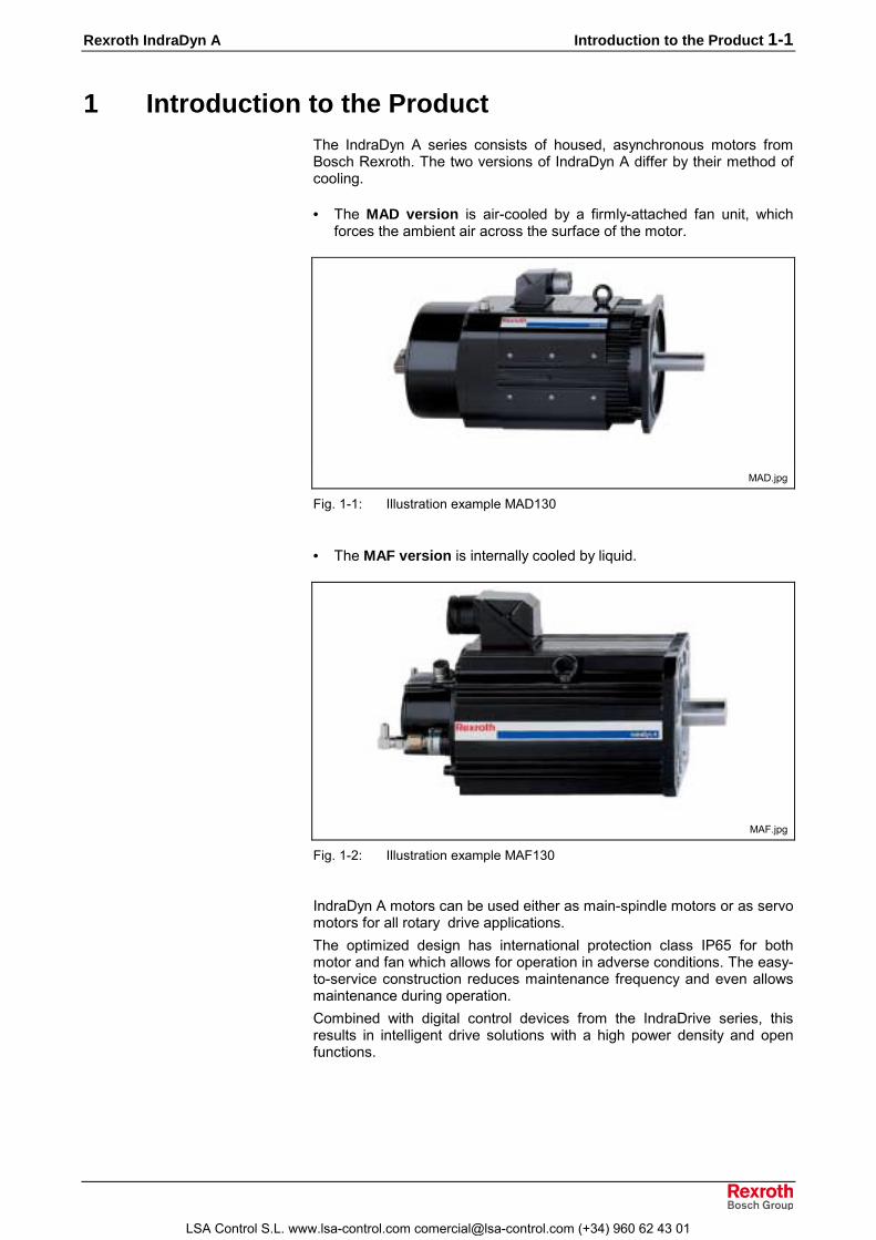
• The MAF version is internally cooled by liquid.
MAF.jpg
Fig. 1-2: Illustration example MAF130
IndraDyn A motors can be used either as main-spindle motors or as servomotors for all rotary drive applications.The optimized design has international protection class IP65 for bothmotor and fan which allows for operation in adverse conditions. The easy-to-service construction reduces maintenance frequency and even allowsmaintenance during operation.Combined with digital control devices from the IndraDrive series, thisresults in intelligent drive solutions with a high power density and openfunctions.
LSA Control S.L. www.lsa-control.com [email protected] (+34) 960 62 43 01

1-2 Introduction to the Product Rexroth IndraDyn A
1.1 About this Documentation
Document structureThis documentation includes safety regulations, technical data andoperating instructions. The following setup provides an overview of thecontents of this documentation.
Sect. Title Content
1 Introduction Introduction to the product andnotes
2 Important Instructions on Use3 Safety
Important safety notes
4 Technical data5 Dimension Sheets6 Type Codes
Productdescription
7 Accessories8 Connection Techniques
for planners andprojectors
9 Application notes10 Handling & Transport11 Installation12 Operation13 Service and Support
Practicefor operating and
maintenancepersonnel
14 Index Additional information
Fig. 1-3: Chapter structure
Supplementary DocumentationTo project planning the drive-systems of the IndraDyn A motor series, youmay need additional documentation depending on the devices used inyour case. Rexroth provides all product documentation on CD in a PDF-format. To project planning a system, you will not need all thedocumentations included on the CD.
Note: All documentations on the CD are also available in a printedversion. You can order the required product documentationsvia your Rexroth sales office.
Material no.: Title / descriptionR911281882 -Product documentation Electric Drives and Controls Version xx 1)
DOK-GENRL-CONTR*DRIVE-GNxx-DE-D650 (German)
R911281883 -Product documentation Electric Drives and Controls Version xx 1)
DOK-GENRL-CONTR*DRIVE-GNxx-EN-D650 (English)
1) The index (e.g. ..02-...) identifies the version of the CD.
Fig. 1-4: Supplementary Documentation
LSA Control S.L. www.lsa-control.com [email protected] (+34) 960 62 43 01

Rexroth IndraDyn A Introduction to the Product 1-3
Additional ComponentsDocumentation for external systems, which are connected to BoschRexroth components, are not included in the scope of delivery and mustbe ordered directly from the particular manufacturers.For information on the manufacturers see Chapter 9 �Application Notes�.
FeedbackYour experiences are an essential part of the process of improving bothproduct and documentation.Please do not hesitate to inform us of any mistakes you detect in thisdocumentation or of any modifications you might desire. We wouldappreciate your feedback.Please send your remarks to:
Rexroth Indramat GmbHDep. BRC/EDM1Bürgermeister-Dr.-Nebel-Strasse 2D-97816 Lohr, GermanyFax +49 (0) 93 52 / 40-43 80
StandardsThis documentation refers to German, European and internationaltechnical standards. Documents and sheets on standards underlie theprotection by copyright and may not be passed on to third parties byREXROTH INDRAMAT. If necessary, please contact your localauthorized sales office or, in Germany, contact:BEUTH Verlag GmbHBurggrafenstrasse 610787 BerlinPhone +49-(0)30-26 01-22 60, Fax +49-(0)30-26 01-12 60Internet: http://www.din.de/beuth [email protected]
LSA Control S.L. www.lsa-control.com [email protected] (+34) 960 62 43 01

1-4 Introduction to the Product Rexroth IndraDyn A
LSA Control S.L. www.lsa-control.com [email protected] (+34) 960 62 43 01

Rexroth IndraDyn A Important directions for use 2-1
2 Important directions for use
2.1 Appropriate use
IntroductionBosch Rexroth products represent state-of-the-art developments andmanufacturing. They are 100% tested prior to delivery to ensure operatingsafety and reliability.The products may only be used in the manner that is defined asappropriate. If they are used in an inappropriate manner, then situationscan develop that may lead to property damage or injury to personnel.
Note: Bosch Rexroth, as manufacturer, is not liable for any damagesresulting from inappropriate use. In such cases, the guaranteeand the right to payment of damages resulting frominappropriate use are forfeited. The user alone carries allresponsibility of the risks.
Before using Bosch Rexroth products, make sure that all the pre-requisites for appropriate use of the products are satisfied:• Personnel that in any way, shape or form uses our products must first
read and understand the relevant safety instructions and be familiarwith appropriate use.
• If the product takes the form of hardware, then they must remain intheir original state. In other words, no structural changes arepermitted. It is not permitted to decompile software products or altersource codes.
• Do not mount damaged or faulty products or use them in operation.• Make sure that the products have been installed in the manner
described in the relevant documentation.
LSA Control S.L. www.lsa-control.com [email protected] (+34) 960 62 43 01

2-2 Important directions for use Rexroth IndraDyn A
Areas of use and applicationAsynchronous motors of the IndraDyn A line made by Bosch Rexroth aredesigned to be used as rotary main-spindle and servo-drive motors.Typical applications are in:• machine tools,• printing and paper processing machines,• packaging and foodstuff machines and• metal-forming machine tools.
Several types of motors with differing drive power and different interfacesare available for application-specific uses.Control and monitoring of the motors may require additional sensors andactors.
Note: The motors may only be used with the accessories and partsspecified in this document. If a component has not beenspecifically named, then it may not be either mounted orconnected. The same applies to cables and lines.Operation is only permitted in the specified configurations andcombinations of components using the software and firmwareas specified in the relevant function descriptions.
Every drive controller has to be programmed before starting it up, makingit possible for the motor to execute the specific functions of an application.The motors may only be operated under the assembly, installation andambient conditions as described here (temperature, IP-Class, humidity,EMC requirements, etc.) and in the position specified.
2.2 Inappropriate useInappropriate use is defined as using the motors outside of the above-referenced areas of application or under operating conditions other thandescribed in the document and the technical data specified.IndraDyn A motors may not be used if• they are subject to operating conditions that do not meet the above
specified ambient conditions. This includes, for example, operationunder water, in the case of extreme temperature fluctuations orextremely high maximum temperatures or if
• Bosch Rexroth has not specifically released them for that intendedpurpose. Please note the specifications outlined in the general SafetyGuidelines!
LSA Control S.L. www.lsa-control.com [email protected] (+34) 960 62 43 01

Rexroth IndraDyn A Safety Instructions for Electric Drives and Controls 3-1
3 Safety Instructions for Electric Drives and Controls
3.1 IntroductionRead these instructions before the initial startup of the equipment in orderto eliminate the risk of bodily harm or material damage. Follow thesesafety instructions at all times.Do not attempt to install or start up this equipment without first reading alldocumentation provided with the product. Read and understand thesesafety instructions and all user documentation of the equipment prior toworking with the equipment at any time. If you do not have the userdocumentation for your equipment, contact your local Bosch Rexrothrepresentative to send this documentation immediately to the person orpersons responsible for the safe operation of this equipment.If the equipment is resold, rented or transferred or passed on to others,then these safety instructions must be delivered with the equipment.
WARNING
Improper use of this equipment, failure to followthe safety instructions in this document ortampering with the product, including disablingof safety devices, may result in materialdamage, bodily harm, electric shock or evendeath!
3.2 ExplanationsThe safety instructions describe the following degrees of hazardseriousness in compliance with ANSI Z535. The degree of hazardseriousness informs about the consequences resulting from non-compliance with the safety instructions.
Warning symbol with signalword
Degree of hazard seriousness accordingto ANSI
DANGER
Death or severe bodily harm will occur.
WARNING
Death or severe bodily harm may occur.
CAUTION
Bodily harm or material damage may occur.
Fig. 3-1: Hazard classification (according to ANSI Z535)
LSA Control S.L. www.lsa-control.com [email protected] (+34) 960 62 43 01

3-2 Safety Instructions for Electric Drives and Controls Rexroth IndraDyn A
3.3 Hazards by Improper Use
DANGER
High voltage and high discharge current!Danger to life or severe bodily harm by electricshock!
DANGER
Dangerous movements! Danger to life, severebodily harm or material damage byunintentional motor movements!
WARNING
High electrical voltage due to wrongconnections! Danger to life or bodily harm byelectric shock!
WARNING
Health hazard for persons with heartpacemakers, metal implants and hearing aids inproximity to electrical equipment!
CAUTION
Surface of machine housing could be extremelyhot! Danger of injury! Danger of burns!
CAUTION
Risk of injury due to improper handling! Bodilyharm caused by crushing, shearing, cutting andmechanical shock or incorrect handling ofpressurized systems!
CAUTION
Risk of injury due to incorrect handling ofbatteries!
LSA Control S.L. www.lsa-control.com [email protected] (+34) 960 62 43 01

Rexroth IndraDyn A Safety Instructions for Electric Drives and Controls 3-3
3.4 General Information• Bosch Rexroth AG is not liable for damages resulting from failure to
observe the warnings provided in this documentation.• Read the operating, maintenance and safety instructions in your
language before starting up the machine. If you find that you cannotcompletely understand the documentation for your product, please askyour supplier to clarify.
• Proper and correct transport, storage, assembly and installation aswell as care in operation and maintenance are prerequisites foroptimal and safe operation of this equipment.
• Only persons who are trained and qualified for the use and operationof the equipment may work on this equipment or within its proximity.• The persons are qualified if they have sufficient knowledge of the
assembly, installation and operation of the equipment as well as anunderstanding of all warnings and precautionary measures noted inthese instructions.
• Furthermore, they must be trained, instructed and qualified toswitch electrical circuits and equipment on and off in accordancewith technical safety regulations, to ground them and to mark themaccording to the requirements of safe work practices. They musthave adequate safety equipment and be trained in first aid.
• Only use spare parts and accessories approved by the manufacturer.• Follow all safety regulations and requirements for the specific
application as practiced in the country of use.• The equipment is designed for installation in industrial machinery.• The ambient conditions given in the product documentation must be
observed.• Use only safety features and applications that are clearly and explicitly
approved in the Project Planning Manual. If this is not the case, theyare excluded.The following areas of use and application, for example, include safetyfeatures and applications: construction cranes, elevators used forpeople or freight, devices and vehicles to transport people, medicalapplications, refinery plants, transport of hazardous goods, nuclearapplications, applications in which electrical devices with vital functionscan be electromagnetically disturbed, mining, food processing, controlof protection equipment (also in a machine).
• The information given in the documentation of the product with regardto the use of the delivered components contains only examples ofapplications and suggestions.The machine and installation manufacturer must• make sure that the delivered components are suited for his
individual application and check the information given in thisdocumentation with regard to the use of the components,
• make sure that his application complies with the applicable safetyregulations and standards and carry out the required measures,modifications and complements.
• Startup of the delivered components is only permitted once it is surethat the machine or installation in which they are installed complieswith the national regulations, safety specifications and standards of theapplication.
LSA Control S.L. www.lsa-control.com [email protected] (+34) 960 62 43 01
3-4 Safety Instructions for Electric Drives and Controls Rexroth IndraDyn A
• Operation is only permitted if the national EMC regulations for theapplication are met.The instructions for installation in accordance with EMC requirementscan be found in the documentation "EMC in Drive and ControlSystems".The machine or installation manufacturer is responsible forcompliance with the limiting values as prescribed in the nationalregulations.
• Technical data, connections and operational conditions are specified inthe product documentation and must be followed at all times.
LSA Control S.L. www.lsa-control.com [email protected] (+34) 960 62 43 01

Rexroth IndraDyn A Safety Instructions for Electric Drives and Controls 3-5
3.5 Protection Against Contact with Electrical Parts
Note: This section refers to equipment and drive components withvoltages above 50 Volts.
Touching live parts with voltages of 50 Volts and more with bare hands orconductive tools or touching ungrounded housings can be dangerous andcause electric shock. In order to operate electrical equipment, certainparts must unavoidably have dangerous voltages applied to them.
DANGER
High electrical voltage! Danger to life, severebodily harm by electric shock!⇒ Only those trained and qualified to work with or on
electrical equipment are permitted to operate, maintainor repair this equipment.
⇒ Follow general construction and safety regulations whenworking on high voltage installations.
⇒ Before switching on power the ground wire must bepermanently connected to all electrical units accordingto the connection diagram.
⇒ Do not operate electrical equipment at any time, evenfor brief measurements or tests, if the ground wire is notpermanently connected to the points of the componentsprovided for this purpose.
⇒ Before working with electrical parts with voltage higherthan 50 V, the equipment must be disconnected fromthe mains voltage or power supply. Make sure theequipment cannot be switched on again unintended.
⇒ The following should be observed with electrical driveand filter components:
⇒ Wait thirty (30) minutes after switching off power toallow capacitors to discharge before beginning to work.Measure the voltage on the capacitors before beginningto work to make sure that the equipment is safe totouch.
⇒ Never touch the electrical connection points of acomponent while power is turned on.
⇒ Install the covers and guards provided with theequipment properly before switching the equipment on.Prevent contact with live parts at any time.
⇒ A residual-current-operated protective device (RCD)must not be used on electric drives! Indirect contactmust be prevented by other means, for example, by anovercurrent protective device.
⇒ Electrical components with exposed live parts anduncovered high voltage terminals must be installed in aprotective housing, for example, in a control cabinet.
LSA Control S.L. www.lsa-control.com [email protected] (+34) 960 62 43 01

3-6 Safety Instructions for Electric Drives and Controls Rexroth IndraDyn A
To be observed with electrical drive and filter components:
DANGER
High electrical voltage on the housing!High leakage current! Danger to life, danger ofinjury by electric shock!⇒ Connect the electrical equipment, the housings of all
electrical units and motors permanently with the safetyconductor at the ground points before power isswitched on. Look at the connection diagram. This iseven necessary for brief tests.
⇒ Connect the safety conductor of the electricalequipment always permanently and firmly to thesupply mains. Leakage current exceeds 3.5 mA innormal operation.
⇒ Use a copper conductor with at least 10 mm² crosssection over its entire course for this safety conductorconnection!
⇒ Prior to startups, even for brief tests, always connectthe protective conductor or connect with ground wire.Otherwise, high voltages can occur on the housingthat lead to electric shock.
3.6 Protection Against Electric Shock by Protective LowVoltage (PELV)
All connections and terminals with voltages between 0 and 50 Volts onRexroth products are protective low voltages designed in accordance withinternational standards on electrical safety.
WARNING
High electrical voltage due to wrongconnections! Danger to life, bodily harm byelectric shock!⇒ Only connect equipment, electrical components and
cables of the protective low voltage type (PELV =Protective Extra Low Voltage) to all terminals andclamps with voltages of 0 to 50 Volts.
⇒ Only electrical circuits may be connected which aresafely isolated against high voltage circuits. Safeisolation is achieved, for example, with an isolatingtransformer, an opto-electronic coupler or whenbattery-operated.
LSA Control S.L. www.lsa-control.com [email protected] (+34) 960 62 43 01

Rexroth IndraDyn A Safety Instructions for Electric Drives and Controls 3-7
3.7 Protection Against Dangerous MovementsDangerous movements can be caused by faulty control of the connectedmotors. Some common examples are:• improper or wrong wiring of cable connections• incorrect operation of the equipment components• wrong input of parameters before operation• malfunction of sensors, encoders and monitoring devices• defective components• software or firmware errorsDangerous movements can occur immediately after equipment isswitched on or even after an unspecified time of trouble-free operation.The monitoring in the drive components will normally be sufficient to avoidfaulty operation in the connected drives. Regarding personal safety,especially the danger of bodily injury and material damage, this alonecannot be relied upon to ensure complete safety. Until the integratedmonitoring functions become effective, it must be assumed in any casethat faulty drive movements will occur. The extent of faulty drivemovements depends upon the type of control and the state of operation.
LSA Control S.L. www.lsa-control.com [email protected] (+34) 960 62 43 01

3-8 Safety Instructions for Electric Drives and Controls Rexroth IndraDyn A
DANGER
Dangerous movements! Danger to life, risk ofinjury, severe bodily harm or material damage!⇒ Ensure personal safety by means of qualified and
tested higher-level monitoring devices or measuresintegrated in the installation. Unintended machinemotion is possible if monitoring devices are disabled,bypassed or not activated.
⇒ Pay attention to unintended machine motion or othermalfunction in any mode of operation.
⇒ Keep free and clear of the machine�s range of motionand moving parts. Possible measures to preventpeople from accidentally entering the machine�s rangeof motion:
- use safety fences- use safety guards- use protective coverings- install light curtains or light barriers
⇒ Fences and coverings must be strong enough toresist maximum possible momentum, especially ifthere is a possibility of loose parts flying off.
⇒ Mount the emergency stop switch in the immediatereach of the operator. Verify that the emergency stopworks before startup. Don�t operate the machine if theemergency stop is not working.
⇒ Isolate the drive power connection by means of anemergency stop circuit or use a starting lockout toprevent unintentional start.
⇒ Make sure that the drives are brought to a safestandstill before accessing or entering the dangerzone. Safe standstill can be achieved by switching offthe power supply contactor or by safe mechanicallocking of moving parts.
⇒ Secure vertical axes against falling or dropping afterswitching off the motor power by, for example:
- mechanically securing the vertical axes- adding an external braking/ arrester/ clamping
mechanism- ensuring sufficient equilibration of the vertical axesThe standard equipment motor brake or an externalbrake controlled directly by the drive controller arenot sufficient to guarantee personal safety!
LSA Control S.L. www.lsa-control.com [email protected] (+34) 960 62 43 01

Rexroth IndraDyn A Safety Instructions for Electric Drives and Controls 3-9
⇒ Disconnect electrical power to the equipment using amaster switch and secure the switch againstreconnection for:
- maintenance and repair work- cleaning of equipment- long periods of discontinued equipment use
⇒ Prevent the operation of high-frequency, remotecontrol and radio equipment near electronics circuitsand supply leads. If the use of such equipment cannotbe avoided, verify the system and the installation forpossible malfunctions in all possible positions ofnormal use before initial startup. If necessary, performa special electromagnetic compatibility (EMC) test onthe installation.
3.8 Protection Against Magnetic and Electromagnetic FieldsDuring Operation and Mounting
Magnetic and electromagnetic fields generated near current-carryingconductors and permanent magnets in motors represent a serious healthhazard to persons with heart pacemakers, metal implants and hearingaids.
WARNING
Health hazard for persons with heartpacemakers, metal implants and hearing aids inproximity to electrical equipment!⇒ Persons with heart pacemakers, hearing aids and
metal implants are not permitted to enter the followingareas:
- Areas in which electrical equipment and parts aremounted, being operated or started up.
- Areas in which parts of motors with permanentmagnets are being stored, operated, repaired ormounted.
⇒ If it is necessary for a person with a heart pacemakerto enter such an area, then a doctor must beconsulted prior to doing so. Heart pacemakers thatare already implanted or will be implanted in thefuture, have a considerable variation in their electricalnoise immunity. Therefore there are no rules withgeneral validity.
⇒ Persons with hearing aids, metal implants or metalpieces must consult a doctor before they enter theareas described above. Otherwise, health hazards willoccur.
LSA Control S.L. www.lsa-control.com [email protected] (+34) 960 62 43 01

3-10 Safety Instructions for Electric Drives and Controls Rexroth IndraDyn A
3.9 Protection Against Contact with Hot Parts
CAUTION
Housing surfaces could be extremely hot!Danger of injury! Danger of burns!⇒ Do not touch housing surfaces near sources of heat!
Danger of burns!⇒ After switching the equipment off, wait at least ten (10)
minutes to allow it to cool down before touching it.⇒ Do not touch hot parts of the equipment, such as
housings with integrated heat sinks and resistors.Danger of burns!
3.10 Protection During Handling and MountingUnder certain conditions, incorrect handling and mounting of parts andcomponents may cause injuries.
CAUTION
Risk of injury by incorrect handling! Bodilyharm caused by crushing, shearing, cutting andmechanical shock!⇒ Observe general installation and safety instructions
with regard to handling and mounting.⇒ Use appropriate mounting and transport equipment.⇒ Take precautions to avoid pinching and crushing.⇒ Use only appropriate tools. If specified by the product
documentation, special tools must be used.⇒ Use lifting devices and tools correctly and safely.⇒ For safe protection wear appropriate protective
clothing, e.g. safety glasses, safety shoes and safetygloves.
⇒ Never stand under suspended loads.⇒ Clean up liquids from the floor immediately to prevent
slipping.
LSA Control S.L. www.lsa-control.com [email protected] (+34) 960 62 43 01

Rexroth IndraDyn A Safety Instructions for Electric Drives and Controls 3-11
3.11 Battery SafetyBatteries contain reactive chemicals in a solid housing. Inappropriatehandling may result in injuries or material damage.
CAUTION
Risk of injury by incorrect handling!⇒ Do not attempt to reactivate discharged batteries by
heating or other methods (danger of explosion andcauterization).
⇒ Never charge non-chargeable batteries (danger ofleakage and explosion).
⇒ Never throw batteries into a fire.⇒ Do not dismantle batteries.⇒ Do not damage electrical components installed in the
equipment.
Note: Be aware of environmental protection and disposal! Thebatteries contained in the product should be considered ashazardous material for land, air and sea transport in the senseof the legal requirements (danger of explosion). Disposebatteries separately from other waste. Observe the legalrequirements in the country of installation.
3.12 Protection Against Pressurized SystemsCertain motors and drive controllers, corresponding to the information inthe respective Project Planning Manual, must be provided withpressurized media, such as compressed air, hydraulic oil, cooling fluidand cooling lubricant supplied by external systems. Incorrect handling ofthe supply and connections of pressurized systems can lead to injuries oraccidents. In these cases, improper handling of external supply systems,supply lines or connections can cause injuries or material damage.
CAUTION
Danger of injury by incorrect handling ofpressurized systems !⇒ Do not attempt to disassemble, to open or to cut a
pressurized system (danger of explosion).⇒ Observe the operation instructions of the respective
manufacturer.⇒ Before disassembling pressurized systems, release
pressure and drain off the fluid or gas.⇒ Use suitable protective clothing (for example safety
glasses, safety shoes and safety gloves)⇒ Remove any fluid that has leaked out onto the floor
immediately.
Note: Environmental protection and disposal! The media used in theoperation of the pressurized system equipment may not beenvironmentally compatible. Media that are damaging theenvironment must be disposed separately from normal waste.Observe the legal requirements in the country of installation.
LSA Control S.L. www.lsa-control.com [email protected] (+34) 960 62 43 01

3-12 Safety Instructions for Electric Drives and Controls Rexroth IndraDyn A
Notes
LSA Control S.L. www.lsa-control.com [email protected] (+34) 960 62 43 01

Rexroth IndraDyn A Technical Data 4-1
4 Technical Data
4.1 Operating ModesBosch Rexroth motors are documented according to the test criteria andmeasuring methods of EN 60034-1. Stated technical data refer to theoperating mode S1 (continuous operation) and S6 (periodic operation),each cooled with either surface cooling via directly-connected blower unitsor with liquid cooling.
�
��� ���
��
�
�
����
��
�
�
����
��
�
���������� ������������� ��� ����
����
����
�������
P: PowerPV: Electric lossesΘ: TemperatureΘmax: Highest temperature (stator)t: TimeTC: Duty cycle time∆tP: Operating time with constant power∆tV: Idle time
Fig. 4-1: Operating modes according to EN 60034-1 :1998
ON TimeThe operating mode S6 is supplemented by specification of the ON time(ED) in %. The ON time is calculated as follows:
%100TtEDC
p ⋅= ∆
ED: Cyclic duration factor in %TC: Duty cycle time∆tP: Operating time with constant capacity
Fig. 4-2: Cyclic duration factor
LSA Control S.L. www.lsa-control.com [email protected] (+34) 960 62 43 01

4-2 Technical Data Rexroth IndraDyn A
4.2 Operating BehaviorThe following section describes the parameters, characteristic curves andthe explanations of the motor data found in the technical data sheets ofthe IndraDyn A series.
Parameters
Available torque at the rated speed in operating mode S1 (continuousoperation). Unit: Newton meters (Nm).
Typical working speed defined by the manufacturer. Depending on theparticular application, other working speeds are possible (see speed-torque characteristic curve).
Power output of the motor at the rated speed and capacity with ratedtorque, specified in kilowatts (kW).
Phase current of the motor at the rated speed and load with rated torque,specified as root-mean-square value in ampere (A).
Ratio of increase of torque to the torque-forming current of the motor.Unit: Nm/A. Valid up to the rated current IN.
The moment of inertia of the rotor without bearings and encoder. Unit:kgm².
Mass of the motor in standard version, without holding brake, specified inkilograms (kg).
Maximum allowed speed of the motor in (rpm). Normally restricted bymechanical factors like centrifugal force or bearing stress.
The time it takes for the temperature to rise to 63% of the finaltemperature of the motor under load with rated torque in S1-operation andsurface ventilation by directly-connected blower units.
��
���
����
������
���
!�" �
#$ !�"�
MAD_Definition3.EPS
(1): Path of the motor temperature over timeTth: Thermal time constant
Fig. 4-3: Thermal time constant
Duration of the cycle in S6 operating mode until the steady-statetemperature is reached and the maximum temperature equals the finaltemperature in S1 operation (see Fig. Fig. 4-1).
Quantity of pole pairs of the motor.
Rated Torque Mnenn
Rated Speed nnenn
Rated Power Pnenn
Rated Current Inenn
Torque Constant at Rated PointKM_nenn
Rotor Moment of Inertia Jrot
Mass m
Maximum Speed nmax
Thermal Time Constant Tth
Duty Cycle Time TC
Number of Pole Pairs p
LSA Control S.L. www.lsa-control.com [email protected] (+34) 960 62 43 01

Rexroth IndraDyn A Technical Data 4-3
Characteristic Curve
�
%$
%$
&�'(�
�����
)�
���*����
AsyncCurve.EPS
P [kW]: mechanical output in kilowattsM [Nm]: torque available on the output shaft, in Newton metersn [rpm]: motor speed, in revolutions per minute.(1): derating speed (n1 in data sheet)(2): rated speed (nnenn)(3): max. torque (nmax)(4): characteristic curve without derating(5): characteristic curve with derating
Fig. 4-4: IndraDyn A sample characteristic curves
Explanation:Derating is present when there is a drop in torque and power beforereaching the rated speed nnenn. This only occurs in some types of motorwindings.The continuous stand-still current, In1, is applied to the motor until thederating speed is reached.If there is no derating, In1 = Inenn.The continuous stand-still torque, M1, is available for S1 operation upto the derating speed.If there is no derating, Mn1 = Mnenn.Derating is in effect only while operating at speeds between (1) and (2)(see Fig. 4-4). Both the power and the torque are reduced in this range.
With no derating in effect, induction motors provide a constant torque (therated torque) until the rated speed. Then, starting at the rated speed,constant power (the rated power) is available.
The speed up to which a motor can safely be operated. This is normallylimited by the mechanical construction, e.g. by the type of bearings usedor by the use of a holding brake.
(1) Derating Speed
(2) Rated Speed
(3) Maximum Speed
LSA Control S.L. www.lsa-control.com [email protected] (+34) 960 62 43 01

4-4 Technical Data Rexroth IndraDyn A
4.3 Technical Data Sheet for MAD100B
Description Symbol Unit MAD100B
Motor data 1)Winding 0050 0100 0150 0200 0250Rated torque Mnenn Nm 34 31 28 28 25Rated speed nnenn rpm 500 1000 1500 2000 2500Rated power Pnenn kW 1.8 3.2 4.4 5.9 6.5Rated current Inenn A 5.3 8.9 11.8 14.6 16.2Continuous torque at standstill Mn1 Nm - 34 31 30 28Derating speed n1 rpm - 500 1000 1500 2000Continuous current at standstill In1 A - 9.4 12.5 15.3 16.8Maximum speed Mmax Nm 75 75 68 66 62Torque constant at 20°C KM_nenn Nm/A 7.66 4.31 3.03 2.41 2.11Number of pole pairs p 3Min. cross section of power cable 2) A mm² 2.5Rotor moment of inertia 3) Jrot kgm² 0.019Mass of motor 4) m kg 39
- Standard nmax rpm 3000 6000 9000- coupling attachment nmax rpm 3000 6000 6300- reinforced nmax rpm not available
Maximumspeed withbearing...
- High-speed nmax rpm 3000 6000 9000 11000 7)Thermal time constant Tth min 30Duty cycle time (S6-44%) TC min i.p.Noise level 5) pSchall dB(A) 70 (+3)Permissible ambient temperature Tum °C 0....+40Permissible storage and transporttemperature Tlager °C -20....+80
Insulation class according to DINVDE 0530-1 F
International Protection class IP65
Holding brake (optional) Electrically-clamped Electrically-releasedTransmittable torque M4 Nm 30 24Connection voltage UBr V DC 24 ± 10 %Rated current IBr A 0.9 1.1Moment of inertia JBr kgm² 0.00056Max. permissible braking energy Wmax Ws 20000Disengagement time t2 ms 50 90Engagement time t1 ms 42 30Maximum speed of brake nBr_max rpm 10000 10000Mass of brake m kg 2 1.6
Blower Axial blowerAir current B → A, blowingConnection voltage UN V 3 x 400V ± 15 %, 50/60 Hz .... 3 x 480V ± 10 %, 50/60 HzPower consumption SN VA 83 .... 100Blower current 6) IN A 0.12Average air flowrate V m³/h 2301) Values determined according to IEC 60034-1. Current and voltage specified as root-mean-square values.2) Rated for cable assemblies with current carrying capacity according to VDE0298-4 (1992) and installation type B2
according to EN 60204-1 (1993) at 40°C ambient temperature.3) Values without holding brake.4) Values without holding brake, with blower.5) at 1m distance, with PWM = 4 kHz6) From IN + 20%, blowers should be monitored.7) Value is without a holding brake. This value may be limited by a holding brake.
Fig. 4-5: Data sheet MAD100B
LSA Control S.L. www.lsa-control.com [email protected] (+34) 960 62 43 01

Rexroth IndraDyn A Technical Data 4-5
Characteristic Curves of MAD100B
������������
�+�
��+�
)�+�
��+�
%�+�
$�+�
��+�
,�+�
-�+�
�
$��
����
�$��
)���
)$��
����
��� ��������������
�����������������
�
�+$
�
�+$
)
)+$
������ ���!��"#
�
���
�����
&��
&����
����./�01���2���$������
���3��4��5���������/(��)���6��7������6�����/(��)���� 08%��69/$�:(��"1����8�����44����������/(��)�����6�����/(��)�;��"����<����<����� 08%��69/$�:
Fig. 4-6: Characteristic curve of MAD100B-0050
������������
�+�
��+�
)�+�
��+�
%�+�
$�+�
��+�
,�+�
-�+�
�
$��
����
�$��
)���
)$��
����
�$��
%���
%$��
$���
$$��
����
��� �������������
�����������������
�
�
)
�
%
$
�
������ ���!
��"#
�
���3��4��5���������/(��)���6��7������6�����/(��)���� 08%��69/$�:(��"1����8�����44����������/(��)�����6�����/(��)�;��"����<����<����� 08%��69/$�:
����./�01���2����������
���
�����
&��
&����
Fig. 4-7: Characteristic curve of MAD100B-0100
LSA Control S.L. www.lsa-control.com [email protected] (+34) 960 62 43 01

4-6 Technical Data Rexroth IndraDyn A
������������
�+�
��+�
)�+�
��+�
%�+�
$�+�
��+�
,�+�
-�+�
�
$��
����
�$��
)���
)$��
����
�$��
%���
%$��
$���
$$��
����
�$��
,���
,$��
-���
-$��
=���
��� ��������������
�����������������
�
�
)
�
%
$
�
,
-
=
������ ���!
��"#
�
���3��4��5���������/(������6��7������6�����/(��)���� 08%��69/$�:(��"1����8�����44����������/(��������6�����/(��)�;��"����<����<����� 08%��69/$�:
����./�01���2���$������
���
�����
&��
&����
Fig. 4-8: Characteristic curve of MAD100B-0150
���������$��
�+�
��+�
)�+�
��+�
%�+�
$�+�
��+�
,�+�
�
$��
����
�$��
)���
)$��
����
�$��
%���
%$��
$���
$$��
����
�$��
,���
,$��
-���
-$��
=���
��� ��������������
�����������������
�
)
%
�
-
��
�)
������ ���!��"#
�
���3��4��5���������/(������6��7������6�����/(��)���� 08%��69/$�:(��"1����8�����44����������/(��������6�����/(��)�;��"����<����<����� 08%��69/$�:
����./�01���2��)�������
���
�����
&��
&����
Fig. 4-9: Characteristic curve of MAD100B-0200
LSA Control S.L. www.lsa-control.com [email protected] (+34) 960 62 43 01

Rexroth IndraDyn A Technical Data 4-7
���������$��
�+�
��+�
)�+�
��+�
%�+�
$�+�
��+�
,�+�
�
$��
����
�$��
)���
)$��
����
�$��
%���
%$��
$���
$$��
����
�$��
,���
,$��
-���
-$��
=���
��� ��������������
�����������������
�
)
%
�
-
��
�)
�%
������ ���!
��"#
�
���
�����
&��
&����
����./�01���2��)$������
���3��4��5���������/(������6��7������6�����/(��)���� 08%��69/$�:(��"1����8�����44����������/(��������6�����/(��)�;��"����<����<����� 08%��69/$�:
Fig. 4-10: Characteristic curve of MAD100B-0250
LSA Control S.L. www.lsa-control.com [email protected] (+34) 960 62 43 01

4-8 Technical Data Rexroth IndraDyn A
4.4 Technical Data Sheet for MAD100C
Description Symbol Unit MAD100C
Motor data 1)
Winding 0050 0100 0150 0200 0250Rated torque Mnenn Nm 51 50 48 45 40Rated speed nnenn rpm 500 1000 1500 2000 2500Rated power Pnenn kW 2.7 5.2 7.5 9.4 10.5Rated current Inenn A 8.2 13.2 19.7 25.7 27.8Continuous torque at standstill Mn1 Nm - 54 50 48 45Derating speed n1 rpm - 500 1000 1500 2000Continuous current at standstill In1 A - 13.8 20.3 26.7 28.3Maximum speed Mmax Nm 112 119 110 106 99Torque constant at 20°C KM_nenn Nm/A 7.4 4.94 2.94 2.41 2.23Number of pole pairs p 3Min. cross section of power cable 2) A mm² 2.5 2.5 2.5 4 4Rotor moment of inertia 3) Jrot kgm² 0.0284Mass of motor 4) m kg 55
- Standard nmax rpm 3000 6000 9000- coupling attachment nmax rpm 3000 6000 6300- reinforced nmax rpm not available
Maximumspeed withbearing...
- High-speed nmax rpm 3000 6000 9000 11000 7)Thermal time constant Tth min 30Duty cycle time (S6-44%) TC min i.p.Noise level 5) pSchall dB(A) 70 (+3)Permissible ambient temperature Tum °C 0....+40Permissible storage and transporttemperature Tlager °C -20....+80
Insulation class according to DINVDE 0530-1 F
International Protection class IP65
Holding brake (optional) Electrically-clamped Electrically-releasedTransmittable torque M4 Nm 30 24Connection voltage UBr V DC 24 ± 10 %Rated current IBr A 0.9 1.1Moment of inertia JBr kgm² 0.00056Max. permissible braking energy Wmax Ws 20000Disengagement time t2 ms 50 90Engagement time t1 ms 42 30Maximum speed of brake nBr_max rpm 10000 10000Mass of brake m kg 2 1.6
Blower Axial blowerAir current B → A, blowingConnection voltage UN V 3 x 400V ± 15 %, 50/60 Hz .... 3 x 480V ± 10 %, 50/60 HzPower consumption SN VA 83 .... 100Blower current 6) IN A 0.12Average air flowrate V m³/h 2301) Values determined according to IEC 60034-1. Current and voltage specified as root-mean-square values.2) Rated for cable assemblies with current carrying capacity according to VDE0298-4 (1992) and installation type B2
according to EN 60204-1 (1993) at 40°C ambient temperature.3) Values without holding brake.4) Values without holding brake, with blower.5) at 1m distance, with PWM = 4 kHz6) From IN + 20%, blowers should be monitored.7) Value is without a holding brake. This value may be limited by a holding brake.
Fig. 4-11: Data sheet MAD100C
LSA Control S.L. www.lsa-control.com [email protected] (+34) 960 62 43 01

Rexroth IndraDyn A Technical Data 4-9
Characteristic Curves of MAD100C
������%�����
�+�
)�+�
%�+�
��+�
-�+�
���+�
�)�+�
�
$��
����
�$��
)���
)$��
����
��� ��������������
�����������������
�
�+$
�
�+$
)
)+$
�
�+$
%
%+$
������ ���!
��"#
�
����./�01���8���$������
���3��4��5���������/(��)���6��7������6�����/(��)���� 08%��69/$�:(��"1����8�����44����������/(��)�����6�����/(��)�;��"����<����<����� 08%��69/$�:
���
�����
&��
&����
Fig. 4-12: Characteristic curve of MAD100C-0050
����./�01���8����������
���3��4��5���������/(������6��7������6�����/(��)���� 08%��69/$�:(��"1����8�����44����������/(��������6�����/(��)�;��"����<����<����� 08%��69/$�:
������%�����
�+�
)�+�
%�+�
��+�
-�+�
���+�
�)�+�
�%�+�
�
$��
����
�$��
)���
)$��
����
�$��
%���
%$��
$���
$$��
����
��� ��������������
�����������������
�
�
)
�
%
$
�
,
-
=
��
������ ���!
��"#
�
���
�����
&��
&����
Fig. 4-13: Characteristic curve of MAD100C-0100
LSA Control S.L. www.lsa-control.com [email protected] (+34) 960 62 43 01

4-10 Technical Data Rexroth IndraDyn A
������%�����
�+�
)�+�
%�+�
��+�
-�+�
���+�
�)�+�
�
$��
����
�$��
)���
)$��
����
�$��
%���
%$��
$���
$$��
����
�$��
,���
,$��
-���
-$��
=���
��� ��������������
�����������������
�
)
%
�
-
��
�)
�%
��
������ ���!
��"#
�
����./�01���8���$������
���3��4��5���������/(��$%��6��7������6�����/(��)���� 08%��69/$�:(��"1����8�����44����������/(��$%����6�����/(��)�;��"����<����<����� 08%��69/$�:
���
�����
&��
&����
Fig. 4-14: Characteristic curve of MAD100C-0150
������%��$��
�+�
)�+�
%�+�
��+�
-�+�
���+�
�)�+�
�
$��
����
�$��
)���
)$��
����
�$��
%���
%$��
$���
$$��
����
�$��
,���
,$��
-���
-$��
=���
��� ��������������
�����������������
�
)
%
�
-
��
�)
�%
��
�-
������ ���!
��"#
�
���
�����
&��
&����
����./�01���8��)�������
���3��4��5���������/(��$%��6��7������6�����/(��)���� 08%��69/$�:(��"1����8�����44����������/(��$%����6�����/(��)�;��"����<����<����� 08%��69/$�:
Fig. 4-15: Characteristic curve of MAD100C-0200
LSA Control S.L. www.lsa-control.com [email protected] (+34) 960 62 43 01

Rexroth IndraDyn A Technical Data 4-11
������%��$��
�+�
)�+�
%�+�
��+�
-�+�
���+�
�)�+�
�
$��
����
�$��
)���
)$��
����
�$��
%���
%$��
$���
$$��
����
�$��
,���
,$��
-���
-$��
=���
��� ��������������
�����������������
�
)
%
�
-
��
�)
�%
��
�-
)�
������ ���!
��"#
�
���
�����
&��
&����
����./�01���8��)$������
���3��4��5���������/(��$%��6��7������6�����/(��)���� 08%��69/$�:(��"1����8�����44����������/(��$%����6�����/(��)�;��"����<����<����� 08%��69/$�:
Fig. 4-16: Characteristic curve of MAD100C-0250
LSA Control S.L. www.lsa-control.com [email protected] (+34) 960 62 43 01

4-12 Technical Data Rexroth IndraDyn A
4.5 Technical Data Sheet for MAD100D
Description Symbol Unit MAD100D
Motor data 1)Winding 0050 0100 0150 0200 0250Rated torque Mnenn Nm 70 64 59 54 50Rated speed nnenn rpm 500 1000 1500 2000 2500Rated power Pnenn kW 3.7 6.7 9.3 11.3 13.1Rated current Inenn A 10.1 18.0 25.6 27.2 32.4Continuous torque at standstill Mn1 Nm - 70 64 59 54Derating speed n1 rpm - 500 1000 1500 2000Continuous current at standstill In1 A - 19.0 26.8 28.7 34.7Maximum speed Mmax Nm 154 146 141 130 119Torque constant at 20°C KM_nenn Nm/A 8.52 4.5 3.19 2.62 2.21Number of pole pairs p 3Min. cross section of power cable 2) A mm² 2.5 2.5 4 4 6Rotor moment of inertia 3) Jrot kgm² 0.038Mass of motor 4) m kg 60
- Standard nmax rpm 3000 6000 9000- coupling attachment nmax rpm 3000 6000 6300- reinforced nmax rpm not available
Maximumspeed withbearing...
- High-speed nmax rpm not availableThermal time constant Tth min 30Duty cycle time (S6-44%) TC min i.p.Noise level 5) pSchall dB(A) 70 (+3)Permissible ambient temperature Tum °C 0....+40Permissible storage and transporttemperature Tlager °C -20....+80
Insulation class according to DINVDE 0530-1 F
International Protection class IP65
Holding brake (optional) Electrically-clamped Electrically-releasedTransmittable torque M4 Nm 30 24Connection voltage UBr V DC 24 ± 10 %Rated current IBr A 0.9 1.1Moment of inertia JBr kgm² 0.00056Max. permissible braking energy Wmax Ws 20000Disengagement time t2 ms 50 90Engagement time t1 ms 42 30Maximum speed of brake nBr_max rpm 10000 10000Mass of brake m kg 2 1.6
Blower Axial blowerAir current B → A, blowingConnection voltage UN V 3 x 400V ± 15 %, 50/60 Hz .... 3 x 480V ± 10 %, 50/60 HzPower consumption SN VA 83 .... 100Blower current 6) IN A 0.12Average air flowrate V m³/h 2301) Values determined according to IEC 60034-1. Current and voltage specified as root-mean-square values.2) Rated for cable assemblies with current carrying capacity according to VDE0298-4 (1992) and installation type B2
according to EN 60204-1 (1993) at 40°C ambient temperature.3) Values without holding brake.4) Values without holding brake, with blower.5) at 1m distance, with PWM = 4 kHz6) From IN + 20%, blowers should be monitored.7) Value is without a holding brake. This value may be limited by a holding brake.
Fig. 4-17: Data sheet MAD100D
LSA Control S.L. www.lsa-control.com [email protected] (+34) 960 62 43 01

Rexroth IndraDyn A Technical Data 4-13
Characteristic Curves of MAD100D
������������
�+�
)�+�
%�+�
��+�
-�+�
���+�
�)�+�
�%�+�
���+�
�-�+�
�
$��
����
�$��
)���
)$��
����
��� ������������
�����������������
�
�
)
�
%
$
�
������ ���!
��"#
�
���
�����
&��
&����
����./�01���1���$������
���3��4��5���������/(������6��7������6�����/(��)���� 08%��69/$�:(��"1����8�����44����������/(��������6�����/(��)�;��"����<����<����� 08%��69/$�:
Fig. 4-18: Characteristic curve of MAD100D-0050
������������
�+�
)�+�
%�+�
��+�
-�+�
���+�
�)�+�
�%�+�
���+�
�-�+�
�
$��
����
�$��
)���
)$��
����
�$��
%���
%$��
$���
$$��
����
��� ��������������
�����������������
�
)
%
�
-
��
�)
�%
������ ���!
��"#
�
���
�����
&��
&����
����./�01���1����������
���3��4��5���������/(��$%��6��7������6�����/(��)���� 08%��69/$�:(��"1����8�����44����������/(��$%����6�����/(��)�;��"����<����<����� 08%��69/$�:
Fig. 4-19: Characteristic curve of MAD100D-0100
LSA Control S.L. www.lsa-control.com [email protected] (+34) 960 62 43 01

4-14 Technical Data Rexroth IndraDyn A
������������
�+�
)�+�
%�+�
��+�
-�+�
���+�
�)�+�
�%�+�
���+�
�
$��
����
�$��
)���
)$��
����
�$��
%���
%$��
$���
$$��
����
�$��
,���
,$��
-���
-$��
=���
��� ��������������
�����������������
�
)
%
�
-
��
�)
�%
��
�-
������ ���!
��"#
�
���
�����
&��
&����
����./�01���1���$������
���3��4��5���������/(��$%��6��7������6�����/(��)���� 08%��69/$�:(��"1����8�����44����������/(��$%����6�����/(��)�;��"����<����<����� 08%��69/$�:
Fig. 4-20: Characteristic curve of MAD100D-0150
���������$��
�+�
)�+�
%�+�
��+�
-�+�
���+�
�)�+�
�%�+�
�
$��
����
�$��
)���
)$��
����
�$��
%���
%$��
$���
$$��
����
�$��
,���
,$��
-���
-$��
=���
��� ��������������
�����������������
�
$
��
�$
)�
)$
������ ���!
��"#
�
���
�����
&��
&����
����./�01���1��)�������
���3��4��5���������/(��$%��6��7������6�����/(��)���� 08%��69/$�:(��"1����8�����44����������/(��$%����6�����/(��)�;��"����<����<����� 08%��69/$�:
Fig. 4-21: Characteristic curve of MAD100D-0200
LSA Control S.L. www.lsa-control.com [email protected] (+34) 960 62 43 01

Rexroth IndraDyn A Technical Data 4-15
���������$��
�+�
)�+�
%�+�
��+�
-�+�
���+�
�)�+�
�%�+�
�
$��
����
�$��
)���
)$��
����
�$��
%���
%$��
$���
$$��
����
�$��
,���
,$��
-���
-$��
=���
��� ��������������
�����������������
�
$
��
�$
)�
)$
������ ���!
��"#
�
���
�����
&��
&����
����./�01���1��)$������
���3��4��5���������/(��,���6��7������6�����/(��)���� 08%��69/$�:(��"1����8�����44����������/(��,�����6�����/(��)�;��"����<����<����� 08%��69/$�:
Fig. 4-22: Characteristic curve of MAD100D-0250
LSA Control S.L. www.lsa-control.com [email protected] (+34) 960 62 43 01

4-16 Technical Data Rexroth IndraDyn A
4.6 Technical Data Sheet for MAD130B
Description Symbol Unit MAD130B
Motor data 1)Winding 0050 0100 0150 0200 0250Rated torque Mnenn Nm 95 88 80 80 75Rated speed nnenn rpm 500 1000 1500 2000 2500Rated power Pnenn kW 5.0 9.2 12.6 16.8 19.6Rated current Inenn A 12.8 24.1 32.3 43.0 47.2Continuous torque at standstill Mn1 Nm - 95 88 85 80Derating speed n1 rpm - 500 1000 1500 2000Continuous current at standstill In1 A - 25.6 34.5 44.5 47.7Maximum speed Mmax Nm 209 209 193 187 176Torque constant at 20°C KM_nenn Nm/A 8.49 4.26 2.96 2.47 2.18Min. cross section of power cable 2) A mm² 2.5 4 6 10 10Number of pole pairs p 3Rotor moment of inertia 3) Jrot kgm² 0.084Mass of motor 4) m kg 92
- Standard nmax rpm 3000 6000 7500- coupling attachment nmax rpm 3000 5250- reinforced nmax rpm 3000 6000 7500
Maximumspeed withbearing...
- High-speed nmax rpm 3000 6000 9000 7) 10000 7)Thermal time constant Tth min 45Duty cycle time (S6-44%) TC min i.p.Noise level 5) pSchall dB(A) 70 (+3)Permissible ambient temperature Tum °C 0....+40Permissible storage and transporttemperature Tlager °C -20....+80
Insulation class according to DINVDE 0530-1 F
International Protection class IP65
Holding brake (optional) Electrically-clamped Electrically-releasedTransmittable torque M4 Nm 100 80Connection voltage UBr V DC 24 ± 10 %Rated current IBr A 1.5 1.6Moment of inertia JBr kgm² 0.002Max. permissible braking energy Wmax Ws 30000Disengagement time t2 ms 65 140Engagement time t1 ms 110 50Maximum speed of brake nBr_max rpm 8000 8000Mass of brake m kg 8
Blower Axial blowerAir current B → A, blowingConnection voltage UN V 3 x 400V ± 15 %, 50/60 Hz .... 3 x 480V ± 10 %, 50/60 HzPower consumption SN VA 139 .... 208Blower current 6) IN A 0.20 .... 0.25Average air flowrate V m³/h 10001) Values determined according to IEC 60034-1. Current and voltage specified as root-mean-square values.2) Rated for cable assemblies with current carrying capacity according to VDE0298-4 (1992) and installation type B2
according to EN 60204-1 (1993) at 40°C ambient temperature.3) Values without holding brake.4) Values without holding brake, with blower.5) at 1m distance, with PWM = 4 kHz6) From IN + 20%, blowers should be monitored.7) Value is without a holding brake. This value may be limited by a holding brake.
Fig. 4-23: Data sheet MAD130B
LSA Control S.L. www.lsa-control.com [email protected] (+34) 960 62 43 01

Rexroth IndraDyn A Technical Data 4-17
Characteristic Curves of MAD130B
����&�������
�+�
$�+�
���+�
�$�+�
)��+�
)$�+�
�
$��
����
�$��
)���
)$��
����
��� ��������������
�����������������
�
�
)
�
%
$
�
,
-
=
������ ���!
��"#
�
���
�����
&��
&����
����./�01���2���$������
���3��4��5���������/(������6��7������6�����/(��)���� 08%��69/$�:(��"1����8�����44����������/(��������6�����/(��)�;��"����<����<����� 08%��69/$�:
Fig. 4-24: Characteristic curve of MAD130B-0050
����&�������
�+�
$�+�
���+�
�$�+�
)��+�
)$�+�
�
$��
����
�$��
)���
)$��
����
�$��
%���
%$��
$���
$$��
����
��� ��������������
�����������������
�
)
%
�
-
��
�)
�%
��
�-
)�
������ ���!
��"#
�
���
�����
&��
&����
����./�01���2����������
���3��4��5���������/(��$%��6��7������6�����/(��)���� 08%��69/$�:(��"1����8�����44����������/(��$%����6�����/(��)�;��"����<����<����� 08%��69/$�:
Fig. 4-25: Characteristic curve of MAD130B-0100
LSA Control S.L. www.lsa-control.com [email protected] (+34) 960 62 43 01

4-18 Technical Data Rexroth IndraDyn A
����&�������
�+�
$�+�
���+�
�$�+�
)��+�
)$�+�
�
$��
����
�$��
)���
)$��
����
�$��
%���
%$��
$���
$$��
����
�$��
,���
,$��
��� ��������������
�����������������
�
$
��
�$
)�
)$
��
������ ���!
��"#
�
���
�����
&��
&����
����./�01���2���$������
���3��4��5���������/(��,���6��7������6�����/(��)���� 08%��69/$�:(��"1����8�����44����������/(��,�����6�����/(��)�;��"����<����<����� 08%��69/$�:
Fig. 4-26: Characteristic curve of MAD130B-0150
����&����$��
�+�
)�+�
%�+�
��+�
-�+�
���+�
�)�+�
�%�+�
���+�
�-�+�
)��+�
�
$��
����
�$��
)���
)$��
����
�$��
%���
%$��
$���
$$��
����
�$��
,���
,$��
��� ��������������
�����������������
�
$
��
�$
)�
)$
��
�$
������ ���!
��"#
�
���
�����
&��
&����
����./�01���2��)�������
���3��4��5���������/(��$���6��7������6�����/(��)���� 08%��69/$�:(��"1����8�����44����������/(��$�����6�����/(��)�;��"����<����<����� 08%��69/$�:
Fig. 4-27: Characteristic curve of MAD130B-0200
LSA Control S.L. www.lsa-control.com [email protected] (+34) 960 62 43 01

Rexroth IndraDyn A Technical Data 4-19
����&����$��
�+�
)�+�
%�+�
��+�
-�+�
���+�
�)�+�
�%�+�
���+�
�-�+�
)��+�
�
$��
����
�$��
)���
)$��
����
�$��
%���
%$��
$���
$$��
����
�$��
,���
,$��
��� ��������������
�����������������
�
$
��
�$
)�
)$
��
�$
%�
������ ���!
��"#
�
���
�����
&��
&����
����./�01���2��)$������
���3��4��5���������/(��$���6��7������6�����/(��)���� 08%��69/$�:(��"1����8�����44����������/(��$�����6�����/(��)�;��"����<����<����� 08%��69/$�:
Fig. 4-28: Characteristic curve of MAD130B-0250
LSA Control S.L. www.lsa-control.com [email protected] (+34) 960 62 43 01

4-20 Technical Data Rexroth IndraDyn A
4.7 Technical Data Sheet for MAD130C
Description Symbol Unit MAD130C
Motor data 1)Winding 0050 0100 0150 0200 0250Rated torque Mnenn Nm 140 125 117 110 100Rated speed nnenn rpm 500 1000 1500 2000 2500Rated power Pnenn kW 7.3 13.1 18.4 23.0 26.2Rated current Inenn A 19.7 36.4 48.9 57.0 67.0Continuous torque at standstill Mn1 Nm - 140 125 115 110Derating speed n1 rpm - 500 1000 1500 2000Continuous current at standstill In1 A - 39.2 51.0 59.6 67.5Maximum speed Mmax Nm 308 308 275 253 241Torque constant at 20°C KM_nenn Nm/A 9.31 4.33 3.1 2.64 2.1Min. cross section of power cable 2) A mm² 2.5 6 10 16 16Number of pole pairs p 3Rotor moment of inertia 3) Jrot kgm² 0.115Mass of motor 4) m kg 119
- Standard nmax rpm 3000 6000 7500- coupling attachment nmax rpm 3000 5250- reinforced nmax rpm 3000 6000 7500
Maximumspeed withbearing...
- High-speed nmax rpm 3000 6000 9000 7) 10000 7)Thermal time constant Tth min 50Duty cycle time (S6-44%) TC min i.p.Noise level 5) pSchall dB(A) 70 (+3)Permissible ambient temperature Tum °C 0....+40Permissible storage and transporttemperature Tlager °C -20....+80
Insulation class according to DINVDE 0530-1 F
International Protection class IP65
Holding brake (optional) Electrically-clamped Electrically-releasedTransmittable torque M4 Nm 100 80Connection voltage UBr V DC 24 ± 10 %Rated current IBr A 1.5 1.6Moment of inertia JBr kgm² 0.002Max. permissible braking energy Wmax Ws 30000Disengagement time t2 ms 65 140Engagement time t1 ms 110 50Maximum speed of brake nBr_max rpm 8000 8000Mass of brake m kg 8
Blower Axial blowerAir current B → A, blowingConnection voltage UN V 3 x 400V ± 15 %, 50/60 Hz .... 3 x 480V ± 10 %, 50/60 HzPower consumption SN VA 139 .... 208Blower current 6) IN A 0.20 .... 0.25Average air flowrate V m³/h 10001) Values determined according to IEC 60034-1. Current and voltage specified as root-mean-square values.2) Rated for cable assemblies with current carrying capacity according to VDE0298-4 (1992) and installation type B2
according to EN 60204-1 (1993) at 40°C ambient temperature.3) Values without holding brake.4) Values without holding brake, with blower.5) at 1m distance, with PWM = 4 kHz6) From IN + 20%, blowers should be monitored.7) Value is without a holding brake. This value may be limited by a holding brake.
Fig. 4-29: Data sheet MAD130C
LSA Control S.L. www.lsa-control.com [email protected] (+34) 960 62 43 01

Rexroth IndraDyn A Technical Data 4-21
Characteristic Curves of MAD130C
����&�%�����
�+�
$�+�
���+�
�$�+�
)��+�
)$�+�
���+�
�$�+�
�
$��
����
�$��
)���
)$��
����
��� ��������������
�����������������
�
)
%
�
-
��
�)
������ ���!��"#
�
���
�����
&��
&����
����./�01���8���$������
���3��4��5���������/(��,���6��7������6�����/(��)���� 08%��69/$�:(��"1����8�����44����������/(��,�����6�����/(��)�;��"����<����<����� 08%��69/$�:
Fig. 4-30: Characteristic curve of MAD130C-0050
����&�%�����
�+�
$�+�
���+�
�$�+�
)��+�
)$�+�
���+�
�$�+�
�
$��
����
�$��
)���
)$��
����
�$��
%���
%$��
$���
$$��
����
��� ��������������
�����������������
�
$
��
�$
)�
)$
��
������ ���!
��"#
�
���
�����
&��
&����
����./�01���8����������
���3��4��5���������/(��,���6��7������6�����/(��)���� 08%��69/$�:(��"1����8�����44����������/(��,�����6�����/(��)�;��"����<����<����� 08%��69/$�:
Fig. 4-31: Characteristic curve of MAD130C-0100
LSA Control S.L. www.lsa-control.com [email protected] (+34) 960 62 43 01

4-22 Technical Data Rexroth IndraDyn A
����&�%�����
�+�
$�+�
���+�
�$�+�
)��+�
)$�+�
���+�
�
$��
����
�$��
)���
)$��
����
�$��
%���
%$��
$���
$$��
����
�$��
,���
,$��
��� ��������������
�����������������
�
$
��
�$
)�
)$
��
�$
%�
������ ���!
��"#
�
���
�����
&��
&����
����./�01���8���$������
���3��4��5���������/(��$���6��7������6�����/(��)���� 08%��69/$�:(��"1����8�����44����������/(��$�����6�����/(��)�;��"����<����<����� 08%��69/$�:
Fig. 4-32: Characteristic curve of MAD130C-0150
����&�%��$��
�+�
$�+�
���+�
�$�+�
)��+�
)$�+�
���+�
�
$��
����
�$��
)���
)$��
����
�$��
%���
%$��
$���
$$��
����
�$��
,���
,$��
��� ��������������
�����������������
�
$
��
�$
)�
)$
��
�$
%�
%$
������ ���!
��"#
�
���
�����
&��
&����
����./�01���8��)�������
���3��4��5���������/(��$���6��7������6�����/(��)���� 08%��69/$�:(��"1����8�����44����������/(��$�����6�����/(��)�;��"����<����<����� 08%��69/$�:
Fig. 4-33: Characteristic curve of MAD130C-0200
LSA Control S.L. www.lsa-control.com [email protected] (+34) 960 62 43 01

Rexroth IndraDyn A Technical Data 4-23
����&�%��$��
�+�
$�+�
���+�
�$�+�
)��+�
)$�+�
���+�
�
$��
����
�$��
)���
)$��
����
�$��
%���
%$��
$���
$$��
����
�$��
,���
,$��
��� ��������������
�����������������
�
��
)�
��
%�
$�
��
������ ���!
��"#
�
���
�����
&��
&����
����./�01���8��)$������
���3��4��5���������/(��$���6��7������6�����/(��)���� 08%��69/$�:(��"1����8�����44����������/(��$�����6�����/(��)�;��"����<����<����� 08%��69/$�:
Fig. 4-34: Characteristic curve of MAD130C-0250
LSA Control S.L. www.lsa-control.com [email protected] (+34) 960 62 43 01

4-24 Technical Data Rexroth IndraDyn A
4.8 Technical Data Sheet for MAD130D
Description Symbol Unit MAD130D
Motor data 1)Winding 0050 0100 0150 0200 0250Rated torque Mnenn Nm 180 170 155 150 135Rated speed nnenn rpm 500 1000 1500 2000 2500Rated power Pnenn kW 9.4 17.8 24.3 31.4 35.3Rated current Inenn A 24.2 43.7 61.5 71.3 86.5Continuous torque at standstill Mn1 Nm - 190 170 155 150Derating speed n1 rpm - 500 1000 1500 2000Continuous current at standstill In1 A - 47.8 64.1 72.8 87Maximum speed Mmax Nm 396 418 375 341 330Torque constant at 20°C KM_nenn Nm/A 8.75 4.72 3.09 2.62 2.1Min. cross section of power cable 2) A mm² 4 10 16 16 25Number of pole pairs p 3Rotor moment of inertia 3) Jrot kgm² 0.164Mass of motor 4) m kg 164
- Standard nmax rpm 3000 6000 7500- coupling attachment nmax rpm 3000 5250- reinforced nmax rpm 3000 6000 7500
Maximumspeed withbearing...
- High-speed nmax rpm 3000 6000 9000 7) 10000 7)Thermal time constant Tth min 55Duty cycle time (S6-44%) TC min i.p.Noise level 5) pSchall dB(A) 70 (+3)Permissible ambient temperature Tum °C 0....+40Permissible storage and transporttemperature Tlager °C -20....+80
Insulation class according to DINVDE 0530-1 F
International Protection class IP65
Holding brake (optional) Electrically-clamped Electrically-releasedTransmittable torque M4 Nm 100 80Connection voltage UBr V DC 24 ± 10 %Rated current IBr A 1.5 1.6Moment of inertia JBr kgm² 0.002Max. permissible braking energy Wmax Ws 30000Disengagement time t2 ms 65 140Engagement time t1 ms 110 50Maximum speed of brake nBr_max rpm 8000 8000Mass of brake m kg 8
Blower Axial blowerAir current B → A, blowingConnection voltage UN V 3 x 400V ± 15 %, 50/60 Hz .... 3 x 480V ± 10 %, 50/60 HzPower consumption SN VA 139 .... 208Blower current 6) IN A 0.20 .... 0.25Average air flowrate V m³/h 10001) Values determined according to IEC 60034-1. Current and voltage specified as root-mean-square values.2) Rated for cable assemblies with current carrying capacity according to VDE0298-4 (1992) and installation type B2
according to EN 60204-1 (1993) at 40°C ambient temperature.3) Values without holding brake.4) Values without holding brake, with blower.5) at 1m distance, with PWM = 4 kHz6) From IN + 20%, blowers should be monitored.7) Value is without a holding brake. This value may be limited by a holding brake.
Fig. 4-35: Data sheet MAD130D
LSA Control S.L. www.lsa-control.com [email protected] (+34) 960 62 43 01

Rexroth IndraDyn A Technical Data 4-25
Characteristic Curves of MAD130D
����&�������
�+�
$�+�
���+�
�$�+�
)��+�
)$�+�
���+�
�$�+�
%��+�
%$�+�
�
$��
����
�$��
)���
)$��
����
��� �����������������
�����������������
�
)
%
�
-
��
�)
�%
��
������ ���!
����"#
���
�����
&��
&����
����./�01���1���$������
���3��4��5���������/(��$%��6��7������6�����/(��)���� 08%��69/$�:(��"1����8�����44����������/(��$%����6�����/(��)�;��"����<����<����� 08%��69/$�:
Fig. 4-36: Characteristic curve of MAD130D-0050
����&�������
�+�
$�+�
���+�
�$�+�
)��+�
)$�+�
���+�
�$�+�
%��+�
%$�+�
�
$��
����
�$��
)���
)$��
����
�$��
%���
%$��
$���
$$��
����
��� ��������������
�����������������
�
$
��
�$
)�
)$
��
�$
%�
������ ���!
��"#
�
���
�����
&��
&����
����./�01���1����������
���3��4��5���������/(��$���6��7������6�����/(��)���� 08%��69/$�:(��"1����8�����44����������/(��$�����6�����/(��)�;��"����<����<����� 08%��69/$�:
Fig. 4-37: Characteristic curve of MAD130D-0100
LSA Control S.L. www.lsa-control.com [email protected] (+34) 960 62 43 01

4-26 Technical Data Rexroth IndraDyn A
����&�������
�+�
$�+�
���+�
�$�+�
)��+�
)$�+�
���+�
�$�+�
%��+�
�
$��
����
�$��
)���
)$��
����
�$��
%���
%$��
$���
$$��
����
�$��
,���
,$��
��� ��������������
�����������������
�
��
)�
��
%�
$�
��
������ ���!��"#
�
���
�����
&��
&����
����./�01���1���$������
���3��4��5���������/(��$���6��7������6�����/(��)���� 08%��69/$�:(��"1����8�����44����������/(��$�����6�����/(��)�;��"����<����<����� 08%��69/$�:
Fig. 4-38: Characteristic curve of MAD130D-0150
����&����$��
�+�
$�+�
���+�
�$�+�
)��+�
)$�+�
���+�
�$�+�
%��+�
�
$��
����
�$��
)���
)$��
����
�$��
%���
%$��
$���
$$��
����
�$��
,���
,$��
��� ��������������
�����������������
�
��
)�
��
%�
$�
��
,�
������ ���!
��"#
�
���
�����
&��
&����
����./�01���1��)�������
���3��4��5���������/(��$���6��7������6�����/(��)���� 08%��69/$�:(��"1����8�����44����������/(��$�����6�����/(��)�;��"����<����<����� 08%��69/$�:
Fig. 4-39: Characteristic curve of MAD130D-0200
LSA Control S.L. www.lsa-control.com [email protected] (+34) 960 62 43 01
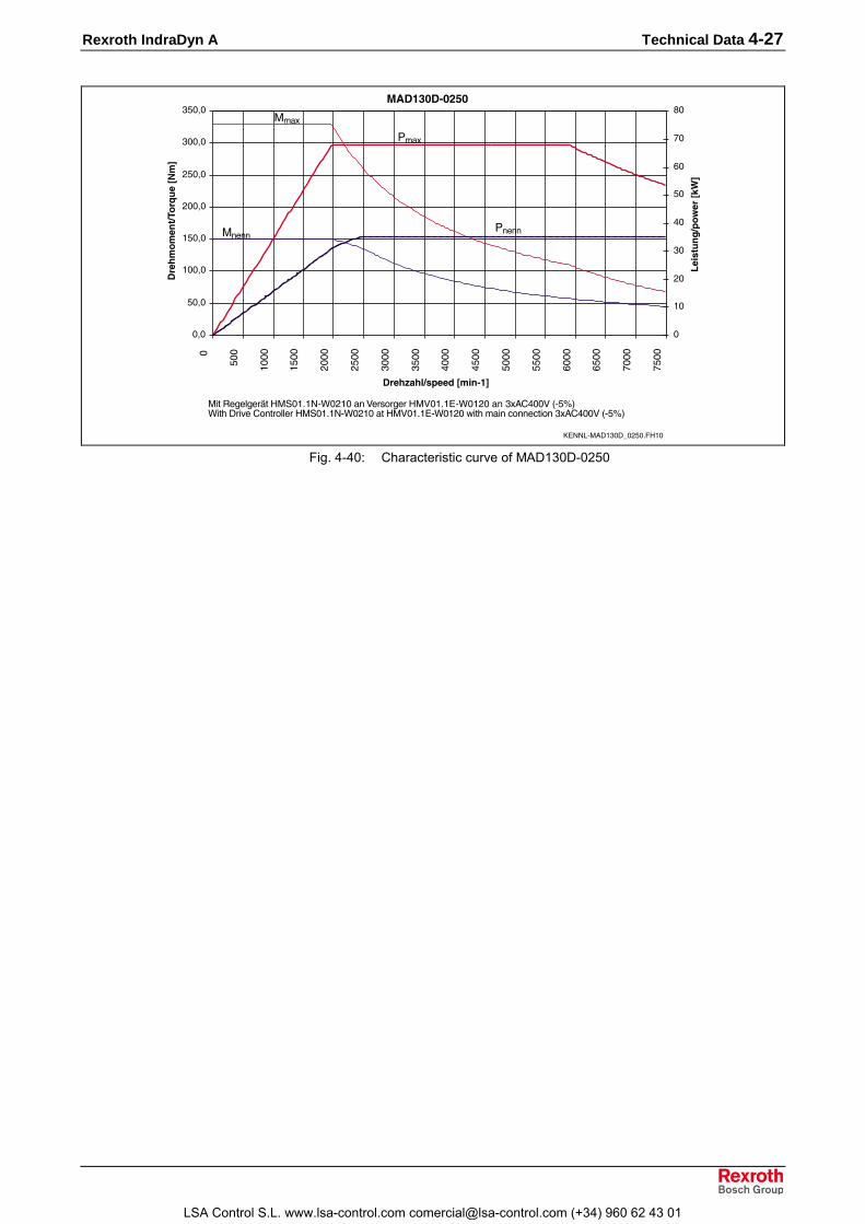
Rexroth IndraDyn A Technical Data 4-27
����&����$��
�+�
$�+�
���+�
�$�+�
)��+�
)$�+�
���+�
�$�+�
�
$��
����
�$��
)���
)$��
����
�$��
%���
%$��
$���
$$��
����
�$��
,���
,$��
��� ��������������
�����������������
�
��
)�
��
%�
$�
��
,�
-�
������ ���!
��"#
�
���
�����
&��
&����
����./�01���1��)$������
���3��4��5���������/(�)����6��7������6�����/(��)���� 08%��69/$�:(��"1����8�����44����������/(�)������6�����/(��)�;��"����<����<����� 08%��69/$�:
Fig. 4-40: Characteristic curve of MAD130D-0250
LSA Control S.L. www.lsa-control.com [email protected] (+34) 960 62 43 01

4-28 Technical Data Rexroth IndraDyn A
4.9 Technical Data Sheet for MAD160B
Description Symbol Unit MAD160B
Motor data 1)Winding 0050 0100 0150 0200Rated torque Mnenn Nm 210 200 185 160Rated speed nnenn rpm 500 1000 1500 2000Rated power Pnenn kW 11 20.9 29.1 33.5Rated current Inenn A 26.1 43.5 55.6 75.8Continuous torque at standstill Mn1 Nm - 210 200 170Derating speed n1 rpm - 500 1000 1500Continuous current at standstill In1 A - 45 58.7 80.9Maximum speed Mmax Nm 484 461 440 375Torque constant at 20°C KM_nenn Nm/A 10.96 5.47 4.06 2.54Min. cross section of power cable 2) A mm² 4 10 16 25Number of pole pairs p 2Rotor moment of inertia 3) Jrot kgm² 0.24Mass of motor 4) m kg 197
- Standard nmax rpm 3000 6000- coupling attachment nmax rpm 3000 4200- reinforced nmax rpm 3000 6000
Maximumspeed withbearing...
- High-speed nmax rpm not availableThermal time constant Tth min 60Duty cycle time (S6-44%) TC min i.p.Noise level 5) pSchall dB(A) 75 (+3)Permissible ambient temperature Tum °C 0....+40Permissible storage and transporttemperature Tlager °C -20....+80
Insulation class according to DINVDE 0530-1 F
International Protection class IP65
Holding brake (optional) Electrically-clamped Electrically-released Electrical-released- reinforced
Transmittable torque M4 Nm 100 240Connection voltage UBr V DC 24 ± 10 %Rated current IBr A 1.8 2.0 1.87Moment of inertia JBr kgm² 0.0065 0.0188Max. permissible braking energy Wmax Ws 40000 70000Disengagement time t2 ms 100 190 300Engagement time t1 ms 85 12 30Mass of brake m kg 20 25
Blower Axial blower
Air current B → Ablowing
Connection voltage UN V 3 x 400V ± 15 %, 50/60 Hz .... 3 x 480V ± 10 %, 50/60 HzPower consumption SN VA 132 .... 175Blower current 6) IN A 0.19 .... 0.21Average air flowrate V m³/h 10001) Values determined according to IEC 60034-1. Current and voltage specified as root-mean-square values.2) Rated for cable assemblies with current carrying capacity according to VDE0298-4 (1992) and installation type B2
according to EN 60204-1 (1993) at 40°C ambient temperature.3) Values without holding brake.4) Values without holding brake, with blower.5) at 1m distance, with PWM = 4 kHz6) From IN + 20%, blowers should be monitored.
Fig. 4-41: Data Sheet MAD160B
LSA Control S.L. www.lsa-control.com [email protected] (+34) 960 62 43 01

Rexroth IndraDyn A Technical Data 4-29
Characteristic Curve of MAD160B
����'�������
�+�
���+�
)��+�
���+�
%��+�
$��+�
���+�
�
$��
����
�$��
)���
)$��
����
��� ��������������
�����������������
�
$
��
�$
)�
)$
������ ���!
��"#
�
���
�����
&��
&����
����./�01���2���$������
���3��4��5���������/(��$%��6��7������6�����/(��)���� 08%��69/$�:(��"1����8�����44����������/(��$%����6�����/(��)�;��"����<����<����� 08%��69/$�:
Fig. 4-42: Characteristic curve of MAD160B-0050
����'�������
�+�
$�+�
���+�
�$�+�
)��+�
)$�+�
���+�
�$�+�
%��+�
%$�+�
$��+�
�
$��
����
�$��
)���
)$��
����
�$��
%���
%$��
$���
$$��
����
��� ��������������
�����������������
�
$
��
�$
)�
)$
��
�$
%�
%$
������ ���!
��"#
�
���
�����
&��
&����
����./�01���2����������
���3��4��5���������/(��$���6��7������6�����/(��)���� 08%��69/$�:(��"1����8�����44����������/(��$�����6�����/(��)�;��"����<����<����� 08%��69/$�:
Fig. 4-43: Characteristic curve of MAD160B-0100
LSA Control S.L. www.lsa-control.com [email protected] (+34) 960 62 43 01

4-30 Technical Data Rexroth IndraDyn A
����'�������
�+�
$�+�
���+�
�$�+�
)��+�
)$�+�
���+�
�$�+�
%��+�
%$�+�
$��+�
�
$��
����
�$��
)���
)$��
����
�$��
%���
%$��
$���
$$��
����
��� ��������������
�����������������
�
��
)�
��
%�
$�
��
,�
������ ���!
��"#
�
���
�����
&��
&����
����./�01���2���$������
���3��4��5���������/(��$���6��7������6�����/(��)���� 08%��69/$�:(��"1����8�����44����������/(��$�����6�����/(��)�;��"����<����<����� 08%��69/$�:
Fig. 4-44: Characteristic curve of MAD160B-0150
����'����$��
�+�
$�+�
���+�
�$�+�
)��+�
)$�+�
���+�
�$�+�
%��+�
�
$��
����
�$��
)���
)$��
����
�$��
%���
%$��
$���
$$��
����
��� ��������������
�����������������
�
��
)�
��
%�
$�
��
,�
-�
������ ���!
��"#
�
���
�����
&��
&����
����./�01���2��)�������
���3��4��5���������/(�)����6��7������6�����/(��)���� 08%��69/$�:(��"1����8�����44����������/(�)������6�����/(��)�;��"����<����<����� 08%��69/$�:
Fig. 4-45: Characteristic curve of MAD160B-0200
LSA Control S.L. www.lsa-control.com [email protected] (+34) 960 62 43 01

Rexroth IndraDyn A Technical Data 4-31
4.10 Technical Data Sheet for MAD160C
Description Symbol Unit MAD160C
Motor data 1)Winding 0050 0100 0150 0200Rated torque Mnenn Nm 240 225 215 210Rated speed nnenn rpm 500 1000 1500 2000Rated power Pnenn kW 12.6 23.6 33.8 44Rated current Inenn A 27.6 52.6 75.3 93.9Continuous torque at standstill Mn1 Nm - 240 225 225Derating speed n1 rpm - 500 1000 1500Continuous current at standstill In1 A - 55.2 77.8 100Maximum speed Mmax Nm 528 527 496 494Torque constant at 20°C KM_nenn Nm/A 9.95 4.97 3.36 2.63Min. cross section of power cable 2) A mm² 6 16 25 25Number of pole pairs p 2Rotor moment of inertia 3) Jrot kgm² 0.311Mass of motor 4) m kg 233
- Standard nmax rpm 3000 6000- coupling attachment nmax rpm 3000 4200- reinforced nmax rpm 3000 6000
Maximumspeed withbearing...
- High-speed nmax rpm not availableThermal time constant Tth min 70Duty cycle time (S6-44%) TC min i.p.Noise level 5) pSchall dB(A) 75 (+3)Permissible ambient temperature Tum °C 0....+40Permissible storage and transporttemperature Tlager °C -20....+80
Insulation class according to DINVDE 0530-1 F
International Protection class IP65
Holding brake (optional) Electrically-clamped Electrically-released
Electrically-released -reinforced
Transmittable torque M4 Nm 100 240Connection voltage UBr V DC 24 ± 10 %Rated current IBr A 1.8 2.0 1.87Moment of inertia JBr kgm² 0.0065 0.0188Max. permissible braking energy Wmax Ws 40000 70000Disengagement time t2 ms 100 190 300Engagement time t1 ms 85 12 30Mass of brake m kg 20 25
Blower Axial blower
Air current B → Ablowing
Connection voltage UN V 3 x 400V ± 15 %, 50/60 Hz .... 3 x 480V ± 10 %, 50/60 HzPower consumption SN VA 132 .... 175Blower current 6) IN A 0.19 .... 0.21Average air flowrate V m³/h 10001) Values determined according to IEC 60034-1. Current and voltage specified as root-mean-square values.2) Rated for cable assemblies with current carrying capacity according to VDE0298-4 (1992) and installation type B2
according to EN 60204-1 (1993) at 40°C ambient temperature.3) Values without holding brake.4) Values without holding brake, with blower.5) at 1m distance, with PWM = 4 kHz6) From IN + 20%, blowers should be monitored.
Fig. 4-46: Data Sheet MAD160C
LSA Control S.L. www.lsa-control.com [email protected] (+34) 960 62 43 01

4-32 Technical Data Rexroth IndraDyn A
Characteristic Curves of MAD160C
����'�%�����
�+�
���+�
)��+�
���+�
%��+�
$��+�
���+�
�
$��
����
�$��
)���
)$��
����
��� ��������������
�����������������
�
$
��
�$
)�
)$
������ ���!
��"#
�
���
�����
&��
&����
����./�01���8���$������
���3��4��5���������/(��,���6��7������6�����/(��)���� 08%��69/$�:(��"1����8�����44����������/(��,�����6�����/(��)�;��"����<����<����� 08%��69/$�:
Fig. 4-47: Characteristic curve of MAD160C-0050
����'�%�����
�+�
���+�
)��+�
���+�
%��+�
$��+�
���+�
�
$��
����
�$��
)���
)$��
����
�$��
%���
%$��
$���
$$��
����
��� ��������������
�����������������
�
$
��
�$
)�
)$
��
�$
%�
%$
$�
������ ���!��"#
�
���
�����
&��
&����
����./�01���8����������
���3��4��5���������/(��$���6��7������6�����/(��)���� 08%��69/$�:(��"1����8�����44����������/(��$�����6�����/(��)�;��"����<����<����� 08%��69/$�:
Fig. 4-48: Characteristic curve of MAD160C-0100
LSA Control S.L. www.lsa-control.com [email protected] (+34) 960 62 43 01

Rexroth IndraDyn A Technical Data 4-33
����'�%�����
�+�
���+�
)��+�
���+�
%��+�
$��+�
���+�
�
$��
����
�$��
)���
)$��
����
�$��
%���
%$��
$���
$$��
����
��� ��������������
�����������������
�
��
)�
��
%�
$�
��
,�
������ ���!
��"#
�
���
�����
&��
&����
����./�01���8���$������
���3��4��5���������/(�)����6��7������6�����/(��)���� 08%��69/$�:(��"1����8�����44����������/(�)������6�����/(��)�;��"����<����<����� 08%��69/$�:
Fig. 4-49: Characteristic curve of MAD160C-0150
����'�%��$��
�+�
���+�
)��+�
���+�
%��+�
$��+�
���+�
�
$��
����
�$��
)���
)$��
����
�$��
%���
%$��
$���
$$��
����
��� ��������������
�����������������
�
��
)�
��
%�
$�
��
,�
-�
=�
���
������ ���!
��"#
�
���
�����
&��
&����
����./�01���8��)�������
���3��4��5���������/(�)����6��7������6�����/(��)���� 08%��69/$�:(��"1����8�����44����������/(�)������6�����/(��)�;��"����<����<����� 08%��69/$�:
Fig. 4-50: Characteristic curve of MAD160C-0200
LSA Control S.L. www.lsa-control.com [email protected] (+34) 960 62 43 01

4-34 Technical Data Rexroth IndraDyn A
4.11 Technical Data Sheet for MAD180C
Description Symbol Unit MAD180C
Motor data 1)Winding 0050 0100 0150 0200Rated torque Mnenn Nm 325 300 270 250Rated speed nnenn rpm 500 1000 1500 2000Rated power Pnenn kW 18.8 34.6 47.1 52.4Rated current Inenn A 41.4 77.4 108.2 104.6Continuous torque at standstill Mn1 Nm - 325 300 270Derating speed n1 rpm - 500 1000 1500Continuous current at standstill In1 A - 82.9 116.2 110Maximum speed Mmax Nm 715 792 658 594Torque constant at 20°C KM_nenn Nm/A 9.77 4.88 3.25 3.01Min. cross section of power cable 2) A mm² 10 25 35 35Number of pole pairs p 2Rotor moment of inertia 3) Jrot kgm² 0.458Mass of motor 4) m kg 334
- Standard nmax rpm 3000 6000- coupling attachment nmax rpm 3000 4200- reinforced nmax rpm 3000 6000
Maximumspeed withbearing...
- High-speed nmax rpm not availableThermal time constant Tth min 60Duty cycle time (S6-44%) TC min i.p.Noise level 5) pSchall dB(A) 78 (+3)Permissible ambient temperature Tum °C 0....+40Permissible storage and transporttemperature Tlager °C -20....+80
Insulation class according to DINVDE 0530-1 F
International Protection class IP65
Holding brake (optional) Electrically-clamped Electrically- releasedTransmittable torque M4 Nm 300 240Connection voltage UBr V DC 24 ± 10 %Rated current IBr A 2 1.87Moment of inertia JBr kgm² 0.0188Max. permissible braking energy Wmax Ws 70000Disengagement time t2 ms 90 300Engagement time t1 ms 150 30Mass of brake m kg 25
Blower Axial blower
Air current B → Ablowing
Connection voltage UN V 3 x 400V ± 15 %, 50/60 Hz .... 3 x 480V ± 10 %, 50/60 HzPower consumption SN VA 242 .... 382Blower current 6) IN A 0.35 .... 0.46Average air flowrate V m³/h 15001) Values determined according to IEC 60034-1. Current and voltage specified as root-mean-square values.2) Rated for cable assemblies with current carrying capacity according to VDE0298-4 (1992) and installation type B2
according to EN 60204-1 (1993) at 40°C ambient temperature.3) Werte ohne Haltebremse.4) Values without holding brake, with blower.5) at 1m distance, with PWM = 4 kHz6) From IN + 20%, blowers should be monitored.
Fig. 4-51: Data Sheet MAD180C
LSA Control S.L. www.lsa-control.com [email protected] (+34) 960 62 43 01

Rexroth IndraDyn A Technical Data 4-35
Characteristic Curves of MAD180C
����(�%�����
�+�
���+�
)��+�
���+�
%��+�
$��+�
���+�
,��+�
-��+�
�
$��
����
�$��
)���
)$��
����
��� ��������������
�����������������
�
$
��
�$
)�
)$
��
�$
������ ���!
��"#
�
���
�����
&��
&����
����./�01�-�8���$������
���3��4��5���������/(��$���6��7������6�����/(��)���� 08%��69/$�:(��"1����8�����44����������/(��$�����6�����/(��)�;��"����<����<����� 08%��69/$�:
Fig. 4-52: Characteristic curve of MAD180C-0050
����(�%�����
�+�
���+�
)��+�
���+�
%��+�
$��+�
���+�
,��+�
-��+�
=��+�
�
$��
����
�$��
)���
)$��
����
�$��
%���
%$��
$���
$$��
����
��� ��������������
�����������������
�
��
)�
��
%�
$�
��
,�
-�
������ ���!
��"#
�
���
�����
&��
&����
����./�01�-�8����������
���3��4��5���������/(�)����6��7������6�����/(��)���� 08%��69/$�:(��"1����8�����44����������/(�)������6�����/(��)�;��"����<����<����� 08%��69/$�:
Fig. 4-53: Characteristic curve of MAD180C-0100
LSA Control S.L. www.lsa-control.com [email protected] (+34) 960 62 43 01

4-36 Technical Data Rexroth IndraDyn A
����(�%�����
�+�
���+�
)��+�
���+�
%��+�
$��+�
���+�
,��+�
�
$��
����
�$��
)���
)$��
����
�$��
%���
%$��
$���
$$��
����
��� ��������������
�����������������
�
��
)�
��
%�
$�
��
,�
-�
=�
���
������ ���!
��"#
�
���
�����
&��
&����
����./�01�-�8���$������
���3��4��5���������/(�)����6��7������6�����/(��)���� 08%��69/$�:(��"1����8�����44����������/(�)������6�����/(��)�;��"����<����<����� 08%��69/$�:
Fig. 4-54: Characteristic curve of MAD180C-0150
����(�%��$��
�+�
���+�
)��+�
���+�
%��+�
$��+�
���+�
,��+�
�
$��
����
�$��
)���
)$��
����
�$��
%���
%$��
$���
$$��
����
��� ��������������
�����������������
�
)�
%�
��
-�
���
�)�
������ ���!
��"#
�
���
�����
&��
&����
����./�01�-�8��)�������
���3��4��5���������/(�)����6��7������6�����/(��)���� 08%��69/$�:(��"1����8�����44����������/(�)������6�����/(��)�;��"����<����<����� 08%��69/$�:
Fig. 4-55: Characteristic curve of MAD180C-0200
LSA Control S.L. www.lsa-control.com [email protected] (+34) 960 62 43 01

Rexroth IndraDyn A Technical Data 4-37
4.12 Technical Data Sheet for MAD180D
Description Symbol Unit MAD180D
Motor data 1)Winding 0050 0100 0150 0200Rated torque Mnenn Nm 390 370 340 300Rated speed nnenn rpm 500 1000 1500 2000Rated power Pnenn kW 20.4 38.7 53.4 62.8Rated current Inenn A 39.7 82.4 107.8 117.4Continuous torque at standstill Mn1 Nm - 410 360 350Derating speed n1 rpm - 500 1000 1500Continuous current at standstill In1 A - 90.0 112.3 132.6Maximum speed Mmax Nm 858 901 793 768Torque constant at 20°C KM_nenn Nm/A 11.31 5.66 3.77 2.92Min. cross section of power cable 2) A mm² 10 25 35 35Number of pole pairs p 2Rotor moment of inertia 3) Jrot kgm² 0.594Mass of motor 4) m kg 395
- Standard nmax rpm 3000 6000- coupling attachment nmax rpm 3000 4200- reinforced nmax rpm 3000 6000
Maximumspeed withbearing...
- High-speed nmax rpm not availableThermal time constant Tth min 70Duty cycle time (S6-44%) TC min i.p.Noise level 5) pSchall dB(A) 78 (+3)Permissible ambient temperature Tum °C 0....+40Permissible storage and transporttemperature Tlager °C -20....+80
Insulation class according to DINVDE 0530-1 F
International Protection class IP65
Holding brake (optional) Electrically-clamped Electrically-releasedTransmittable torque M4 Nm 300 240Connection voltage UBr V DC 24 ± 10 %Rated current IBr A 2 1.87Moment of inertia JBr kgm² 0.0188Max. permissible braking energy Wmax Ws 70000Disengagement time t2 ms 90 300Engagement time t1 ms 150 30Mass of brake m kg 25
Blower Axial blower
Air current B → Ablowing
Connection voltage UN V 3 x 400V ± 15 %, 50/60 Hz .... 3 x 480V ± 10 %, 50/60 HzPower consumption SN VA 242 .... 382Blower current 6) IN A 0.35 .... 0.46Average air flowrate V m³/h 15001) Values determined according to IEC 60034-1. Current and voltage specified as root-mean-square values.2) Rated for cable assemblies with current carrying capacity according to VDE0298-4 (1992) and installation type B2
according to EN 60204-1 (1993) at 40°C ambient temperature.3) Values without holding brake.4) Values without holding brake, with blower.5) at 1m distance, with PWM = 4 kHz6) From IN + 20%, blowers should be monitored.
Fig. 4-56: Data Sheet MAD180D
LSA Control S.L. www.lsa-control.com [email protected] (+34) 960 62 43 01

4-38 Technical Data Rexroth IndraDyn A
Characteristic Curves of MAD180D
����(�������
�+�
���+�
)��+�
���+�
%��+�
$��+�
���+�
,��+�
-��+�
=��+�
����+�
�
$��
����
�$��
)���
)$��
����
��� ��������������
�����������������
�
$
��
�$
)�
)$
��
�$
%�
������ ���!
��"#
�
���
�����
&��
&����
����./�01�-�1���$������
���3��4��5���������/(��$���6��7������6�����/(��)���� 08%��69/$�:(��"1����8�����44����������/(��$�����6�����/(��)�;��"����<����<����� 08%��69/$�:
Fig. 4-57: Characteristic curve of MAD180D-0050
����(�������
�+�
���+�
)��+�
���+�
%��+�
$��+�
���+�
,��+�
-��+�
=��+�
����+�
�
$��
����
�$��
)���
)$��
����
�$��
%���
%$��
$���
$$��
����
��� ��������������
�����������������
�+�
��+�
)�+�
��+�
%�+�
$�+�
��+�
,�+�
-�+�
=�+�
������ ���!��"#
�
���
�����
&��
&����
����./�01�-�1����������
���3��4��5���������/(�)����6��7������6�����/(��)���� 08%��69/$�:(��"1����8�����44����������/(�)������6�����/(��)�;��"����<����<����� 08%��69/$�:
Fig. 4-58: Characteristic curve of MAD180D-0100
LSA Control S.L. www.lsa-control.com [email protected] (+34) 960 62 43 01

Rexroth IndraDyn A Technical Data 4-39
�01�-�1/��$�
�+�
���+�
)��+�
���+�
%��+�
$��+�
���+�
,��+�
-��+�
=��+�
�
$��
����
�$��
)���
)$��
����
�$��
%���
%$��
$���
$$��
����
1��">�"4*7��� ����/��
1��"�
����
�*!��?@
���
��
�
)�
%�
��
-�
���
�)�
.��7�@�
*��;
���'
(�
���
�����
&��
&����
����./�01�-�1���$������
���3��4��5���������/(�)����6��7������6�����/(��)���� 08%��69/$�:(��"1����8�����44����������/(�)������6�����/(��)�;��"����<����<����� 08%��69/$�:
Fig. 4-59: Characteristic curve of MAD180D-0150
����(����$��
�+�
���+�
)��+�
���+�
%��+�
$��+�
���+�
,��+�
�
$��
����
�$��
)���
)$��
����
�$��
%���
%$��
$���
$$��
����
��� ��������������
�����������������
�
)�
%�
��
-�
���
�)�
�%�
������ ���!
��"#
�
���
�����
&��
&����
����./�01�-�1��)�������
���3��4��5���������/(�)����6��7������6�����/(��)���� 08%��69/$�:(��"1����8�����44����������/(�)������6�����/(��)�;��"����<����<����� 08%��69/$�:
Fig. 4-60: Characteristic curve of MAD180D-0200
LSA Control S.L. www.lsa-control.com [email protected] (+34) 960 62 43 01

4-40 Technical Data Rexroth IndraDyn A
4.13 Technical Data Sheet for MAF100B
Description Symbol Unit MAF100B
Motor data 1)Winding 0050 0100 0150 0200 0250Rated torque Mnenn Nm 50 46 42 38 33Rated speed nnenn rpm 500 1000 1500 2000 2500Rated power Pnenn kW 2.6 4.8 6.6 8.0 8.6Rated current Inenn A 8.5 14.3 18.1 23.9 26Continuous torque at standstill Mn1 Nm - 50 46 42 38Derating speed n1 rpm - 500 1000 1500 2000Continuous current at standstill In1 A - 17.9 22.7 25.8 26.5Maximum speed Mmax Nm 110 110 101 92 84Torque constant at 20°C KM_nenn Nm/A 6.68 3.73 2.76 1.84 1.49Min. cross section of power cable 2) A mm² 2.5 2.5 4 4 4Number of pole pairs p 3Moment of inertia of rotor 3) Jrot kgm² 0.019Motor mass 3) m kg 56
- Standard nmax rpm 3000 6000 9000- coupling attachment nmax rpm 3000 6000 6300- reinforced nmax rpm not available
Maximumspeed withbearing...
- High-speed nmax rpm 3000 6000 9000 11000 6)Thermal time constant Tth min 10Duty cycle time (S6-44%) TC min i.p.Noise level 4) pSchall dB(A) 70 (+3)Permissible ambient temperature Tum °C 0....+40Permissible storage and transporttemperature Tlager °C -20....+80
Insulation class according to DIN VDE0530-1 F
International Protection class IP65
Liquid cooling 5)Power loss to be dissipated PV kW 1.0
Cooling agent inlet Tein °C +10....+40Cooling agenttemperature Permissible increase at PV ∆Tdiff K 10
without fast coupling ∆pdiff bar 0.4Decompres-sion at Qmin with fast coupling ∆pdiff bar 0.8Required flow of coolant at PV Qmin l/min 1.45Permissible inlet pressure pmax bar 3
Holding brake (optional) Electrically-clamped Electrically-releasedTransmittable torque M4 Nm 30 24Connection voltage UBr V DC 24 ± 10 %Rated current IBr A 0.9 1.1Moment of inertia JBr kgm² 0.00056Max. permissible braking energy Wmax Ws 20000Disengagement time t2 ms 50 90Engagement time t1 ms 42 30Maximum speed of brake nBr_max rpm 10000 10000Mass of brake m kg 2 1.61) Values determined according to IEC 60034-1. Current and voltage specified as root-mean-square values2) Rated for cable assemblies with current carrying capacity according to VDE0298-4 (1992) and installation type B2
according to EN 60204-1 (1993) at 40°C ambient temperature.3) Values without holding brake.4) in 1 m distance, with PWN = 4kHz5) Data refer to water as a cooling agent. If using other coolant, re-calculate the data.
Observe instructions on coolant inlet temperature in chapter 9.6) Value is without a holding brake. This value may be limited by a holding brake.
Fig. 4-61: Data sheet MAF100B
LSA Control S.L. www.lsa-control.com [email protected] (+34) 960 62 43 01

Rexroth IndraDyn A Technical Data 4-41
Characteristic Curves of MAF100B
��)���������
�+�
)�+�
%�+�
��+�
-�+�
���+�
�)�+�
�
$��
����
�$��
)���
)$��
����
��� ��������������
�����������������
�+�
�+�
)+�
�+�
%+�
$+�
�+�
������ ���!
��"#
�
���
�����
&��
&����
����./�0����2���$������
���3��4��5���������/(������6��7������6�����/(��)���� 08%��69/$�:(��"1����8�����44����������/(��������6�����/(��)�;��"����<����<����� 08%��69/$�:
Fig. 4-62: Characteristic curve of MAF100B-0050
��)���������
�+�
)�+�
%�+�
��+�
-�+�
���+�
�)�+�
�
$��
����
�$��
)���
)$��
����
�$��
%���
%$��
$���
$$��
����
��� ��������������
�����������������
�
�
)
�
%
$
�
,
-
������ ���!
��"#
�
���
�����
&��
&����
����./�0����2����������
���3��4��5���������/(��$%��6��7������6�����/(��)���� 08%��69/$�:(��"1����8�����44����������/(��$%����6�����/(��)�;��"����<����<����� 08%��69/$�:
Fig. 4-63: Characteristic curve of MAF100B-0100
LSA Control S.L. www.lsa-control.com [email protected] (+34) 960 62 43 01

4-42 Technical Data Rexroth IndraDyn A
��)���������
�+�
)�+�
%�+�
��+�
-�+�
���+�
�)�+�
�
$��
����
�$��
)���
)$��
����
�$��
%���
%$��
$���
$$��
����
�$��
,���
,$��
-���
-$��
=���
��� ��������������
�����������������
�
)
%
�
-
��
�)
������ ���!
��"#
�
���
�����
&��
&����
����./�0����2���$������
���3��4��5���������/(��$%��6��7������6�����/(��)���� 08%��69/$�:(��"1����8�����44����������/(��$%����6�����/(��)�;��"����<����<����� 08%��69/$�:
Fig. 4-64: Characteristic curve of MAF100B-0150
��)������$��
�+�
��+�
)�+�
��+�
%�+�
$�+�
��+�
,�+�
-�+�
=�+�
���+�
�
$��
����
�$��
)���
)$��
����
�$��
%���
%$��
$���
$$��
����
�$��
,���
,$��
-���
-$��
=���
��� ��������������
�����������������
�
)
%
�
-
��
�)
�%
��
������ ���!
��"#
�
���
�����
&��
&����
����./�0����2��)�������
���3��4��5���������/(��$%��6��7������6�����/(��)���� 08%��69/$�:(��"1����8�����44����������/(��$%����6�����/(��)�;��"����<����<����� 08%��69/$�:
Fig. 4-65: Characteristic curve of MAF100B-0200
LSA Control S.L. www.lsa-control.com [email protected] (+34) 960 62 43 01

Rexroth IndraDyn A Technical Data 4-43
��)������$��
�+�
��+�
)�+�
��+�
%�+�
$�+�
��+�
,�+�
-�+�
=�+�
�
$��
����
�$��
)���
)$��
����
�$��
%���
%$��
$���
$$��
����
�$��
,���
,$��
-���
-$��
=���
��� ��������������
�����������������
�
)
%
�
-
��
�)
�%
��
�-
)�
������ ���!
��"#
�
���
�����
&��
&����
����./�0����2��)$������
���3��4��5���������/(��$%��6��7������6�����/(��)���� 08%��69/$�:(��"1����8�����44����������/(��$%����6�����/(��)�;��"����<����<����� 08%��69/$�:
Fig. 4-66: Characteristic curve of MAF100B-0250
LSA Control S.L. www.lsa-control.com [email protected] (+34) 960 62 43 01

4-44 Technical Data Rexroth IndraDyn A
4.14 Technical Data Sheet for MAF100C Description Symbol Unit MAF100C
Motor data 1)Winding 0050 0100 0150 0200 0250Rated torque Mnenn Nm 70 68 66 64 62Rated speed nnenn rpm 500 1000 1500 2000 2500Rated power Pnenn kW 3.9 7.5 10.4 13.4 16.2Rated current Inenn A 12.1 19 27.9 36.7 40.2Continuous torque at standstill Mn1 Nm - 70 68 66 64Derating speed n1 rpm - 500 1000 1500 2000Continuous current at standstill In1 A - 19.5 28.6 37.6 45Maximum speed Mmax Nm 154 154 149 145 138Torque constant at 20°C KM_nenn Nm/A 6.06 3.77 2.5 1.91 1.55Min. cross section of power cable 2) A mm² 2.5 2.5 4 6 10Number of pole pairs p 3Moment of inertia of rotor 3) Jrot kgm² 0.0284Mass 3) m kg 70
- Standard nmax rpm 3000 6000 9000- coupling attachment nmax rpm 3000 6000 6300- reinforced nmax rpm not available
Maximumspeed withbearing...
- High-speed nmax rpm 3000 6000 9000 11000 6)Thermal time constant Tth min 10Duty cycle time (S6-44%) TC min i.p.Noise level 4) pSchall dB(A) 70 (+3)Permissible ambient temperature Tum °C 0....+40Permissible storage and transporttemperature Tlager °C -20....+80
Insulation class according toDIN VDE 0530-1 F
International Protection class IP65
Liquid cooling 5)Power loss to be dissipated PV kW 1.1 1.2 1.3 1.9
Cooling agent inlet Tein °C +10....+40Cooling agenttemperature Permissible increase at PV ∆Tdiff K 10
without fast coupling ∆pdiff bar 0.6Decompres-sion at Qmin with fast coupling ∆pdiff bar 1.2Required flow of coolant at PV Qmin l/min 1.6 1.75 1.9 2.8Permissible inlet pressure pmax bar 3
Holding brake (optional) Electrically-clamped Electrically-releasedTransmittable torque M4 Nm 30 24Connection voltage UBr V DC 24 ± 10 %Rated current IBr A 0.9 1.1Moment of inertia JBr kgm² 0.00056Max. permissible braking energy Wmax Ws 20000Disengagement time t2 ms 50 90Engagement time t1 ms 42 30Maximum speed of brake nBr_max rpm 10000 10000Mass m kg 2 1.61) Values determined according to IEC 60034-1. Current and voltage specified as root-mean-square values.2) Rated for cable assemblies with current carrying capacity according to VDE0298-4 (1992) and installation type B2
according to EN 60204-1 (1993) at 40°C ambient temperature.3) Values without holding brake.4) in 1 m distance, with PWN = 4kHz5) Data refer to water as a cooling agent. If using other coolant, re-calculate the data.
Observe instructions on coolant inlet temperature in chapter 9.6) Value is without a holding brake. This value may be limited by a holding brake.
Fig. 4-67: Data sheet MAF100C
LSA Control S.L. www.lsa-control.com [email protected] (+34) 960 62 43 01

Rexroth IndraDyn A Technical Data 4-45
Characteristic Curves of MAF100B
��)���%�����
�+�
)�+�
%�+�
��+�
-�+�
���+�
�)�+�
�%�+�
���+�
�-�+�
�
$��
����
�$��
)���
)$��
����
��� ��������������
�����������������
�
�
)
�
%
$
�
������ ���!
��"#
�
���
�����
&��
&����
����./�0����8���$������
���3��4��5���������/(������6��7������6�����/(��)���� 08%��69/$�:(��"1����8�����44����������/(��������6�����/(��)�;��"����<����<����� 08%��69/$�:
Fig. 4-134: Characteristic curve of MAF100C-0050
��)���%�����
�+�
)�+�
%�+�
��+�
-�+�
���+�
�)�+�
�%�+�
���+�
�-�+�
�
$��
����
�$��
)���
)$��
����
�$��
%���
%$��
$���
$$��
����
��� ��������������
�����������������
�
)
%
�
-
��
�)
������ ���!
��"#
�
���
�����
&��
&����
����./�0����8����������
���3��4��5���������/(��$%��6��7������6�����/(��)���� 08%��69/$�:(��"1����8�����44����������/(��$%����6�����/(��)�;��"����<����<����� 08%��69/$�:
Fig. 4-135: Characteristic curve of MAF100C-0100
LSA Control S.L. www.lsa-control.com [email protected] (+34) 960 62 43 01

4-46 Technical Data Rexroth IndraDyn A
��)���%�����
�+�
)�+�
%�+�
��+�
-�+�
���+�
�)�+�
�%�+�
���+�
�
$��
����
�$��
)���
)$��
����
�$��
%���
%$��
$���
$$��
����
�$��
,���
,$��
-���
-$��
=���
��� ��������������
�����������������
�
)
%
�
-
��
�)
�%
��
�-
)�
������ ���!
��"#
�
���
�����
&��
&����
����./�0����8���$������
���3��4��5���������/(��,���6��7������6�����/(��)���� 08%��69/$�:(��"1����8�����44����������/(��,�����6�����/(��)�;��"����<����<����� 08%��69/$�:
Fig. 4-136: Characteristic curve of MAF100C-0150
��)���%��$��
�+�
)�+�
%�+�
��+�
-�+�
���+�
�)�+�
�%�+�
���+�
�
$��
����
�$��
)���
)$��
����
�$��
%���
%$��
$���
$$��
����
�$��
,���
,$��
-���
-$��
=���
��� ��������������
�����������������
�
$
��
�$
)�
)$
��
������ ���!��"#
�
���
�����
&��
&����
����./�0����8��)�������
���3��4��5���������/(��$���6��7������6�����/(��)���� 08%��69/$�:(��"1����8�����44����������/(��$�����6�����/(��)�;��"����<����<����� 08%��69/$�:
Fig. 4-137: Characteristic curve of MAF100C-0200
LSA Control S.L. www.lsa-control.com [email protected] (+34) 960 62 43 01

Rexroth IndraDyn A Technical Data 4-47
��)���%��$��
�+�
$�+�
���+�
�$�+�
)��+�
)$�+�
���+�
�
$��
����
�$��
)���
)$��
����
�$��
%���
%$��
$���
$$��
����
�$��
,���
,$��
-���
-$��
=���
��� ��������������
�����������������
�
$
��
�$
)�
)$
��
�$
%�
%$
������ ���!
��"#
�
���
�����
&��
&����
����./�0����8��)$������
���3��4��5���������/(�)����6��7������6�����/(��)���� 08%��69/$�:(��"1����8�����44����������/(�)������6�����/(��)�;��"����<����<����� 08%��69/$�:
Fig. 4-138: Characteristic curve of MAF100C-0250
LSA Control S.L. www.lsa-control.com [email protected] (+34) 960 62 43 01

4-48 Technical Data Rexroth IndraDyn A
4.15 Technical Data Sheet for MAF100DDescription Symbol Unit MAF100D
Motor data 1)Winding 0050 0100 0150 0200 0250Rated torque Mnenn Nm 88 84 79 80 75Rated speed nnenn rpm 500 1000 1500 2000 2500Rated power Pnenn kW 4.6 8.8 12.4 16.8 19.6Rated current Inenn A 14.5 25.1 32.7 43.1 45.8Continuous torque at standstill Mn1 Nm - 88 84 83 80Derating speed n1 rpm - 500 1000 1500 2000Continuous current at standstill In1 A - 26.1 34.3 44.4 56.1Maximum speed Mmax Nm 193 194 185 182 177Torque constant at 20°C KM_nenn Nm/A 6.79 3.78 2.77 2.08 1.55Min. cross section of power cable 2) A mm² 2.5 4 6 10 16Number of pole pairs p 3Moment of inertia 3) Jrot kgm² 0.032Mass 3) m kg 88
- Standard nmax rpm 3000 6000 9000- coupling attachment nmax rpm 3000 6000 6300- reinforced nmax rpm not available
Maximumspeed withbearing...
- High-speed nmax rpm 3000 6000 9000 11000 6)Thermal time constant Tth min 10Duty cycle time (S6-44%) TC: min i.p.Noise level 4) pSchall dB(A) 70 (+3)Permissible ambient temperature Tum °C 0....+40Permissible storage and transporttemperature Tlager °C -20....+80
Insulation class according toDIN VDE 0530-1 F
International Protection class IP65
Liquid cooling 5)Power loss to be dissipated PV kW 1.4 1.45 1.5 1.55 1.9
Cooling agent inlet Tein °C +10....+40Cooling agenttemperature Permissible increase at PV ∆Tdiff K 10
without fast coupling ∆pdiff bar 1.0Decompres-sion at Qmin with fast coupling ∆pdiff bar 1.9Required flow of coolant at PV Qmin l/min 2 2.1 2.2 2.3 2.8Permissible inlet pressure pmax bar 3
Holding brake (optional) Electrically-clamped Electrically-releasedTransmittable torque M4 Nm 30 24Connection voltage UBr V DC 24 ± 10 %Rated current IBr A 0.9 1.1Moment of inertia JBr kgm² 0.00056Max. permissible braking energy Wmax Ws 20000Disengagement time t2 ms 50 90Engagement time t1 ms 42 30Maximum speed of brake nBr_max rpm 10000 10000Mass m kg 2 1.61) Values determined according to IEC 60034-1. Current and voltage specified as root-mean-square values.2) Rated for cable assemblies with current carrying capacity according to VDE0298-4 (1992) and installation type B2
according to EN 60204-1 (1993) at 40°C ambient temperature.(1993) bei 40 °C Umgebungstemperatur.
3) Values without holding brake.4) in 1 m distance, with PWN = 4kHz5) Data refer to water as a cooling agent. If using other coolant, re-calculate the data.
Observe instructions on coolant inlet temperature in chapter 9.8.6) Value is without a holding brake. This value may be limited by a holding brake.
Fig. 4-139: Data Sheet MAF100D
LSA Control S.L. www.lsa-control.com [email protected] (+34) 960 62 43 01

Rexroth IndraDyn A Technical Data 4-49
Characteristic Curves of MAF100D
��)���������
�+�
$�+�
���+�
�$�+�
)��+�
)$�+�
�
$��
����
�$��
)���
)$��
����
��� ��������������
�����������������
�
�
)
�
%
$
�
,
������ ���!
��"#
�
���
�����
&��
&����
����./�0����1���$������
���3��4��5���������/(������6��7������6�����/(��)���� 08%��69/$�:(��"1����8�����44����������/(��������6�����/(��)�;��"����<����<����� 08%��69/$�:
Fig. 4-140: Characteristic curve of MAF100D-0050
��)���������
�+�
$�+�
���+�
�$�+�
)��+�
)$�+�
�
$��
����
�$��
)���
)$��
����
�$��
%���
%$��
$���
$$��
����
��� ��������������
�����������������
�
)
%
�
-
��
�)
�%
��
�-
������ ���!
��"#
�
���
�����
&��
&����
����./�0����1����������
���3��4��5���������/(��$%��6��7������6�����/(��)���� 08%��69/$�:(��"1����8�����44����������/(��$%����6�����/(��)�;��"����<����<����� 08%��69/$�:
Fig. 4-141: Characteristic curve of MAF100D-0100
LSA Control S.L. www.lsa-control.com [email protected] (+34) 960 62 43 01

4-50 Technical Data Rexroth IndraDyn A
��)���������
�+�
)�+�
%�+�
��+�
-�+�
���+�
�)�+�
�%�+�
���+�
�-�+�
)��+�
�
$��
����
�$��
)���
)$��
����
�$��
%���
%$��
$���
$$��
����
�$��
,���
,$��
-���
-$��
=���
��� ��������������
�����������������
�
$
��
�$
)�
)$
������ ���!
��"#
�
���
�����
&��
&����
����./�0����1���$������
���3��4��5���������/(��,���6��7������6�����/(��)���� 08%��69/$�:(��"1����8�����44����������/(��,�����6�����/(��)�;��"����<����<����� 08%��69/$�:
Fig. 4-142: Characteristic curve of MAF100D-0150
��)������$��
�+�
)�+�
%�+�
��+�
-�+�
���+�
�)�+�
�%�+�
���+�
�-�+�
)��+�
�
$��
����
�$��
)���
)$��
����
�$��
%���
%$��
$���
$$��
����
�$��
,���
,$��
-���
-$��
=���
��� ��������������
�����������������
�
$
��
�$
)�
)$
��
�$
������ ���!��"#
�
���
�����
&��
&����
����./�0����1��)�������
���3��4��5���������/(��$���6��7������6�����/(��)���� 08%��69/$�:(��"1����8�����44����������/(��$�����6�����/(��)�;��"����<����<����� 08%��69/$�:
Fig. 4-143: Characteristic curve of MAF100D-0200
LSA Control S.L. www.lsa-control.com [email protected] (+34) 960 62 43 01

Rexroth IndraDyn A Technical Data 4-51
��)������$��
�+�
$�+�
���+�
�$�+�
)��+�
)$�+�
���+�
�$�+�
%��+�
�
$��
����
�$��
)���
)$��
����
�$��
%���
%$��
$���
$$��
����
�$��
,���
,$��
-���
-$��
=���
��� ��������������
�����������������
�
��
)�
��
%�
$�
��
������ ���!
��"#
�
���
�����
&��
&����
����./�0����1��)$������
���3��4��5���������/(�)����6��7������6�����/(��)���� 08%��69/$�:(��"1����8�����44����������/(�)������6�����/(��)�;��"����<����<����� 08%��69/$�:
Fig. 4-144: Characteristic curve of MAF100D-0250
LSA Control S.L. www.lsa-control.com [email protected] (+34) 960 62 43 01

4-52 Technical Data Rexroth IndraDyn A
4.16 Technical Data sheet for MAF130B Description Symbol Unit MAF130B
Motor data 1)Winding 0050 0100 0150 0200 0250Rated torque Mnenn Nm 116 112 115 100 90Rated speed nnenn rpm 500 1000 1500 2000 2500Rated power Pnenn kW 6.1 11.7 18.1 20.9 23.6Rated current Inenn A 14.7 28.4 43.7 51.7 55.5Continuous torque at standstill Mn1 Nm - 116 120 108 100Derating speed n1 rpm - 500 1000 1500 2000Continuous current at standstill In1 A - 29.3 45.3 55.2 56.1Maximum speed Mmax Nm 255 255 264 238 221Torque constant at 20°C KM_nenn Nm/A 8.46 4.25 2.83 2.12 1.83Min. cross section of power cable 2) A mm² 6 6 10 10 16Number of pole pairs p 3Moment of inertia of rotor 3) Jrot kgm² 0.079Motor mass 3) m kg 93
- Standard nmax rpm 3000 6000 7500- coupling attachment nmax rpm 3000 5250- reinforced nmax rpm 3000 6000 7500
Maximumspeed withbearing...
- High-speed nmax rpm 3000 6000 9000 6) 10000 6)Thermal time constant Tth min 15Duty cycle time (S6-44%) TC min i.p.Noise level 4) pSchall dB(A) 70 (+3)Permissible ambient temperature Tum °C 0....+40Permissible storage and transporttemperature Tlager °C -20....+80
Insulation class according toDIN VDE 0530-1 F
International Protection class IP65
Liquid cooling 5)Power loss to be dissipated PV kW 1.8 1.9 2 2.1 2.2
Cooling agent inlet Tein °C +10....+40Cooling agenttemperature Permissible increase at PV ∆Tdiff K 10
without fast coupling ∆pdiff bar 0.3Decompressionat Qmin with fast coupling ∆pdiff bar 0.6Required flow of coolant at PV Qmin l/min 2.7 2.8 2.9 3.1 3.2max. system pressure pmax bar 3
Holding brake (optional) Electrically-clamped Electrically-releasedTransmittable torque M4 Nm 100 80Connection voltage UBr V DC 24 ± 10 %Rated current IBr A 1.5 1.6Moment of inertia JBr kgm² 0.002Max. permissible braking energy Wmax Ws 30000Disengagement time t2 ms 65 140Engagement time t1 ms 110 50Maximum speed of brake nBr_max rpm 8000 8000Mass m kg 81) Values determined according to IEC 60034-1. Current and voltage specified as root-mean-square values.2) Rated for cable assemblies with current carrying capacity according to VDE0298-4 (1992) and installation type B2
according to EN 60204-1 (1993) at 40°C ambient temperature.3) Values without holding brake.4) in 1 m distance, with PWN = 4kHz5) Data refer to water as a cooling agent. If using other coolant, re-calculate the data.
Observe instructions on coolant inlet temperature in chapter 9.6) Value is without a holding brake. This value may be limited by a holding brake.
Fig. 4-68: Data Sheet MAF130B
LSA Control S.L. www.lsa-control.com [email protected] (+34) 960 62 43 01

Rexroth IndraDyn A Technical Data 4-53
Characteristic Curves of MAF130B
��)�&�������
�+�
$�+�
���+�
�$�+�
)��+�
)$�+�
���+�
�
$��
����
�$��
)���
)$��
����
��� ��������������
�����������������
�
�
)
�
%
$
�
,
-
=
������ ���!
��"#
�
���
�����
&��
&����
����./�0����2���$������
���3��4��5���������/(������6��7������6�����/(��)���� 08%��69/$�:(��"1����8�����44����������/(��������6�����/(��)�;��"����<����<����� 08%��69/$�:
Fig. 4-69: Characteristic curve of MAF130B-0050
��)�&�������
�+�
$�+�
���+�
�$�+�
)��+�
)$�+�
���+�
�
$��
����
�$��
)���
)$��
����
�$��
%���
%$��
$���
$$��
����
��� ��������������
�����������������
�
$
��
�$
)�
)$
������ ���!
��"#
�
���
�����
&��
&����
����./�0����2����������
���3��4��5���������/(��,���6��7������6�����/(��)���� 08%��69/$�:(��"1����8�����44����������/(��,�����6�����/(��)�;��"����<����<����� 08%��69/$�:
Fig. 4-70: Characteristic curve of MAF130B-0100
LSA Control S.L. www.lsa-control.com [email protected] (+34) 960 62 43 01
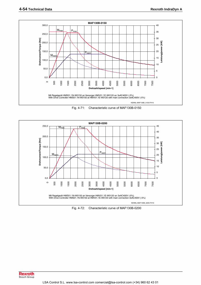
4-54 Technical Data Rexroth IndraDyn A
��)�&�������
�+�
$�+�
���+�
�$�+�
)��+�
)$�+�
���+�
�
$��
����
�$��
)���
)$��
����
�$��
%���
%$��
$���
$$��
����
�$��
,���
,$��
��� ��������������
�����������������
�
$
��
�$
)�
)$
��
�$
%�
������ ���!
��"#
�
���
�����
&��
&����
����./�0����2���$������
���3��4��5���������/(��$���6��7������6�����/(��)���� 08%��69/$�:(��"1����8�����44����������/(��$�����6�����/(��)�;��"����<����<����� 08%��69/$�:
Fig. 4-71: Characteristic curve of MAF130B-0150
��)�&����$��
�+�
$�+�
���+�
�$�+�
)��+�
)$�+�
�
$��
����
�$��
)���
)$��
����
�$��
%���
%$��
$���
$$��
����
�$��
,���
,$��
��� ��������������
�����������������
�
$
��
�$
)�
)$
��
�$
%�
%$
������ ���!
��"#
�
���
�����
&��
&����
����./�0����2��)�������
���3��4��5���������/(��$���6��7������6�����/(��)���� 08%��69/$�:(��"1����8�����44����������/(��$�����6�����/(��)�;��"����<����<����� 08%��69/$�:
Fig. 4-72: Characteristic curve of MAF130B-0200
LSA Control S.L. www.lsa-control.com [email protected] (+34) 960 62 43 01

Rexroth IndraDyn A Technical Data 4-55
��)�&����$��
�+�
$�+�
���+�
�$�+�
)��+�
)$�+�
�
$��
����
�$��
)���
)$��
����
�$��
%���
%$��
$���
$$��
����
�$��
,���
,$��
��� ��������������
�����������������
�
��
)�
��
%�
$�
��
������ ���!
��"#
�
���
�����
&��
&����
����./�0����2��)$������
���3��4��5���������/(��$���6��7������6�����/(��)���� 08%��69/$�:(��"1����8�����44����������/(��$�����6�����/(��)�;��"����<����<����� 08%��69/$�:
Fig. 4-73: Characteristic curve of MAF130B-0250
LSA Control S.L. www.lsa-control.com [email protected] (+34) 960 62 43 01

4-56 Technical Data Rexroth IndraDyn A
4.17 Technical Data Sheet for MAF130C Description Symbol Unit MAF130C
Motor data 1)Winding 0050 0100 0150 0200 0250Rated torque Mnenn Nm 155 150 145 135 125Rated speed nnenn rpm 500 1000 1500 2000 2500Rated power Pnenn kW 8.1 15.7 22.8 28.3 33.7Rated current Inenn A 21 38 53.2 69.8 75.5Continuous torque at standstill Mn1 Nm - 155 150 143 135Derating speed n1 rpm - 500 1000 1500 2000Continuous current at standstill In1 A - 39 54.7 71.2 76.1Maximum speed Mmax Nm 340 340 330 315 298Torque constant at 20°C KM_nenn Nm/A 8.04 4.38 3.04 2.19 1.88Min. cross section of power cable 2) A mm² 6 6 16 16 25Number of pole pairs p 3Moment of inertia of rotor 3) Jrot kgm² 0.101Motor mass 3) m kg 110
- Standard nmax rpm 3000 6000 7500- coupling attachment nmax rpm 3000 5250- reinforced nmax rpm 3000 6000 7500
Maximumspeed withbearing...
- High-speed nmax rpm 3000 6000 9000 6) 10000 6)Thermal time constant Tth min 15Duty cycle time (S6-44%) TC min i.p.Noise level 4) pSchall dB(A) 70 (+3)Permissible ambient temperature Tum °C 0....+40Permissible storage and transporttemperature Tlager °C -20....+80
Insulation class according toDIN VDE 0530-1 F
International Protection class IP65
Liquid cooling 5)Power loss to be dissipated PV kW 2.3
Cooling agent inlet Tein °C +10....+40Cooling agenttemperature Permissible increase at PV ∆Tdiff K 10
without fast coupling ∆pdiff bar 0.4Decompressionat Qmin with fast coupling ∆pdiff bar 0.8Required flow of coolant at PV Qmin l/min 3.3max. system pressure pmax bar 3
Holding brake (optional) Electrically-clamped Electrically-releasedTransmittable torque M4 Nm 100 80Connection voltage UBr V DC 24 ± 10 %Rated current IBr A 1.5 1.6Moment of inertia JBr kgm² 0.002Max. permissible braking energy Wmax Ws 30000Disengagement time t2 ms 65 140Engagement time t1 ms 110 50Maximum speed of brake nBr_max rpm 8000 8000Mass of brake m kg 81) Values determined according to IEC 60034-1. Current and voltage specified as root-mean-square values.2) Rated for cable assemblies with current carrying capacity according to VDE0298-4 (1992) and installation type B2
according to EN 60204-1 (1993) at 40°C ambient temperature.3) Values without holding brake.4) in 1 m distance, with PWN = 4kHz5) Data refer to water as a cooling agent. If using other coolant, re-calculate the data.
Observe instructions on coolant inlet temperature in chapter 9.6) Value is without a holding brake. This value may be limited by a holding brake.
Fig. 4-74: Data Sheet MAF130C
LSA Control S.L. www.lsa-control.com [email protected] (+34) 960 62 43 01
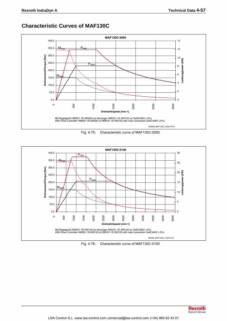
Rexroth IndraDyn A Technical Data 4-57
Characteristic Curves of MAF130C
��)�&�%�����
�+�
$�+�
���+�
�$�+�
)��+�
)$�+�
���+�
�$�+�
%��+�
�
$��
����
�$��
)���
)$��
����
��� ��������������
�����������������
�
)
%
�
-
��
�)
�%
������ ���!
��"#
�
���
�����
&��
&����
����./�0����8���$������
���3��4��5���������/(��$%��6��7������6�����/(��)���� 08%��69/$�:(��"1����8�����44����������/(��$%����6�����/(��)�;��"����<����<����� 08%��69/$�:
Fig. 4-75: Characteristic curve of MAF130C-0050
��)�&�%�����
�+�
$�+�
���+�
�$�+�
)��+�
)$�+�
���+�
�$�+�
%��+�
�
$��
����
�$��
)���
)$��
����
�$��
%���
%$��
$���
$$��
����
��� ��������������
�����������������
�
$
��
�$
)�
)$
��
������ ���!
��"#
�
���
�����
&��
&����
����./�0����8����������
���3��4��5���������/(��$���6��7������6�����/(��)���� 08%��69/$�:(��"1����8�����44����������/(��$�����6�����/(��)�;��"����<����<����� 08%��69/$�:
Fig. 4-76: Characteristic curve of MAF130C-0100
LSA Control S.L. www.lsa-control.com [email protected] (+34) 960 62 43 01

4-58 Technical Data Rexroth IndraDyn A
��)�&�%�����
�+�
$�+�
���+�
�$�+�
)��+�
)$�+�
���+�
�$�+�
�
$��
����
�$��
)���
)$��
����
�$��
%���
%$��
$���
$$��
����
�$��
,���
,$��
��� ��������������
�����������������
�
$
��
�$
)�
)$
��
�$
%�
%$
$�
������ ���!
��"#
�
���
�����
&��
&����
����./�0����8���$������
���3��4��5���������/(��$���6��7������6�����/(��)���� 08%��69/$�:(��"1����8�����44����������/(��$�����6�����/(��)�;��"����<����<����� 08%��69/$�:
Fig. 4-77: Characteristic curve of MAF130C-0150
��)�&�%��$��
�+�
$�+�
���+�
�$�+�
)��+�
)$�+�
���+�
�$�+�
�
$��
����
�$��
)���
)$��
����
�$��
%���
%$��
$���
$$��
����
�$��
,���
,$��
��� ��������������
�����������������
�
��
)�
��
%�
$�
��
������ ���!
��"#
�
���
�����
&��
&����
����./�0����8��)�������
���3��4��5���������/(��$���6��7������6�����/(��)���� 08%��69/$�:(��"1����8�����44����������/(��$�����6�����/(��)�;��"����<����<����� 08%��69/$�:
Fig. 4-78: Characteristic curve of MAF130C-0200
LSA Control S.L. www.lsa-control.com [email protected] (+34) 960 62 43 01

Rexroth IndraDyn A Technical Data 4-59
��)�&�%��$��
�+�
$�+�
���+�
�$�+�
)��+�
)$�+�
���+�
�$�+�
�
$��
����
�$��
)���
)$��
����
�$��
%���
%$��
$���
$$��
����
�$��
,���
,$��
��� ��������������
�����������������
�
��
)�
��
%�
$�
��
,�
-�
������ ���!
��"#
�
���
�����
&��
&����
����./�0����8��)$������
���3��4��5���������/(�)����6��7������6�����/(��)���� 08%��69/$�:(��"1����8�����44����������/(�)������6�����/(��)�;��"����<����<����� 08%��69/$�:
Fig. 4-79: Characteristic curve of MAF130C-0250
LSA Control S.L. www.lsa-control.com [email protected] (+34) 960 62 43 01

4-60 Technical Data Rexroth IndraDyn A
4.18 Technical Data Sheet for MAF130D Description Symbol Unit MAF130D
Motor data 1)Winding 0050 0100 0150 0200 0250Rated torque Mnenn Nm 230 220 200 200 190Rated speed nnenn rpm 500 1000 1500 2000 2500Rated power Pnenn kW 12 23 31.4 41.9 49.7Rated current Inenn A 32.3 52 72.6 93.9 113Continuous torque at standstill Mn1 Nm - 230 220 210 200Derating speed n1 rpm - 500 1000 1500 2000Continuous current at standstill In1 A - 53.8 78 97.5 113.6Maximum speed Mmax Nm 506 506 484 461 432Torque constant at 20°C KM_nenn Nm/A 7.71 4.81 3.21 2.51 2.04Min. cross section of power cable 2) A mm² 6 10 25 25 35Number of pole pairs p 3Moment of inertia of rotor 3) Jrot kgm² 0.179Motor mass 3) m kg 145
- Standard nmax rpm 3000 6000 7500- coupling attachment nmax rpm 3000 5250- reinforced nmax rpm 3000 6000 7500
Maximumspeed withbearing...
- High-speed nmax rpm 3000 6000 9000 6) 10000 6)Thermal time constant Tth min 15Duty cycle time (S6-44%) TC min i.p.Noise level 4) pSchall dB(A) 70 (+3)Permissible ambient temperature Tum °C 0....+40Permissible storage and transporttemperature Tlager °C -20....+80
Insulation class according toDIN VDE 0530-1 F
International Protection class IP65
Liquid cooling 5)Power loss to be dissipated PV kW 3.3
Cooling agent inlet Tein °C +10....+40Cooling agenttemperature Permissible increase at PV ∆Tdiff K 10
without fast coupling ∆pdiff bar 0.7Decompressionat Qmin with fast coupling ∆pdiff bar 1.4Required flow of coolant at PV Qmin l/min 4.8max. system pressure pmax bar 3
Holding brake (optional) Electrically-clamped Electrically-releasedTransmittable torque M4 Nm 100 80Connection voltage UBr V DC 24 ± 10 %Rated current IBr A 1.5 1.6Moment of inertia JBr kgm² 0.002Max. permissible braking energy Wmax Ws 30000Disengagement time t2 ms 140 110Engagement time t1 ms 110 70Maximum speed of brake nBr_max rpm 8000 8000Mass of brake m kg 81) Values determined according to IEC 60034-1. Current and voltage specified as root-mean-square values.2) Rated for cable assemblies with current carrying capacity according to VDE0298-4 (1992) and installation type B2
according to EN 60204-1 (1993) at 40°C ambient temperature.3) Values without holding brake.4) in 1 m distance, with PWN = 4kHz5) Data refer to water as a cooling agent. If using other coolant, re-calculate the data.
Observe instructions on coolant inlet temperature in chapter 9.6) Value is without a holding brake. This value may be limited by a holding brake.
Fig. 4-80: Data Sheet MAF130D
LSA Control S.L. www.lsa-control.com [email protected] (+34) 960 62 43 01

Rexroth IndraDyn A Technical Data 4-61
Characteristic Curves of MAF130D
��)�&�������
�+�
���+�
)��+�
���+�
%��+�
$��+�
���+�
�
$��
����
�$��
)���
)$��
����
��� ��������������
�����������������
�
$
��
�$
)�
)$
������ ���!
��"#
�
���
�����
&��
&����
����./�0����1���$������
���3��4��5���������/(��,���6��7������6�����/(��)���� 08%��69/$�:(��"1����8�����44����������/(��,�����6�����/(��)�;��"����<����<����� 08%��69/$�:
Fig. 4-81: Characteristic curve of MAF130D-0050
��)�&�������
�+�
���+�
)��+�
���+�
%��+�
$��+�
���+�
�
$��
����
�$��
)���
)$��
����
�$��
%���
%$��
$���
$$��
����
��� ��������������
�����������������
�
$
��
�$
)�
)$
��
�$
%�
%$
������ ���!
��"#
�
���
�����
&��
&����
����./�0����1����������
���3��4��5���������/(��$���6��7������6�����/(��)���� 08%��69/$�:(��"1����8�����44����������/(��$�����6�����/(��)�;��"����<����<����� 08%��69/$�:
Fig. 4-82: Characteristic curve of MAF130D-0100
LSA Control S.L. www.lsa-control.com [email protected] (+34) 960 62 43 01

4-62 Technical Data Rexroth IndraDyn A
��)�&�������
�+�
���+�
)��+�
���+�
%��+�
$��+�
���+�
�
$��
����
�$��
)���
)$��
����
�$��
%���
%$��
$���
$$��
����
�$��
,���
,$��
��� ��������������
�����������������
�
��
)�
��
%�
$�
��
,�
������ ���!
��"#
�
���
�����
&��
&����
����./�0����1���$������
���3��4��5���������/(�)����6��7������6�����/(��)���� 08%��69/$�:(��"1����8�����44����������/(�)������6�����/(��)�;��"����<����<����� 08%��69/$�:
Fig. 4-83: Characteristic curve of MAF130D-0150
��)�&����$��
�+�
$�+�
���+�
�$�+�
)��+�
)$�+�
���+�
�$�+�
%��+�
%$�+�
$��+�
�
$��
����
�$��
)���
)$��
����
�$��
%���
%$��
$���
$$��
����
�$��
,���
,$��
��� ��������������
�����������������
�
��
)�
��
%�
$�
��
,�
-�
=�
������ ���!
��"#
�
���
�����
&��
&����
����./�0����1��)�������
���3��4��5���������/(�)����6��7������6�����/(��)���� 08%��69/$�:(��"1����8�����44����������/(�)������6�����/(��)�;��"����<����<����� 08%��69/$�:
Fig. 4-84: Characteristic curve of MAF130D-0200
LSA Control S.L. www.lsa-control.com [email protected] (+34) 960 62 43 01

Rexroth IndraDyn A Technical Data 4-63
��)�&����$��
�+�
$�+�
���+�
�$�+�
)��+�
)$�+�
���+�
�$�+�
%��+�
%$�+�
$��+�
�
$��
����
�$��
)���
)$��
����
�$��
%���
%$��
$���
$$��
����
�$��
,���
,$��
��� ��������������
�����������������
�
��
)�
��
%�
$�
��
,�
-�
=�
���
������ ���!
��"#
�
���
�����
&��
&����
����./�0����1��)$������
���3��4��5���������/(�)����6��7������6�����/(��)���� 08%��69/$�:(��"1����8�����44����������/(�)������6�����/(��)�;��"����<����<����� 08%��69/$�:
Fig. 4-85: Characteristic curve of MAF130D-0250
LSA Control S.L. www.lsa-control.com [email protected] (+34) 960 62 43 01

4-64 Technical Data Rexroth IndraDyn A
4.19 Technical Data Sheet for MAF160B Description Symbol Unit MAF160B
Motor data 1)Winding 0050 0100 0150 0200Rated torque Mnenn Nm 270 260 250 240Rated speed nnenn rpm 500 1000 1500 2000Rated power Pnenn kW 14.1 27.2 39.3 50.3Rated current Inenn A 37.9 73.7 89.5 108.5Continuous torque at standstill Mn1 Nm - 270 260 250Derating speed n1 rpm - 500 1000 1500Continuous current at standstill In1 A - 75.8 92.1 112.3Maximum speed Mmax Nm 594 593 571 550Torque constant at 20°C KM_nenn Nm/A 8.25 4.13 3.3 2.4Min. cross section of power cable 2) A mm² 6 25 25 35Number of pole pairs p 3Moment of inertia of rotor 3) Jrot kgm² 0.23Motor mass 3) m kg 195
- Standard nmax rpm 3000 6000- coupling attachment nmax rpm 3000 4200- reinforced nmax rpm 3000 6000
Maximumspeed withbearing...
- High-speed nmax rpm not availableThermal time constant Tth min 20Duty cycle time (S6-44%) TC min i.p.Noise level 4) pSchall dB(A) 72 (+3)Permissible ambient temperature Tum °C 0....+40Permissible storage and transporttemperature Tlager °C -20....+80
Insulation class according toDIN VDE 0530-1 F
International Protection class IP65
Liquid cooling 5)Power loss to be dissipated PV kW 2.7 4.0 4.5
Cooling agent inlet Tein °C +10....+40Cooling agenttemperature Permissible increase at PV ∆Tdiff K 10
without fast coupling ∆pdiff bar 0.4Decompressionat Qmin with fast coupling ∆pdiff bar 0.8Required flow of coolant at PV Qmin l/min 3.8 5.8 6.5max. system pressure pmax bar 3
Holding brake (optional) Electrically-clamped
Electrically-released
Electrically-released -reinforced
Transmittable torque M4 Nm 100 240Connection voltage UBr V DC 24 ± 10 %Rated current IBr A 1.8 2.0 1.87Moment of inertia JBr kgm² 0.0065 0.0188Max. permissible braking energy Wmax Ws 40000 70000Disengagement time t2 ms 100 190 300Engagement time t1 ms 85 12 30Mass m kg 20 251) Values determined according to IEC 60034-1. Current and voltage specified as root-mean-square values.2) Rated for cable assemblies with current carrying capacity according to VDE0298-4 (1992) and installation type B2
according to EN 60204-1 (1993) at 40°C ambient temperature.3) Values without holding brake.4) in 1 m distance, with PWN = 4kHz5) Data refer to water as a cooling agent. If using other coolant, re-calculate the data.
Observe instructions on coolant inlet temperature in chapter 9.
Fig. 4-86: Data Sheet MAF160B
LSA Control S.L. www.lsa-control.com [email protected] (+34) 960 62 43 01

Rexroth IndraDyn A Technical Data 4-65
Characteristic Curves of MAF160B
��)�'�������
�+�
���+�
)��+�
���+�
%��+�
$��+�
���+�
,��+�
�
$��
����
�$��
)���
)$��
����
��� ��������������
�����������������
�
$
��
�$
)�
)$
������ ���!
��"#
�
���
�����
&��
&����
����./�0����2���$������
���3��4��5���������/(��,���6��7������6�����/(��)���� 08%��69/$�:(��"1����8�����44����������/(��,�����6�����/(��)�;��"����<����<����� 08%��69/$�:
Fig. 4-87: Characteristic curve of MAF160B-0050
��)�'�������
�+�
���+�
)��+�
���+�
%��+�
$��+�
���+�
,��+�
�
$��
����
�$��
)���
)$��
����
�$��
%���
%$��
$���
$$��
����
��� ��������������
�����������������
�
��
)�
��
%�
$�
��
������ ���!��"#
�
���
�����
&��
&����
����./�0����2����������
���3��4��5���������/(��$���6��7������6�����/(��)���� 08%��69/$�:(��"1����8�����44����������/(��$�����6�����/(��)�;��"����<����<����� 08%��69/$�:
Fig. 4-88: Characteristic curve of MAF160B-0100
LSA Control S.L. www.lsa-control.com [email protected] (+34) 960 62 43 01

4-66 Technical Data Rexroth IndraDyn A
��)�'�������
�+�
���+�
)��+�
���+�
%��+�
$��+�
���+�
,��+�
�
$��
����
�$��
)���
)$��
����
�$��
%���
%$��
$���
$$��
����
��� ��������������
�����������������
�
��
)�
��
%�
$�
��
,�
-�
������ ���!��"#
�
���
�����
&��
&����
����./�0����2���$������
���3��4��5���������/(�)����6��7������6�����/(��)���� 08%��69/$�:(��"1����8�����44����������/(�)������6�����/(��)�;��"����<����<����� 08%��69/$�:
Fig. 4-89: Characteristic curve of MAF160B-0150
��)�'����$��
�+�
���+�
)��+�
���+�
%��+�
$��+�
���+�
�
$��
����
�$��
)���
)$��
����
�$��
%���
%$��
$���
$$��
����
��� ��������������
�����������������
�
��
)�
��
%�
$�
��
,�
-�
=�
���
������ ���!
��"#
�
���
�����
&��
&����
����./�0����2��)�������
���3��4��5���������/(�)����6��7������6�����/(��)���� 08%��69/$�:(��"1����8�����44����������/(�)������6�����/(��)�;��"����<����<����� 08%��69/$�:
Fig. 4-90: Characteristic curve of MAF160B-0200
LSA Control S.L. www.lsa-control.com [email protected] (+34) 960 62 43 01

Rexroth IndraDyn A Technical Data 4-67
4.20 Technical Data Sheet for MAF160C Description Symbol Unit MAF160C
Motor data 1)Winding 0050 0100 0150 0200Rated torque Mnenn Nm 340 325 300 285Rated speed nnenn rpm 500 1000 1500 2000Rated power Pnenn kW 17.8 34 47.1 59.7Rated current Inenn A 47.4 91.2 109.5 136Continuous torque at standstill Mn1 Nm - 340 310 295Derating speed n1 rpm - 500 1000 1500Continuous current at standstill In1 A - 94.8 111.9 141.4Maximum speed Mmax Nm 748 746 681 658Torque constant at 20°C KM_nenn Nm/A 7.76 3.88 3.37 2.3Min. cross section of power cable 2) A mm² 10 25 35 2x16Number of pole pairs p 3Moment of inertia of rotor 3) Jrot kgm² 0.311Motor mass 3) m kg 233
- Standard nmax rpm 3000 6000- coupling attachment nmax rpm 3000 4200- reinforced nmax rpm 3000 6000
Maximumspeed withbearing...
- High-speed nmax rpm not availableThermal time constant Tth min 20Duty cycle time (S6-44%) TC min i.p.Noise level 4) pSchall dB(A) 72 (+3)Permissible ambient temperature Tum °C 0....+40Permissible storage and transport temperature Tlager °C -20....+80Insulation class according to DIN VDE 0530-1 FInternational Protection class IP65
Liquid cooling 5)Power loss to be dissipated PV kW 4.5 3.8 4.2
Cooling agent inlet Tein °C +10....+40Cooling agenttemperature Permissible increase at PV ∆Tdiff K 10
without fast coupling ∆pdiff bar 0.6Decompressionat Qmin with fast coupling ∆pdiff bar 1.2Required flow of coolant at PV Qmin l/min 6.5 5.5 6max. system pressure pmax bar 3
Holding brake (optional) Electrically-clamped
Electrically-released
Electrically-released -reinforced
Transmittable torque M4 Nm 100 240Connection voltage UBr V DC 24 ± 10 %Rated current IBr A 1.8 2.0 1.87Moment of inertia JBr kgm² 0.0065 0.0188Max. permissible braking energy Wmax Ws 40000 70000Disengagement time t2 ms 100 190 300Engagement time t1 ms 85 12 30Mass m kg 20 251) Values determined according to IEC 60034-1. Current and voltage specified as root-mean-square values.2) Rated for cable assemblies with current carrying capacity according to VDE0298-4 (1992) and installation type B2
according to EN 60204-1 (1993) at 40°C ambient temperature.3) Values without holding brake.4) in 1 m distance, with PWN = 4kHz5) Data refer to water as a cooling agent. If using other coolant, re-calculate the data.
Observe instructions on coolant inlet temperature in chapter 9.
Fig. 4-91: Data Sheet MAF160C
LSA Control S.L. www.lsa-control.com [email protected] (+34) 960 62 43 01

4-68 Technical Data Rexroth IndraDyn A
Characteristic Curves of MAF160C
��)�'�%�����
�+�
���+�
)��+�
���+�
%��+�
$��+�
���+�
,��+�
-��+�
�
$��
����
�$��
)���
)$��
����
��� ��������������
�����������������
�
$
��
�$
)�
)$
��
�$
������ ���!
��"#
�
���
�����
&��
&����
����./�0����8���$������
���3��4��5���������/(��$���6��7������6�����/(��)���� 08%��69/$�:(��"1����8�����44����������/(��$�����6�����/(��)�;��"����<����<����� 08%��69/$�:
Fig. 4-92: Characteristic curve of MAF160C-0050
��)�'�%�����
�+�
���+�
)��+�
���+�
%��+�
$��+�
���+�
,��+�
-��+�
�
$��
����
�$��
)���
)$��
����
�$��
%���
%$��
$���
$$��
����
��� ��������������
�����������������
�
��
)�
��
%�
$�
��
,�
������ ���!
��"#
�
���
�����
&��
&����
����./�0����8����������
���3��4��5���������/(�)����6��7������6�����/(��)���� 08%��69/$�:(��"1����8�����44����������/(�)������6�����/(��)�;��"����<����<����� 08%��69/$�:
Fig. 4-93: Characteristic curve of MAF160C-0100
LSA Control S.L. www.lsa-control.com [email protected] (+34) 960 62 43 01

Rexroth IndraDyn A Technical Data 4-69
��)�'�%�����
�+�
���+�
)��+�
���+�
%��+�
$��+�
���+�
,��+�
-��+�
�
$��
����
�$��
)���
)$��
����
�$��
%���
%$��
$���
$$��
����
��� ��������������
�����������������
�
��
)�
��
%�
$�
��
,�
-�
=�
���
������ ���!
��"#
�
���
�����
&��
&����
����./�0����8���$������
���3��4��5���������/(�)����6��7������6�����/(��)���� 08%��69/$�:(��"1����8�����44����������/(�)������6�����/(��)�;��"����<����<����� 08%��69/$�:
Fig. 4-94: Characteristic curve of MAF160C-0150
��)�'�%��$��
�+�
���+�
)��+�
���+�
%��+�
$��+�
���+�
�
$��
����
�$��
)���
)$��
����
�$��
%���
%$��
$���
$$��
����
��� ��������������
�����������������
�
��
)�
��
%�
$�
��
,�
-�
=�
���
������ ���!
��"#
�
���
�����
&��
&����
����./�0����8��)�������
���3��4��5���������/(�)����6��7������6�����/(��)���� 08%��69/$�:(��"1����8�����44����������/(�)������6�����/(��)�;��"����<����<����� 08%��69/$�:
Fig. 4-95: Characteristic curve of MAF160C-0200
LSA Control S.L. www.lsa-control.com [email protected] (+34) 960 62 43 01

4-70 Technical Data Rexroth IndraDyn A
4.21 Technical Data Sheet for MAF180C Description Symbol Unit MAF180C
Motor data 1)Winding 0050 0100 0150 0200Rated torque Mnenn Nm 435 390 365 318Rated speed nnenn rpm 500 1000 1500 2000Rated power Pnenn kW 22.8 40.8 57.3 66.6Rated current Inenn A 49.8 90.7 128.8 154Continuous torque at standstill Mn1 Nm - 435 390 336Derating speed n1 rpm - 500 1000 1500Continuous current at standstill In1 A - 99.7 136.1 160.5Maximum speed Mmax Nm 986 957 858 739Torque constant at 20°C KM_nenn Nm/A 9.61 4.67 3.11 2.39Min. cross section of power cable 2) A mm² 10 25 2x16 2x25Number of pole pairs p 3Moment of inertia of rotor 3) Jrot kgm² 0.49Motor mass 3) m kg 312
- Standard nmax rpm 3000 6000- coupling attachment nmax rpm 3000 4200- reinforced nmax rpm 3000 6000
Maximumspeed withbearing...
- High-speed nmax rpm not availableThermal time constant Tth min 25Duty cycle time (S6-44%) TC min i.p.Noise level 4) pSchall dB(A) 75 (+3)Permissible ambient temperature Tum °C 0....+40Permissible storage and transporttemperature Tlager °C -20....+80
Insulation class according toDIN VDE 0530-1 F
International Protection class IP65
Liquid cooling 5)Power loss to be dissipated PV kW 4.5
Cooling agent inlet Tein °C +10....+40Cooling agenttemperature Permissible increase at PV ∆Tdiff K 10
without fast coupling ∆pdiff bar 0.6Decompressionat Qmin with fast coupling ∆pdiff bar 1.2Required flow of coolant at PV Qmin l/min 6.6max. system pressure pmax bar 3
Holding brake (optional) Electrically-clamped Electrically-releasedTransmittable torque M4 Nm 300 240Connection voltage UBr V DC 24 ± 10 %Rated current IBr A 2 1.87Moment of inertia JBr kgm² 0.0188Max. permissible braking energy Wmax Ws 70000Disengagement time t2 ms 90 300Engagement time t1 ms 150 30Mass of brake m kg 251) Values determined according to IEC 60034-1. Current and voltage specified as root-mean-square values.2) Rated for cable assemblies with current carrying capacity according to VDE0298-4 (1992) and installation type B2
according to EN 60204-1 (1993) at 40°C ambient temperature.3) Values without holding brake.4) in 1 m distance, with PWN = 4kHz5) Data refer to water as a cooling agent. If using other coolant, re-calculate the data.
Observe instructions on coolant inlet temperature in chapter 9.
Fig. 4-96: Data Sheet MAF180C
LSA Control S.L. www.lsa-control.com [email protected] (+34) 960 62 43 01

Rexroth IndraDyn A Technical Data 4-71
Characteristic Curves of MAF180C
��)�(�%�����
�+�
)��+�
%��+�
���+�
-��+�
����+�
�)��+�
�
$��
����
�$��
)���
)$��
����
��� ��������������
�����������������
�
$
��
�$
)�
)$
��
�$
%�
%$
������ ���!
��"#
�
���
�����
&��
&����
����./�0��-�8���$������
���3��4��5���������/(��$���6��7������6�����/(��)���� 08%��69/$�:(��"1����8�����44����������/(��$�����6�����/(��)�;��"����<����<����� 08%��69/$�:
Fig. 4-97: Characteristic curve of MAF180C-0050
��)�(�%�����
�+�
)��+�
%��+�
���+�
-��+�
����+�
�)��+�
�
$��
����
�$��
)���
)$��
����
�$��
%���
%$��
$���
$$��
����
��� ��������������
�����������������
�
��
)�
��
%�
$�
��
,�
-�
=�
���
������ ���!��"#
�
���
�����
&��
&����
����./�0��-�8����������
���3��4��5���������/(�)����6��7������6�����/(��)���� 08%��69/$�:(��"1����8�����44����������/(�)������6�����/(��)�;��"����<����<����� 08%��69/$�:
Fig. 4-98: Characteristic curve of MAF180C-0100
LSA Control S.L. www.lsa-control.com [email protected] (+34) 960 62 43 01

4-72 Technical Data Rexroth IndraDyn A
��)�(�%�����
�+�
���+�
)��+�
���+�
%��+�
$��+�
���+�
,��+�
�
$��
����
�$��
)���
)$��
����
�$��
%���
%$��
$���
$$��
����
��� ��������������
�����������������
�
��
)�
��
%�
$�
��
,�
-�
=�
���
������ ���!
��"#
�
���
�����
&��
&����
����./�0��-�8���$������
���3��4��5���������/(�)����6��7������6�����/(��)���� 08%��69/$�:(��"1����8�����44����������/(�)������6�����/(��)�;��"����<����<����� 08%��69/$�:
Fig. 4-99: Characteristic curve of MAF180C-0150
��)�(�%��$��
�+�
$�+�
���+�
�$�+�
)��+�
)$�+�
���+�
�$�+�
%��+�
%$�+�
$��+�
�
$��
����
�$��
)���
)$��
����
�$��
%���
%$��
$���
$$��
����
��� ��������������
�����������������
�
��
)�
��
%�
$�
��
,�
-�
=�
���
������ ���!
��"#
�
���
�����
&��
&����
����./�0��-�8��)�������
���3��4��5�1�3�%��/(%����� 08%�����%-�69/$�:(��"1����8�����44��1�3�%��/(%��;��"����<����<����� 08%������%-�69/$�:
Fig. 4-100: Characteristic curve of MAF180C-0200
LSA Control S.L. www.lsa-control.com [email protected] (+34) 960 62 43 01

Rexroth IndraDyn A Technical Data 4-73
4.22 Technical Data Sheet for MAF180D
Description Symbol Unit MAF180D
Motor data 1)Winding 0050 0100 0150 0200Rated torque Mnenn Nm 500 460 435 400Rated speed nnenn rpm 500 1000 1500 2000Rated power Pnenn kW 26.1 48.1 68.3 83.8Rated current Inenn A 60.4 94.8 135.5 168.5Continuous torque at standstill Mn1 Nm - 500 460 460Derating speed n1 rpm - 500 1000 1500Continuous current at standstill In1 A - 101.9 142.1 187.3Maximum speed Mmax Nm 1100 1094 1013 1008Torque constant at 20°C KM_nenn Nm/A 10 5.23 3.49 2.75Min. cross section of power cable 2) A mm² 16 35 2x16 2x25Number of pole pairs p 3Moment of inertia of rotor 3) Jrot kgm² 0.855Motor mass 3) m kg 381
- Standard nmax rpm 3000 6000- coupling attachment nmax rpm 3000 4200- reinforced nmax rpm 3000 6000
Maximumspeed withbearing...
- High-speed nmax rpm not availableThermal time constant Tth min 25Duty cycle time (S6-44%) TC min i.p.Noise level 4) pSchall dB(A) 75 (+3)Permissible ambient temperature Tum °C 0....+40Permissible storage and transporttemperature Tlager °C -20....+80
Insulation class according toDIN VDE 0530-1 F
International Protection class IP65
Liquid cooling 5)Power loss to be dissipated PV kW 3.5 2.5
Cooling agent inlet Tein °C +10....+40Cooling agenttemperature Permissible increase at PV ∆Tdiff K 10
without fast coupling ∆pdiff bar 0.6Decompressionat Qmin with fast coupling ∆pdiff bar 1.2Required flow of coolant at PV Qmin l/min 5.1 3.6max. system pressure pmax bar 3
Holding brake (optional) Electrically-clamped Electrically-releasedTransmittable torque M4 Nm 300 240Connection voltage UBr V DC 24 ± 10 %Rated current IBr A 2 1.87Moment of inertia JBr kgm² 0.0188Max. permissible braking energy Wmax Ws 70000Disengagement time t2 ms 90 300Engagement time t1 ms 150 30Mass of brake m kg 251) Values determined according to IEC 60034-1. Current and voltage specified as root-mean-square values.2) Rated for cable assemblies with current carrying capacity according to VDE0298-4 (1992) and installation type B2
according to EN 60204-1 (1993) at 40°C ambient temperature.3) Values without holding brake.4) in 1 m distance, with PWN = 4kHz5) Data refer to water as a cooling agent. If using other coolant, re-calculate the data.
Observe instructions on coolant inlet temperature in chapter 9.
Fig. 4-101: Data Sheet MAF180D
LSA Control S.L. www.lsa-control.com [email protected] (+34) 960 62 43 01

4-74 Technical Data Rexroth IndraDyn A
Characteristic Curves of MAF180D
��)�(�������
�+�
)��+�
%��+�
���+�
-��+�
����+�
�)��+�
�
$��
����
�$��
)���
)$��
����
��� ��������������
�����������������
�
$
��
�$
)�
)$
��
�$
%�
%$
$�
������ ���!
��"#
�
���
�����
&��
&����
����./�0��-�1���$������
���3��4��5���������/(��$���6��7������6�����/(��)���� 08%��69/$�:(��"1����8�����44����������/(��$�����6�����/(��)�;��"����<����<����� 08%��69/$�:
Fig. 4-102: Characteristic curve of MAF180D-0050
��)�(�������
�+�
)��+�
%��+�
���+�
-��+�
����+�
�)��+�
�
$��
����
�$��
)���
)$��
����
�$��
%���
%$��
$���
$$��
����
��� ��������������
�����������������
�
)�
%�
��
-�
���
�)�
������ ���!
��"#
�
���
�����
&��
&����
����./�0��-�1����������
���3��4��5���������/(�)����6��7������6�����/(��)���� 08%��69/$�:(��"1����8�����44����������/(�)������6�����/(��)�;��"����<����<����� 08%��69/$�:
Fig. 4-103: Characteristic curve of MAF180D-0100
LSA Control S.L. www.lsa-control.com [email protected] (+34) 960 62 43 01

Rexroth IndraDyn A Technical Data 4-75
�����������
�
�
�
�
�
�
��
�
�
��
�
��
�
��
�
��� ��������������������
���������������������
�
�
�
�
��
��
����������� �����!"
����./�0��-�1���$������
���3��4��5�1�3$�)/($��A��� 08%������%-�69/$�:(��"1����8�����44��1�3$�)/($��A;��"����<����<����� 08%������%-�69/$�:
Fig. 4-104: Characteristic curve of MAF180D-0150
���������#��
�
�
�
�
�
�
��
�
�
��
�
��
�
��
�
��� ��������������������
���������������������
�
�
�
�
��
��
�
����������� �����!"
����./�0��-�1��)�������
���3��4��5�1�3�$�)/(,��A��� 08%�����%-�69/$�:(��"1����8�����44��1�3�$�)/(,��A;��"����<����<����� 08%������%-�69/$�:
Fig. 4-105: Characteristic curve of MAF180D-0200
LSA Control S.L. www.lsa-control.com [email protected] (+34) 960 62 43 01

4-76 Technical Data Rexroth IndraDyn A
LSA Control S.L. www.lsa-control.com [email protected] (+34) 960 62 43 01

Rexroth IndraDyn A Dimension Sheets 5-1
5 Dimension Sheets
5.1 Dimension Sheet for MAD100, without Brake
106-0425-3001-01.tif
Fig. 5-1: Dimension sheet for MAD100, without brake
LSA Control S.L. www.lsa-control.com [email protected] (+34) 960 62 43 01

5-2 Dimension Sheets Rexroth IndraDyn A
5.2 Dimension Sheet for MAD100, with Brakes 1 and 5
106-0456-3001-00.tif
Fig. 5-2: Dimension sheet for MAD100, with brakes 1 and 5
LSA Control S.L. www.lsa-control.com [email protected] (+34) 960 62 43 01

Rexroth IndraDyn A Dimension Sheets 5-3
5.3 Dimension Sheet for MAD130, without Brake
106-0403-3001-01.tif
Fig. 5-3: Dimension sheet for MAD130, without brake
LSA Control S.L. www.lsa-control.com [email protected] (+34) 960 62 43 01

5-4 Dimension Sheets Rexroth IndraDyn A
5.4 Dimension Sheet for MAD130, with Brakes 1 and 5
106-0404-3001-01.tif
Fig. 5-4: Dimension sheet for MAD130, with brakes 1 and 5
LSA Control S.L. www.lsa-control.com [email protected] (+34) 960 62 43 01

Rexroth IndraDyn A Dimension Sheets 5-5
5.5 Dimension Sheet for MAD160, without Brake
106-0413-3001-02.tif
Fig. 5-5: Dimension sheet for MAD160, without brake
LSA Control S.L. www.lsa-control.com [email protected] (+34) 960 62 43 01

5-6 Dimension Sheets Rexroth IndraDyn A
5.6 Dimension Sheet for MAD160, with Brakes 1 and 5
106-0414-3001-01.tif
Fig. 5-6: Dimension sheet for MAD160, with brakes 1 and 5
LSA Control S.L. www.lsa-control.com [email protected] (+34) 960 62 43 01

Rexroth IndraDyn A Dimension Sheets 5-7
5.7 Dimension Sheet for MAD160, with Brake 3
106-0415-3001-01.tif
Fig. 5-7: Dimension sheet for MAD160, with brake 3
LSA Control S.L. www.lsa-control.com [email protected] (+34) 960 62 43 01
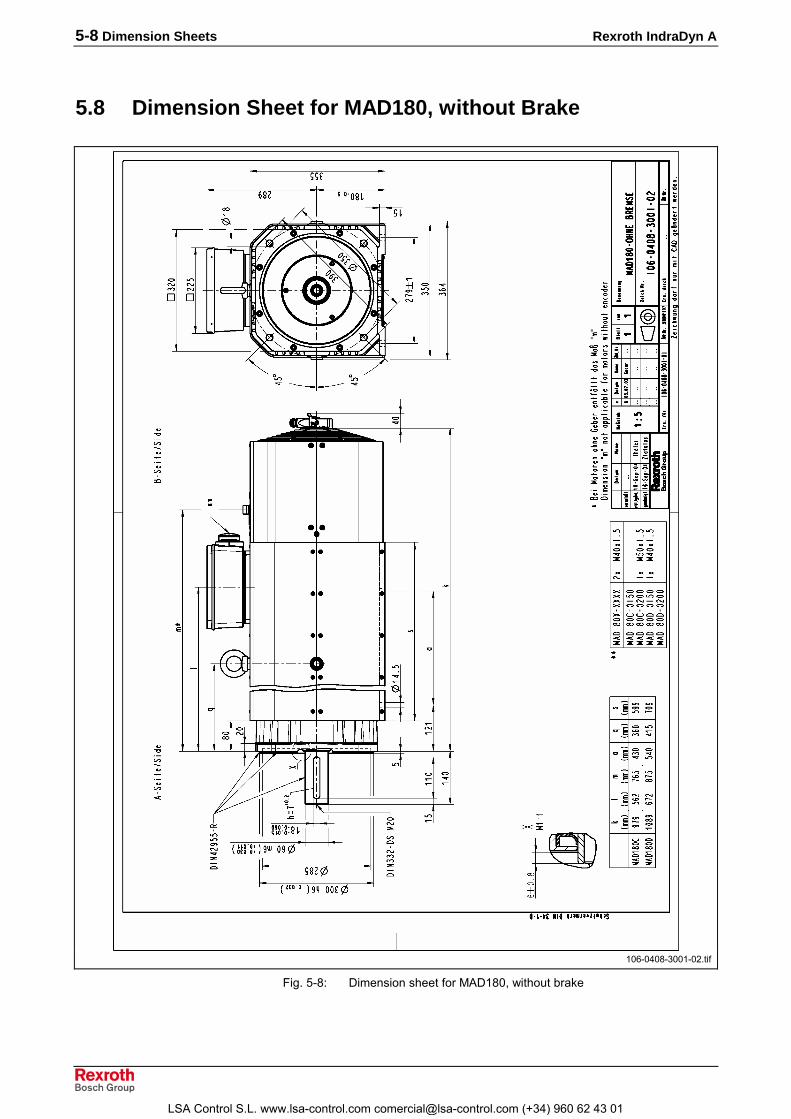
5-8 Dimension Sheets Rexroth IndraDyn A
5.8 Dimension Sheet for MAD180, without Brake
106-0408-3001-02.tif
Fig. 5-8: Dimension sheet for MAD180, without brake
LSA Control S.L. www.lsa-control.com [email protected] (+34) 960 62 43 01

Rexroth IndraDyn A Dimension Sheets 5-9
5.9 Dimension Sheet for MAD180, with Brakes 2 and 5
106-0409-3001-01.tif
Fig. 5-9: Dimension sheet for MAD180, with brakes 2 and 5
LSA Control S.L. www.lsa-control.com [email protected] (+34) 960 62 43 01

5-10 Dimension Sheets Rexroth IndraDyn A
5.10 Dimension Sheet for MAF100, without Brake
106-0440-3001-01.tif
Fig. 5-10: Dimension sheet for MAF100, without brake
LSA Control S.L. www.lsa-control.com [email protected] (+34) 960 62 43 01

Rexroth IndraDyn A Dimension Sheets 5-11
5.11 Dimension Sheet for MAF100, with Brakes 1 and 5
106-0461-3001-00.tif
Fig. 5-11: Dimension sheet for MAF100, with brakes 1 and 5
LSA Control S.L. www.lsa-control.com [email protected] (+34) 960 62 43 01

5-12 Dimension Sheets Rexroth IndraDyn A
5.12 Dimension Sheet for MAF130, without Brake
106-0406-3001-01.tif
Fig. 5-12: Dimension sheet for MAF130, without brake
LSA Control S.L. www.lsa-control.com [email protected] (+34) 960 62 43 01

Rexroth IndraDyn A Dimension Sheets 5-13
5.13 Dimension Sheet for MAF130, with Brakes 1 and 5
106-0407-3001-01.tif
Fig. 5-13: Dimension sheet for MAF130, with brakes 1 and 5
LSA Control S.L. www.lsa-control.com [email protected] (+34) 960 62 43 01

5-14 Dimension Sheets Rexroth IndraDyn A
5.14 Dimension Sheet for MAF160, without Brake
106-0416-3001-03.tif
Fig. 5-14: Dimension sheet for MAF160, without brake
LSA Control S.L. www.lsa-control.com [email protected] (+34) 960 62 43 01

Rexroth IndraDyn A Dimension Sheets 5-15
5.15 Dimension Sheet for MAF160, with Brakes 1 and 5
106-0417-3001-02.tif
Fig. 5-15: Dimension sheet for MAF160, with brakes 1 and 5
LSA Control S.L. www.lsa-control.com [email protected] (+34) 960 62 43 01

5-16 Dimension Sheets Rexroth IndraDyn A
5.16 Dimension Sheet for MAF160, with Brake 3
106-0418-3001-02.tif
Fig. 5-16: Dimension sheet for MAF160, with brake 3
LSA Control S.L. www.lsa-control.com [email protected] (+34) 960 62 43 01

Rexroth IndraDyn A Dimension Sheets 5-17
5.17 Dimension Sheet for MAF180, without Brake
106-0410-3001-02.tif
Fig. 5-17: Dimension sheet for MAF180, without brake
LSA Control S.L. www.lsa-control.com [email protected] (+34) 960 62 43 01

5-18 Dimension Sheets Rexroth IndraDyn A
5.18 Dimension Sheet for MAF180, with Brakes 2 and 5
106-0411-3001-01.tif
Fig. 5-18: Dimension sheet for MAF180, with brakes 2 and 5
LSA Control S.L. www.lsa-control.com [email protected] (+34) 960 62 43 01

Rexroth IndraDyn A Type Codes 6-1
6 Type Codes
6.1 IntroductionIndraDyn A is the general product name for Bosch Rexroth's housedasynchronous motors.The type code describes the available motor variants; it is the basis forselecting and ordering products from Bosch Rexroth. This applies to bothnew products as well as spare parts and repairs.The following description gives an overview of the individual positions ofthe type code and their meanings.
Note: When selecting a product, always consider the detailedspecifications in Chapter 4 �Technical Data� and Chapter 9�Application Notes�.
Definition
1. ProductMAD is the description of the blower cooled, housed asynchronousmotors.MAF is the description of liquid-cooled, housed asynchronous motors.
2. Motor Frame SizeThe motor frame size is derived from the dimensions of the output flangeand represents different power ranges.
3. Motor Frame LengthWithin a series, the graduation of increasing motor frame length isindicated by ID letters in alphabetic order.Frame lengths are, for example, B, C and D.
4. Winding CodeThe four-digit sequence of figures identifies the rated speed applicable forthe respective type of winding. The last figure is omitted. Example:Winding ID 0200 stands for a rated speed of 2000 rpm.
5. Type of CoolingMAD motors must always be operated with a fan whose air currents areguided from the air guide plates over the surface of the motor ("surfaceventilation"). The air current is defined as "blowing" according to thefollowing figure.
Abbrev. Columns 1 2 3
Abbrev. Columns 4 5 6
Abbrev. Column 7
Abbrev. Columns 9 10 11 12
Abbrev. Columns 14 15
LSA Control S.L. www.lsa-control.com [email protected] (+34) 960 62 43 01

6-2 Type Codes Rexroth IndraDyn A
�B)
� ��4
C4�7�� ��.DE��������������� �� ���������
MAD_Definition6.EPS
Fig. 6-1: MAD, blowing fan
The fan unit can be removed for maintenance. Operation withoutventilation is not permissible.
MAF motors must always be operated with an external cooling system(not included in the delivery).
6. Motor EncoderIndraDyn A motors can be supplied with integrated encoders.
Option Type Periods Signal 1) InterfaceC0 Incremental encoder 2048 1 Vpp -
M0 Multiturn absolute encoder 512 1 Vpp I²C
M2 Multiturn absolute encoder 2048 1 Vpp EnDat2.1
N0 The motor is supplied without a factory-attached encoder unit. Therear of the motor is blocked by a cover.
S0 Singleturn absolute encoder 512 1 Vpp I²C
S2 Singleturn absolute encoder 2048 1 Vpp EnDat2.1
1) All encoder signals are sinusoidal.
Fig. 6-2: IndraDyn A motor encoders
7. Electrical ConnectionElectrical connection is made through a flanged socket-outlet or aterminal box.For more detailed information, see Chapter 8, �Connection Techniques�.
8. Output ShaftIn order to connect the machine elements to be driven to the motorshafts, the following options are available for all IndraDyn A motors:
Output Shaftwith keyway
smoothshaft whole-key
balancedhalf-key
balanced
Without shaft seal H Q L
With shaft seal G P K
Fig. 6-3: Output shaft options
Abbrev. Columns 17 18
Abbrev. Column 20
Abbrev. Column 21
LSA Control S.L. www.lsa-control.com [email protected] (+34) 960 62 43 01

Rexroth IndraDyn A Type Codes 6-3
Motors ordered with a keyway are always supplied with a key .Centering holes with a "DS" thread according to DIN 332, Sheet 2 arelocated on all motor output shafts. Details are contained in the respectivemotor dimension sheets.See the sections regarding the shaft seal and the output shaft in Chapter9, �Application Notes�.
9. Holding BrakeMAD100-180 and MAF100-160 can be supplied with integrated holdingbrakes with different holding torques. Depending on the application, an"electrically-clamping" or "electrically-releasing" holding brake can beselected.
Note: The motor holding brake is not suitable for protection ofpersonnel or as a service brake! Heed the notes regardingholding brakes in Chapter 9, "Application Notes" and Chapter12.1, "Commissioning ".
10. Frame ShapeIndraDyn A motors are supplied in the frame shape 05 (flange mounting)or frame shape 35 (flange and foot installation). The permitted conditionsof installation are explained in Chapter 9, "Application Notes".
11. BearingsThe standard bearing (option "N") consists of deep-groove ball bearingsin all IndraDyn A motors.Reinforced bearings (option "V") can be used in order to bear greaterradial forces. With reinforced bearing, there is an additional cylindrical-roller bearing at the drive side next to the deep-groove ball bearing.High-speed bearings (option �H�) consists of a deep-groove ball bearingand permits higher speeds at a reduced axial and radial load-bearingcapacity.The bearing for the coupling attachment (option �R�) consists of a deep-groove ball bearing. This type of bearing has a special bearing seat toabsorb rotary radial forces that may occur in motor operation with acoupling.Heed the notes regarding holding brakes in Chapter 4, �Technical Data�.� and Chapter 9, "Application Notes".
12. Vibration Severity ClassIndraDyn A motors are dynamically balanced according to therequirements of DIN ISO 2373; the standard is class "R". With framesizes MAD/MAF100-180, options ”S” and ”S1” can be selected.
Abbrev. Column 22
Abbrev. Columns 24 25
Abbrev. Column 27
Abbrev. Column 28
LSA Control S.L. www.lsa-control.com [email protected] (+34) 960 62 43 01

6-4 Type Codes Rexroth IndraDyn A
6.2 Type Code for MAD100
�* +���,���� �01 ������� F�01
$* -��)�� ��� �������������� F���
&* �� ����� .���"7 ������������ F2+8+1
.* #����� %�� �01���2F��$�+����+��$�+�)��+�)$�%�) �01���8F��$�+����+��$�+�)��+�)$�%�� �01���1F��$�+����+��$�+�)��+�)$�
�* %����� $�� 0 ��4E��+C4�;�� ��������������������� F�0
'* /�,����� ���4��@���C7�4@����<� ��;��"$�)��<������7 F����) ���4��@���C7�4@����<� ��+��1��)��+;��"
)�%-��<������7 �������������������������� F�)��� �@4���@���C7�4@����<� ��;��"$�)��<������7 F����% �@4���@���C7�4@����<� ��+�� 1��)��+;��"
)�%-��<������7 ��������������������������� F�)��$ G�<�������4��<� ��;��")�%-��<������7 ������ F8���� ;��"�@��������<� �� ���������������������� F��
0* /�,��, ��,���,����,�� 8����<���+0/7� � ������������������������������� F0,�) 8����<���+2/7� � ������������������������������� F2,�� 8����<���+��"� �������������������������������� F3,�% 8����<���+4�E� ��������������������������������� F.,�$ !������4C� <����<����+0/7� � �������������������� F�,�� !������4C� <����<����+2/7� � �������������������� F�
(* -� 1�;��"'�H
�4��� C�4��<� ;��" C�4��<� ;��" 7"�E� ������'�H "�4E'�H
-�� ;��"�@�7"�E�7��4����� � � .-�) ;��"7"�E�7��4����� I & �
� ) � % � , - =��$ � ) � % � , - =
)�$ � ) � % � , - =
��$ � ) � % � , - =
%�$
� ���4�B
�223*%�����
� 0 1 � � � 8 / � � � � / � 0 / � � / 2 � � / � $ / � �
�
$
$
RNC-41171-000_NOR_E_D0_2004-11-153.EPS
Fig. 6-4: Type code for MAD100 (1/2)
LSA Control S.L. www.lsa-control.com [email protected] (+34) 960 62 43 01

Rexroth IndraDyn A Type Codes 6-5
� ) � % � , - =��$ � ) � % � , - =
)�$ � ) � % � , - =
��$ � ) � % � , - =
%�$
� ���4�B
�223*%�����
� 0 1 � � � 8 / � � � � / � 0 / � � / 2 � � / � $ / � �
4* 5����� �2 "=�� ;��"�@�"�4 ��C��'� �������������������������������� F�=�) �4�<���<�44H/��4��7� +)%�� ��������������������������� F�=�� �4�<���<�44H/<4���� +���� ��������������������������� F$
��* ������� ���6����� �4�����@���� ���������������������������������������� F�$���) �4����� E�����@���� ��������������������������������� F�$
��* � �� ����� ���� �� ��������������������������������������������������� F����) ��"���� ������������������������������������������������� F����� E��<4@�<"��@���� ������������������������������������������� F3
�$* 7�2 ������3��6� ��)�� 3 ����������������������������������������������������������� F��)�) � ����������������������������������������������������������� F)�)�� �� ���������������������������������������������������������� F�
���8.��'��E���E�������� �����7"�E�97����<�@���:�4�<���<�4<����<����J�J�� J�J����@����7�H4�J�$J�7��4H����4�C4������2�����7J�J7��4H����4�C4�;��"4���"J2J�� J8J+7"�E�J�J�� "�4 ��C��'�J�J6�C������7������H�� �J��J�7��4H����4�C4�;��"4���"J2J�� J8J
&
$�
+�,����
&�7������E��;��<����<����F���
2/7� �
��"�
4�E�
0/7� �
&
.
.
RNC-41171-000_NOR_E_D0_2004-11-154.EPS
Fig. 6-5: Type code for MAD100 (2/2)
LSA Control S.L. www.lsa-control.com [email protected] (+34) 960 62 43 01

6-6 Type Codes Rexroth IndraDyn A
6.3 Type Code for MAD130
�* +���,���� �01 ������� F�01
$* -��)�� ��� �������������� F���
&* �� ����� .���"7 ������������ F2+8+1
.* #����� %�� �01���2F��$�+����+��$�+�)��+�)$�%�) �01���8F��$�+����+��$�+�)��+�)$�%�� �01���1F��$�+����+��$�+�)��+�)$�
�* %����� $�� 0 ��4E��+C4�;�� ��������������������� F�0
'* /�,����� ���4��@���C7�4@����<� ��;��"$�)��<������7 F����) ���4��@���C7�4@����<� ��+��1��)��+;��")�%-
��<������7 ������������������������������� F�)��� �@4���@���C7�4@����<� ��;��"$�)��<������7 F����% �@4���@���C7�4@����<� ��+��1��)��+;��")�%-
��<������7 ������������������������������� F�)��$ G�<�������4��<� ��;��")�%-��<������7 ������ F8���� ;��"�@��������<� �� ���������������������� F��
0* /�,��, ��,���,����,�� 8����<���+0/7� � ������������������������������� F0,�) 8����<���+2/7� � ������������������������������� F2,�� 8����<���+��"� �������������������������������� F3,�% 8����<���+4�E� ��������������������������������� F.,�$ !������4C� <����<����+0/7� � ������������������� F�,�� !������4C� <����<����+2/7� � ������������������� F�
(* -� 1�;��"'�H
�4��� C�4��<� ;��" C�4��<� ;��" 7"�E� ������'�H "�4E'�H
-�� ;��"�@�7"�E�7��4����� � � .-�) ;��"7"�E�7��4����� I & �
� ) � % � , - =��$ � ) � % � , - =
)�$ � ) � % � , - =
��$ � ) � % � , - =
%�$
� ���4�B
�223*%�����
� 0 1 � � � 2 / � � $ � / � 0 / � � / 0 I � / � $ / � �
�
$
$
RNC-41171-300_NOR_E_D0_2004-11-223.EPS
Fig. 6-6: Type code for MAD130 (1/2)
LSA Control S.L. www.lsa-control.com [email protected] (+34) 960 62 43 01

Rexroth IndraDyn A Type Codes 6-7
� ) � % � , - =��$ � ) � % � , - =
)�$ � ) � % � , - =
��$ � ) � % � , - =
%�$
� ���4�B
�223*%�����
� 0 1 � � � 2 / � � $ � / � 0 / � � / 0 I � / � $ / � �
4* 5����� �2 "=�� ;��"�@�"�4 ��C��'� �������������������������������� F�=�) �4�<���<�44H/��4��7� +-��� ��������������������������� F�=�� �4�<���<�44H/<4���� +����� �������������������������� F$
��* ������� ���6����� �4�����@���� ���������������������������������������� F�$���) �4����� E�����@���� ��������������������������������� F�$
��* � �� ����� ���� �� ��������������������������������������������������� F����) ��"���� ������������������������������������������������� F����� E��<4@�<"��@���� ������������������������������������������� F3���% ����E��<� C�����7 ������������������������������������������� F6
�$* 7�2 ������3��6� ��)�� 3 ����������������������������������������������������������� F��)�) � ����������������������������������������������������������� F)�)�� �� ���������������������������������������������������������� F�
���8.��'��E���E�������� �����7"�E�97����<�@���:�4�<���<�4<����<����J�J�� J�J����@����7�H4�J�$J�7��4H����4�C4������2�����7J�J�7��4H���4�C4�;��"4���"J2J�� J8J+7"�E�J�J�� "�4 ��C��'�J�J6�C������7������H�� �J�J�7��4H����4�C4�;��"4���"J2J�� J8J�� C�����7J�J+J�J�� J3J&
$
�
+�,����
&�7������E��;��<����<����F���
2/7� �
��"�
4�E�
0/7� �
&
.
.
RNC-41171-300_NOR_E_D0_2004-11-224.EPS
Fig. 6-7: Type code for MAD130 (2/2)
LSA Control S.L. www.lsa-control.com [email protected] (+34) 960 62 43 01

6-8 Type Codes Rexroth IndraDyn A
6.4 Type Code for MAD160
� ) � % � , - =��$ � ) � % � , - =
)�$ � ) � % � , - =
��$ � ) � % � , - =
%�$
� ���4�B
�223*%�����
� 0 1 � � � 2 / � � $ � / � 0 / 8 � / 0 � � / � $ / � �
�
$
$
�* +���,���� �01 ������� F�01
$* -��)�� ��� �������������� F���
&* �� ����� .���"7 �������������� F2+8
.* #����� �,��%�� �01���2 ��� F��$�+����+��$�+�)��%�) �01���8 ��� F��$�+����+��$�+�)��
�* %����� ����$�� 0 ��4E��+C4�;�� �������������������� F�0
'* /�,����� ���4��@���C7�4@����<� ��;��"$�)��<������7 F����) ���4��@���C7�4@����<� ��+��1��)��+;��")�%-
��<������7 ������������������������������� F�)��� �@4���@���C7�4@����<� ��;��"$�)��<������7 F����% �@4���@���C7�4@����<� ��+��1��)��+;��")�%-
��<������7 ������������������������������� F�)��$ G�<�������4��<� ��;��")�%-��<������7 ������ F8���� ;��"�@��������<� �� ���������������������� F��
0* /�,��, ��,���,����,�� 8����<���+0/7� � ������������������������������� F0,�) 8����<���+2/7� � ������������������������������� F2,�� 8����<���+��"� �������������������������������� F3,�% 8����<���+4�E� ���������������������������������� F.,�$ !������4C� <����<����+0/7� � ������������������� F�,�� !������4C� <����<����+2/7� � �������������������� F�
(* -� 1�;��"'�H
�4��� C�4��<� ;��" C�4��<� ;��" 7"�E� ������'�H "�4E'�H
-�� ;��"�@�7"�E�7��4����� � � .-�) ;��"7"�E�7��4����� I & �
RNC-41171-600_NOR_E_D0_2004-09-173.EPS
Fig. 6-8: Type code for MAD160 (1/2)
LSA Control S.L. www.lsa-control.com [email protected] (+34) 960 62 43 01

Rexroth IndraDyn A Type Codes 6-9
� ) � % � , - =��$ � ) � % � , - =
)�$ � ) � % � , - =
��$ � ) � % � , - =
%�$
� ���4�B
�223*%�����
� 0 1 � � � 2 / � � $ � / � 0 / 8 � / 0 � � / � $ / � �
4* 5����� �2 "=�� ;��"�@�"�4 ��C��'� �������������������������������� F�=�) �4�<���<�44H/��4��7� +����� �������������������������� F�=�� �4�<���<�44H/��4��7� +)%��� �������������������������� F�=�% �4�<���<�44H/<4���� +����� �������������������������� F$
��* ������� ���6����� �4�����@���� ���������������������������������������� F�$���) �4����� E�����@���� ��������������������������������� F�$
��* � �� ����� ���� �� ��������������������������������������������������� F����) ����E��<� C�����7 ������������������������������������������� F6���� E��<4@�<"��@���� ������������������������������������������� F3
�$* 7�2 ������3��6� ��)�� 3 ����������������������������������������������������������� F��)�) � ����������������������������������������������������������� F)�)�� �� ���������������������������������������������������������� F�
���8.��'��E���E�������� �����7"�E�97����<�@���:�4�<���<�4<����<����J�J�� J�J����@����7�H4�J�$J�7��4H����4�C4������6�C������7������H�� �J��J�7��4H����4�C4�;��"C�����7J�J&
$
�
+�,����
&�7������E��;��<����<����F���
2/7� �
��"�
4�E�
0/7� �
&
RNC-41171-600_NOR_E_D0_2004-09-174.EPS
Fig. 6-9: Type code for MAD160 (2/2)
LSA Control S.L. www.lsa-control.com [email protected] (+34) 960 62 43 01

6-10 Type Codes Rexroth IndraDyn A
6.5 Type Code for MAD180
� ) � % � , - =��$ � ) � % � , - =
)�$ � ) � % � , - =
��$ � ) � % � , - =
%�$
� ���4�B
�223*%�����
� 0 1 � - � 8 / � � $ � / � 0 / 8 � / � � � / � $ / � �
� $
�* +���,���� �01 ������� F�01
$* -��)�� �-� �������������� F�-�
&* �� ����� .���"7 �������������� F8+1
.* #����� %�� �01�-�8 ��� F��$�+����+��$�+�)��%�) �01�-�1 ��� F��$�+����+��$�+�)��
�* %����� $�� 0 ��4C4�;��+C4�;�� ������������������ F�0
'* /�,����� ���4��@���C7�4@����<� ��;��"$�)��<������7 F����) ���4��@���C7�4@����<� ��+��1��)��+;��")�%-
��<������7 ������������������������������� F�)��� �@4���@���C7�4@����<� ��;��"$�)��<������7 F����% �@4���@���C7�4@����<� ��+��1��)��+;��")�%-
��<������7 ������������������������������� F�)��$ G�<�������4��<� ��;��")�%-��<������7 ������ F8���� ;��"�@��������<� �� ���������������������� F��
0* /�,��, ��,���,����,�� !������4C� <����<����+0/7� � �������������������� F�,�) !������4C� <����<����+2/7� � �������������������� F�
(* -� 1�;��"'�H
�4��� C�4��<� ;��" C�4��<� ;��" 7"�E� ������'�H "�4E'�H
-�� ;��"�@�7"�E�7��4����� � � .-�) ;��"7"�E�7��4����� I & �
4* 5����� �2 "=�� ;��"�@�"�4 ��C��'� �������������������������������� F�=�) �4�<���<�44H/��4��7� +)%��� ��������������������������� F)=�� �4�<���<�44H/<4���� +����� ��������������������������� F$
RNC-41171-800_NOR_E_D0_2004-09-153.EPS
Fig. 6-10: Type code for MAD180 (1/2)
LSA Control S.L. www.lsa-control.com [email protected] (+34) 960 62 43 01

Rexroth IndraDyn A Type Codes 6-11
� ) � % � , - =��$ � ) � % � , - =
)�$ � ) � % � , - =
��$ � ) � % � , - =
%�$
� ���4�B
�223*%�����
� 0 1 � - � 8 / � � $ � / � 0 / 8 � / � � � / � $ / � �
��* ������� ���6����� �4����� E�����@���� ��������������������������������� F�$
��* � �� ����� ���� �� ��������������������������������������������������� F����) ����E��<� C�����7 ������������������������������������������� F6���� E��<4@�<"��@���� ������������������������������������������� F3
�$* 7�2 ������3��6� ��)�� 3 ����������������������������������������������������������� F��)�) � ����������������������������������������������������������� F)�)�� �� ���������������������������������������������������������� F�
���8.��'��E���E�������� �����7"�E�97����<�@���:�4�<���<�4<����<����J�J�� J�J����@����7�H4�J�$J�7��4H����4�C4������6�C������7������H�� �J��J�7�������4�C4�;��"C�����7J6J&
$�
+�,����
&�7������E��;��<����<����F���
2/7� �
��"�
4�E�
0/7� �
&
RNC-41171-800_NOR_E_D0_2004-09-154.EPS
Fig. 6-11: Type code for MAD180 (2/2)
LSA Control S.L. www.lsa-control.com [email protected] (+34) 960 62 43 01

6-12 Type Codes Rexroth IndraDyn A
6.6 Type Code for MAF100
�* +���,���� �0� ������� F�0�
$* -��)�� ��� �������������� F���
&* �� ����� .���"7 ������������ F2+8+1
.* #����� %�� �0����2F��$�+����+��$�+�)��+�)$�%�) �0����8F��$�+����+��$�+�)��+�)$�%�� �0����1F��$�+����+��$�+�)��+�)$�
�* %����� $�� .�?@� <��4��;��"<����<�����"��� �*%J F��$�) .�?@� <��4��;��"���� �<����<�@�4���*%J F�3
'* /�,����� ���4��@���C7�4@����<� ��;��"$�)��<������7 F����) ���4��@���C7�4@����<� ��+��1��)��+;��")�%-
��<������7 ������������������������������� F�)��� �@4���@���C7�4@����<� ��;��"$�)��<������7 F����% �@4���@���C7�4@����<� ��;��"+��1��)��+)�%-
��<������7 ������������������������������� F�)��$ G�<�������4��<� ��;��")�%-��<������7 ������ F8���� ;��"�@��������<� �� ���������������������� F��
0* /�,��, ��,���,����,�� 8����<���+0/7� � ������������������������������� F0,�) 8����<���+2/7� � ������������������������������� F2,�� 8����<���+��"� �������������������������������� F3,�% 8����<���+4�E� ��������������������������������� F.,�$ !������4C� <����<����+0/7� � ������������������� F�,�� !������4C� <����<����+2/7� � ������������������� F�
(* -� 1�;��"'�H
�4��� C�4��<� ;��" C�4��<� ;��" 7"�E� ������'�H "�4E'�H
-�� ;��"�@�7"�E�7��4����� � � .-�) ;��"7"�E�7��4����� I & �
� ) � % � , - =��$ � ) � % � , - =
)�$ � ) � % � , - =
��$ � ) � % � , - =
%�$
� ���4�B
�223*%�����
� 0 � � � � 8 / � � $ � / � � / � � / 0 & � / � $ / � �
�
$
$
RNC-41181-000_NOR_E_D0_2004-11-153.EPS
Fig. 6-12: Type code for MAF100 (1/2)
LSA Control S.L. www.lsa-control.com [email protected] (+34) 960 62 43 01

Rexroth IndraDyn A Type Codes 6-13
� ) � % � , - =��$ � ) � % � , - =
)�$ � ) � % � , - =
��$ � ) � % � , - =
%�$
� ���4�B
�223*%�����
� 0 � � � � 8 / � � $ � / � � / � � / 0 & � / � $ / � �
4* 5����� �2 "=�� ;��"�@�"�4 ��C��'� �������������������������������� F�=�) �4�<���<�44H/��4��7� +)%�� ��������������������������� F�=�� �4�<���<�44H/<4���� +���� ��������������������������� F$
��* ������� ���6����� �4�����@���� ���������������������������������������� F�$���) �4����� E�����@���� ��������������������������������� F�$
��* � �� ����� ���� �� ��������������������������������������������������� F����) ��"���� ������������������������������������������������� F����� E��<4@�<"��@���� ������������������������������������������� F3
�$* 7�2 ������3��6� ��)�� 3 ����������������������������������������������������������� F��)�) � ����������������������������������������������������������� F)�)�� �� ���������������������������������������������������������� F�
���8.��'��E���E�������� �����7"�E�97����<�@���:�4�<���<�4<����<����J�J�� J�J����@����7�H4�J�$J�7��4H����4�C4������2�����7J�J7��4H����4�C4�;��"4���"J2J�� J8J+7"�E�J�J�� "�4 ��C��'�J�J6�C������7������H�� �J�J�7��4H����4�C4�;��"C�����7J�J
&$
�
+�,����
&�7������E��;��<����<����F���
2/7� �
��"�
4�E�
0/7� �
&
.
.
RNC-41181-000_NOR_E_D0_2004-11-154.EPS
Fig. 6-13: Type code for MAF100 (2/2)
LSA Control S.L. www.lsa-control.com [email protected] (+34) 960 62 43 01

6-14 Type Codes Rexroth IndraDyn A
6.7 Type Code for MAF130
�* +���,���� �0� �������� F�0�
$* -��)�� ��� �������������� F���
&* �� ����� .���"7 ������������ F2+8+1
.* #����� �,��%�� �0����2F��$�+����+��$�+�)��+�)$�%�) �0����8F��$�+����+��$�+�)��+�)$�%�� �0����1F��$�+����+��$�+�)��+�)$�
�* %����� ����$�� .�?@� <��4��;��"<����<�����"��� �*%J F��$�) .�?@� <��4��;��"���� �<����<�@�4���*%J F�3
'* ������,����� ���4��@���C7�4@����<� ��;��"$�)��<������7 F����) ���4��@���C7�4@����<� ��+��1��)��+;��")�%-
��<������7 �������������������������������� F�)��� �@4���@���C7�4@����<� ��;��"$�)��<������7��� F����% �@4���@���C7�4@����<� ��+��1��)��+;��")�%-
��<������7 ������������������������������� F�)��$ G�<�������4��<� ��;��")�%-��<������7 ������ F8���� ;��"�@��������<� �� ���������������������� F��
0* /�,��, ��,���,����,�� 8����<�����0/7� � ������������������������������ F0,�) 8����<�����2/7� � ������������������������������ F2,�� 8����<������"���"� ����������������������������� F3,�% 8����<������"�4�E� ����������������������������� F.,�$ !������4C� <����<����+0/7� � �������������������� F�,�� !������4C� <����<����+2/7� � �������������������� F�
(* ��3���� 1�;��"'�H
�4��� C�4��<� ;��"���� C�4��<� ;��""�4E 7"�E� '�H '�H
-�� ;��"�@�7"�E�7��4����� � � .-�) ;��"7"�E�7��4����� I & �
� ) � % � , - =��$ � ) � % � , - =
)�$ � ) � % � , - =
��$ � ) � % � , - =
%�$
� ���4�B
�223*%�����
� 0 � � � � 2 / � � $ � / � � / � � / . � � / � $ / � �
&
$
�
&
RNC-41181-300_NOR_E_D0_2004-11-223.EPS
Abb. 6-14: Type code for MAF130 (1/2)
LSA Control S.L. www.lsa-control.com [email protected] (+34) 960 62 43 01

Rexroth IndraDyn A Type Codes 6-15
4* 5����� �2 "=�� ;��"�@�"�4 ��C��'� ��������������������������������� F�=�) �4�<���<�44H/��4��7� +-��� ��������������������������� F�=�� �4�<���<�44H/<4���� +����� ��������������������������� F$
��* ������� ���6����� �4�����@���� ���������������������������������������� F�$���) �4����� E�����@���� ��������������������������������� F�$
��* � �� ����� ���� �� ��������������������������������������������������� F����) ��"���� ������������������������������������������������� F����� E��<4@�<"��@���� ������������������������������������������� F3���% ����E��<� C�����7 ������������������������������������������� F6
�$* 7�2 ������3��6� ��)�� 3 ����������������������������������������������������������� F��)�) � ����������������������������������������������������������� F)�)�� �� ���������������������������������������������������������� F�
���8(�� ��<� �J�)$�J;��"4���"J1J�7��4H����4�C4�;��"�4�<���<�4<����<����J�J�� J�J.��'��E���E�������� �����7"�E�97����<�@���:�4�<���<�4<����<����J�J�� J�J����@����7�H4�J�$J�7��4H����4�C4����"����2�����7J�J�7��4H���4�C4�;��"4���"J2J�� J8J+7"�E�J�J�� "�4 ��C��'�J�J6�C������7������H�� �J�J�7��4H����4�C4�;��"4���"J2J�� J8J�� C�����7J�J+J�J�� J3J
� � � � � ��� � � � � � �
� � � � � � �
�� � � � � � �
��
��������
�$$�%&'�����
� � � � � � � � � � � � � � � � � � � � �
+�,����
&�7������E��;��<����<����F���
2/7� �
��"�
4�E�
0/7� �
&$
.�
�
.
�
RNC-41181-300_NOR_E_D0_2004-11-224.EPS
Fig. 6-15: Type code for MAF130 (2/2)
LSA Control S.L. www.lsa-control.com [email protected] (+34) 960 62 43 01

6-16 Type Codes Rexroth IndraDyn A
6.8 Type Code for MAF160
�* +���,���� �0� �������� F�0�
$* -��)�� ��� �������������� F���
&* �� ����� .���"7 �������������� F2+8
.* #����� �,���%�� �0����2 ��� F��$�+����+��$�+�)��%�) �0����8 ��� F��$�+����+��$�+�)��
�* %����� ����$�� .�?@� <��4��;��"<����<�����"��� �*)J F��$�) .�?@� <��4��;��"���� �<����<�@�4���*)J F�3
'* ������,����� ���4��@���C7�4@����<� ��;��"$�)��<������7 F����) ���4��@���C7�4@����<� ��+��1��)��+;��"
)�%-��<������7 ��������������������������� F�)��� �@4���@���C7�4@����<� ��;��"$�)��<������7��� F����% �@4���@���C7�4@����<� ��+��1��)��+;��"
)�%-��<������7 ��������������������������� F�)��$ G�<�������4��<� ��;��")��%-��<������7 ������ F8���� ;��"�@��������<� �� ���������������������� F��
0* /�,��, ��,���,����,�� 8����<�����0/7� � ����������������������������� F0,�) 8����<�����2/7� � ����������������������������� F2,�� 8����<������"���"� ���������������������������� F3,�% 8����<������"�4�E� ����������������������������� F.,�$ !������4C� <����<����+0/7� � �������������������� F�,�� !������4C� <����<����+2/7� � �������������������� F�
(* 9�������� 1�
;��"'�H�4��� C�4��<� ;��" C�4��<� ;��""�4E
7"�E� ������'�H '�H-�� ;��"�@�7"�E�7��4����� � � .-�) ;��"7"�E�7��4����� I & �
� ) � % � , - =��$ � ) � % � , - =
)�$ � ) � % � , - =
��$ � ) � % � , - =
%�$
� ���4�B
�223*%�����
� 0 � � � � 2 / � ) � � / � � / � � / � I � / � $ / � �
�
$
&&
RNC-41181-600_NOR_E_D0_2004-09-153.EPS
Fig. 6-16: Type code for MAF160 (1/2)
LSA Control S.L. www.lsa-control.com [email protected] (+34) 960 62 43 01

Rexroth IndraDyn A Type Codes 6-17
� ) � % � , - =��$ � ) � % � , - =
)�$ � ) � % � , - =
��$ � ) � % � , - =
%�$
� ���4�B
�223*%�����
� 0 � � � � 2 / � ) � � / � � / � � / � I � / � $ / � �
4* 5����� �2 "=�� ;��"�@�"�4 ��C��'� ��������������������������������� F�=�) �4�<���<�44H/��4��7� +����� ��������������������������� F�=�� �4�<���<�44H/��4��7� +)%��� ��������������������������� F�=�% �4�<���<�44H/<4���� +����� ��������������������������� F$
��* ������� ���6����� �4�����@���� ���������������������������������������� F�$���) �4����� E�����@���� ��������������������������������� F�$
��* � �� ����� ���� �� ��������������������������������������������������� F����) E��<4@�<"��@���� ������������������������������������������� F3���� ����E��<� C�����7 ������������������������������������������� F6
�$* 7�2 ������3��6� ��)�� 3 ����������������������������������������������������������� F��)�) � ����������������������������������������������������������� F)�)�� �� ���������������������������������������������������������� F�
���8(�� ��<� �7J�0����2/�)��J+J�0����8/��$�J�� J�0����8/�)��J�����4H����4�C4�;��"�4�<���<�4<����<����J�J�� J�J.��'��E���E�������� �����7"�E�97����<�@���:�4�<���<�4<����<����J�J�� J�J����@����7�H4�J�$J�7��4H����4�C4����"����6�C������7������H�� �J�J�7��4H����4�C4�;��"C�����7J�J
�
$
&
.
.
+�,����
&�7������E��;��<����<����F���
2/7� �
��"�
4�E�
0/7� �
RNC-41181-600_NOR_E_D0_2004-09-154.EPS
Fig. 6-17: Type code for MAF160 (2/2)
LSA Control S.L. www.lsa-control.com [email protected] (+34) 960 62 43 01
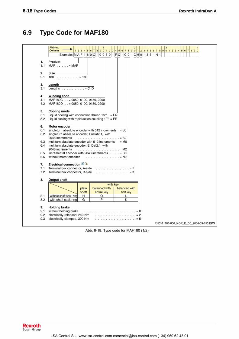
6-18 Type Codes Rexroth IndraDyn A
6.9 Type Code for MAF180
�* +���,���� �0� ������� F�0�
$* -��)�� �-� �������������� F�-�
&* �� ����� .���"7 �������������� F8+1
.* #����� �,��%�� �0��-�8 ��� F��$�+����+��$�+�)��%�) �0��-�1 ��� F��$�+����+��$�+�)��
�* %����� ����$�� .�?@� <��4��;��"<����<�����"��� �*)J F��$�) .�?@� <��4��;��"���� �<����<�@�4���*)J F�3
'* ������,����� 7��4��@���C7�4@����<� ��;��"$�)��<������7 F����) 7��4��@���C7�4@����<� ��+��1��)��+;��"
)�%-��<������7 ��������������������������� F�)��� �@4���@���C7�4@����<� ��;��"$�)��<������7 F����% �@4���@���C7�4@����<� ��+��1��)��+;��"
)�%-��<������7 ��������������������������� F�)��$ ��<�������4��<� ��;��")�%-��<������7 ������ F8���� ;��"�@��������<� �� ���������������������� F��
0* /�,��, ��,���,����,�� !������4C� <����<���+0/7� � ��������������������� F�,�) !������4C� <����<���+2/7� � ��������������������� F�
(* 9�������� 1�
;��"'�H�4��� C�4��<� ;��" C�4��<� ;��"
7"�E� ������'�H "�4E'�H-�� ;��"�@�7"�E�7��4���� � � .-�) ;��"7"�E�7��4���� I & �
4* 5����� �2 "=�� ;��"�@�"�4 ��C��'� ��������������������������������� F�=�) �4�<���<�44H/��4��7� +)%��� �������������������������� F)=�� �4�<���<�44H/<4���� +����� �������������������������� F$
� � � � � ��� � � � � � �
� � � � � � �
�� � � � � � �
��
��������
�$$�%&'�����
� � � � � � � � � � � � � � � � � � � �
$�
RNC-41181-800_NOR_E_D0_2004-09-153.EPS
Abb. 6-18: Type code for MAF180 (1/2)
LSA Control S.L. www.lsa-control.com [email protected] (+34) 960 62 43 01

Rexroth IndraDyn A Type Codes 6-19
��* ������� ���6����� �4����� E�����@���� ��������������������������������� F�$
��* � �� ����� ���� �� ��������������������������������������������������� F����) E��<4@�<"��@���� ������������������������������������������ F3���� ����E��<� C����� �������������������������������������������� F6
�$* 7�2 ������3��6� ��)�� 3 ����������������������������������������������������������� F��)�) � ����������������������������������������������������������� F)�)�� �� ���������������������������������������������������������� F�
���8.��'��E���E�������� �����7"�E�97����<�@���:�4�<���<�4<����<����J�J�� J�J��4H����4�C4������6�C������7������H�� �J�J�7�������4�C4�;��"����E��<� C�����J6J
� � � � � ��� � � � � � �
� � � � � � �
�� � � � � � �
��
��������
�$$�%&'�����
� � � � � � � � � � � � � � � � � � � �
&$�
&
RNC-41181-800_NOR_E_D0_2004-09-154.EPS
Fig. 6-19: Type code for MAF180 (2/2)
LSA Control S.L. www.lsa-control.com [email protected] (+34) 960 62 43 01

6-20 Type Codes Rexroth IndraDyn A
LSA Control S.L. www.lsa-control.com [email protected] (+34) 960 62 43 01

Rexroth IndraDyn A Accessories 7-1
7 Accessories
7.1 Labyrinth SealTo protect the motor output shaft against spraying liquids, IndraDyn Amotors that are already equipped with the "shaft seal" option can beretrofitted with a labyrinth seal (accessory SUP-M02-2AD...).
Labyrinth seal for Type MNRMAD/MAF130 SUP-M02-2AD132 R911273268
MAD160 SUP-M02-2AD160 R911272843
MAF160 SUP-M02-ADF164 R911299702
MAD/MAF180 SUP-M02-2AD180 R911273209
Fig. 7-1: Labyrinth seal
Accessory SUP-M02-xxx... is supplied complete with fastening screwsand assembly instructions.
"
$
�
%
$
�
E
�01*�0�����01*�0�����01*�0��-�
���� ����������������
��
1������%��$,�-$
)
IndraDyn A SUPM02.EPS
(1): Labyrinth seal with fastening screws (scope of delivery)(2): Motor shaft(3): Motor flange(4): Drain hole(5): Max. permitted level of a fluid(h): Thickness of the labyrinth seal
Fig. 7-2: Labyrinth seal the IndraDyn A motors
Note:• Pay attention to the assembly instructions for accessory
SUP-M02-xxx... (in the scope of delivery).• The labyrinth seal is only effective on horizontally-installed
motors and above speeds of approx. 200 rpm. It may only
LSA Control S.L. www.lsa-control.com [email protected] (+34) 960 62 43 01

7-2 Accessories Rexroth IndraDyn A
be installed in motors that have a factory-installed shaftseal.
• Seeping fluids can lead to damage to the motor. Thetightness of the motor seal is ensured only according to theguidelines of the corresponding motor protection class.
7.2 Air-pressure Connector KitThe standard international protection type (IP65) may not be sufficientduring operation under adverse conditions. High demands may be madeon the tightness of motor seals when the motors are used in areas whereoily lubricating coolants are used. For this field of application, werecommend using sealing air for our motors.A defined excess pressure in the motor interior induced by the air-pressure connector kit reliably prevents the penetration of, for example,seeping oil and coolant lubricants.
!�"""!�#$�%
)
�
�
�
�%
���
��4@E��E"��
(1): Splashing water, coolant lubricant(2): Compressed-air line (plastic pipe, type PA 4 x 0.75, or equivalent)(3): Excess pressure inside the motor(4): Air-pressure Connector Kit Accessory
Fig. 7-3: Motor with air-pressure connector kit
Air-pressure connector kits are available as an accessory for IndraDyn Amotors with frame sizes of 100, 130 and 160, as long the motor has aflange socket for its power connection. They are attached by simplyreplacing the motor flange socket cover.
Motor frame sizeMAD/MAF
Motor flangesocket (type)
Description
100 INS0480 SUP-M01-MHD(MNR R911283006)
130160 INS0380 SUP-M02-MHD
(MNR R911283007)
Fig. 7-4: Air-pressure Connector Kit Accessory
Note: Pay attention to the documentation �Sealing Air Accessory forSynchronous Servomotors�, MNR R911283689, as well as theassembly instructions for the accessory set (in the scope ofdelivery).
Ordering Name of AccessorySets
LSA Control S.L. www.lsa-control.com [email protected] (+34) 960 62 43 01

Rexroth IndraDyn A Accessories 7-3
7.3 GearboxesIn certain conditions, two-speed and planetary gearboxes can be attachedto IndraDyn A motors.
Type Gearbox type Requirementat the motor
Supplier
GTS Planetary gearbox 1) Smooth motordrive shaft
Bosch Rexroth
GTM Planetary gearbox 1) Smooth motordrive shaft
ZF Maschinenbetriebe GmbHPostfach 254988015 FriedrichshafenTel. +49-(0)7541-77-0
58... Worm gear2)) Smooth motordrive shaft
ATLANTA Zahnrad- und WerkzeugfabrikSeidenspinner GmbH & Co.Karl-Benz-Str. 1674321 Bietigheim-BissingenTel. +49-(0)7142-7001-0
1) Gearboxes must be ordered as a separate subitem of the motor.2) Bosch Rexroth does not manufacture or supply these gearboxes.
Clarify compatibility and technical details with the manufacturer.
Fig. 7-5: IndraDyn A motors with gearbox
Note: Only low axial shaft loads are permitted for IndraDyn A motors(see Chapter 9.13 �Bearing and Shaft Loads�). Therefore, theIndraDyn A motors are not suitable, or only suitable to alimited degree, for machine elements that generate axialloading of the motors (e.g. helical driving pinions).
LSA Control S.L. www.lsa-control.com [email protected] (+34) 960 62 43 01

7-4 Accessories Rexroth IndraDyn A
LSA Control S.L. www.lsa-control.com [email protected] (+34) 960 62 43 01

Rexroth IndraDyn A Connection Techniques 8-1
8 Connection Techniques
8.1 NotesPower cables and connectors are not in the scope of delivery of themotor. They have to be ordered separately.Bosch Rexroth offers an extensive program of ready-made cables andplug-in connectors that are optimally adapted to the products and to awide range of demands.Decisive advantages of Bosch Rexroth ready-made cables are:• Pre-wired without additional finishing necessary• Laid out for use in applications with continuous bending• Resistant against mineral oils, grease and biologic oils; silicon- and
halogen-free; low adhesion• Use of licensed cables according to UL and CSA• Burning characteristics fulfill VDE0472-804 requirements• Maintain EMC guidelines• Protection class up to IP67
Note: Note that self assembled cables or cable systems of othermanufactures may not fulfill these criteria.Bosch Rexroth shall not be held responsible formalfunction or damages resulting from use of non-BoschRexroth cables.
You can find additional information ...
• on selecting power and encoder cables for IndraDyn A from thefollowing descriptions in this chapter.
• on selecting power and encoder cables for IndraDyn A in theDocumentation �Rexroth Connection Cables�, MNR R911280894.
• for assembling cables and plugs, as well as technical data, in thedocumentation "Rexroth Connection Techniques, Assembling andTools...", MNR R911280895.
LSA Control S.L. www.lsa-control.com [email protected] (+34) 960 62 43 01

8-2 Connection Techniques Rexroth IndraDyn A
8.2 Power ConnectionThe connection of power to IndraDyn A motors is made at the top of themotors and can be established performed via a flange socket or aterminal box.
2/7� �
��"�
4�E�
0/7� �
���
C�����
��@����E���9��4H����@����7�H4�2�$:
Lage_Leistungsanschluss_EN.EPS
Fig. 8-1: Position of the power connection
Note:• When choosing the connection option �flange socket�,
please note that the power cable must be equipped with aplug with a bayonet connection.
• When choosing the connection option �terminal box�,please note that the power cable must be terminated withferrules on conductors U, V and W, and the PE (ground)conductor must be equipped with a ring terminal.
• The design of the power cable also depends on the drivedevice used. Please observe the documentation of thedrive device.
Overview
Terminal boxMotor frame sizeMAD/MAF Flange socket
U-V-W Max. cross section ofpower cable ∅ PE Connection thread
100 INS480 Ferrules 10mm² M6 see motor dimensionsheet
130 INS380 Ferrules 25mm² M8 see motor dimensionsheet
160 INS380 Ferrules 35mm² M8 see motor dimensionsheet
180 not available Ring terminal 50mm² M12 see motor dimensionsheet
Fig. 8-2: Overview power connection
LSA Control S.L. www.lsa-control.com [email protected] (+34) 960 62 43 01

Rexroth IndraDyn A Connection Techniques 8-3
8.3 Power Connection via Flange Socket
���<'������
0�����C7/���4��5���������� �����
0
2
8
��
2���7�*C��'�9�������4:
K
�
�
�
�
)
�
I�*L� 1
0
2
8
1
�
�
�
I
��<"�C�4���� �������
&!8
0
2
8I
� �
�
1
M�
.
0
2
8I
� �
�
1
M�
.
�4��7<" �7����������� G���%-�
�4��7<" �7����������� G����-�
�4��7<" �7�����������
�
)
I
.
-
,
�
$
MAx_Power_Connect1.EPS
(1): The shield connection made in the plug via the cable grip.(2): Only one PTC sensor is wired. The leads for the spare sensor are
found within the plug housing.Fig. 8-3: Layout of power connection in flange socket
Flange SocketThe power connectors of the IndraDyn A motors are equipped with flangesockets with bayonet connections.
�
G����-� G����-�
%�:%;
)
MAx_Power_Plug.EPS
Fig. 8-4: Power connector
1. Insert the plug into the flange socket; pay attention to the coding.2. Manually tighten the union nut until it audibly locks in.3. The red marks on the flange socket and the plug align when the
bayonet connection is properly locked in.
LSA Control S.L. www.lsa-control.com [email protected] (+34) 960 62 43 01

8-4 Connection Techniques Rexroth IndraDyn A
8.4 Power Connection via Terminal Box
0�����C7/���4��5���������� ������
��
2���7�*����9�������4:
K
�
)
�
I�*L�
K�
6�
(�
%
�
)
�
&!8
�4���C���� ������������
&!8
�4���4��7�� �������� ���
�
�
$�
)
,
-
$
�
MAx_Power_Connect2.EPS
(1): Electrically-conducting connection to the motor housing(2): The shield connection must be properly made in the cable via the
cable grip after the cable grip is threaded into the terminal box(3): Only one PTC sensor is monitored. Connect the spare sensor only if
necessary, e.g. because of failure of the first sensor.Fig. 8-5: Layout of power connection in terminal box
Terminal boxIndraDyn A motors designed for drive combinations with higher DC busvoltages - up to 750VDC � are equipped with a terminal strip or terminalblock in the terminal box for the connection of cables with ferrules.
�
)
%
�
$
�
%
MAx_Power_Box.EPS
(1): Cover (2): Seal (gasket)(3): PE (ground) connection (4): Cable entry(5): U-V-W power connection (6): Terminal strip
Fig. 8-6: Terminal box
LSA Control S.L. www.lsa-control.com [email protected] (+34) 960 62 43 01

Rexroth IndraDyn A Connection Techniques 8-5
A schematic diagram of the connection is located in the lid of the terminalbox.
K� 6� (�
N)%6
�6
2���7�2��'�
��4�4�����&!8/��7�7���
��7��>'�4�4�����&!8/��7�7������4�<�����
07H�<"��������07H�<"����@7����� �
)
�
%
$
�
MAx_Power_Box2.EPS
Fig. 8-7: Terminal box connection diagram
Note:• The brake connections are assigned only if the motor was
manufactured with the "brake" option.• Only one contact pair of PTC resistor connectors 3-4 or 5-6
is assigned to the motor cable at one time.• Do not remove or damage the gasket witch is glued to the
cover.• Observe the size of the screwed cable connection and
connection thread for cable inlet into the terminal box.• The connections of the internal winding interconnection in
the terminal box must not be removed.
8.5 Connection Designations on the Drive DeviceThe following overview shows the connection and clamp designations forpower connection, brake connection and motor temperature monitoringon each individual Rexroth drive controller.
Clamp designationsPower Temperature sensor Holding brake
REXROTHDrive Controller
(Terminal block X5) (Terminal block X6)
IndraDrive A1, A2, A3 MotTemp+MotTemp-
+24VBr0VBr
DIAX04 A1, A2, A3 TM+TM-
Br+Br-
ECODRIVE A1, A2, A3 TM+TM-
Br+Br-
Fig. 8-8: Clamp designation on the Rexroth drive controller
LSA Control S.L. www.lsa-control.com [email protected] (+34) 960 62 43 01

8-6 Connection Techniques Rexroth IndraDyn A
8.6 Double CablingA motor connection with two power cables is required if a correspondingsingle cable cannot be used due to the large bending radius or due to itsdimensions.
Note: Double cabling can only be accomplished on motorsequippment with a terminal box (see Fig. 8-6).
3��4��5���������� ������
M
��
$
�
.
&
'
�
0
<7#
(
�$&
�$&
=�>/
=�>/
<7#
+/���$�&
��
+/
+/
�4�����'�7���*����� �����������*��� ��
���>����
&�
&�
0�0)0�
!�/*���!���/
!�N*���!���N
2�/*�62�
2�N*N)%62�
Doppelverkabelung.EPS
Fig. 8-9: Connecting diagram using double cabling diagram
Note:• Conductors not shown in the switching diagram are not
required and must not be connected.• The fuses F1 (NH...), to protect the conductors in case of
overload at cable break, are dimensioned according to thecurrent rating based on the cross-sections of the individualconductor.
• The fuses should be installed in the electrical cabinet sothat they are as close as possible to the power output ofthe drive device.
• The shields of the power cables should be connected to theelectrical cabinet with the largest possible surface area.
• Cable pairs must be properly connected to the terminalstrips or to the terminal studs of the drive controllers; theymust also fulfill safety regulations.
Therefore, observe the following documentation:
LSA Control S.L. www.lsa-control.com [email protected] (+34) 960 62 43 01

Rexroth IndraDyn A Connection Techniques 8-7
• �Electromagnetic compatibility (EMC)...� MNR R911259740• documentation of the motor used• documentation of the drive device used• documentation �Rexroth Connection Cables�, MNR R911282688.
8.7 Encoder ConnectionThe connection of the encoder to IndraDyn A motors is made via a 10-pole, 12-pole or 17-pole flange socket at the motor housing. See thefollowing chart for the connector assignment:
Encoder optionPIN C0 M0 / S0 S2, M21 GN BK A+ BU BK A- BN +US
2 YE BK A- VI SCL WH GND
3 RD R+ YE F Sample GN A+
4 free GY SD in YE A-
5 free YE BK B+ PK B+
6 free GN BK B- GY B-
7 WH GN 0V PK SD out BU data+
8 free RD BK A+ VI data-
9 free free BK clk+
10 BN GN +V WH GN 0V RD clk-
11 BU BK B+ free
12 RD BK B- BN GN +V
13 BK R-
14 free
15 WH 0V Sense
16 BU +5V Sense
17 free
not applicable
not applicable
Fig. 8-10: Overview of encoder connection layouts
LSA Control S.L. www.lsa-control.com [email protected] (+34) 960 62 43 01

8-8 Connection Techniques Rexroth IndraDyn A
���@7�
���@7�
2N
���@7�
���@7�
���@7�
���@7�
0N
0/
3N���@7�
�6
N6
2/3/
�6���7�
N$6���7�
��
�%
�$
��
�,
�4��7<" �7�ED����<'��
���������� ��������G����,=
���<'������
=2��
���
����%�
�4��7<" �7�����������
�
)
�
%
$
�
,
-
=
��
��
�)
0�����C7/���4��5���������� ������
�
�,
�
��
���)
��
MAx_Encoder_C0.EPS
Fig. 8-11: Connection of Encoder Option C0
�4��7<" �7�ED����<'��
���������� ��������G���,��
���<'������
=2��
���
�������-�
0�����C7/���4��5���������� ������
�4��7<" �7����������
�
)
�
%
$
�
,
-
=
��
��
�)
0/
�8.
�7���4�
�1��
2N
2/
�1�@�
0N
���@7�
�6
���@7�
N6
-
,
�$%
�
)
�=
�)��
��
MAx_Encoder_M0-S0.EPS
Fig. 8-12: Connection of Encoder option M0 / S0
�4��7<" �7�ED����<'��
���������� ��������3I�����
���<'���4@
=2��
���
�����$���-
$
0�����C7/���4��5���������� ������
�4��7<" �7�����������
�
)
�
%
$
�
,
-
=
��
NK�
I�1
0N
0/
2N
2/
���N
���/
<4'N
<4'/
-
,
�$
%
�
)
� =��
MAx_Encoder_M2-S2.EPS
Fig. 8-13: Connection of Encoder Option M2 / S2
Connection of Encoder OptionC0
Connection of Encoder optionM0 / S0
Connection of Encoder OptionM2 / S2
LSA Control S.L. www.lsa-control.com [email protected] (+34) 960 62 43 01
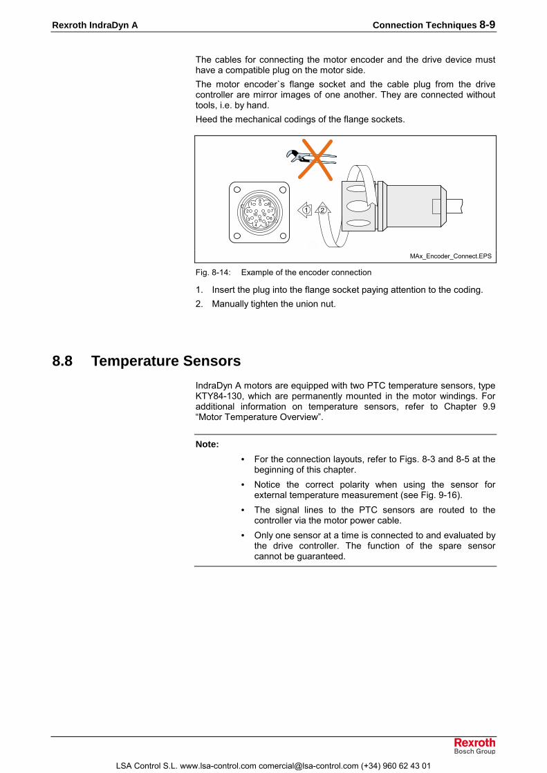
Rexroth IndraDyn A Connection Techniques 8-9
The cables for connecting the motor encoder and the drive device musthave a compatible plug on the motor side.The motor encoder`s flange socket and the cable plug from the drivecontroller are mirror images of one another. They are connected withouttools, i.e. by hand.Heed the mechanical codings of the flange sockets.
-
,
�$%
�
)
�=
�)��
��� )
MAx_Encoder_Connect.EPS
Fig. 8-14: Example of the encoder connection
1. Insert the plug into the flange socket paying attention to the coding.2. Manually tighten the union nut.
8.8 Temperature SensorsIndraDyn A motors are equipped with two PTC temperature sensors, typeKTY84-130, which are permanently mounted in the motor windings. Foradditional information on temperature sensors, refer to Chapter 9.9�Motor Temperature Overview�.
Note:• For the connection layouts, refer to Figs. 8-3 and 8-5 at the
beginning of this chapter.• Notice the correct polarity when using the sensor for
external temperature measurement (see Fig. 9-16).• The signal lines to the PTC sensors are routed to the
controller via the motor power cable.• Only one sensor at a time is connected to and evaluated by
the drive controller. The function of the spare sensorcannot be guaranteed.
LSA Control S.L. www.lsa-control.com [email protected] (+34) 960 62 43 01

8-10 Connection Techniques Rexroth IndraDyn A
8.9 Holding BrakeThe motor holding brake is triggered either directly through the drivedevice or externally.
Note:• For the connection layout, refer to Figs. 8-3 and 8-5 at the
beginning of this chapter.• Control voltage is +24 VDC (+/-10%)• Take note of the functional differences of an electrically-
clamping vs. an electrically-releasing brake (see Chapter9.10 �Motor Holding Brake�).
8.10 Motor Cooling
Blower ConnectionThe motor blower is connected to the power supply system via a cableand motor-protecting switch, and it functions independent of the drivedevice.
&�
�+,$O�+$��)
�+,$O�+$��)
.).�
GPP
GPP
GPP �+,$O�+$��)
.�
�
)
�
��
���>��7<"4@Q����������� ���R��������
�<"@�>7<"�4������ �� ������� ��
���<'���C�� ���������������� ��G���,�$
.DE���������
%
G���,�$
Blower_Connect.EPS
Fig. 8-15: Blower connection diagram
Note:• To establish the connection, the blower plug must be
opened and closed.• The electric connection may only be established by skilled
personnel. Please observe the safety notes.• The seal of the plug housing may not be compromis.• The machine manufacturer selects the motor protecting
switch and the electrical protection. Please observe theregulations in the country of installation.
LSA Control S.L. www.lsa-control.com [email protected] (+34) 960 62 43 01

Rexroth IndraDyn A Connection Techniques 8-11
Connection of Liquid CoolingFor liquid-cooled motors, different connections are possible.
Connection via
Motor MAF ... Threadsnap-on coupling
[Ø di hose] Note100
130G1/4" 9.6 mm
160
180G1/2" 12.7 mm
Selection ofconnection acc. to
type code
Fig. 8-16: Overview of the cooling connections
To supply the MAF motors with cooling liquid, you will need additionalinstallation material, e.g. hoses and fixing clamps. These are not includedin the delivery of the motor. Select the supply hose with the correct innerdiameter di.
The customer�s equipment is threaded directly into the motor. Themotor`s threads are plugged with factory-attached protective caps.In the following illustrations, the assignment of inlet (IN) and outlet (OUT)is made for reasons of standardization; it does not affect the performancedata of the motor. Existing installations with other assignment can beretained.
Operating PressureA maximum coolant supply pressure of 3 bar applies to all MAF motors.This is to be read directly at the coolant connection of the motor.Please note that additional threads or branches connections in the coolingcircuit can have a negative influence on the flow and supply pressure ofthe coolant.
LSA Control S.L. www.lsa-control.com [email protected] (+34) 960 62 43 01

8-12 Connection Techniques Rexroth IndraDyn A
Snap-On CouplingsAnother option for the coolant connection is a snap-on coupling which canalso be released at full pressure, as they have integrated leak protection.
)
�
�F=+���
S
MAF_Liquid_Connect.EPS
Fig. 8-17: Example of coolant connection of a MAF motor
Proceed as follows:⇒ Slip the hose on the motor connection (1). Avoid any bending or
damaging of the screwed connection of the motor.⇒ Screw down the end of the hose over the connection using the hose
clamp (2).⇒ For service purposes, the factory-attached screwed connection can
be released at point �X�. Press the lock in and withdraw the elbow inthe axial direction. It is not necessary to open the hose connection.
If you use another connection technology on the hose side, otherassembly steps may be required. Refer to the manufacture for informationon assembly.
LSA Control S.L. www.lsa-control.com [email protected] (+34) 960 62 43 01

Rexroth IndraDyn A Application Notes 9-1
9 Application Notes
9.1 Operating Conditions
Setup Elevation and Ambient TemperatureThe performance data specified for the motors apply in the followingconditions:
• ambient temperatures of 0º C to +40º C,• elevation between 0 and 1000 m above sea level.
If you want to use the motors in areas with values beyond these ranges,the performance data are reduced according to the following figure.
� )E!
�0�T8����� ����
�+�
�+-
�
%� %$ $� $$ �
E�
"���
�+%
�+�
�+-
�
�+%
ambient.EPS
(1): Utilization factor vs. ambient temperature(2): Utilization factor vs. elevationfT: Utilization factor based on temperaturetA: Ambient temperature in degrees CelsiusfH: Utilization factor based on altitudeh: Setup elevation in meters
Fig. 9-1: Utilization factors
If either the ambient temperature or the setup elevation exceeds thenominal data:1. Multiply the motor data provided in the selection data with the
calculated utilization factor.2. Ensure that the reduced motor data are not exceeded by your
application.
If both the ambient temperature and the setup elevation exceed thenominal data:1. Multiply the determined utilization factors fT and fH by each other.2. Multiply the value obtained by the motor data specified in the
selection data.3. Ensure that the reduced motor data are not exceeded by your
application.
LSA Control S.L. www.lsa-control.com [email protected] (+34) 960 62 43 01

9-2 Application Notes Rexroth IndraDyn A
9.2 HumidityEnvironmental conditions are differentiated by class according to DIN EN60721-3-3 (1995), Table 1. They are based on observations made overlong periods of time throughout the world and take into account all supplyparameters that could have an effect, such as the air temperature andhumidity.Based on this table, Rexroth recommends class 3K4 for continuous useof the motors.The following table provides an excerpt of this class:
Environmental factor Unit Class 3K4
Min. air temperature °C +5 1)
Max. air temperature °C +40
Min. rel. humidity % 5
Max. rel. humidity % 95
Min. absolute humidity g/m³ 1
Max. absolute humidity g/m³ 29
Speed of temperaturechange °C/min 0.5
1) Rexroth permits 0°C as the lowest air temperature.
Fig. 9-2: Classification of climatic environmental conditions according to DINEN 60721-3-3, Table 1
9.3 Vibration and Shock
VibrationVibrations occur in stationary use and, depending on their intensity, havedifferent effects on the robustness of the motors.The robustness of the overall system is determined by the weakestcomponent.Based on DIN EN 60721-3-3 and DIN EN 60068-2-6, the following valuesare permissible for Rexroth motors:
Direction Amplitude0 – 55 Hz
Acceleration55 – 2000Hz
axial 0.3 mm 1 m/s²
radial 0.75 mm30 m/s²
(10 m/s² when used with M2/S2encoders)
Fig. 9-3: Maximum values for vibrations
LSA Control S.L. www.lsa-control.com [email protected] (+34) 960 62 43 01

Rexroth IndraDyn A Application Notes 9-3
ShockThe shock load of the motors is indicated by providing the maximumpermitted acceleration in non-stationary use, e.g. during transport.Prevent damage to the motor by avoiding shocks which exceed theprovided limits.Based on DIN EN 60721-3-3 (1995), the following values apply forIndraDyn A motors:
Maximum permissible shock load(duration 11ms)
Motor frame size axial radial100 .... 180 10 m/s² 150 m/s²
Fig. 9-4: Maximum values for shock load
Note: Please also observe the specifications in Chapter 10.4�Transportation and Storage�.
The construction and effectiveness of shock-absorbing or shock-decoupling attachments depends on the application and must bedetermined using measurements. This does not lie within the area ofresponsibility of the motor manufacturer. Modifications to the motor resultin nullification of the warranty.
9.4 Compatibility with Foreign MaterialAll Rexroth drive-and-control devices are developed and tested accordingto the state-of-the-art.However, as it is impossible to follow the continual development of allmaterial which may come into contact with our drives and controllers, e.g.lubricants for machine tools, we cannot, in general, exclude any reactionwith the materials used in our systems.For this reason, you will have to carry out a test of compatibility betweennew coolants, lubricants, detergents, etc. and our housing/our housingmaterials.
LSA Control S.L. www.lsa-control.com [email protected] (+34) 960 62 43 01

9-4 Application Notes Rexroth IndraDyn A
9.5 Degree of ProtectionThe degree of protection acc. to IEC 60529 applies for IndraDyn Amotors. In all installation positions of the motor, it must be ensured thatthe motors are not subjected to ambient conditions that exceed the validdegree of protection.The degree of protection is defined by the abbreviation IP (InternationalProtection) followed by two reference numbers, which specify the degreeof protection. The first number describes the degree of protection againstcontact and penetration of foreign substances; the second numberdescribes the degree of protection against penetration by water.
��
%
)
MAD_Application4.EPS
Fig. 9-5: Protection classes
Motor area Degree ofprotection
Note
(1) Output shaft withoutshaft seal IP 54 IP40 in vertical installation
(see Fig. 9-10)(1) Output shaft with shaft seal IP 65 Option(1) Output shaft with labyrinthseal IP 65 Accessory; seal effective starting
at 200 rpm.
(2) Power and feedbackconnections IP 65 Terminal box
or plug(3) Motor encoder connection IP 65
(4) Motor blower IP 65 Blower motor IP 65Blower screen IP 24
Fig. 9-6: Motor protection class ranges
In every installation position be sure that the motors are not subjected toambient conditions whitch exceed the applicable degree of protectionaccording to IEC 60529.
Products and ranges with a low degree of protection are not suitedfor cleaning procedures with high pressures, vapors or water jets.
LSA Control S.L. www.lsa-control.com [email protected] (+34) 960 62 43 01

Rexroth IndraDyn A Application Notes 9-5
9.6 Design and Installation PositionIndraDyn A motors can be delivered in designs B05 and B35. Please referto the table below for the conditions of installation permissible accordingto EN 60034-7.
Permissible conditions of installationMotordesign Description Sketch Setup
IM B5Flange mounting onthe drive end of theflange
IM V1
Flange mounting onthe drive end of theflange; drive sidepointing downB05
IM V3
Flange mounting onthe drive end of theflange; drive sidepointing up
IM B3 Base (foot) mounting,feet at the bottom
B35
IM B5Flange mounting onthe drive end of theflange
Fig. 9-7: Installation positions
IndraDyn A motors with a B35 design can be mounted by using the foot-assembly or the flange-assembly method.
)
�MAFMount2.EPS
(1): Mounting feet(2): Flange for flange assembly
Fig. 9-8: Methods of mounting the IndraDyn A
In the case of foot mounting, the forces of the load may only act in thevertical direction perpendicular to and towards the plain of feet (± 15°).The transfer of forces with other effective force directions is not permitted.
LSA Control S.L. www.lsa-control.com [email protected] (+34) 960 62 43 01

9-6 Application Notes Rexroth IndraDyn A
?���@
)
�
?���@
)
�?� ��@)
�
?� ��@ )
�
))
)
)
)
)
)
?���@ ?
���@
MAFMount.EPS
(1): Mounting feetFig. 9-9: Acceptable foot-mounting layouts
Notes:• Forces transferred from a gearbox must not act on the feet
of the motor; they must be supported by the gearbox itself.• An improper installation situation results in forces that can
quickly lead to motor damage.• Consider the alternative "flange mounting".
Vertical AssemblyIn the case of vertical installation positions as shown in the figure below,dirt and fluids can more easily enter the motor interior and causemalfunctions or break downs.
G�6� G�6�
��
MAFMount3.EPS
(1): Shaft duct IP 40 (standard)Shaft duct with radial shaft seal IP 65 (option)
Fig. 9-10: Motor installed vertically
LSA Control S.L. www.lsa-control.com [email protected] (+34) 960 62 43 01

Rexroth IndraDyn A Application Notes 9-7
Notes:• A side: The degree of protection on the flange side of
motors with a shaft seal is IP 65. However, the seal isensured only in case of splashing water. Liquid levelspresent on the shaft end require a higher degree ofprotection.
• B side: The degree of protection for the blower screens inaxial blowers is IP 24. Chips or larger dirt particles canpenetrate the blower screen as well.
• Protection class: The factory-attached protection class ofIndraDyn A motors must not be reduced by modificationsor by retrofitting accessories.
⇒ Already take the installation position and the protection class of themotors into account when planning the system.
9.7 Housing PaintThe paint use of the motor housing consists of a black (RAL9005) 2K-Epoxydharz coating based on Epoxyd-Polyamid-Resin in water.
Chemically resistant against Limited resistant against Impermanent againstattenuated acids/brines organic solvents concentrated acids/brines
Water, sea-water, sewage hydraulic oil
common machine oils
Fig. 9-11: Varnish-resistance
The housing may be repainted, but the coat thickness may be nomore than 40 µm. Check the adhesion and resistance of the new paintbefore painting.
LSA Control S.L. www.lsa-control.com [email protected] (+34) 960 62 43 01

9-8 Application Notes Rexroth IndraDyn A
9.8 Motor Cooling
BlowerMAD motors may be operated only with blowers. Cooling occurs using aircurrents that are guided through air plates over the surface of the motor.An axial blower is used for cooling purposes. The blower is only availablewith the �blowing� option. Observe the information in the type code.A minimum distance between the blower screen and the machine mustbe maintained to ensure that the required air volume can flow through theblower and out of the front of the motor. See Chapter 4, "Technical Data".The distance (2) is determined by the motor construction.
(�����
)�
MAD_Application5.EPS
(1): Machine housing(2): Blower Exhaust(3): Blower In-take
Fig. 9-12: MAD ventilation
⇒ Observe the air flow in the machine construction. The minimumdistance is 80 mm for all MAD motors.
⇒ The design for all blower variants is "blowing".
Contamination will reduce the performance of the blowers and can lead tothermal overload of the motors.When the machine is installed in an unclean environment, regularlycleaning the blower and motor radiator fins will increase the lifetime ofyour motor.
When designing the machine, take into account accessibility tothe motors and blowers for maintenance purposes.
LSA Control S.L. www.lsa-control.com [email protected] (+34) 960 62 43 01

Rexroth IndraDyn A Application Notes 9-9
CoolantsMAF motors must always be operated with an external cooling system.The energy losses of the motor, P(v), are dissipated through the coolingsystem. Accordingly, MAF motors may only be operated if proper coolantflow is ensured. The cooling system has to be rated by the machinemanufacturer in such a way that all requirements regarding flow,pressure, purity, temperature gradient etc. are maintained at all times.
CAUTION
Impairment or loss of motor, machine orcooling system!⇒ Consider absolutely the motor data and the
explanations and conceptions of the cooling systemsin the documentation �Liquid cooling, dimensioning,selection�, MNR R911265836.
⇒ Consider the manufacturer instructions atconstruction and operation of cooling systems.
⇒ Do not use any lubricants or cutting lubricants fromoperating processes.
All details and technical data refer to water as a coolant. When usingother coolants, these data are no longer valid and must be recalculated.Cooling using tap water is not recommended. Hard water can causedeposits or corrosion and damage the motor and the cooling system.For corrosion protection and for chemical stabilization, the cooling watermust have an additive which is suitable for mixed-installations with thematerials acc. to Fig. 9-13.The utilization of aggressive coolants, additives, or cooling lubricants cancause irreparable motor damages.
⇒ Use a recirculating system with a fine filter ≤ 100 µm.⇒ Consider the environmental protection and waste disposal
instructions at the place of installation when selecting the coolant.
Aqueous solutions ensure a reliable corrosion protection withoutsignificant changes to the physical property of the water. Therecommended additives contain no harmful materials to water.
Corrosion protection oils for coolant systems contain emulsifiers whichensure a fine allocation of the oil in the water. The oily components of theemulsion protect the metal surface of the coolant duct against corrosionand cavitation. Herewith, an oil content of 0.5 � 2% by volume has proveditself.If the corrosion protection oil must not only provide corrosion protectionalso provide lubrication of the cooling pump, then the oil content of 5% byvolume is necessary.
⇒ Note the regulations of the pumping manufacturer!
Aqueous Solution
Emulsion with CorrosionProtection
LSA Control S.L. www.lsa-control.com [email protected] (+34) 960 62 43 01

9-10 Application Notes Rexroth IndraDyn A
Example for coolant additives:
Description Manufacturer1%...3%-solutionsAquaplus 22 Petrofer, Hildesheim
Varidos 1+1 Schilling Chemie, Freiburg
33% solutionsGlycoshell Deutsche Shell Chemie GmbH, Eschborn
Tyfocor L Tyforop Chemie GmbH, Hamburg
OZO frost protection Deutsche Total GmbH, Düsseldorf
Aral coolant frost protection A ARAL AG, Bochum
BP antifrost X 2270 A Deutsche BP AG, Hamburg
emulsifiable mineral oil concentrateShell Donax CC (WGK: 3) Shell, Hamburg
Fig. 9-13: Coolant Additives
Note: Bosch Rexroth can give no general statements orinvestigations regarding applicability of process-relatedcoolants, additives, or operating conditions.The performance test for the used coolants and the design ofthe liquid coolant system are in the responsibility of themachine manufacturer. See also Chapter 9.4 �Compatibility�.
Materials used in the Cooling SystemWhen used with MAF motors, the coolant comes into contact with thefollowing materials:
Motor, housing Threaded connections Snap-on coupling
Cu, CuZn39Pb2 Chromium-plated Brass Chromium-plated Brass
Fig. 9-14: MAF material
In dimensioning and operating the cooling system, the machinemanufacturer has to consider and prevent all chemical or electro-chemical interactions while ensuring against corrosion or decompositionof motor parts.
Coolant Additives
LSA Control S.L. www.lsa-control.com [email protected] (+34) 960 62 43 01

Rexroth IndraDyn A Application Notes 9-11
Inlet Temperature of CoolantIndraDyn A motors have been designed acc. to DIN EN 60034-1 foroperation with coolant temperature of +10...+40°C. This temperaturerange must be observed at all times. With higher coolant temperatures,the reduction of the available torque is increased. Because of hightemperature gradients, lower coolant temperatures can lead to destructionof the motor.
Note: Install systems in the cooling circuit to monitor flow, pressure,and temperature.
Setting the inlet temperature of the coolant must be carried out observingthe specified temperature range and taking into account the existingambient temperature.The lower threshold of the recommended coolant inlet temperature maybe limited depending on the existing ambient temperature. To avoidcondensation, the lowest allowable coolant temperature may be max. 5°Cbelow the existing ambient temperature.
Example 1:Permissible range of coolant inlet temperature: +10... +40°CAmbient temperature +20°CCoolant inlet temperature to be set: +15... +40°C
Example 2:Permissible range of coolant inlet temperature: +10... +40°CAmbient temperature +30°CCoolant inlet temperature to be set: +25... +40°C
Setting the Inlet Temperature
LSA Control S.L. www.lsa-control.com [email protected] (+34) 960 62 43 01

9-12 Application Notes Rexroth IndraDyn A
9.9 Motor Temperature OverviewIn their standard configuration, stators of IndraDyn L motors are equippedwith built-in motor protection temperature sensors.These have nearly a linear characteristic curve (see Fig. 9-16).
Type KTY84-130
Resistor at 25°C 577 Ohm
Resistor at 100°C 1000 Ohm
Continuous current at 100°C 2 mA
Fig. 9-15: Temperature measurement sensor
Note: To avoid damage, observe the correct polarity when using thesensor for external temperature measurement .
temperature measuring sensor KTY84-130connecting cores brown (+) und white (-)
500
600
700
800
900
1000
1100
1200
1300
1400
1500
10 20 30 40 50 60 70 80 90 100 110 120 130 140 150 160 170
motor winding temperature in °C
tem
pera
ture
sen
sor r
esis
tanc
e in
ohm
s
Fig. 9-16: Characteristic sensor temperature measurement KTY84-130 (PTC)
Temperature Measurement ofSensors
LSA Control S.L. www.lsa-control.com [email protected] (+34) 960 62 43 01

Rexroth IndraDyn A Application Notes 9-13
9.10 Motor Holding Brake (Option)In normal operation, use the brake only when at a standstill and whenperforming the drive-internal brake check. The motor holding brake isrequired for holding the axes when the machine is in a de-energized state.
CAUTION
Hazardous movements! Persons endangered byfalling or descending axes!⇒ Observe supplementary DIN and guidelines. For
European countries:- DIN EN 954 / 03.97 on security-related parts ofcontrollers.- Instruction sheet for vertical axisEditor:Süddeutsche Metall-BerufsgenossenschaftFachausschuss Eisen und Metall IIWilhelm-Theodor-Römheld-Str. 1555130 Mainz, Germany
USA: See National Electric Code (NEC), NationalElectrical Manufacturers Association (NEMA) as wellas local building regulations.The following is generally valid: the nationaldestinations must be observed!
⇒ he serially delivered motor holding brake does notsuffice to ensure personal protection!
⇒ Ensure personal protection by superordinate fail-safemeasures.
⇒ Cordon off the hazardous area by means of a safetyfence or a safety screen.
⇒ Additionally secure vertical axes to prevent themfrom sinking or descending after having shutdownthe motor, for instance as follows:- lock the vertical axes mechanically,- provide an external braking / collecting / clampingdevice, or- ensure sufficient weight compensation of the axes.- Miscellaneous suitable measures
The brake�s control mechanism must ensure this function in normaloperation. Under the worst-case load condition of the power supply, avoltage of 24 VDC +/- 10% must be provided the motor brake. To identify afailure in time during operation, the power supply for the brakes must bemonitored by an undervoltage detection system.
Brake Control
LSA Control S.L. www.lsa-control.com [email protected] (+34) 960 62 43 01

9-14 Application Notes Rexroth IndraDyn A
Before startup and during operation specifications, the brake functionmust be tested with the �brake command� function. By applying a smallamount of motor torque, the brake is checked for slippage. Additionalinformation and specifications of this function may be found in theECODRIVE firmware functional descriptions.
Selecting Holding BrakesBrakes are either electrically-clamped or electrically-released. Due tofunctional differences, different brakes should be used for main-spindleand for servo-axes. Observe the safety requirements during the systemdesign.
�
� )
K��6�
�
)%
K��6�
�
)%
���)�� �)
�
brake.EPS
(1): Electrically-clamped brake(2): Electrically-released braket1: Clamp delayt2: Releasing time
Fig. 9-17: Holding brake diagram
Main Spindle ApplicationsAn electrically-clamped holding brake can be used to lock a mainspindle during standstill and when the control �controller enable� signal isoff, e.g. when a tool change is performed without a closed position loop.
⇒ Clamp the motor only at standstill, i.e. after the controller has signaledthe motor is at standstill.
An electrically-released holding brake should not be used on mainspindles. Unintentional clamping of the holding brake at high motorspeeds can lead to extreme deterioration or even demolition of the brake(e.g. in the case of power loss or wire breakage).
Functional test
Electrically-clamped HoldingBrake
LSA Control S.L. www.lsa-control.com [email protected] (+34) 960 62 43 01

Rexroth IndraDyn A Application Notes 9-15
Servo ApplicationsAn electrically-released holding brake is used to hold the axes at astandstill and when the �controller enable (rF)� signal is off. When thepower supply voltage is lost or the rF-enable signal is LOW, theelectrically-released brake will automatically close (engage).
⇒ Do not use the holding brake as an service brake for moving axes.
If the brake is engaged repeatedly on a drive in motion or the rated braketorque is exceeded, premature brake wear can occur.The electrically-clamping holding brake is inappropriate for servoapplications, because clamping in a de-energized clamping state is notpossible.
Dimensioning of Holding Brakes (Application)The physical conditions of holding brakes require consideration of twostates. In addition to normal operation, fault conditions must also beconsidered. The effective braking torques are physically different.
Normal OperationIn normal operation, i.e. using the holding brake for clamping of an axisat standstill, the brake�s static-torque (M4) rating in the data sheetsapplies - directly as static holding torque (M4) - static friction (frictioncoefficient µH).
Fault Condition (EMERGENCY STOP)In fault conditions (i.e., EMERGENCY STOP), i.e. when the holdingbrake is used to stop a moving axis, the �dynamic braking torque�, orsliding friction applies - friction coefficient µG.The dynamic braking torque is reduced in comparison to the indicatedstatic holding torque M4. Therefore, note the following description ofdynamic dimensioning.
The load torque must be smaller than the minimum dynamic torque whichthe brake can provide. Otherwise the dynamic brake torque is notsufficient to stop the axis.If a mass is to be decelerated in a defined time or in a defined route, theadditional mass moment of inertia of the whole system must be taken intoaccount.
Electrically-released HoldingBrake
Dynamic Dimensioning
LSA Control S.L. www.lsa-control.com [email protected] (+34) 960 62 43 01

9-16 Application Notes Rexroth IndraDyn A
Further Important Aspects for Dimensioning:The holding brake is not a safety brake (see DIN EN 954 / 03.97 andvertical axis data sheet SMBG). Due to uncontrollable influencing factorssuch as a rust-film generation on the friction surface, the brake holdingtorque can be reduced. Additionally, over voltages and temperatures canweaken the permanent magnets and the brake.
Bringing these factors together, the following recommendations can begiven for dimensioning the holding brakes to the axles.The necessary holding torque required for the application must notexceed a maximum of 60% of the static holding torque (M4) of thechosen holding brake.
Note: Holding-torque reduction and premature deteriorationoccur when braking moving axes!
Do not use the holding brake to stop a moving axis! This is permitted forEMERGENCY STOP situations only. In this situation, the specified ratedtorque of the holding brake (M4) is reduced to the value of the availabledynamic-braking torque. Complete deterioration of the brake`s holdingcapacity can be expected after approximately 20,000 revolutions of aclamped/closed brake.
Observe the instructions on commissioning holding brakes as describedin Chapter 12, �Startup, Operation, and Maintenance�.
Dimensioning Recommendation
LSA Control S.L. www.lsa-control.com [email protected] (+34) 960 62 43 01

Rexroth IndraDyn A Application Notes 9-17
9.11 Motor Encoder
Options"S0": Single-turn incremental encoder with I²C interface. 1Vpp sine/cosinesignals with 512 lines per revolution and absolute period assignmentwithin one shaft rotation.
“S2” Single-turn incremental encoder with EnDat2.1 interface. 1Vppsine/cosine signals with 2048 lines per revolution and absolute periodassignment within one shaft rotation. The encoder is equipped with a datamemory that already contains all relevant motor data required for puttingthe motor into operation.
"M0": Multi-turn incremental encoder with I²C interface. 1Vpp sine/cosinesignals with 512 lines per revolution and absolute period assignmentwithin 4096 shaft rotations. The shaft position is stored if the power fails.
�M2�: Multi-turn incremental encoder with EnDat2.1 interface. 1Vppsine/cosine signals with 2048 lines per revolution and absolute periodassignment within 4096 shaft rotations. The shaft position is stored if thepower fails. The encoder is equipped with a data memory that alreadycontains all relevant motor data required for putting the motor intooperation.
"C0": Incremental encoder, sine/cosine signal-1Vpp with 2048 lines perrevolution.
"N0": The motor is supplied without a factory-installed encoder unit. Therear of the motor is protected by a cover.
CompatibilityDue to different encoder technologies, the motor encoders can beconnected to only certain drive controllers and interfaces. The encoderdata must be parameterized in the controller. The compatibility can beseen in the following table:
ECO03 DIAX04 IndraDrive
Encoderoption
DKC16...400
HDD,HDS
ADVANCED BASIC OPENLOOP
BASICSERCOS
BASICPROFIBUS
BASICANALOG
BASICUNIVERSAL
C0 + + + - - - - +
M0 + + + - - - - +
M2 - - + + + + + +
S0 + + + - - - - +
S2 - - + + + + + +
+ compatible - incompatible
Fig. 9-18: Encoder compatibility
LSA Control S.L. www.lsa-control.com [email protected] (+34) 960 62 43 01

9-18 Application Notes Rexroth IndraDyn A
Accuracy/RepeatabilityThere are two types of accuracy for rotary encoders: "absolute accuracy"and "relative accuracy".The absolute accuracy of rotary encoders is determined primarily by thequality and precision of the encoder construction as well as by themechanical attachment to the motor.The following values apply to IndraDyn A motors:
Encoder optionacc. to typecode Technical data
Absoluteaccuracy
C0 Incremental encoder, sinus/cosine signal1Vpp with 2048 lines/rev
± 0.0056°(± 20" )
M0
Multi-turn incremental encoder with I²Cinterface.
Incremental encoder, sinus/cosine signal1Vpp with 512 lines/rev
± 0.0167°(± 60" )
M2Multi-turn incremental encoder with
EnDat2.1 interface. Incremental encodersinus/cosine signal 1Vpp with 2048 lines/rev
± 0.0056°(± 20" )
S0Single-turn incremental encoder with I²C
interface. Incremental encodersinus/cosine signal 1Vpp with 512 lines/rev
± 0.0167°(± 60" )
S2Single-turn incremental encoder with
EnDat2.1 interface. Incremental encodersinus/cosine signal 1Vpp with 2048 lines/rev
± 0.0056°(± 20" )
Fig. 9-19: Absolute accuracy of encoder
The relative accuracy of encoder systems is also referred to as"repeatability". It is determined primarily by the interpolation variancesduring further processing of the measured signals in the internal andexternal interpolation - and digitization electronics.For IndraDyn A motors, the following guidelines apply for operation withRexroth drive controllers (as of the publishing date of this documentation):
Encoder optionacc. to typecode Technical data
Relativeaccuracy
C0 Incremental encoder, sinus/cosine signal1Vpp with 2048 strokes ± 0.01'
M0
Multi-turn incremental encoder with I²Cinterface.
Incremental encoder, sinus/cosine signal1Vpp with 512 lines/rev
± 0.005'
M2Multi-turn incremental encoder with
EnDat2.1 interface. Incremental encodersinus/cosine signal 1Vpp with 2048 lines/rev
± 0.005'
S0Single-turn incremental encoder with I²C
interface. Incremental encodersinus/cosine signal 1Vpp with 512 lines/rev
± 0.001'
S2Single-turn incremental encoder with
EnDat2.1 interface. Incremental encodersinus/cosine signal 1Vpp with 2048 lines/rev
± 0.001'
Fig. 9-20: Relative encoder precision
Continuous development of the hardware and firmware for drivecontrollers may result in variances from the above values. Therefore,
Absolute Accuracy
Relative Accuracy“Repeatability”
LSA Control S.L. www.lsa-control.com [email protected] (+34) 960 62 43 01

Rexroth IndraDyn A Application Notes 9-19
always observe the information in the most-current drive controllerdocumentation.
The accuracy of encoder systems is only a secondary factor forthe precision of processing and positioning processes in a system.Determining factors for the precision that can be attained include thefunctions of the system and the quality of the mechanical construction,among other things.
Connection of the EncoderThe encoder connection is always on the same side of the motor as thepower connection. The position of the encoder connection can not bechanged after the motor has been delivered. For additional details, referto the dimension sheet of the motor and to Chapter 8 "ConnectionTechnique".
Detailed information on the encoder connection to the controller,and on the setting of its parameters can be found in the documentation ofthe drive controllers.
9.12 Output Shaft
Plain ShaftThe recommended standard model for all IndraDyn A motors provides afriction-type, zero-backlash, shaft-hub connection with a high degree ofquietness. Use clamping sets, thrust sleeves or clamping elements tocouple the machine elements to be driven by the motor.
Output Shaft with KeyAn optional keyed output shaft, according to DIN 6885, Sheet 1, edition08-1968, permits form-fitting transmission of torque for non-reversing withlow requirements on the shaft-hub connection.
�
)
�
%
MADDetails3.EPS
(1): Key (2): Keyway(3): Motor drive shaft (4): Center hole
Fig. 9-21: Output shaft with key
LSA Control S.L. www.lsa-control.com [email protected] (+34) 960 62 43 01

9-20 Application Notes Rexroth IndraDyn A
The machine elements to be driven must additionally be secured in theaxial direction via the centering hole in the front of the shaft.
Note: Avoid strong reversing operations. Deformations to the keywaycan lead to breakage of the shaft.
The motor is balanced with a half key. The mass relationships are similarto those for a plain shaft. Inserting a complete key results in an imbalancethat must be compensated on the machine element that is to be driven.The hub of a machine element that is to be driven (pinion, pulley, etc.)should correspond to the key length.
Note: If the hub is shorter, use a graduated key.
The motor is balanced using the included key. Hence, the machineelement to be driven must be balanced without a key. The keyway lengthin the hub is independent of the length of the key.
Modifications to the key may be made only by the user himselfand on his own responsibility. Bosch Rexroth does not provide anywarranty for modified key or motor drive shafts.
Output Shaft with SealIf the IndraDyn A motor is ordered with the optional radial shaft sealaccording to DIN 3760 � Design A, they can be mounted to transmissionswith oil bath or circulating-oil lubrication, applied dusty environments, oroperated in moist rooms.
Note: In case of open, oil-lubricated gearboxes, excessive mist orspeeds above 4000min-1, we recommend an additionallabyrinth sealing which can be ordered and retrofitted as anaccessory (refer to Chapter 7 �Accessories�).
MADDetails1.EPS
Fig. 9-22: Shaft seal
Radial shaft seals are friction seals. Hence, they are subject todeterioration and generate frictional heat.
Balancing with a Half Key
Balancing with a Full Key
Deterioration
LSA Control S.L. www.lsa-control.com [email protected] (+34) 960 62 43 01

Rexroth IndraDyn A Application Notes 9-21
Deterioration of the friction seal can be reduced only if lubrication issufficient and if the point of contact is clean. Here, the lubricant also actsas a coolant, supporting the discharge of frictional heat from the contactarea. The lifetime of the lip seal on the radial shaft seal depends on howclean it is, on the lubrication and on the motor speed.
Note: Prevent the surface area near the seal from becoming dry anddirty. Always ensure sufficient cleanliness and lubrication.
The materials used for the shaft seal are highly resistant to oils andchemicals. The performance test for the particular operating conditionslies, however, within the machine manufacturer�s responsibility.As of the publication date of this document, the following materialassignment is applicable:
Motor MAD/MAF … Sealing material Abbreviation100...160 Polytetrafluorethylene PTFE
180 Viton FKM
Fig. 9-23: IndraDyn A shaft seal
The complex interactions between the seal, the shaft and the fluidto be sealed, as well as the particular operating conditions (frictional heat,soiling, etc.), do not allow for an exact calculation of the lifetime of theshaft seal.
With a circumferential speed of 5 m/s and in favorable conditions (e.g.sufficient cleanliness and lubrication), a lifetime of between 5,000 and10,000 h can nevertheless be achieved.
The international protection rating on the flange side of motors with anoptional shaft seal is IP 65. Hence, impermeability is only ensured againstsplashing fluids. Liquid levels present on the motor-output side require ahigher degree of protection. In the case of vertical installations, also heedthe notes in Chapter 9.6 "Vertical Installation".
Resistance to Oil and Chemicals
Vertical Mounting PositionsIM V3/IM V6
LSA Control S.L. www.lsa-control.com [email protected] (+34) 960 62 43 01

9-22 Application Notes Rexroth IndraDyn A
9.13 Bearing and Shaft LoadsDuring operation, both radial and axial forces act upon the motor driveshaft and, thus, upon the bearings. Machine design and motor type mustbe carefully adapted to make sure that the specified load limits are notexceeded.
Radial Load, Axial Load
(���
��������
'����#(�������������
'����#�)�#��**+�,�%����������� ����
-�)����#�)-��-�.�%�(�#�)-��
�� ��4
��� ��4
�%�,)��/���
AHbsp_WB.EPS
Fig. 9-24: Example of a shaft load diagram
The maximum permissible radial force Fradial_max depends on the followingfactors:• Shaft-breaking stress• Point of force application, x (see Fig. 9-24)• Shaft design (smooth; with keyway)
The permitted radial force Fradial depends on the following factors:• Arithmetic mean speed (nmean)• Point of force application x (see Fig. 9-24)• Bearing Lifetime
Only low axial shaft loads are permitted on IndraDyn A motors.
MAD/MAF 100 130 160 180permissible axialload [N] 30 50
Fig. 9-25: Axial load
The permitted axial load applies for all installation positions. Therefore,the motors are not suitable for machine elements that generate axialloading of the motors (e.g. helical driving pinions).
Note: Avoid impermissible axial loads or jolting of the motor driveshaft.
The acceleration and deceleration times can be ignored in the calculationif the time during which the drive is operated at a constant speed is
Maximum Permissible RadialForce Fradial_max
Permissible Radial Force Fradial
Permissible Axial Force Faxial
Mean Speed
LSA Control S.L. www.lsa-control.com [email protected] (+34) 960 62 43 01

Rexroth IndraDyn A Application Notes 9-23
significantly greater than the acceleration and deceleration times. In theexact calculation of the mean speed according to the following example,the acceleration and deceleration times are taken into account.
�
�
��� �� �2� ��� ��) �) �2) �))
��
�)
Average.EPS
111B11H
1B1
111H1
m1 tttt
t2ntnt
2n
n+++
⋅+⋅+⋅=
n1m: mean speed in section 1 n2m: mean speed in section 2n1: processing speed n2: processing speedtH1: acceleration time tH2: acceleration timet1: processing time t2: processing timetB1: deceleration time tB2: deceleration timet11: standstill time t22: standstill time
Fig. 9-26: Mean speed
A complete operating cycle can consist of several sections with differentspeeds. In this case, the average is to be generated from all the sections.
�6��A�A���ABA
�� F�������/�
��F)������/�
��F%������/���F-������/�
)
��F$�����/�
�
�
�
)
�
%
$
� �� )� �� %� $� ��
C�����
)��"��
�6��A5A
��F$�����/�
�� F�������/�
��F)������/�
��F%������/�
��F��������/�
�
�+$
�
�+$
)
� �� )� �� %� $� ��
C�����
)��"��
Wellenbelastung MAx100.EPS
"N": Standard bearings�R�: Bearing for coupling attachment�H�: High-speed bearing(1): Load limit for drive shaft without keyway(2): Load limit for drive shaft with keywaynm: Mean speed
Fig. 9-27: Shaft load, Motor-frame size 100 (Lh=30,000 operating hours)
Shaft Load, Size 100
LSA Control S.L. www.lsa-control.com [email protected] (+34) 960 62 43 01

9-24 Application Notes Rexroth IndraDyn A
��F$�����/�
�� F�������/�
��F)������/�
��F%������/�
��F,$�����/�
�
�
)
�
%
$
� )� %� �� -� ��� ���
C�����
)��"��
�6��A�A���ABA
$
�6��A7A
��F�������/�
��F)������/�
��F%������/�
��F,$�����/�
)�
��F$�����/�
�
)
%
�
-
��
� )� %� �� -� ��� ���
C�����
)��"��
�6��A5A
��F$�����/�
��F�������/�
��F)������/�
��F%������/�
��F=������/�
�
�+$
�
�+$
)
)+$
� )� %� �� -� ��� ���
C�����
)��"��
Wellenbelastung MAx130.EPS
"N": Standard bearings�R�: Bearing for coupling attachment�V�: Reinforced bearing�H�: High-speed bearing(1): Load limit for drive shaft without keyway(2): Load limit for drive shaft with keywaynm: Mean speed
Fig. 9-28: Shaft load, Motor-frame size 130 (Lh=30,000 operating hours)
�6��A�A���ABA
��F$�����/�
�� F�������/�
��F)������/�
��F%������/���F�������/�
�
)
�
%
$
�
,
� )� %� �� -� ��� ���
C�����
)��"��
�6��A7A
��F$�����/�
�� F�������/�
��F)������/�
��F%������/���F�������/�
)
)
%
�
-
��
�)
�%
� )� %� �� -� ��� ���C�����
)��"��
Shaft Load MAx160.EPS
"N": Standard bearings�R�: Bearing for coupling attachment�V�: Reinforced bearing(1): Load limit for drive shaft without keyway(2): Load limit for drive shaft with keywaynm: Mean speed
Fig. 9-29: Shaft load, Motor-frame size 160 (Lh=30,000 operating hours)
Shaft Load, Size 130
Shaft Load, Size 160
LSA Control S.L. www.lsa-control.com [email protected] (+34) 960 62 43 01

Rexroth IndraDyn A Application Notes 9-25
�6��A7A
��F�������/�
��F)������/�
��F%������/�
)��F$�����/�
�
%
�
-
��
�)
�%
��
� )� %� �� -� ��� �)� �%�C�����
)��"��
��F$������/�
�6��A�A���ABA
��F$�����/�
��F�������/�
��F)������/�
��F%������/���F�������/�
�
)
�
%
$
�
,
-
� )� %� �� -� ��� �)� �%�C�����
)��"��
Wellenbelastung MAx180.EPS
"N": Standard bearings�V�: Reinforced bearing(1): Load limit for drive shaft without keyway(2): Load limit for drive shaft with keywaynm: Mean speed
Fig. 9-30: Shaft load, Motor-frame size 180 (Lh=30,000 operating hours)
Shaft load, size 180
LSA Control S.L. www.lsa-control.com [email protected] (+34) 960 62 43 01

9-26 Application Notes Rexroth IndraDyn A
9.14 Attachment of Drive ElementsFor all attachments of drive elements to the drive shaft, such as• gearboxes• couplings• gear pinionsit is imperative that the following notes are observed.
Generally, overdetermined bearings are to be avoided by all means whenconnecting drive elements. The tolerances inevitably present in suchcases will lead to additional forces acting on the motor bearing andperhaps also to a distinctly reduced lifetime of the bearing or to aprogressive bending fracture or fatigue fracture of the motor shaft.
����01��-�#2+#3%).�#�����-�*
�++�0�).�%2��%4#%�,)��#+2%0���%�)**)$��#%2��%4%�,)��#+2%0�56*��#�)("#���7
�28��)-(* �)-)2-*�8���4*
�#���)0��#3%).)-(#�)-)2-�#��.��#9��%#�)-)2-�#,)%�0��4#(��%�,
���%)-(
:;:
���%)-(
:�:!##: :!#:�:
<-�4%�*�%)0��,���2=�,>
<$*�%.�#�1�#+2��2=)-(#-2��*+2%#�1�#����01��-�#2+#028��)-(*>
<$*�%.�#�1�#+2��2=)-(#-2��*#+2%�1�#����01��-�#2+#�)-)2-*>
?�*
2
Anbau von Antriebselementen_EN.EPS
Fig. 9-31: Attachment of Drive Elements
Note: If redundant attachment cannot be avoided, it is absolutelynecessary to consult with Bosch Rexroth.
Overdetermined Bearing
LSA Control S.L. www.lsa-control.com [email protected] (+34) 960 62 43 01

Rexroth IndraDyn A Application Notes 9-27
CouplingsCouplings are attached for the torque transmission of two separate shaftends, whereby normally the shaft offset, angular misalignment or axialdistances must be balanced. When attaching couplings that are too stiff, acircumferential (= continuously changing the angular position) radial loadcan thereby be generated to the drive end. This circumferential radial loadmay result in an impermissibly high load to the seating of the bearing andthereby to a significantly reduced lifetime of the bearing.
Note: Rexroth offers the �R� bearing type for attaching couplings toIndraDyn A motors.
By using the �R� bearing, high circumferential radial forces can beabsorbed. Furthermore, couplings with a high rate of radial rigidity can beused.
Permissible circumferential radial forcesMotor frame size
MAD/MAF…. with “R“ bearing: with bearing“N“, “H“, “V“
100B 800 N 25 N
100C 800 N 25 N
100D 800 N 30 N
130B 1000 N 40 N
130C 1000 N 50 N
130D 1000 N 55 N
160B 1300 N 65 N
160C 1300 N 65 N
180C 1600 N 95 N
180D 1600 N 100 N
Fig. 9-32: Permissible circumferential radial forces
Note: By using the �R� bearing, a limited maximum speed isavailable.Details on the maximum speed are contained in Chapter 4,�Technical Data� for the respective motor.
When used with R-type bearings, Rexroth recommends axial-balancingcouplings such as, e.g.• Spring washer couplings with two spring packages (double cardanic)• Metal bellows couplingsThese types of coupling are backlash-free and have a high level oftorsional rigidity with a low radial spring rigidity.
Note: If the recommended types of coupling cannot be used thenyou must contact Bosch Rexroth.
Coupling Recommendations
LSA Control S.L. www.lsa-control.com [email protected] (+34) 960 62 43 01

9-28 Application Notes Rexroth IndraDyn A
Recommended manufacturers for the above-mentioned couplings are,e.g.• A. Friedrich Flender GmbH Tel.: +49 (0) 2871 920
Alfred Flender Strasse 77 Fax +49 (0) 2871 922 596D-46395 Bocholt Internet: www.flender.com
• JAKOB GmbH&CoKG Tel.: +49 (0) 6022 2208 0Daimler Ring 42 Fax +49 (0) 6022 2208D22 Bocholt Internet: jakobantriebstechnik.de
• R+W Antriebselemente GmbH Tel.: +49 (0) 9372 9864Alfred Flender Strasse 0 Fax +49 (0) 9372 9864D22 Bocholt Internet: www.rw-kupplungen.de
Helical Driving PinionOwing to thermal effects, the end of the output shaft may shift up to0.6mm in relation to the motor housing. If helical or spiral-bevel drivingpinions are directly attached to the output shaft are used, this change inposition will lead to• a skewing of the bearing of the driven axis.
Note: The direct attachment of helical driving pinions is not allowedin general. If helical driving pinions have to be used then onlydrive elements with their own bearings may be used that areconnected to the motor shaft via axial-balancing couplings!
Bevel Gear PinionOwing to thermal effects, the end of the output shaft may shift by 0.6 mmin relation to the motor housing. If bevel gear pinions are directly mountedto the output shaft, this change in position will lead to• a thermally dependent component of the axial force if the driving
pinions are axially fixed on the machine side. This could allow themaximum permissible axial force to be exceeded or for the backlashwithin the mesh to increase to an impermissible degree.
For this reason, bevel gear pinions may not be attached directly to themotor shaft. If bevel gear pinions have to be used then only driveelements with their own bearings may be used and these must beconnected to the motor shaft via axial-balancing couplings!
Note: The direct attachment of bevel gear pinions to the motor shaftis not allowed.
LSA Control S.L. www.lsa-control.com [email protected] (+34) 960 62 43 01

Rexroth IndraDyn A Application Notes 9-29
9.15 Bearing LifetimeThe bearing lifetime is an important criterion for the availability ofIndraDyn motors. When the lifetime is considered, the "mechanicallifetime" of bearing components and materials is differentiated from the"grease lifetime" of the bearing lubricant.If IndraDyn motors are operated within the limits specified for radial andaxial loads, the mechanical service life of the bearings is as follows:
L10h = 30,000 operating hours(calculated according to ISO 281, ed. 1993.01)
This applies to all IndraDyn motors based on the following:• The permitted loads from the corresponding chapter 9.13 "Shaft load"
are never exceeded.• The motor is operated within the permitted operating conditions and
within the permitted ambient temperature range of 0° C to +40° C.• The �mean speed� over the entire processing cycle conforms to the
following characteristics for the grease lifetime, whereby the followingapplies:
( )h30000tmm fnn <
nm: mean speednm(tf): mean speed for which a grease lifetime of 30,000 h can be
expected.Fig. 9-33: Mean speed
Differing loads can have the following influences:• Premature malfunction of the bearing due to increased deterioration or
mechanical damage.• Reduction of the grease lifetime, leading to premature bearing loss.
⇒ Avoid exceeding the load limits.
In other cases, the bearing lifetime is reduced as follows:
3000FFL
3
ist_radial
radialh10 ⋅
=
L10h: (Bearing lifetime according to ISO 281, ed. 12/1990)Fradial: Permissible radial force in N (Newton)Fradial_ist: Actual radial force in N (Newton)
Fig. 9-34: Calculation of the bearing lifetime L10h if the permissible radial forceFradial is exceeded
Note: Under no circumstances may the actually acting radial forceFradial_ist be higher than the maximum permissible radial forceFradial_max.
Mechanical Lifetime of Bearings
Mechanical Lifetime withIncreased Radial Force
LSA Control S.L. www.lsa-control.com [email protected] (+34) 960 62 43 01

9-30 Application Notes Rexroth IndraDyn A
9.16 Grease Service LifeThe grease service life (tf) is the time from the start until the failure of thebearing as a result of a failure of the lubrication.Please observe that unfavorable operating and environmental conditionsresult in a reduction of the grease service life. When determining theexpected grease service life (tfq), certain reducing factors for unfavorableoperating and environmental conditions must therefore always be takeninto consideration for each individual application. The following tableindicates the reduction factor, based on the FAG Kugelfischer AGPublication No. WL 81 115/4 DA.
Description Description Influence Factor Notemoderate 0.9....0.7
severe 0.7....0.4
Influence of dust andmoisture on thefunctional surfaces ofthe bearing
f1
very severe 0.4....0.1
Rexroth offers the �radial shaft seal�option for this environment.By the use of this option
f1 = 1
moderate 0.9....0.7 e.g. in machine tools and printingmachines
severe 0.7....0.4 e.g. in conveying equipment (gantries)
Influence of load dueto shock, vibration andoscillations
f2
very severe 0.4....0.1 e.g. in punches and pressers
moderate (to 75°C) 0.9....0.6
severe (75...85°C) 0.6....0.3Influence of hightemperatures f3
very severe(85..0.120°C) 0.3....0.1
The bearing temperature depends on theload on the motor.Through the use of a special high-temperature grease the following loadresults in the following factor:- load 0...70% f3 = 1- load 71...100% f3 = 0.99...0.7
P/C=0.1...0.15 1.0....0.7
P/C=0.15...0.25 0.7....0.4Influence of a highload f4
P/C=0.25...0.35 0.4....0.1
With a corresponding load to theshaft/bearing acc. to the respective shaftload diagram, the following results forIndraDyn A motors- load 0...70% f4 = 1- load 71...100% f4 = 0.99...0.7
low currents 0.7....0.5Influence of aircurrents through thebearing
f5high currents 0.5....0.1
In proper operation, there is no effectiveair current in the motor
f5 = 1
In case of a centrifugaleffect or verticalinstallation, dependingon the type of seal
f6 vertical 0.7....0.5
When the motor is installed horizontally f6 = 1
Fig. 9-35: Factors that reduce the grease service life
654321ffq fffffftt ⋅⋅⋅⋅⋅⋅=
Fig. 9-36: Calculation of the grease service life to be due
Note: Ensure that the permissible loads in Chapter 9.13 �Bearingand Shaft Loads�, are not exceeded.
Reduction Factor
Calculation
LSA Control S.L. www.lsa-control.com [email protected] (+34) 960 62 43 01

Rexroth IndraDyn A Application Notes 9-31
If the duration of use of the motor is limited by a short grease lifetime, theduration of use can be increased by using the standard bearing in place ofthe reinforced bearing in exceptional cases. The grease lifetime thereforeincreases, however, the increased loading of the standard bearingreduces the available mechanical lifetime to below 30,000 operatinghours.
⇒ This requires subsequent calculation of the bearing lifetime byRexroth. In this case, contact one of our branch offices and explainyour application with all relevant application data (load cycle, axial andradial loads, speeds, etc.).
The calculation and dimensioning of the bearing is based onstandard DIN ISO 281.
The available grease lifetime of the deep-groove ball bearing and thecylindrical roller bearing in IndraDyn A motors is shown in the followingdiagrams.The diagram contains the various characteristic curves, depending on thetype of bearing, i.e. standard, high-speed or reinforced bearings, as wellas the bearing for the attachment of a coupling.
$
��
)�
�,-=
�$
)$
��
�+$ � ) � % �$ , - = �� ���
� 1����
��
�
����������
�
Fettgebrauchsdauer_MAx100.EPS
tf: Grease lifetime (without reduction factor)(1): Standard bearing, high-speed bearing and bearing for coupling
attachmentnm: mean speed (for the calculation, refer to Fig. 9-26)
Fig. 9-37: Grease lifetime, size 100
Grease Lifetime, Motor-framesize 100
LSA Control S.L. www.lsa-control.com [email protected] (+34) 960 62 43 01

9-32 Application Notes Rexroth IndraDyn A
$
��
)�
�,-=
�$
)$
��
�+$ � ) � % �$ , - = �� ���
� 1����
��
��������
���
�
Fettgebrauchsdauer_MAx130.EPS
tf: Grease lifetime (without reduction factor)nm: mean speed (for the calculation, refer to Fig. 9-26)(1): Standard bearing, high-speed bearing and bearing for coupling
attachment(2): Reinforced bearing
Fig. 9-38: Grease lifetime, size 130
$
��
)�
�,-=
�$
)$
��
�+$ � ) � % �$ , - = �� ���
� 1����
��
�
����������
�
Fettgebrauchsdauer_MAx160.EPS
tf: Grease lifetime (without reduction factor)nm: mean speed (for the calculation, refer to Fig. 9-26)(1): Standard bearing and bearing for coupling attachment(2): Reinforced bearing
Fig. 9-39: Grease lifetime, size 160
Grease Lifetime, Motor-framesize 130
Grease Lifetime, Motor-framesize 160
LSA Control S.L. www.lsa-control.com [email protected] (+34) 960 62 43 01

Rexroth IndraDyn A Application Notes 9-33
$
��
)�
�,-=
�$
)$
��
�+$ � ) � % �$ , - = �� ���
� 1����
��
��������
���
�
Fettgebrauchsdauer_MAx180.EPS
tf: Grease lifetime (without reduction factor)nm: mean speed (for the calculation, refer to Fig. 9-26)(1): Standard bearing and bearing for coupling attachment(2): Reinforced bearing
Fig. 9-40: Grease lifetime, size 180
9.17 Types of BearingThe following types of bearing can be delivered depending on the motorframe sizes of the IndraDyn A motors:• Standard bearing "N" = deep-groove ball bearing• Reinforced bearing "V" = deep-groove ball bearing + cylindrical
roller bearing• High-speed bearing "H" = deep-groove ball bearing, light model• Bearing for coupling attachment �R� = deep-groove ball bearing +
special bearing seat
Universal bearing (type code �N�), suitable for taking up low to mediumradial and axial forces.
Advantages:1. Easily available and high lifetime2. Suitable for high speeds3. Quiet running
Disadvantage:Deep-groove ball bearings are suitable only for low to medium radial andaxial loads.
Grease Lifetime, Motor-framesize 180
Standard Bearings
LSA Control S.L. www.lsa-control.com [email protected] (+34) 960 62 43 01

9-34 Application Notes Rexroth IndraDyn A
The reinforced bearing (type code "V") is equipped with an additionalcylindrical roller bearing on the drive side.
� )
MADDetails2.EPS
(1): Cylindrical roller bearing(2): Deep-groove ball bearing
Fig. 9-41: IndraDyn A reinforced bearing
Advantage:The reinforced bearing can take up larger radial forces.
Disadvantages:1. The grease lifetime is reduced to half of the standard value.2. In certain motors, a reduction of the maximum permitted speed
results.3. Motors with a reinforced bearing may be operated only with a
permanent radial load (see Fig. 9-42). Without this force, the bearingscould be damaged by resulting sliding friction.
Motors with a reinforced bearing must be operated with the followingminimum radial loads.
MAD/MAF 130 160 180Minimum radial load [kN] 1 1.5 2
Fig. 9-42: radial load while using a reinforced bearing
Note: Select the "reinforced bearing" option only in exceptionalcases.
The high-speed bearing (type code "H") permits very high speeds due toa deep-groove ball bearing with an accordingly low-weight construction.
Advantage:The high-speed bearing permits very high speeds.
Disadvantage:High-speed bearings can take up only low radial loads.
Reinforced Bearings
High-speed Bearings
LSA Control S.L. www.lsa-control.com [email protected] (+34) 960 62 43 01

Rexroth IndraDyn A Application Notes 9-35
The bearing option for the coupling attachment (type code �R�) allows theacceptance of higher circumferential radial forces, such as can resultfrom motor operation in connection with a coupling.
Advantages:1. Couplings with a high rate of radial rigidity can be used.2. High level of resistance to circumferential radial forces that can occur
during motor operation with a coupling.
Disadvantage:A reduced maximum speed of the motor is available to it.
Tips for Selection
������2 �� ��� ��C7����/�� ��4E��<���+ �7���<�S/� ��4E��<���/����7��� ��/����� �E@7��E�����
-�,�2 �� ��6�
�C7���� �����J7"�E�4�� J��J!�<"��<�4
���<�E�<�����7J�
-�,�2 �� ��6�
�C7���� �����J���7�4�E�J��J!�<"��<�4
���<�E�<�����7J�
�� �� � ��1�,�
= ����1���� �� �����������1���
�1��������D
�1�E�&������
�1�F�&������
>/-
�9
=�� �3�,�1������,�BC���*�+� ��,��� ,����� ����� ����� ��1�! �� ����, ������� ���*
:�,������,���2 �� 3 � ��� ,,���� �����6�,������������� �*-�� ������� ���������
MADFlow2.EPS
Fig. 9-43: Bearing selection process
Bearing for CouplingAttachment
LSA Control S.L. www.lsa-control.com [email protected] (+34) 960 62 43 01

9-36 Application Notes Rexroth IndraDyn A
9.18 Vibration Severity ClassIndraDyn A motors are dynamically balanced according to DIN ISO 2373.Vibration severity Class R is standard for all IndraDyn A motors. ClassesS and S1 are available for certain motors in case of special demands onthe mechanical running smoothness. Pay attention to the limitations in theindividual type codes.
Effective imbalances Veff in [mm/s]MAD/MAF100...130 MAD/MAF160...180
Speed n [rpm] Speed n [rpm]
Vibr
atio
nC
lass 600-
18001800-3600
3600-6000
6000-9000
9000-12000
600-1800
1800-3600
3600-6000
6000-9000
R 0.71 1.12 1.8 2.8 4.5 1.8 1.8 2.8 4.5
S 0.45 0.71 1.12 1.8 2.8 0.71 1.12 1.8 1.8
S1 0.28 0.45 0.71 1.12 1.8 0.45 0.71 1.12 1.8
Fig. 9-44: Effective imbalances
The vibrational behavior of attached or driven machine elements cancause repercussions on the IndraDyn A motor; in unfavorable cases, theycan cause premature deterioration or loss.Due to the system-specific influences on the vibration behavior of thesystem as a whole, the machine manufacturer must determine thespecific circumstances.In certain cases, the machine elements may need to be balanced in sucha manner that no resonance or repercussions occur.
⇒ Take the vibration behavior of the motor and the machine elementsinto account when designing the system.
LSA Control S.L. www.lsa-control.com [email protected] (+34) 960 62 43 01

Rexroth IndraDyn A Application Notes 9-37
9.19 Acceptances and Authorizations
CE SymbolCertificate of conformity certifying the structure of and compliance with thevalid EN standards and EC guidelines are available for all IndraDyn Amotors. If necessary, these certificate of conformity can be requestedfrom the responsible sales office.The CE symbol is applied to the motor type label of IndraDyn A motors.
CE-Zeichen.EPS
Fig. 9-45: CE mark
UR, cUR ListingIndraDyn A motors have been presented to and authorized by the UL-authority �Underwriters Laboratories Inc.®�.The corresponding designation of the motors is made on the motor nameplate.
�
cURus.EPS
Fig. 9-46: cUR mark
Certificate of Conformity
LSA Control S.L. www.lsa-control.com [email protected] (+34) 960 62 43 01

9-38 Application Notes Rexroth IndraDyn A
LSA Control S.L. www.lsa-control.com [email protected] (+34) 960 62 43 01

Rexroth IndraDyn A Handling and Transportation 10-1
10 Handling and Transportation
10.1 Delivery statusIndraDyn A motors are delivered in wooden crates or in cartons. Packingunits on pallets are secured by metal band.
CAUTION
Injuries due to uncontrolled movement of themetal band when cutting!⇒ Maintain a sufficient distance and carefully cut the
metal band.
On delivery from the factory, the motor drive shaft and the connectorshave protective sleeves. Remove the protective sleeves just beforeassembly.
Factory TestAll IndraDyn A motors undergo the following inspections, among others,at the factory:
• High-voltage test according to EN 60034-1 (= VDE 0530-1).• Insulation resistance according to EN 60204-1/1.92, Section 20.3.• Protective earth conductor connection according to EN 60204-1/1.92,
Section 20.3.
• Concentricity and position tolerances of shaft end and mounting flangeaccording to DIN 42955.
• Vibration measurement according to DIN 2373.
Inspection Tests by the CustomerSince all IndraDyn A motors undergo a standardized inspectionprocedure, high-voltage tests by the customer are not required. Motorsand components could be damaged if they undergo several high-voltagetests.
CAUTION
Destruction of motor components byimproperly-executed high-voltage test! Loss ofwarranty!⇒ Avoid repeated inspections.⇒ Observe the regulations of EN 60034-1
(= VDE 0530-1).
Electrical Test
Mechanical Test
LSA Control S.L. www.lsa-control.com [email protected] (+34) 960 62 43 01

10-2 Handling and Transportation Rexroth IndraDyn A
10.2 IdentificationThe total scope of a delivery can be seen in the delivery note or waybill.However, the contents of a delivery can be distributed over severalpackages.Each individual package can be identified using the shipment labelattached to the outside.
Each device has an individual name plate containing the devicedesignation and technical information.⇒ After receiving the goods, compare the ordered and the supplied type.
Submit claims concerning deviation immediately.
10.3 DesignationThe type designation of the complete product results from the selectedoptions. These designations, along with additional product data, areimpressed on the name plate.Using the designation and the serial number, every Bosch Rexrothproduct can be uniquely identified.
�?��#������������@��9��� ;@ �#���������
@��6 7 �" A'B6 7 ��" �-6 7CC-#���" �CC�#�)-��
� ;�#;��������
B"��" �
�"��" ;�6 7 � " �
B� ��
�%�A��" � 3�#�#�#D��#E " ���,�#)-#@�2.�-)�
@�C��E� �"� A'
� �� A(
�����@�#B 3F��B< #�<�<;
�3�#�'�
�
B"@4"#����F 6�++7#�#�
�����@�#B 3F��B< #�<�<;
�?��#��3������@��@������ ;@ �#��3�������
�3�#�'�
@��6 7 �"� A'B6 7 �" �-6 7CC-#���" ��CC��#�)-��
� ;�#;��������
B"��"#�
�"�B"#;�6 7 � " �
B� ��
�%�A��" � 3�#�#�#D��#E �"� ���,�#)-#@�2.�-)�
@�C��E� ��" A'
� � A(;
�
B"@4"#����F 6���7#� ���
Typschilder.EPS
Fig. 10-1: IndraDyn A name plates
IndraDyn A motors are supplied with 2 name plates each.Attach the second name plate to an easily-visible portion of the machine.Thus, you�ll be able to read the motor data at any time without having toget into inaccessible places where the installed motor may be situated.
Before sending questions to Bosch Rexroth, always note the fulltype identification data and serial number of the affected products.
LSA Control S.L. www.lsa-control.com [email protected] (+34) 960 62 43 01

Rexroth IndraDyn A Handling and Transportation 10-3
10.4 Transportation and Storage
CAUTION
Damage or injuries and loss warranty due toimproper handling! Heavy!⇒ Protect the products from dampness and corrosion⇒ Avoid mechanical stressing, throwing, tipping or
dropping of the products.⇒ Use only suitable lifting equipment on the transport
eyes of the motor.⇒ Never lift the motor by the fan housing.⇒ Use suitable protective equipment and protective
clothing during transport.
Note:• The permissible transport temperature range is �20°C to
+80°C.• The permissible storage temperature range is 0°C to
+45°C.• After storage of one to five years, the motor must warm up
for one hour at 1,000 rpm before start-up.• The max. permitted storage duration of the motors is 5
years. After the max. storage duration is exceeded, thebearing grease must be replaced.
Also observe the notes regarding storage and transport on the packages
According to EN60721-3-2 (1997) class 2M2, the IndraDyn A motorsshould not exceed the following load limit during transport and storage.
Random noise spectrum
Spectral acceleration data 1 m²/s³ 0.3 m²/s³
Frequency range 10 � 200 Hz 200 -2000 Hz
Fig. 10-2: Mechanical environmental conditions during transport or storage
When delivered, IndraDyn A motors are equipped with protective sleevesand covers. During transport and storage, the protective sleeves mustremain on the motor.⇒ Remove the protective sleeves just before assembly.⇒ Also use the protective sleeves if you return the goods.
Mechanical Ambient Conditions
LSA Control S.L. www.lsa-control.com [email protected] (+34) 960 62 43 01

10-4 Handling and Transportation Rexroth IndraDyn A
LSA Control S.L. www.lsa-control.com [email protected] (+34) 960 62 43 01

Rexroth IndraDyn A Installation 11-1
11 Installation
11.1 Safety
WARNING
Injuries due to live parts! Lifting of heavy loads!⇒ Install the motors only when they are de-energized
and not connected electrically.⇒ Use suitable lifting equipment, protective equipment
and protective clothing during transport.⇒ Do not lift or move the motor by the fan unit.⇒ Observe the safety notes found in previous chapters.
Carry out all working steps especially carefully. In this way, you minimizethe risk of accidents and damages.
IndraDyn A motors from frame size 130 have additional threadedholes on their long sides for inserting eyelets (for details, see thedimension sheet). Additional eyelets can simplify handling and transport.
11.2 Mechanical Attachment
Mounting HolesIndraDyn A motors are manufactured either for flange mounting(structural shape 05) or for foot mounting (structural shape 35). Details forthe fastening holes can be found in the corresponding dimension sheet.For mounting, the following general assignment applies:
B05 (flange assembly) B35 (Foot assembly)Hole Bolt 1) Hole Bolt 1)
MAD/MAF Ø [mm] Type MGA [Nm] Ø [mm] Type MGA [Nm]100 14 M12 87 11 M10 51130 12 M10 51160 14180
18 M16 21514,5
M12 87
1) Type and torques as recommendations for bolts of fastening class 8.8.MGA = Torque in Newton-meters.
Fig. 11-1: Mounting holes
Note: The threaded connections must be able to take up both theforce due to the weight of the motor and the forces actingduring operation.
LSA Control S.L. www.lsa-control.com [email protected] (+34) 960 62 43 01

11-2 Installation Rexroth IndraDyn A
Preparation⇒ Log all measures taken in the commissioning log.
Prepare motor assembly as follows:1. Check the components for visible damage. Defective components
may not be mounted.2. Ensure that dimensions and tolerances on the system side are
suitable for motor attachment (for details, see the dimension sheet).3. Ensure that mounting can be done in a dry, clean and dust-free
environment.4. Keep tools and auxiliary material, as well as measuring and testing
equipment, ready.5. Check whether all components, assembly surfaces and threads are
clean.6. Ensure that the holder for the motor flange on the machine side has
no burrs.7. Remove the protective sleeve of the motor drive shaft. Retain the
sleeve for later use.
Assembly⇒ Assemble the motor.
Note:⇒ Avoid clamping or jamming the piloting center on the motor side.⇒ Avoid damage to the pilot hole on the system side.⇒ Check the fit and accuracy of the connection before you proceed.
After proper mechanical assembly, make the electrical connections.
Electrical ConnectionIt is recommended that you use ready-made Rexroth connection cables.These cables provide a number of advantages, such as UL/CSAauthorization, extreme load capability and resistance as well as a designsuitable for EMC.
⇒ Perform the electrical connection of the IndraDyn A motors accordingto the instructions in the chapter 8 �Connection Techniques�.
Note:• In the case of self-manufactured cables, pay attention that
the design and installation are suitable for EMC.• The terminal diagrams of the product documentation are
used to generate the system circuit diagrams. Solely thesystem circuit diagrams of the machine manufacturer aredecisive for connecting the drive components to themachine.
LSA Control S.L. www.lsa-control.com [email protected] (+34) 960 62 43 01

Rexroth IndraDyn A Operating IndraDyn A Motors 12-1
12 Operating IndraDyn A Motors
12.1 Commissioning
CAUTION
Material damage due to errors in activatingmotors and moving elements! Unclear operatingstates and product data!⇒ Do not carry out commissioning if connections,
operating states or product data are unclear or faulty!⇒ Do not carry out commissioning if the safety and
monitoring equipment of the system is damaged ornot in operation.
⇒ It is not allowed to operate with damaged products!⇒ Contact Bosch Rexroth for missing information or
support during commissioning!
The following notes on commissioning refer to IndraDyn A motors as partof a drive system with drive and control devices.
Preparation1. Keep the documentation of all used products ready.2. Log all measures taken in the commissioning log.3. Check the products for damage.4. Check all mechanical and electrical connections.5. Activate the safety and monitoring equipment of the system.
ExecutionWhen all prerequisites have been fulfilled, proceed as follows:1. Activate the blower at the MAD or the external cooling system for
supply of the MAF motors, and check for regular condition. Considerthe notes of the manufacturer.
2. Carry out the commission of the drive-system according to theinstructions of the respective documentation. You can find therespective information in the functional description of the drive-controller.
3. Log all measures taken in the start-up report.
Commissioning of drive controllers and the control systems mayrequire additional steps. The inspection of the functioning andperformance of the systems is not part of the commissioning of the motor;instead, it is carried out within the framework of the commissioning of theentire machine. Observe the information and regulations of the machinemanufacturer.
LSA Control S.L. www.lsa-control.com [email protected] (+34) 960 62 43 01

12-2 Operating IndraDyn A Motors Rexroth IndraDyn A
12.2 DeactivationIn the case of malfunctions, maintenance measures or to deactivatethe motors, proceed as follows:1. Observe the instructions of the machine documentation.2. Use the machine-side control commands to bring the drive to a
controlled standstill.3. Switch off the power and control voltage of the drive controller.4. Only for MAD: Switch off the motor protection switch for the motor
blower.5. Switch off the main switch of the machine.6. Secure the machine against accidental movements and against
unauthorized operation.7. Wait for the discharge time of the electrical systems to expire and
then disconnect all electrical connections.8. Before dismantling, secure the motor and blower unit against falling
or movements before disconnecting the mechanical connections.9. Log all measures taken in the start-up report.
12.3 Dismantling
DANGER
Fatal injury due to errors in activating motorsand moving elements!⇒ Do not work on unsecured and operating machines.⇒ Secure the machine against accidental movements
and against unauthorized operation.⇒ Before dismantling, secure the motor and feeder
against falling or movements before disconnectingthe mechanical connections.
1. Observe the instructions of the machine documentation.2. Please heed the safety notes and carry out all steps as described in
the anterior instructions in the chapter �Deactivation�.3. Before dismantling, secure the motor and feeder against falling or
movements before disconnecting the mechanical connections. At theMAF motor, also empty the coolant channels.
4. Dismantle the motor from the machine. Store the motor properly!5. Document all done measures in the start-up report and machine
maintenance plan.
LSA Control S.L. www.lsa-control.com [email protected] (+34) 960 62 43 01

Rexroth IndraDyn A Operating IndraDyn A Motors 12-3
12.4 MaintenanceAsynchronous motors of the IndraDyn A series operate without wearwithin the given operating conditions and service life. However, operationunder unfavorable conditions can lead to limitations in availability.⇒ Increase the availability with regular preventive-maintenance
measures. Notice the information in the maintenance schedule of themachine manufacturer and the described service measures.
⇒ Log all maintenance measures in the machine maintenance plan.
Measures
DANGER
Danger of injury due to moving elements!Danger of injury due to hot surfaces!⇒ Do not carry out any maintenance measures when
the machine is running.⇒ During maintenance work, secure the system against
restarting and unauthorized use.⇒ Do not work on hot surfaces.
Bosch Rexroth recommends the following maintenance measures, basedon the maintenance plan of the machine manufacturer:
Measure Interval
Only for MAF: Check the function ofthe coolant system
According to the guidelines in themachine maintenance plan, but atleast every 1000 operating hours.
Only for MAD: Check the functioningof the motor blower and the aircirculation.
According to the guidelines in themachine maintenance plan, but atleast every 1000 operating hours.
Check the mechanical and electricalconnections.
According to the guidelines in themachine maintenance plan, but atleast every 1000 operating hours.
Check the machine for smoothrunning, vibrations and bearing noises.
According to the guidelines in themachine maintenance plan, but atleast every 1000 operating hours.
Remove dust, chips and other dirtfrom the motor housing, cooling finsand the connections.
Depending on the degree of soiling,but after one operating year at thelatest.
Fig. 12-1: Maintenance measures
LSA Control S.L. www.lsa-control.com [email protected] (+34) 960 62 43 01

12-4 Operating IndraDyn A Motors Rexroth IndraDyn A
MAD – Motor blowerIt may become necessary to dismantle the blower unit for maintenance ortroubleshooting.
⇒ This work must be carried out only by qualified personnel.⇒ Do not carry out any maintenance measures when the machine is
running. Please observe the safety instructions.⇒ During dismantling, keep the strips, screws and nuts with which the
blower units are fastened.
Parts of the blower unit housings consist of several elements that arescrewed together. Remove only the indicated screws.The fastening and basic housing of the blower unit are essentiallyidentical for axial and radial blowers.
General procedure for maintaining the blower:
1. Switch off the system and disconnect the electrical blower connection.2. Before loosening the fastening screws, make sure the blower unit
does not drop; carefully remove the blower unit from the motor.3. After completing cleaning or troubleshooting, reattach the blower unit.
Secure the fastening screws with "LOCTITE 243 screw fastener" andreestablish the connections.
4. Check the functioning of the motor blower and the air circulation.5. Log all maintenance measures in the machine maintenance plan.
�MAD_Operation.EPS
(1): Mounting screws (also on rear)Fig. 12-2: MAD blower
LSA Control S.L. www.lsa-control.com [email protected] (+34) 960 62 43 01

Rexroth IndraDyn A Operating IndraDyn A Motors 12-5
MAF – Coolant SupplyIt may become necessary to dismantle the coolant supply formaintenance measure or troubleshooting.
⇒ This work must be carried out only by qualified personnel.⇒ Do not carry out any maintenance measures when the machine is
running. Please observe the safety instructions.⇒ Protect open supply cables and connections against penetration of
pollution.
Maintaining Holding BrakesIn order to ensure proper functioning of the holding brake, it must bechecked before the motor is installed.Measure the holding torque of the brake, and burn-in the holding brake, ifnecessary.Proceed as follows:1. De-energize the motor and secure it against re-energization.2. Measure the transmittable holding torque of the holding brake using a
torque wrench. The holding torque of the brakes is specified in thedata sheets.
3. If the holding torque specified in the data sheets is attained, theholding brake is ready for operation.If the holding torque specified in the data sheets is not attained, theholding brake must be burned-in as described in step 4.
4. Burn-in process:Recommendation for brake burn-inInterval 1x
Burn-in speed and duration 100 rpm / 30s duration
Procedure 500ms, clocked
Ambient Temperature �20 °C to +50 °C
Fig. 12-3: Recommended procedure for burn-in motor holding brakes
If the holding torque specified in the data sheets is attained, theholding brake is ready for operation.If the holding torque specified in the data sheets is not attained,repeat steps 4 and 5 of the burn-in process.
If the specified holding torque is not attained after the second burn-inprocess, the holding brake is not operable. Notify Bosch Rexroth Service.
If holding brakes are required only sporadically (braking cycle >48 h)during operation, a film of rust may develop on the brake friction surface.To prevent the holding torque from dropping below the specified holdingtorque, we recommend the burn-in procedure described below:
Recommendation for grinding inInterval Once in 48 h
burn-in speed and duration 100 rpm
Number of burn-in revolutions 1
Ambient Temperature �20 °C to +50 °C
Fig. 12-4: Recommended procedure for burn-in motor holding brakes
Before initial startup
During operation
LSA Control S.L. www.lsa-control.com [email protected] (+34) 960 62 43 01

12-6 Operating IndraDyn A Motors Rexroth IndraDyn A
Note: The option of automatically implementing the burn-in routine inthe program run is described in the documentation of theparticular drive controllers.
During normal operation, it is not necessary to burn-in the brake.It is sufficient if the brake is activated twice a day by removing thecontroller enable signal.
12.5 Troubleshooting
DANGER
Danger of injury due to moving elements!Danger of injury due to hot surfaces!⇒ Do not carry out any maintenance measures when
the machine is running.⇒ Switch off the control-device and the machine and
await the discharging time of the electric systems⇒ During maintenance work, secure the system against
restarting and unauthorized use.⇒ Do not work on hot surfaces.
Possible causes for the malfunctioning of IndraDyn A motors can belimited to the following areas:• Motor-cooling circuit, or blower function temperature curve• Internal temperature sensor• Motor encoder or encoder connection• Mechanical damage of the motor• Mechanical connection to machine
Encoder connection and temperature sensor are controlled by the drive-controller or control unit, and corresponding diagnoses are indicated.Observe the notes in the corresponding documentation.Subsequently some troubles are shown exemplary with potential reasons.This list does not lay claim to completeness.
Excess Temperature of Motor HousingThe housing temperature of the motor climbs to unusually high values.
CAUTION
Damage of motor or machine by restart afterraised motor temperature!⇒ Liquid cooled motors should not be reloaded
immediately or with cold coolant after loss of thecoolant system. Danger of damage!
⇒ Wait before you re-start until the motor temperaturehas dropped to 40°C.
Status
LSA Control S.L. www.lsa-control.com [email protected] (+34) 960 62 43 01

Rexroth IndraDyn A Operating IndraDyn A Motors 12-7
1. Failure or malfunction in the blower or cooling system.2. Original processing cycle has been changed.3. Original motor parameters have been changed.4. Motor bearings are worn or defective.
1. With MAD, check blower function. Clean if necessary.In the case of failure, contact Bosch Rexroth Service.With MAF, check the cooling system. Clean or rinse the coolingcircuit as needed. Contact the machine manufacturer upon failure ofthe coolant system.
2. Check the layout of the drive for changed requirements. If overloadingoccurs, stop operation. Danger of damage!
3. Reset to the original parameters. Check the dimensioning of the drivein the case of changed requirements.
4. Contact the machine manufacturer.
High motor temperature values, but housing temperature is normal
The diagnostics system of the drive controller shows unusually highvalues for the winding temperature via the display or control software.However, the motor housing has a normal temperature.
1. Wiring error or cable break in sensor cable.2. Diagnostics system defective.3. Winding temperature sensor failure (PTC).
1. Check the wiring and connection of the temperature sensor accordingto the connection plan.
2. Check the diagnostics system on the device controller or the control.3. Check the resistance value of the temperature sensor using a
multimeter.• Set the measuring instrument to resistance measurement.• Switch off the system and await the discharging time. Separate the
temperature sensor connection from the device controller andconnect the wire pair with the measuring instrument (this includesthe sensor cable in the test). Check the values according to thecharacteristic curve in Fig. 9-16
Motor or Rotary Table Generates Vibrations
Audible or tactile vibrations occur on the motor.
1. Driven machine elements are insufficiently coupled or damaged.2. Motor bearings worn or defective. Available bearing life time or
grease life time elapsed.3. Motor mount loose.4. Drive system control loop is instable from a control point of view.
1. Contact the machine manufacturer.2. Contact the machine manufacturer.3. Check the mechanical connection. Do not continue to use damaged
parts. Contact the machine manufacturer.
Possible causes
Countermeasures
Status
Possible causes
Countermeasures
Status
Possible causes
Countermeasures
LSA Control S.L. www.lsa-control.com [email protected] (+34) 960 62 43 01

12-8 Operating IndraDyn A Motors Rexroth IndraDyn A
4. Check parameters of drive system (motor and encoder data).Observe the troubleshooting notes in the documentation for the drivecontroller.
Specified Position is not Attained
The positioning command of the control is not precisely executed � or notat all. No malfunction display on the drive controller or the control.
1. Wiring of encoder cable is incorrect or defective. Pin assignment(encoder signals) in cable or plug may be switched.
2. Insufficient shielding of encoder cable against interference.3. Incorrect encoder parameters set in drive controller.4. Motor-machine connection loose.5. Encoder defective.
1. Check wiring according to connection plan and check state of cablesfor damage.
2. Check shielding; if necessary increase effective contact surfaces ofshielding.
3. Correct the parameters. Observe the start-up report for originalvalues.
4. Check the mechanical connection. Do not continue to use damagedparts. Contact the machine manufacturer.
5. Change of encoder necessary. Contact the machine manufacturer.
Status
Possible causes
Countermeasures
LSA Control S.L. www.lsa-control.com [email protected] (+34) 960 62 43 01

Rexroth IndraDyn A Service & Support 13-1
13 Service & Support
13.1 HelpdeskUnser Kundendienst-Helpdesk im Hauptwerk Lohram Main steht Ihnen mit Rat und Tat zur Seite.Sie erreichen uns
Our service helpdesk at our headquarters in Lohr amMain, Germany can assist you in all kinds of inquiries.Contact us
- telefonisch - by phone: +49 (0) 9352 40 50 60über Service Call Entry Center Mo-Fr 07:00-18:00- via Service Call Entry Center Mo-Fr 7:00 am - 6:00 pm
- per Fax - by fax: +49 (0) 9352 40 49 41
- per e-Mail - by e-mail: [email protected]
13.2 Service-HotlineAußerhalb der Helpdesk-Zeiten ist der Servicedirekt ansprechbar unter
After helpdesk hours, contact our servicedepartment directly at
+49 (0) 171 333 88 26oder - or +49 (0) 172 660 04 06
13.3 Internet
Unter www.boschrexroth.com finden Sieergänzende Hinweise zu Service, Reparatur undTraining sowie die aktuellen Adressen *) unsererauf den folgenden Seiten aufgeführten Vertriebs-und Servicebüros.
VerkaufsniederlassungenNiederlassungen mit Kundendienst
Außerhalb Deutschlands nehmen Sie bitte zuerst Kontakt mitunserem für Sie nächstgelegenen Ansprechpartner auf.
*) Die Angaben in der vorliegenden Dokumentation könnenseit Drucklegung überholt sein.
At www.boschrexroth.com you may findadditional notes about service, repairs and trainingin the Internet, as well as the actual addresses *)of our sales- and service facilities figuring on thefollowing pages.
sales agenciesoffices providing service
Please contact our sales / service office in your area first.
*) Data in the present documentation may have becomeobsolete since printing.
13.4 Vor der Kontaktaufnahme... - Before contacting us...Wir können Ihnen schnell und effizient helfen wennSie folgende Informationen bereithalten:1. detaillierte Beschreibung der Störung und der
Umstände.2. Angaben auf dem Typenschild der
betreffenden Produkte, insbesondereTypenschlüssel und Seriennummern.
3. Tel.-/Faxnummern und e-Mail-Adresse, unterdenen Sie für Rückfragen zu erreichen sind.
For quick and efficient help, please have thefollowing information ready:1. Detailed description of the failure and
circumstances.2. Information on the type plate of the affected
products, especially type codes and serialnumbers.
3. Your phone/fax numbers and e-mail address,so we can contact you in case of questions.
LSA Control S.L. www.lsa-control.com [email protected] (+34) 960 62 43 01

13-2 Service & Support Rexroth IndraDyn A
13.5 Kundenbetreuungsstellen - Sales & Service Facilities
Deutschland – Germany vom Ausland: (0) nach Landeskennziffer weglassen!from abroad: don�t dial (0) after country code!
Vertriebsgebiet Mitte Germany Centre
Rexroth Indramat GmbHBgm.-Dr.-Nebel-Str. 2 / Postf. 135797816 Lohr am Main / 97803 Lohr
Kompetenz-Zentrum Europa
Tel.: +49 (0)9352 40-0Fax: +49 (0)9352 40-4885
S E R V I C E A U T O M A T I O NC A L L E N T R Y C E N T E RH e l p d e s kMO – FR
von 07:00 - 18:00 Uhrfrom 7 am – 6 pm
Tel. +49 (0) 9352 40 50 60Fax +49 (0) 9352 40 49 41
S E R V I C E A U T O M A T I O N
HO T L INE 24 / 7 / 3 6 5
außerhalb der Helpdesk-Zeitout of helpdesk hours
Tel.: +49 (0)172 660 04 06o d e r / o r
Tel.: +49 (0)171 333 88 26
S E R V I C E A U T O M A T I O NERSATZTEILE / SPARES
verlängerte Ansprechzeit- extended office time -
♦ nur an Werktagen- only on working days -
♦ von 07:00 - 18:00 Uhr- from 7 am - 6 pm -
Tel. +49 (0) 9352 40 42 22
Vertriebsgebiet Süd Germany South
Bosch Rexroth AGLandshuter Allee 8-1080637 München
Tel.: +49 (0)89 127 14-0Fax: +49 (0)89 127 14-490
Vertriebsgebiet West Germany West
Bosch Rexroth AGRegionalzentrum WestBorsigstrasse 1540880 RatingenTel.: +49 (0)2102 409-0Fax: +49 (0)2102 409-406
+49 (0)2102 409-430
Gebiet Südwest Germany South-West
Bosch Rexroth AGService-Regionalzentrum Süd-WestSiemensstr. 170736 FellbachTel.: +49 (0)711 51046�0Fax: +49 (0)711 51046�248
Vertriebsgebiet Nord Germany North
Bosch Rexroth AGWalsroder Str. 9330853 LangenhagenTel.: +49 (0) 511 72 66 57-0Service: +49 (0) 511 72 66 57-256Fax: +49 (0) 511 72 66 57-93Service: +49 (0) 511 72 66 57-783
Vertriebsgebiet Mitte Germany Centre
Bosch Rexroth AGRegionalzentrum MitteWaldecker Straße 1364546 Mörfelden-Walldorf
Tel.: +49 (0) 61 05 702-3Fax: +49 (0) 61 05 702-444
Vertriebsgebiet Ost Germany East
Bosch Rexroth AGBeckerstraße 3109120 Chemnitz
Tel.: +49 (0)371 35 55-0Fax: +49 (0)371 35 55-333
Vertriebsgebiet Ost Germany East
Bosch Rexroth AGRegionalzentrum OstWalter-Köhn-Str. 4d04356 Leipzig
Tel.: +49 (0)341 25 61-0Fax: +49 (0)341 25 61-111
LSA Control S.L. www.lsa-control.com [email protected] (+34) 960 62 43 01

Rexroth IndraDyn A Service & Support 13-3
Europa (West) - Europe (West)
vom Ausland: (0) nach Landeskennziffer weglassen, Italien: 0 nach Landeskennziffer mitwählenfrom abroad: don�t dial (0) after country code, Italy: dial 0 after country code
Austria - Österreich
Bosch Rexroth GmbHElectric Drives & ControlsStachegasse 131120 WienTel.: +43 (0)1 985 25 40Fax: +43 (0)1 985 25 40-93
Austria � Österreich
Bosch Rexroth GmbHElectric Drives & ControlsIndustriepark 184061 PaschingTel.: +43 (0)7221 605-0Fax: +43 (0)7221 605-21
Belgium - Belgien
Bosch Rexroth NV/SAHenri Genessestraat 11070 Bruxelles
Tel: +32 (0) 2 451 26 08Fax: +32 (0) 2 451 27 90 [email protected] [email protected]
Denmark - Dänemark
BEC A/SZinkvej 68900 Randers
Tel.: +45 (0)87 11 90 60Fax: +45 (0)87 11 90 61
Great Britain � Großbritannien
Bosch Rexroth Ltd.Electric Drives & ControlsBroadway Lane, South CerneyCirencester, Glos GL7 5UH
Tel.: +44 (0)1285 863000Fax: +44 (0)1285 863030 [email protected] [email protected]
Finland - Finnland
Bosch Rexroth OyElectric Drives & ControlsAnsatie 6017 40 Vantaa
Tel.: +358 (0)9 84 91-11Fax: +358 (0)9 84 91-13 60
France - Frankreich
Bosch Rexroth SASElectric Drives & ControlsAvenue de la Trentaine(BP. 74)77503 Chelles CedexTel.: +33 (0)164 72-63 22Fax: +33 (0)164 72-63 20Hotline: +33 (0)608 33 43 28
France - Frankreich
Bosch Rexroth SASElectric Drives & ControlsZI de Thibaud, 20 bd. Thibaud(BP. 1751)31084 ToulouseTel.: +33 (0)5 61 43 61 87Fax: +33 (0)5 61 43 94 12
France � Frankreich
Bosch Rexroth SASElectric Drives & Controls91, Bd. Irène Joliot-Curie69634 Vénissieux � CedexTel.: +33 (0)4 78 78 53 65Fax: +33 (0)4 78 78 53 62
Italy - Italien
Bosch Rexroth S.p.A.Via G. Di Vittorio, 120063 Cernusco S/N.MIHotline: +39 02 92 365 563Tel.: +39 02 92 365 1Service: +39 02 92 365 300Fax: +39 02 92 365 500Service: +39 02 92 365 516
Italy - Italien
Bosch Rexroth S.p.A.Via Paolo Veronesi, 25010148 Torino
Tel.: +39 011 224 88 11Fax: +39 011 224 88 30
Italy - Italien
Bosch Rexroth S.p.A.Via Mascia, 180053 Castellamare di Stabia NA
Tel.: +39 081 8 71 57 00Fax: +39 081 8 71 68 85
Italy - Italien
Bosch Rexroth S.p.A.Via del Progresso, 16 (Zona Ind.)35020 Padova
Tel.: +39 049 8 70 13 70Fax: +39 049 8 70 13 77
Italy - Italien
Bosch Rexroth S.p.A.Via Isonzo, 6140033 Casalecchio di Reno (Bo)
Tel.: +39 051 29 86 430Fax: +39 051 29 86 490
Netherlands - Niederlande/Holland
Bosch Rexroth Services B.V.Technical ServicesKruisbroeksestraat 1(P.O. Box 32)5281 RV BoxtelTel.: +31 (0) 411 65 19 51Fax: +31 (0) 411 67 78 14Hotline: +31 (0) 411 65 19 [email protected]
Netherlands � Niederlande/Holland
Bosch Rexroth B.V.Kruisbroeksestraat 1(P.O. Box 32)5281 RV Boxtel
Tel.: +31 (0) 411 65 16 40Fax: +31 (0) 411 65 14 83 www.boschrexroth.nl
Norway - Norwegen
Bosch Rexroth ASElectric Drives & ControlsBerghagan 1 or: Box 30071405 Ski-Langhus 1402 SkiTel.: +47 (0) 64 86 41 00
Fax: +47 (0) 64 86 90 62
Hotline: +47 (0)64 86 94 82 [email protected]
Spain - Spanien
Bosch Rexroth S.A.Electric Drives & ControlsCentro Industrial SantigaObradors s/n08130 Santa Perpetua de MogodaBarcelonaTel.: +34 9 37 47 94 00Fax: +34 9 37 47 94 01
Spain � Spanien
Goimendi S.A.Electric Drives & ControlsParque Empresarial ZuatzuC/ Francisco Grandmontagne no.220018 San Sebastian
Tel.: +34 9 43 31 84 21- service: +34 9 43 31 84 56Fax: +34 9 43 31 84 27- service: +34 9 43 31 84 60 [email protected]
Sweden - Schweden
Bosch Rexroth ABElectric Drives & Controls- Varuvägen 7(Service: Konsumentvägen 4, Älfsjö)125 81 Stockholm
Tel.: +46 (0)8 727 92 00Fax: +46 (0)8 647 32 77
Sweden - Schweden
Bosch Rexroth ABElectric Drives & ControlsEkvändan 7254 67 HelsingborgTel.: +46 (0) 42 38 88 -50Fax: +46 (0) 42 38 88 -74
Switzerland East - Schweiz Ost
Bosch Rexroth Schweiz AGElectric Drives & ControlsHemrietstrasse 28863 ButtikonTel. +41 (0) 55 46 46 111Fax +41 (0) 55 46 46 222
Switzerland West - Schweiz West
Bosch Rexroth Suisse SAAv. Général Guisan 261800 Vevey 1
Tel.: +41 (0)21 632 84 20Fax: +41 (0)21 632 84 21
LSA Control S.L. www.lsa-control.com [email protected] (+34) 960 62 43 01

13-4 Service & Support Rexroth IndraDyn A
Europa (Ost) - Europe (East)
vom Ausland: (0) nach Landeskennziffer weglassen from abroad: don�t dial (0) after country code
Czech Republic - Tschechien
Bosch -Rexroth, spol.s.r.o.Hviezdoslavova 5627 00 BrnoTel.: +420 (0)5 48 126 358Fax: +420 (0)5 48 126 112
Czech Republic - Tschechien
DEL a.s.Strojírenská 38591 01 Zdar nad SázavouTel.: +420 566 64 3144Fax: +420 566 62 1657
Hungary - Ungarn
Bosch Rexroth Kft.Angol utca 341149 BudapestTel.: +36 (1) 422 3200Fax: +36 (1) 422 3201
Poland � Polen
Bosch Rexroth Sp.zo.o.ul. Staszica 105-800 PruszkówTel.: +48 22 738 18 00� service: +48 22 738 18 46Fax: +48 22 758 87 35� service: +48 22 738 18 42
Poland � Polen
Bosch Rexroth Sp.zo.o.Biuro Poznanul. Dabrowskiego 81/8560-529 PoznanTel.: +48 061 847 64 62 /-63Fax: +48 061 847 64 02
Romania - Rumänien
East Electric S.R.L.Bdul Basarabia no.250, sector 373429 BucurestiTel./Fax:: +40 (0)21 255 35 07
+40 (0)21 255 77 13Fax: +40 (0)21 725 61 21 [email protected]
Romania - Rumänien
Bosch Rexroth Sp.zo.o.Str. Drobety nr. 4-10, app. 1470258 Bucuresti, Sector 2Tel.: +40 (0)1 210 48 25
+40 (0)1 210 29 50Fax: +40 (0)1 210 29 52
Russia - Russland
Bosch Rexroth OOOWjatskaja ul. 27/15127015 MoskauTel.: +7-095-785 74 78
+7-095 785 74 79Fax: +7 095 785 74 77 [email protected]
Russia Belarus - Weissrussland
ELMIS10, Internationalnaya246640 Gomel, BelarusTel.: +375/ 232 53 42 70
+375/ 232 53 21 69Fax: +375/ 232 53 37 69 [email protected]
Turkey - Türkei
Bosch Rexroth OtomasyonSan & Tic. A..S.Fevzi Cakmak Cad No. 334630 Sefaköy Istanbul
Tel.: +90 212 413 34 00Fax: +90 212 413 34 17 www.boschrexroth.com.tr
Turkey - Türkei
Servo Kontrol Ltd. Sti.Perpa Ticaret Merkezi B BlokKat: 11 No: 160980270 Okmeydani-Istanbul
Tel: +90 212 320 30 80Fax: +90 212 320 30 81 [email protected] www.servokontrol.com
Slowenia - Slowenien
DOMELOtoki 2164 228 Zelezniki
Tel.: +386 5 5117 152Fax: +386 5 5117 225 [email protected]
LSA Control S.L. www.lsa-control.com [email protected] (+34) 960 62 43 01

Rexroth IndraDyn A Service & Support 13-5
Africa, Asia, Australia – incl. Pacific Rim
Australia - Australien
AIMS - Australian IndustrialMachinery Services Pty. Ltd.28 Westside DriveLaverton North Vic 3026Melbourne
Tel.: +61 3 93 14 3321Fax: +61 3 93 14 3329Hotlines: +61 3 93 14 3321
+61 4 19 369 195 [email protected]
Australia - Australien
Bosch Rexroth Pty. Ltd.No. 7, Endeavour WayBraeside Victoria, 31 95Melbourne
Tel.: +61 3 95 80 39 33Fax: +61 3 95 80 17 33 [email protected]
China
Shanghai Bosch RexrothHydraulics & Automation Ltd.Waigaoqiao, Free Trade ZoneNo.122, Fu Te Dong Yi RoadShanghai 200131 - P.R.ChinaTel.: +86 21 58 66 30 30Fax: +86 21 58 66 55 [email protected][email protected]
China
Shanghai Bosch RexrothHydraulics & Automation Ltd.4/f, Marine TowerNo.1, Pudong AvenueShanghai 200120 - P.R.ChinaTel: +86 21 68 86 15 88Fax: +86 21 58 40 65 77
China
Bosch Rexroth China Ltd.15/F China World Trade Center1, Jianguomenwai AvenueBeijing 100004, P.R.China
Tel.: +86 10 65 05 03 80Fax: +86 10 65 05 03 79
China
Bosch Rexroth China Ltd.Guangzhou Repres. OfficeRoom 1014-1016, Metro Plaza,Tian He District, 183 Tian He Bei RdGuangzhou 510075, P.R.China
Tel.: +86 20 8755-0030+86 20 8755-0011
Fax: +86 20 8755-2387
China
Bosch Rexroth (China) Ltd.A-5F., 123 Lian Shan StreetSha He Kou DistrictDalian 116 023, P.R.China
Tel.: +86 411 46 78 930Fax: +86 411 46 78 932
China
Melchers GmbHBRC-SE, Tightening & Press-fit13 Floor Est Ocean CentreNo.588 Yanan Rd. East65 Yanan Rd. WestShanghai 200001Tel.: +86 21 6352 8848Fax: +86 21 6351 3138
Hongkong
Bosch Rexroth (China) Ltd.6th Floor,Yeung Yiu Chung No.6 Ind Bldg.19 Cheung Shun StreetCheung Sha Wan,Kowloon, HongkongTel.: +852 22 62 51 00Fax: +852 27 41 33 [email protected]
India - Indien
Bosch Rexroth (India) Ltd.Electric Drives & ControlsPlot. No.96, Phase IIIPeenya Industrial AreaBangalore � 560058
Tel.: +91 80 51 17 0-211...-218Fax: +91 80 83 94 345
+91 80 83 97 374 [email protected]
India - Indien
Bosch Rexroth (India) Ltd.Electric Drives & ControlsAdvance House, II FloorArk Industrial CompoundNarol Naka, Makwana RoadAndheri (East), Mumbai - 400 059Tel.: +91 22 28 56 32 90
+91 22 28 56 33 18Fax: +91 22 28 56 32 [email protected]
India - Indien
Bosch Rexroth (India) Ltd.S-10, Green Park ExtensionNew Delhi � 110016
Tel.: +91 11 26 56 65 25+91 11 26 56 65 27
Fax: +91 11 26 56 68 [email protected]
Indonesia - Indonesien
PT. Bosch RexrothBuilding # 202, CilandakCommercial EstateJl. Cilandak KKO, Jakarta 12560
Tel.: +62 21 7891169 (5 lines)Fax: +62 21 7891170 - [email protected]
Japan
Bosch Rexroth Automation Corp.Service Center JapanYutakagaoka 1810, Meito-ku,NAGOYA 465-0035, Japan
Tel.: +81 52 777 88 41+81 52 777 88 53+81 52 777 88 79
Fax: +81 52 777 89 01
Japan
Bosch Rexroth Automation Corp.Electric Drives & Controls2F, I.R. BuildingNakamachidai 4-26-44, Tsuzuki-kuYOKOHAMA 224-0041, JapanTel.: +81 45 942 72 10Fax: +81 45 942 03 41
Korea
Bosch Rexroth-Korea Ltd.Electric Drives and ControlsBongwoo Bldg. 7FL, 31-7, 1GaJangchoong-dong, Jung-guSeoul, 100-391
Tel.: +82 234 061 813Fax: +82 222 641 295
Korea
Bosch Rexroth-Korea Ltd.1515-14 Dadae-Dong, Saha-guElectric Drives & ControlsPusan Metropolitan City, 604-050
Tel.: +82 51 26 00 741Fax: +82 51 26 00 747 [email protected]
Malaysia
Bosch Rexroth Sdn.Bhd.11, Jalan U8/82, Seksyen U840150 Shah AlamSelangor, MalaysiaTel.: +60 3 78 44 80 00Fax: +60 3 78 45 48 00 [email protected] [email protected]
Singapore - Singapur
Bosch Rexroth Pte Ltd15D Tuas RoadSingapore 638520
Tel.: +65 68 61 87 33Fax: +65 68 61 18 25 sanjay.nemade
@boschrexroth.com.sg
South Africa - Südafrika
TECTRA Automation (Pty) Ltd.71 Watt Street, MeadowdaleEdenvale 1609
Tel.: +27 11 971 94 00Fax: +27 11 971 94 40Hotline: +27 82 903 29 23 [email protected]
Taiwan
Bosch Rexroth Co., Ltd.Taichung Industrial AreaNo.19, 38 RoadTaichung, Taiwan 407, R.O.C.Tel : +886 - 4 -235 08 383Fax: +886 - 4 -235 08 586 [email protected] [email protected]
Taiwan
Bosch Rexroth Co., Ltd.Tainan BranchNo. 17, Alley 24, Lane 737Chung Cheng N.Rd. YungkangTainan Hsien, Taiwan, R.O.C.
Tel : +886 - 6 �253 6565Fax: +886 - 6 �253 4754 [email protected]
Thailand
NC Advance Technology Co. Ltd.59/76 Moo 9Ramintra road 34Tharang, Bangkhen,Bangkok 10230Tel.: +66 2 943 70 62 +66 2 943 71 21Fax: +66 2 509 23 62Hotline +66 1 984 61 52 [email protected]
LSA Control S.L. www.lsa-control.com [email protected] (+34) 960 62 43 01

13-6 Service & Support Rexroth IndraDyn A
Nordamerika – North AmericaUSAHeadquarters - Hauptniederlassung
Bosch Rexroth CorporationElectric Drives & Controls5150 Prairie Stone ParkwayHoffman Estates, IL 60192-3707
Tel.: +1 847 6 45 36 00Fax: +1 847 6 45 62 [email protected] [email protected]
USA Central Region - Mitte
Bosch Rexroth CorporationElectric Drives & ControlsCentral Region Technical Center1701 Harmon RoadAuburn Hills, MI 48326
Tel.: +1 248 3 93 33 30Fax: +1 248 3 93 29 06
USA Southeast Region - Südwest
Bosch Rexroth CorporationElectric Drives & ControlsSoutheastern Technical Center3625 Swiftwater Park DriveSuwanee, Georgia 30124Tel.: +1 770 9 32 32 00Fax: +1 770 9 32 19 03
USA SERVICE-HOTLINE
- 7 days x 24hrs -
+1-800-REX-ROTH+1 800 739 7684
USA East Region � Ost
Bosch Rexroth CorporationElectric Drives & ControlsCharlotte Regional Sales Office14001 South Lakes DriveCharlotte, North Carolina 28273
Tel.: +1 704 5 83 97 62+1 704 5 83 14 86
USA Northeast Region � Nordost
Bosch Rexroth CorporationElectric Drives & ControlsNortheastern Technical Center99 Rainbow RoadEast Granby, Connecticut 06026
Tel.: +1 860 8 44 83 77Fax: +1 860 8 44 85 95
USA West Region � West
Bosch Rexroth Corporation7901 Stoneridge Drive, Suite 220Pleasant Hill, California 94588
Tel.: +1 925 227 10 84Fax: +1 925 227 10 81
Canada East - Kanada Ost
Bosch Rexroth Canada CorporationBurlington Division3426 Mainway DriveBurlington, OntarioCanada L7M 1A8
Tel.: +1 905 335 5511Fax: +1 905 335 4184Hotline: +1 905 335 5511 [email protected]
Canada West - Kanada West
Bosch Rexroth Canada Corporation5345 Goring St.Burnaby, British ColumbiaCanada V7J 1R1
Tel. +1 604 205 5777Fax +1 604 205 6944Hotline: +1 604 205 5777 [email protected]
Mexico
Bosch Rexroth Mexico S.A. de C.V.Calle Neptuno 72Unidad Ind. Vallejo07700 Mexico, D.F.
Tel.: +52 55 57 54 17 11Fax: +52 55 57 54 50 [email protected]
Mexico
Bosch Rexroth S.A. de C.V.Calle Argentina No 3913Fracc. las Torres64930 Monterrey, N.L.
Tel.: +52 81 83 65 22 53+52 81 83 65 89 11+52 81 83 49 80 91
Fax: +52 81 83 65 52 80
Südamerika – South AmericaArgentina - Argentinien
Bosch Rexroth S.A.I.C."The Drive & Control Company"Rosario 2302B1606DLD CarapachayProvincia de Buenos Aires
Tel.: +54 11 4756 01 40+54 11 4756 02 40+54 11 4756 03 40+54 11 4756 04 40
Fax: +54 11 4756 01 36+54 11 4721 91 53
Argentina - Argentinien
NAKASEServicio Tecnico CNCCalle 49, No. 5764/66B1653AOX Villa BalesterProvincia de Buenos Aires
Tel.: +54 11 4768 36 43Fax: +54 11 4768 24 13Hotline: +54 11 155 307 6781 [email protected] [email protected] [email protected] (Service)
Brazil - Brasilien
Bosch Rexroth Ltda.Av. Tégula, 888Ponte Alta, Atibaia SPCEP 12942-440
Tel.: +55 11 4414 56 92+55 11 4414 56 84
Fax sales: +55 11 4414 57 07Fax serv.: +55 11 4414 56 86 [email protected]
Brazil - Brasilien
Bosch Rexroth Ltda.R. Dr.Humberto Pinheiro Vieira, 100Distrito Industrial [Caixa Postal 1273]89220-390 Joinville - SC
Tel./Fax: +55 47 473 58 33Mobil: +55 47 9974 6645 [email protected]
Columbia - Kolumbien
Reflutec de Colombia Ltda.Calle 37 No. 22-31Santafé de Bogotá, D.C.Colombia
Tel.: +57 1 368 82 67+57 1 368 02 59
Fax: +57 1 268 97 [email protected]
LSA Control S.L. www.lsa-control.com [email protected] (+34) 960 62 43 01

Rexroth IndraDyn A Index 14-1
14 Index
AAccessories 7-1
Air-pressure Connector Kit 7-2Gearboxes 7-3Labyrinth Seal 7-1
Application Notes 9-1Appropriate use
Introduction 2-1Uses 2-2
Assembly 11-2
BBalancing 9-20Bearing 9-22
Bearing for Coupling Attachment 9-35High-speed Bearing 9-34Reinforced Bearing 9-34Standard Bearing 9-33Types 9-33Wear 9-29
Bearing failure 9-29Bearings 6-3Brake torque 9-15
CCharacteristic Curve of MAD160 4-29Characteristic curves of MAD100 4-5Characteristic curves of MAD130 4-17Characteristic Curves of MAD180 4-35Characteristic Curves of MAF100 4-41Characteristic curves of MAF130 4-53Characteristic Curves of MAF160 4-65Characteristic Curves of MAF180 4-71Cleaning 9-4, 9-8Commissioning 12-1Compatibility 9-3Conditions for Use 9-1Connection techniques 8-1
Brake 8-10Power connection 8-2
Connection technologyBajonet connection 8-3Encoder connection 8-7Flange socket 8-3Motor cooling 8-11Operating pressure 8-11Poles 8-9Snap-on coupling 8-12Terminal box 8-4
Continuous torque at standstill 4-3Coolant supply 12-5Corrosion 10-3Couplings 9-27Cylindrical roller bearing 9-33
DData sheet for MAD100 4-4Data sheet for MAD130 4-16Data sheet for MAD160 4-28Data sheet for MAD180 4-34Data sheet for MAF130 4-52Data sheet for MAF160 4-64
LSA Control S.L. www.lsa-control.com [email protected] (+34) 960 62 43 01

14-2 Index Rexroth IndraDyn A
Data sheet for MAF180 4-70Data sheet MAF100 4-40Deactivation 12-2Deep-groove ball bearing 9-33Delivery status 10-1Derating Speed 4-3Design 9-5discharge time 12-2Dismantling 12-2Duty cycle time 4-2
EElectrical connection 11-2Encoder 9-17
Compatibility 9-17Connection 9-19incremental 9-17Interface 9-17Precision 9-18
FFan housing 10-3Feedback see EncoderFit 11-2Fitting spring groove 9-19Flange assembly 11-1Foot assembly 11-1Frame length 6-1Frame shape 6-3
GGrease lifetime 9-29Grease service life 9-30
HHandling 10-1High-voltage test, also see Inspection 10-1Holding brake 6-3
Burn-in 12-5Clamp delay 9-14Grinding in 12-5Maintenance 12-5Note regarding danger 9-13release delay 9-14
Housing painting 9-7Humidity 9-2
IIdentification 10-2Imbalance 9-20Inappropriate use 2-2
Consequences, Discharge of liability 2-1Inspection
High-voltage inspection 10-1Installation 11-1Installation Position 9-5Insulation resistance 10-1Introduction to the product 1-1
Kkey 6-3Key 9-19Key, graduated 9-20
LSA Control S.L. www.lsa-control.com [email protected] (+34) 960 62 43 01

Rexroth IndraDyn A Index 14-3
keyway 6-3Keyway length 9-20
MMaintenance 12-3Mass 4-2Maximum speed 4-2, 4-3Mean speed 9-22, 9-29Measures 12-3Mechanical attachment 11-1Motor Bearing, also see Bearing 9-22Motor blower 12-4Motor cooling 9-8
blower 9-8Motor Cooling
Coolant temperature 9-11Coolants 9-9
Motor encoder 6-2Motor Encoder, also see Encoder 9-17Motor frame size 6-1Mounting 11-1
NName plate 10-2Number of pole pairs 4-2
OON time 4-1Operating 12-1Operating behavior 4-3Operating Modes 4-1Output shaft 6-2, 9-19
PPlain shaft 9-19Processing cycle 9-23Protection Class 9-4Protective earth conductor 10-1Protective sleeves 10-3
RRadial forces 9-34Radial load 9-34Radial shaft sealing ring 9-20Rated current 4-2Rated power 4-2Rated speed 4-2, 4-3Rated torque 4-2Redundant bearing 9-26Reinforced bearing 9-34Resonance 9-36Rotor moment of inertia 4-2
SSafety 11-1Safety Instructions for Electric Drives and Controls 3-1Shaft load 9-22Shaft sealing ring 9-20Shock 9-3Shock-absorbing attachments 9-3Shock-decoupling attachments 9-3Sliding friction 9-34Standards 1-3
LSA Control S.L. www.lsa-control.com [email protected] (+34) 960 62 43 01
14-4 Index Rexroth IndraDyn A
Storage 10-3
TThermal time constant 4-2Tightness 9-21Torque constant in rated point 4-2Transportation 10-1, 10-3Troubleshooting 12-6Type of cooling 6-1
UUse See appropriate use and inappropriate useUtilization factor 9-1
VVentilation 9-8Vertical Assembly 9-6Vibration 9-2Vibration Severity Class 9-36Vibration speed 9-36Vibrational behavior 9-36
WWinding code 6-1
LSA Control S.L. www.lsa-control.com [email protected] (+34) 960 62 43 01

LSA Control S.L. www.lsa-control.com [email protected] (+34) 960 62 43 01

Bosch Rexroth AGElectric Drives and ControlsP.O. Box 13 5797803 Lohr, GermanyBgm.-Dr.-Nebel-Str. 297816 Lohr, GermanyPhone +49 (0)93 52-40-50 60Fax +49 (0)93 52-40-49 [email protected]
Printed in GermanyDOK-MOTOR*-MAD/MAF****-PR02-EN-PR911295781
LSA Control S.L. www.lsa-control.com [email protected] (+34) 960 62 43 01