Embed Size (px)
Citation preview
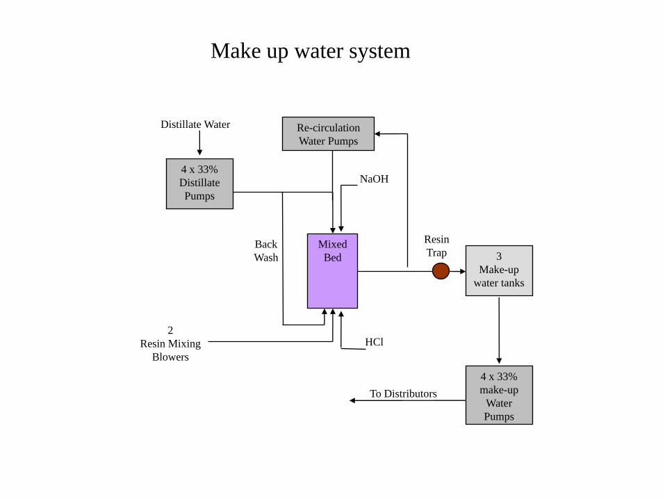
2
Resin Mixing
Blowers
To Distributors
Distillate Water
Back
Wash
HCl
Re-circulation
Water Pumps
NaOH
Mixed
Bed
4 x 33%
Distillate
Pumps
3
Make-up
water tanks
4 x 33%
make-up
Water
Pumps
Resin
Trap
Make up water system
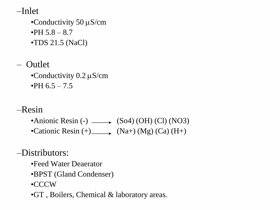
–Inlet
•Conductivity 50 S/cm
•PH 5.8 – 8.7
•TDS 21.5 (NaCl)
– Outlet
•Conductivity 0.2 S/cm
•PH 6.5 – 7.5
–Resin
•Anionic Resin (-) (So4) (OH) (Cl) (NO3)
•Cationic Resin (+) (Na+) (Mg) (Ca) (H+)
–Distributors:
•Feed Water Deaerator
•BPST (Gland Condenser)
•CCCW
•GT , Boilers, Chemical & laboratory areas.
• Mixed Bed Regeneration
– Back Washing
– Setting
– Caustic Soda & Hydrochloric Acid Injection
– Water Circuit
– Reagents Circuit
– Caustic Soda & Hydrochloric Acid Displacement
– Levelling
– Resin mixing
– Venting
– Final resin drain
– Final resin recirculation
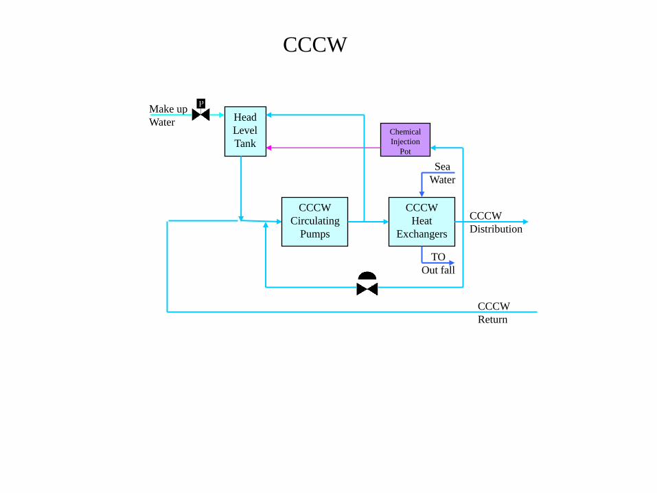
CCCW
Distribution
TO
Out fall
CCCW
Return
Make up
Water
Sea
Water
Head
Level
Tank
Chemical
Injection
Pot
CCCW
Circulating
Pumps
CCCW
Heat
Exchangers
CCCW

• Components:
• Two Head Level Tanks– To Compensate the Variations of the cooling water volume due to different thermal loads and ambient
temperature.
– To keep the pressure at the suction of the pumps constant.
• 2 Pneumatic On/Off Valves– Normally open
– To control the head tanks level.
– To restore any water loss in the tanks.
– To supply DM water when a new user is placed into service after maintenance.
• (3 x 50 %) CCCW Pumps.– Two in Duty, one stand by.
• (3 x 50 %) CCCW Heat Exchangers.– Two CCCW heat exchangers in duty, one stand by
• 2 Pneumatic Control Valves.– One is operating and one is stand by.
– To re-circulate CCCW water back to the pumps suction headers.
– (Differential Pressure across CCCW circuit users)
– ΔP is kept constant even if some users are out of service.
– To ensure constant water flow to the users.
• Two Chemical Injection Pots– Corrosion inhibitors
– Manually filled.
– The flow from the pots to the tanks due to ΔP.
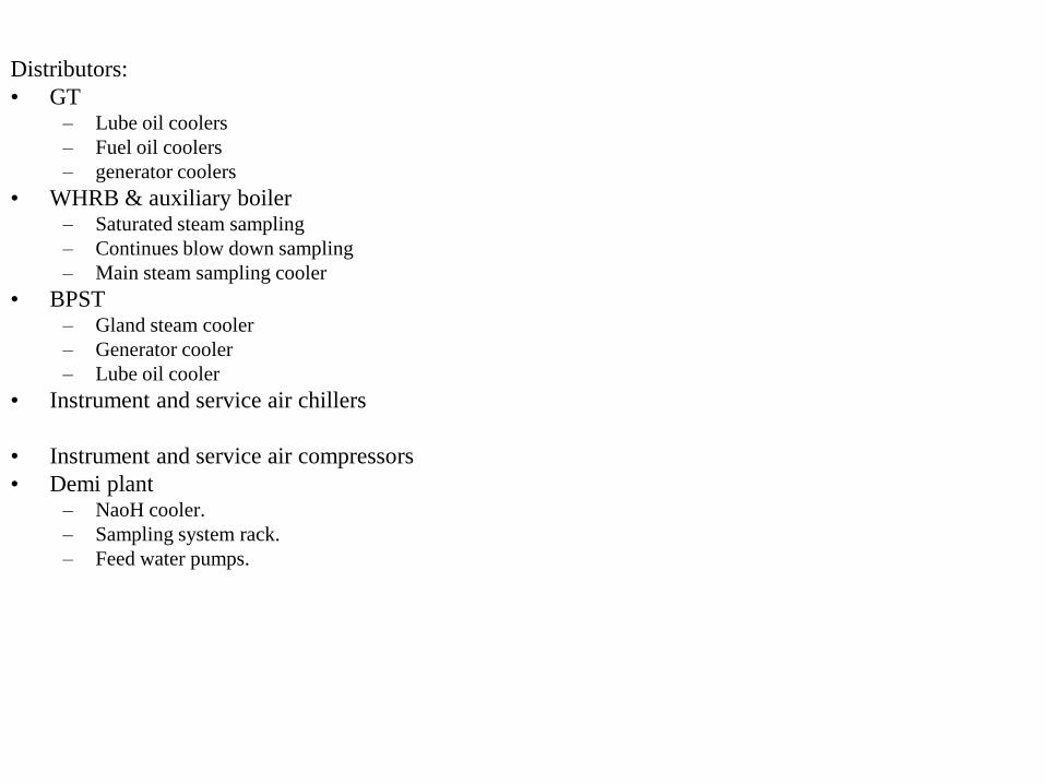
Distributors:
• GT– Lube oil coolers
– Fuel oil coolers
– generator coolers
• WHRB & auxiliary boiler– Saturated steam sampling
– Continues blow down sampling
– Main steam sampling cooler
• BPST– Gland steam cooler
– Generator cooler
– Lube oil cooler
• Instrument and service air chillers
• Instrument and service air compressors
• Demi plant– NaoH cooler.
– Sampling system rack.
– Feed water pumps.
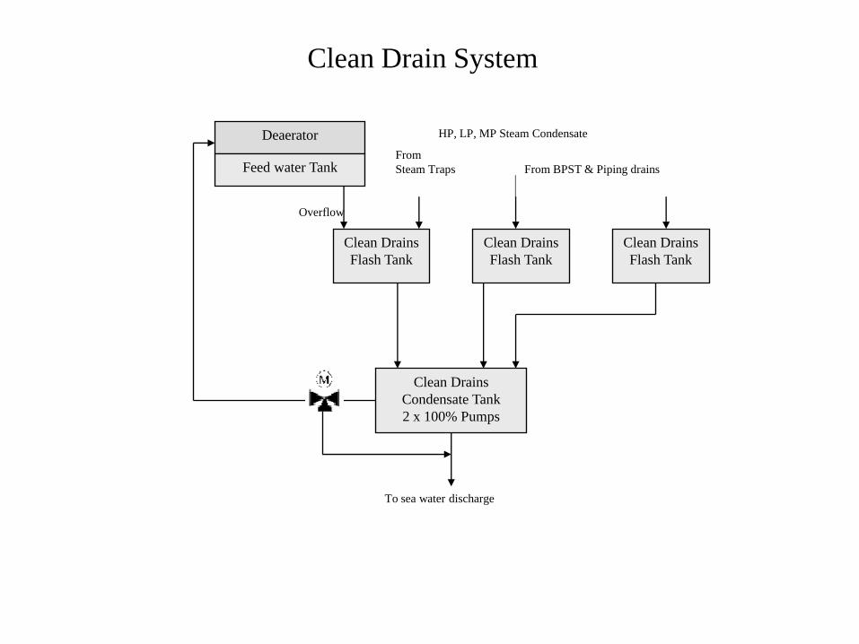
To sea water discharge
Overflow
Clean Drains
Flash Tank
Clean Drains
Flash Tank
Clean Drains
Flash Tank
Clean Drains
Condensate Tank
2 x 100% Pumps
Deaerator
Feed water Tank From
Steam Traps
HP, LP, MP Steam Condensate
From BPST & Piping drains
Clean Drain System
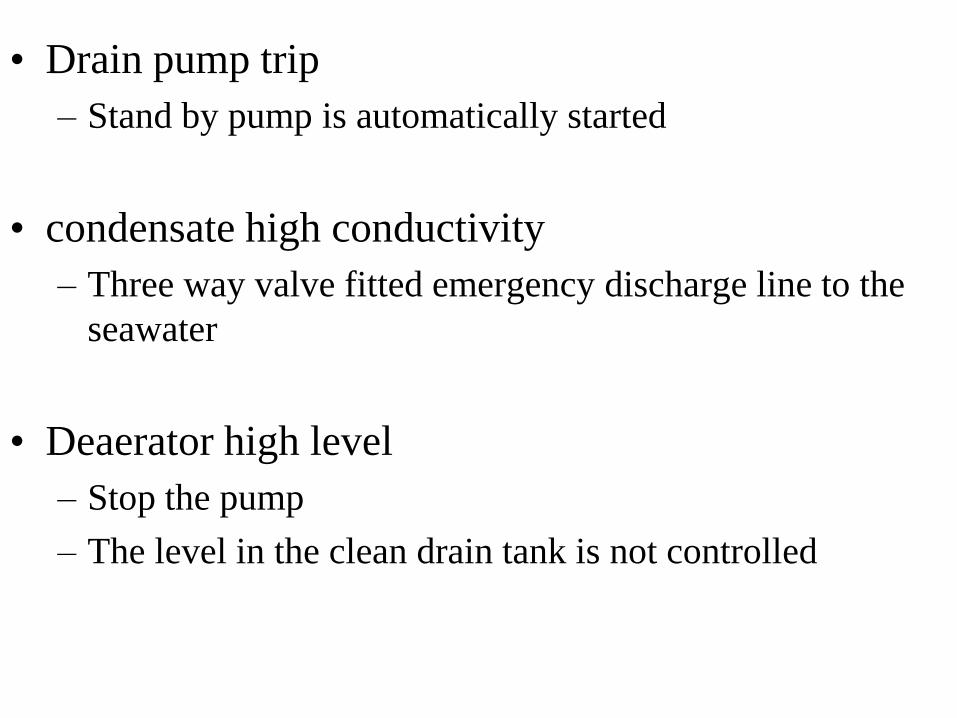
• Drain pump trip
– Stand by pump is automatically started
• condensate high conductivity
– Three way valve fitted emergency discharge line to the
seawater
• Deaerator high level
– Stop the pump
– The level in the clean drain tank is not controlled
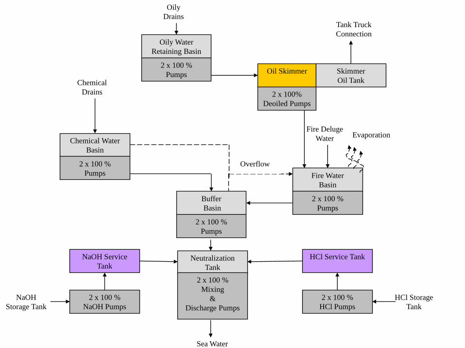
Sea Water
Evaporation
Tank Truck
Connection
Chemical
Drains
Chemical Water
Basin
2 x 100 %
Pumps
Buffer
Basin
2 x 100 %
Pumps
Neutralization
Tank
2 x 100 %
Mixing
&
Discharge Pumps
Fire Water
Basin
2 x 100 %
Pumps
HCl Service Tank
2 x 100 %
HCl Pumps
NaOH Service
Tank
2 x 100 %
NaOH Pumps
Fire Deluge
Water
Overflow
HCl Storage
Tank
NaOH
Storage Tank
Oily
Drains
Oily Water
Retaining Basin
2 x 100 %
Pumps Oil Skimmer Skimmer
Oil Tank
2 x 100%
Deoiled Pumps
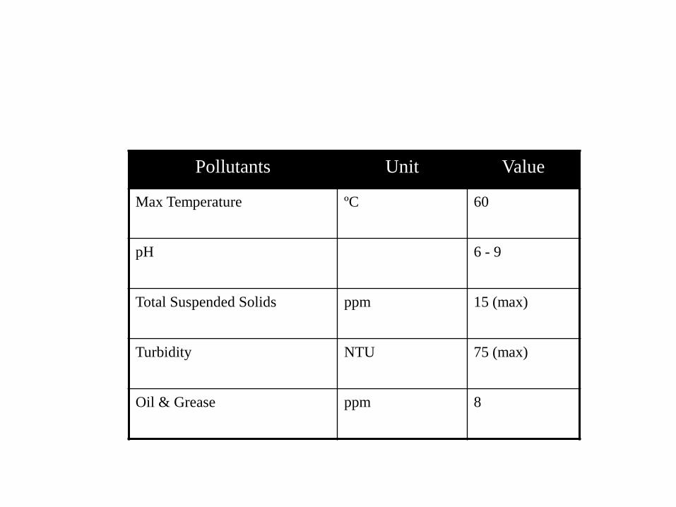
Pollutants Unit Value
Max Temperature ºC 60
pH 6 - 9
Total Suspended Solids ppm 15 (max)
Turbidity NTU 75 (max)
Oil & Grease ppm 8
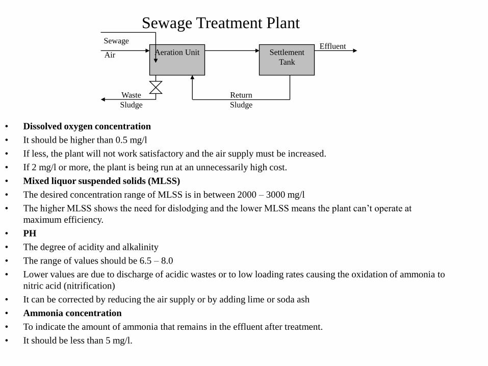
Effluent
Return
Sludge
Waste
Sludge
Sewage
Air Aeration Unit Settlement
Tank
Sewage Treatment Plant
• Dissolved oxygen concentration
• It should be higher than 0.5 mg/l
• If less, the plant will not work satisfactory and the air supply must be increased.
• If 2 mg/l or more, the plant is being run at an unnecessarily high cost.
• Mixed liquor suspended solids (MLSS)
• The desired concentration range of MLSS is in between 2000 – 3000 mg/l
• The higher MLSS shows the need for dislodging and the lower MLSS means the plant can’t operate at
maximum efficiency.
• PH
• The degree of acidity and alkalinity
• The range of values should be 6.5 – 8.0
• Lower values are due to discharge of acidic wastes or to low loading rates causing the oxidation of ammonia to
nitric acid (nitrification)
• It can be corrected by reducing the air supply or by adding lime or soda ash
• Ammonia concentration
• To indicate the amount of ammonia that remains in the effluent after treatment.
• It should be less than 5 mg/l.
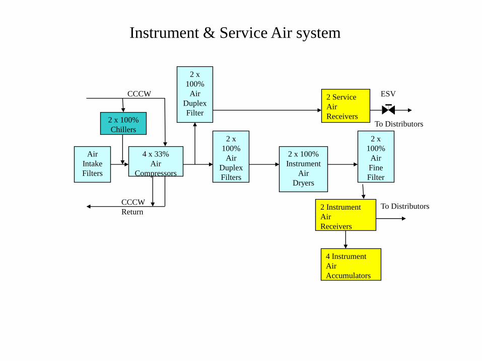
To Distributors
To DistributorsCCCW
Return
CCCW
4 x 33%
Air
Compressors
2 x
100%
Air
Duplex
Filters
2 x 100%
Instrument
Air
Dryers
2 x
100%
Air
Duplex
Filter
2 x
100%
Air
Fine
Filter
2 Instrument
Air
Receivers
2 Service
Air
Receivers 2 x 100%
Chillers
ESV
Air
Intake
Filters
4 Instrument
Air
Accumulators
Instrument & Service Air system
• Very low instrument air:– Emergency shut-off valve closes (at the service air discharge header)
– Pressure at the high limit opens the emergency shut-off valve.
• Start up
– Pre-condition (1 air dryer + 1 air chiller + 2 compressors not in malfunction & all measurements not in fault condition)
– Sequence start up• Start command for each compressor in sequence
• Get the feed back signals from each compressor.
• Get the pressure reading normal (2 o 3)
• Shut down sequence– Pre-condition
• Start up sequence completed
• Plant shutdown request
– Shut down sequence start up • Stop command to all compressors
• Get the feed back signals.
• Dew point analyser (– 20 ºC) dew point
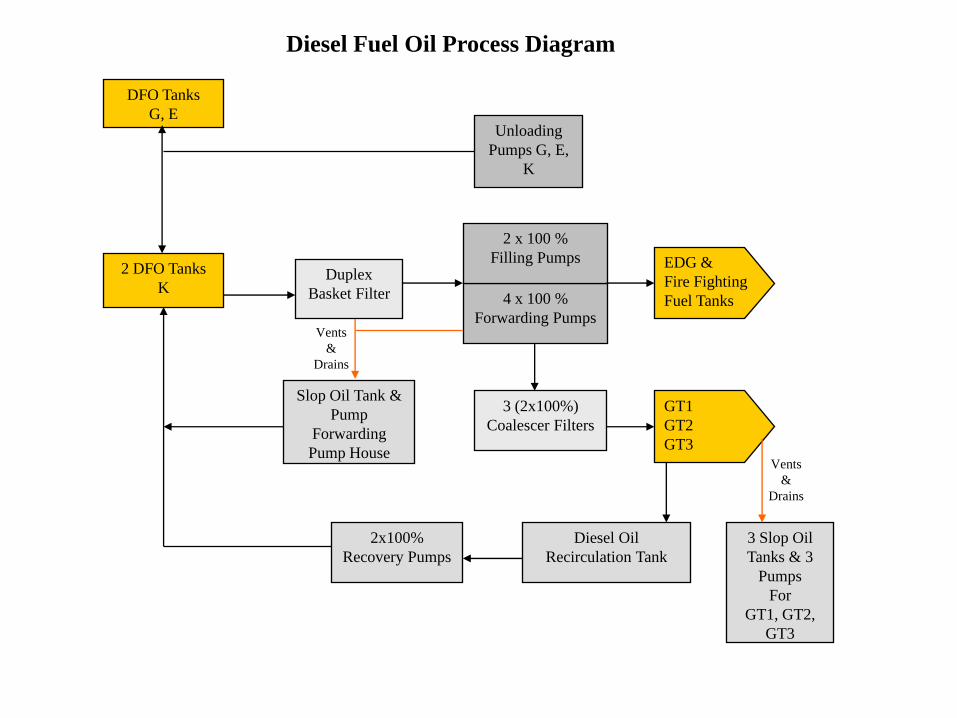
Vents
&
Drains
Vents
&
Drains
2 DFO Tanks
KDuplex
Basket Filter 4 x 100 %
Forwarding Pumps
2 x 100 %
Filling Pumps EDG &
Fire Fighting
Fuel Tanks
3 (2x100%)
Coalescer Filters
GT1
GT2
GT3
Diesel Oil
Recirculation Tank
2x100%
Recovery Pumps
3 Slop Oil
Tanks & 3
Pumps
For
GT1, GT2,
GT3
Slop Oil Tank &
Pump
Forwarding
Pump House
Unloading
Pumps G, E,
K
DFO Tanks
G, E
Diesel Fuel Oil Process Diagram

• Normal operation
• Active mode– Consumption of fuel in the GT
– GT isolation valve will open when the pressure is at least 4 bar
– When 1 isolation valve opens 1 pump will start ( 2 for 2 & 3 for 3)
• Passive mode– One filling pump will be in operation ( one stand by)
– To maintain the system under pressure at the conditions required by GT fuel system (GT is in fuel gas).
– To make up the loss in the system and to fill the day tanks of EDG & fire fighting motor pumps.
– The filling pump is independent of the redundant pressure transmitter (EDG & fire fighting)
• Test mode– All three isolation valves should be closed
– Start and stop the pumps manually.
Transient Operation
• Start up & shut down of the system
• Incidents
• Low gas pressure– Auto change over
• Low fuel oil pressure– Fuel oil pressure in the system
– Diesel filling pump starts by the redundant pressure transmitters (GT inlet)
– If the fuel oil pressure falls below the set low pressure, the stand by pump shall be actuated.
• Fire– GT on fire
• ESD valve closed
• All forwarding pumps stopped
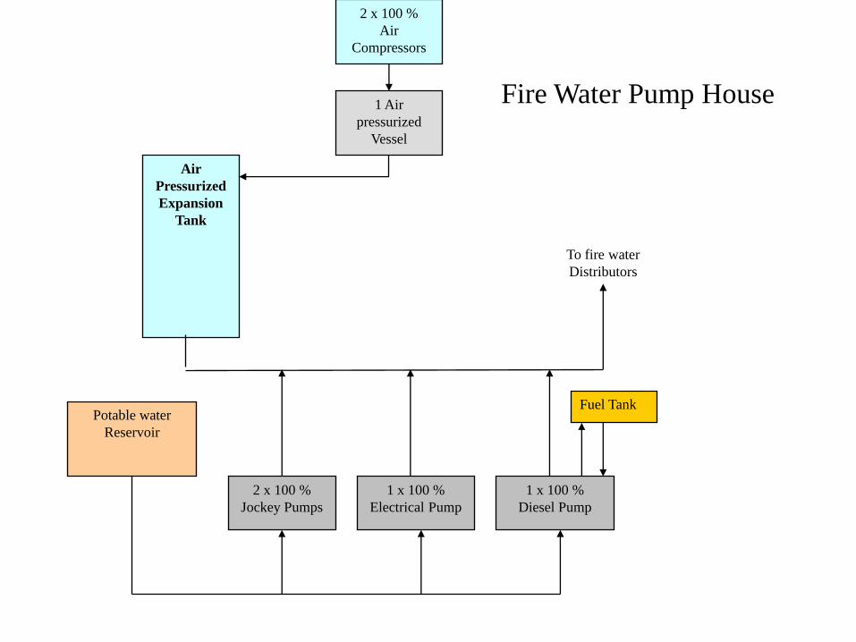
To fire water
Distributors
Potable water
Reservoir
2 x 100 %
Jockey Pumps
1 x 100 %
Electrical Pump
1 x 100 %
Diesel Pump
2 x 100 %
Air
Compressors
1 Air
pressurized
Vessel
Air
Pressurized
Expansion
Tank
Fuel Tank
Fire Water Pump House
A common suction line feeds the system from the firewater storage tanks
To supply water to
• Underground hydrant main supply line
• Indoor and outdoor water hydrants
• Water spray systems
• Water sprinkler systems
• Main components:
• 1 electric driven fire pump
• 1 diesel engine fire pump
• 2 Jockey pumps
– One on duty & one stand bye
– To maintain the water amount and pressure in the main supply line.
– The jockey pump and the air compressor will stop automatically after the normal conditions have been reached or when one of the main pumps is operated.
• 1 pressurized expansion tank with connected air compressor– To maintain the system pressure at 9.8 bar
– Air compressor 10 bar
– 3 Level float switches (H & L 60 mm, HH & LL 120 mm)
– (Stop jockey pump at H level, report at HH)
– (Start jockey pump at L level, report at LL)
• During shut down periods of the water can be supplied from G station main or stand by fire fighting pump.
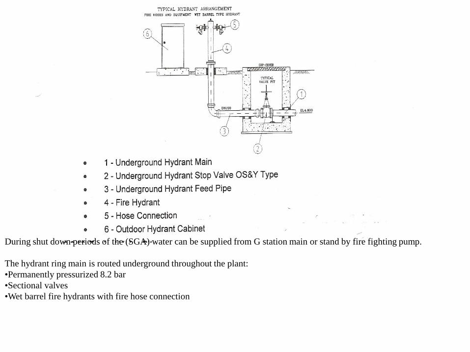
During shut down periods of the (SGA) water can be supplied from G station main or stand by fire fighting pump.
The hydrant ring main is routed underground throughout the plant:
•Permanently pressurized 8.2 bar
•Sectional valves
•Wet barrel fire hydrants with fire hose connection
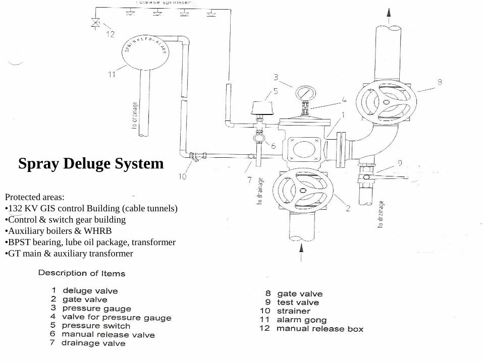
Protected areas:
•132 KV GIS control Building (cable tunnels)
•Control & switch gear building
•Auxiliary boilers & WHRB
•BPST bearing, lube oil package, transformer
•GT main & auxiliary transformer
Spray Deluge System
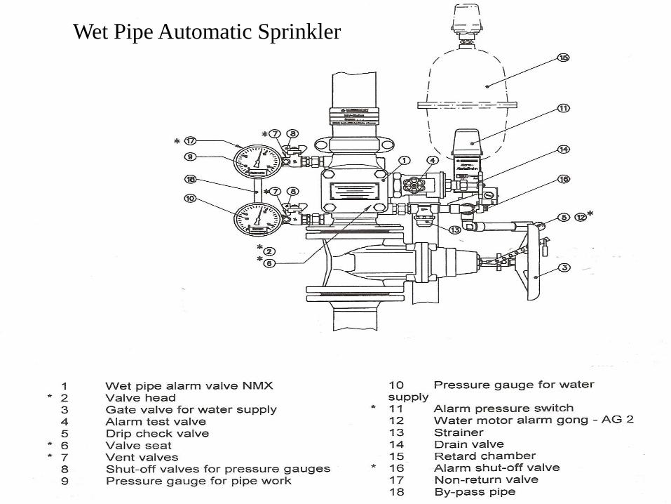
Wet Pipe Automatic Sprinkler
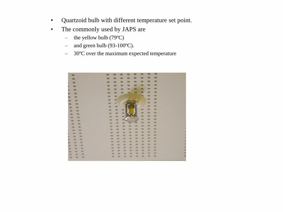
• Quartzoid bulb with different temperature set point.
• The commonly used by JAPS are
– the yellow bulb (79ºC)
– and green bulb (93-100ºC).
– 30ºC over the maximum expected temperature
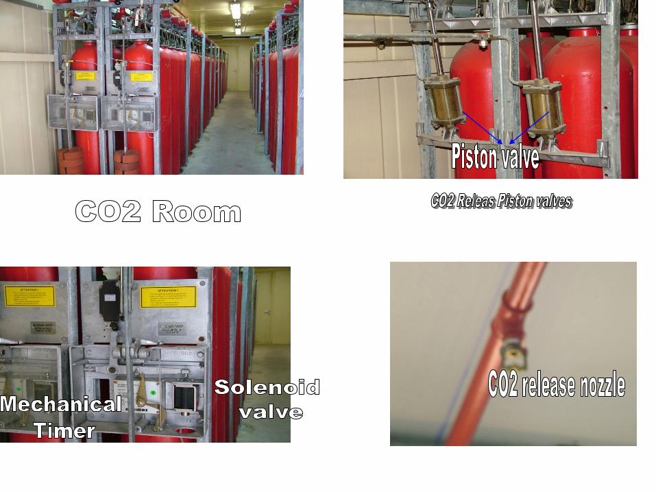
CO2 Fire Fighting System:
The system uses carbon dioxide as the extinguishing agent.
•The CO2 is chemically neutral, color & odorless gas, electrically non conductive, it leaves no residues and it is non-corroding.
•It suffocates the fire by decreasing the oxygen content of the air to at least 15 VOL%.
•The CO2 penetrates the flooding area (switch gear, cable, relay & battery rooms) rapidly and evenly.
•There are multi area CO2 system, which consists essentially of an appropriate number of CO2 cylinders arranged in groups in
racks (where CO2 is pressurized into liquid) calculated for the largest space to be protected, the necessary valves and a
permanently laid network of piping with discharge nozzles suitable to be distributed to the desired location.
•Multi area systems are provided with an installed 100% spare CO2 capacity.
The evacuation time (retardation of release) is done once by an electrical delay time (1 to 255 sec) usually less then 60 sec,
and twice with a mechanical delay time in the release box (1 to 30 sec).
The CO2 release can be stop during the electrical time delay by hold push button.

•Foam forms a coherent flouting blanket on flammable and combustible liquids lighter than water.
•it extinguishes fire by air injection into the foam solution.
•The protected areas are: auxiliary boiler burner plant, fuel oil tank.
•A wet, heavy fire fighting foam is obtained by adding a low percentage of air to a foam & water mixture.
•foam classified as follows:
•Low expansion foam: at rate of 1: 5 to1: 7, raped spreading, used in burning liquids, gas line, oils
•Medium expansion foam: at rate of 1: 40 to 1: 150, fluid and intensive to heat, used in ground level, store rooms
•High expansion foam: up to 1: 1000, dry, very light, used in large rooms, production halls.
Foam system
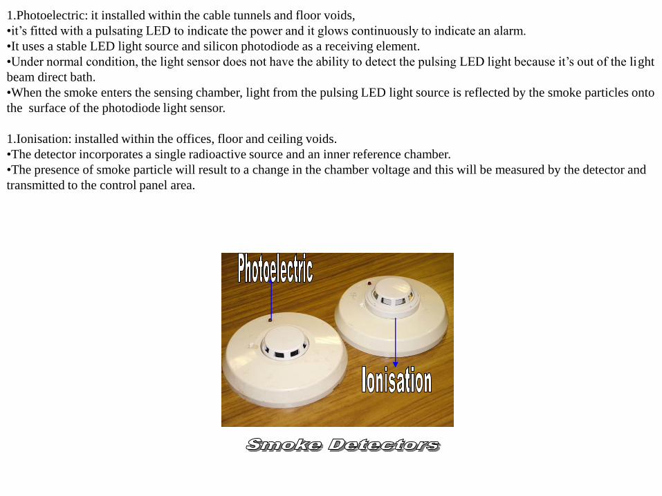
1.Photoelectric: it installed within the cable tunnels and floor voids,
•it’s fitted with a pulsating LED to indicate the power and it glows continuously to indicate an alarm.
•It uses a stable LED light source and silicon photodiode as a receiving element.
•Under normal condition, the light sensor does not have the ability to detect the pulsing LED light because it’s out of the light
beam direct bath.
•When the smoke enters the sensing chamber, light from the pulsing LED light source is reflected by the smoke particles onto
the surface of the photodiode light sensor.
1.Ionisation: installed within the offices, floor and ceiling voids.
•The detector incorporates a single radioactive source and an inner reference chamber.
•The presence of smoke particle will result to a change in the chamber voltage and this will be measured by the detector and
transmitted to the control panel area.

Heat detectors:
•They are installed in turbine enclosure, cable tunnels, and kitchens.
•Heat detector is a combination rate of Rise/ Fixed temperature sensor.
•The rate of rise operation is selectable in either (8.3ºC, 11.1ºC) / min.
•Fixed temperature is selectable for 47.2ºC, 57.2ºC alarm initiation.

Linear Heat Detector:
• (Protect wire linear heat detector)
• The main component is the proprietary cable that detects heat conditions any where along its length.
• The sensor cable is comprised of two steel conductors individually insulated with a heat sensitive polymer.
• The insulated conductors are twisted together to impose a spring pressure between them, then wrapped with a protective tape and finished with an outer jacket suitable for the environment in which the detector will be installed
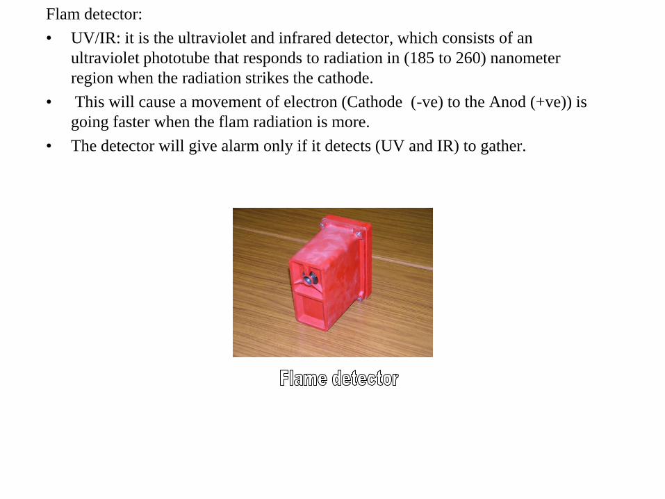
Flam detector:
• UV/IR: it is the ultraviolet and infrared detector, which consists of an
ultraviolet phototube that responds to radiation in (185 to 260) nanometer
region when the radiation strikes the cathode.
• This will cause a movement of electron (Cathode (-ve) to the Anod (+ve)) is
going faster when the flam radiation is more.
• The detector will give alarm only if it detects (UV and IR) to gather.
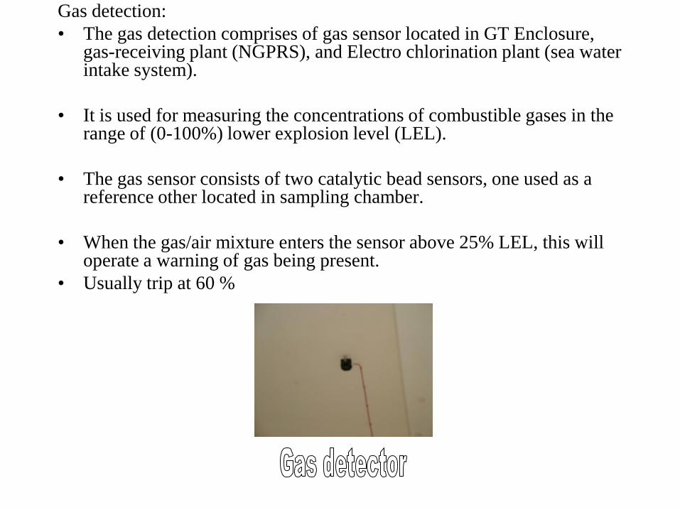
Gas detection:
• The gas detection comprises of gas sensor located in GT Enclosure, gas-receiving plant (NGPRS), and Electro chlorination plant (sea water intake system).
• It is used for measuring the concentrations of combustible gases in the range of (0-100%) lower explosion level (LEL).
• The gas sensor consists of two catalytic bead sensors, one used as a reference other located in sampling chamber.
• When the gas/air mixture enters the sensor above 25% LEL, this will operate a warning of gas being present.
• Usually trip at 60 %
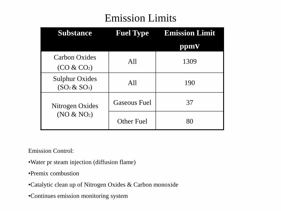
Emission Limits
Substance Fuel Type Emission Limit
ppmv
Carbon Oxides
(CO & CO2)All 1309
Sulphur Oxides
(SO2 & SO3)All 190
Nitrogen Oxides
(NO & NO2)
Gaseous Fuel 37
Other Fuel 80
Emission Control:
•Water pr steam injection (diffusion flame)
•Premix combustion
•Catalytic clean up of Nitrogen Oxides & Carbon monoxide
•Continues emission monitoring system
Underground Services
• Sea Water & Product Distillate.
• Potable & Service Water.
• Fire Fighting.
• Oil Drainage.
• Chemical Drainage.
• Sewage & Irrigation.
• Fuel Lines.
• Earthing System.
• Electrical Cables.
• Etisalat Cables.
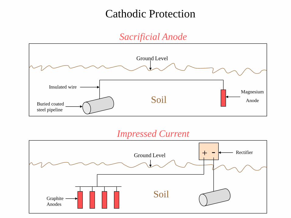
Cathodic Protection
Magnesium
AnodeBuried coated
steel pipeline
Insulated wire
Soil
+ -
SoilGraphite
Anodes
Rectifier
Ground Level
Ground Level
Impressed Current
Sacrificial Anode