Embed Size (px)
Citation preview
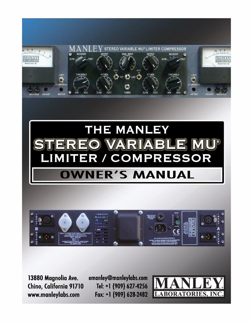
MANLEY LABORATORIES, INC.
MANLEY STEREO VARIABLE MU® LIMITER COMPRESSOR
OWNER’S MANUAL
TUBES RULE brought to you by the clever folks at:
MANLEY LABORATORIES, INC. 13880 MAGNOLIA AVE. CHINO, CA. 91710 USA
TEL: (909) 627-4256 FAX: (909) 628-2482
email: [email protected]
website: www.manley.com
OWNERʼS MANUAL
THE MANLEY
LIMITER / COMPRESSORSTEREO VARIABLE MU®
13880 Magnolia Ave.Chino, California 91710www.manleylabs.com
[email protected]: +1 (909) 627-4256
Fax: +1 (909) 628-2482
CONTENTS
SECTION PAGE
INTRODUCTION 3
MAINS CONNECTIONS 4
INSTALLATION 5
FRONT PANEL 6
REAR PANEL 7
EXAMPLE SETTINGS 8
FRONT PANEL ADJUSTMENTS 9
OPERATIONAL NOTES 10
MASTERING AND M/S MODELS 11
T-BAR MODIFICATION 12
GAIN REDUCTION CURVES 13
SPECIFICATIONS 14
TECHNICAL NOTES 15
SERVICE ADJUSTMENTS 16
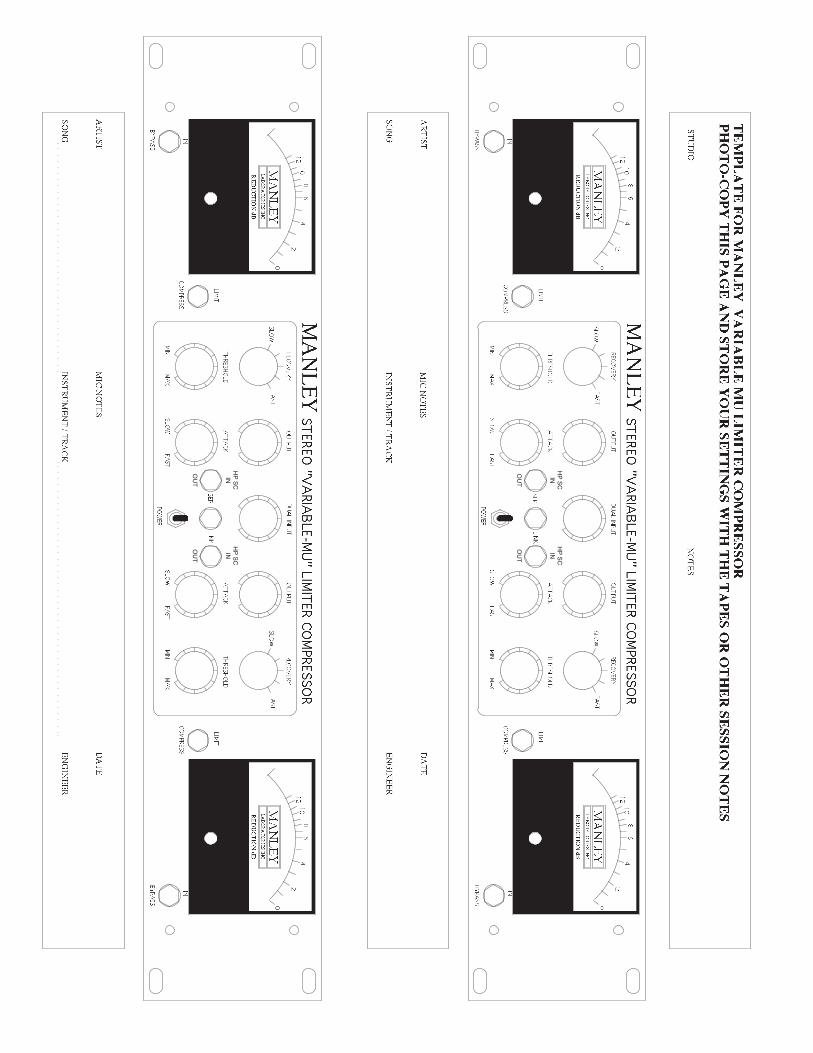
BLANK TEMPLATE TO STORE SETTINGS 17
CDrev5.11.11
INTRODUCTION THANK YOU!... for choosing the Manley Laboratories Stereo Variable Mu® Limiter Compressor. this unit has been our best selling product for many years. It is one of the very few compressors that has be-come a real standard in Mastering studios and contributed to most hit records over the last decade and probably the next. “Mu” is tube-speak for gain, and Variable Mu® is our registered trademark for this limiter compressor. It works by using the “remote cut-off” or re-biasing of a vacuum tube to achieve compression. The precious vintage Fairchild 670 also uses this technique and is one of few all-tube compressor to do so, that we know of. Even the side-chain has glowing rectifier bottles. How’s it work? The unique 5670 dual triode is at the center of the peak-reducing and compression action constantly being re-biased by the vacuum tube rectified side-chain control voltages which cause this tube to smoothly change its gain. Just like that.
LOCATION & VENTILATION The Manley Stereo Variable Mu® Limiter Compressor must be installed in a stable loca-tion with ample ventilation. It is recommended, if this unit is rack mounted, that you allow enough clearance on the top and bottom of the unit such that constant movement of air can flow through the ventilation holes. There are 8 tubes inside this unit so it does run quite hot. Good ventilation is definitely encouraged.
UNPACKING: Unpack the unit carefully by removing all the custom foam packing material and make sure that all supplied accessories are present. Carefully examine all items for any pos-sibility of shipping damage. All of the tubes are already installed and should have survived the journey from our factory to your studio. They should be standing at attention in their sockets, and should show no signs of distress such as chipped glass, loose internal components or obvi-ous breakage. If the unit is damaged or fails to operate, notify the shipper or your dealer or us or your local authorities immediately. Or if you suspect The Shipping People threw it off the air-plane and onto your front porch whilst flying overhead at 30,000 feet, notify the shipping com-pany without delay and complain to them as we only guarantee this unit to be able to survive a drop of 23,487 feet or less.
Your Manley Variable Mu® Limiter Compressor was packed with extreme love and care, and each box includes the following components and accessories:a) 1 each, 6 foot IEC 3-conductor power cable b) 1 each, Owner’s Manual (that we hope you will keep reading.)
It is prudent to retain the shipping materials for future use, as they are custom-formed for this unit and will greatly minimize the chance of shipping-related damage should you ever need to put your precious Variable Mu®in the careless hands of The Shipping People again. We have heard that certain rodents might enjoy munching on the packing foam. We are sorry to report that we do not warranty the packing foam against attack by mice, rats, or other hungry critters, hungry chil-dren, hungry neighbors, etc. Try glue traps or spring-traps loaded with peanut butter to eliminate these unwelcome freeloaders from your property.
3
4
MAINS CONNECTIONS
Your VARIABLE MU has been factory set to the correct mains voltage for your country. The voltage setting is marked on the serial badge, located on the rear panel. Check that this complies with your local supply. Exportunitsforcertainmarketshaveamouldedmainsplugfittedtocomplywithlocalrequirements.Ifyourunitdoesnothaveaplugfittedthecolouredwiresshouldbeconnectedtotheappropriateplugterminalsinaccordancewith the following code:
GREEN/YELLOW EARTHBLUE NEUTRALBROWN LIVE
As the colours of the wires in the mains lead may not correspond with the coloured marking identifying the termi-nals in your plug proceed as follows:
The wire which is coloured GREEN/YELLOW must be connected to the terminal in the plug which is marked by the letter E or by the safety earth symbol or coloured GREEN or GREEN and YELLOW.
The wire which is coloured BLUE must be connected to the terminal in the plug which is marked by the letter N or coloured BLACK.
The wire which is coloured BROWN must be connected to the terminal in the plug which is marked by the letter L or coloured RED.
DO NOT CONNECT/SWITCH ON THE MAINS SUPPLY UNTIL ALL OTHER CONNECTIONS HAVE BEEN MADE.
Waste Electrical and Electronic Equipment (WEEE)
Information for customers:TheEuropeanParliamentandtheCounciloftheEuropeanUnionhaveissuedtheWasteElectricalandElectronicEquipmentDirective.ThepurposeoftheDirec-tiveisthepreventionofwasteofelectricalandelectronicequipment,andtopromotethereuseandrecyclingandotherformsofrecoveryofsuchwaste.Assuchthe Directive concerns producers, distributors and consumers.
TheWEEEdirectiverequiresthatbothmanufacturersandend-consumersdisposeofelectricalandelectronicequipmentandpartsinanenvironmentallysafeman-ner,andthatequipmentandwastearereusedorrecoveredfortheirmaterialsorenergy.Electricalandelectronicequipmentandpartsmustnotbedisposedofwithnormalhouseholdwastage;allelectricalandelectronicequipmentandpartsmustbecollectedanddisposedofseparately.
Productsandequipmentwhichmustbecollectedforreuse,recyclingandotherformsofrecoveryaremarkedwiththefollowingpictogram:
Smallproductsmaynotalwaysbemarkedwiththispictograminwhichcasethisispresentintheinstructionsforuse,ontheguaranteecertificateandprintedonthe packaging. Whendisposingofelectricalandelectronicequipmentbyuseofthecollectionsystemsavailableinyourcountry,youprotecttheenvironment,humanhealthandcontributetotheprudentandrationaluseofnaturalresources.Collectingelectricalandelectronicequipmentandwastepreventsthepotentialcontaminationofnaturewiththehazardoussubstanceswhichmaybepresentinelectricalandelectronicproductsandequipment.
Your MANLEY or LANGEVIN retailer will assist with and advise you of the correct way of disposal in your country.
INSTALLATION
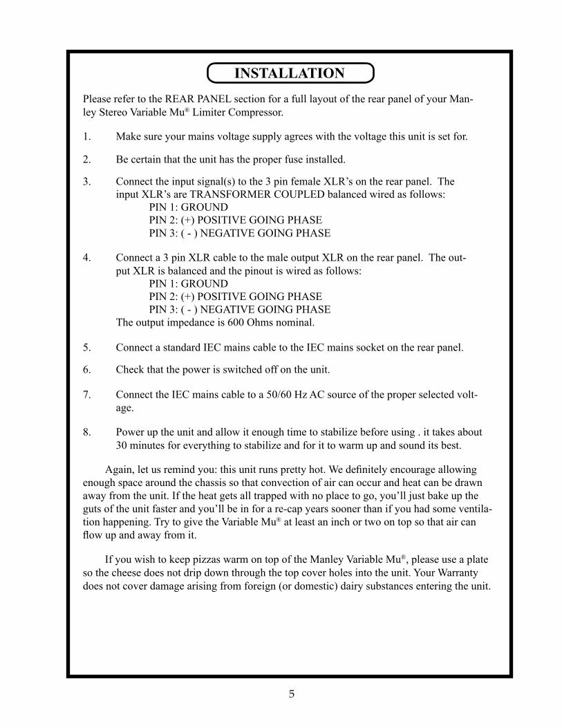
Please refer to the REAR PANEL section for a full layout of the rear panel of your Man-ley Stereo Variable Mu® Limiter Compressor.
1. Make sure your mains voltage supply agrees with the voltage this unit is set for.
2. Be certain that the unit has the proper fuse installed.
3. Connect the input signal(s) to the 3 pin female XLR’s on the rear panel. The input XLR’s are TRANSFORMER COUPLED balanced wired as follows:
PIN 1: GROUND PIN 2: (+) POSITIVE GOING PHASE PIN 3: ( - ) NEGATIVE GOING PHASE
4. Connect a 3 pin XLR cable to the male output XLR on the rear panel. The out-put XLR is balanced and the pinout is wired as follows:
PIN 1: GROUND PIN 2: (+) POSITIVE GOING PHASE PIN 3: ( - ) NEGATIVE GOING PHASE
The output impedance is 600 Ohms nominal.
5. Connect a standard IEC mains cable to the IEC mains socket on the rear panel.
6. Check that the power is switched off on the unit.
7. Connect the IEC mains cable to a 50/60 Hz AC source of the proper selected volt-age.
8. Power up the unit and allow it enough time to stabilize before using . it takes about 30 minutes for everything to stabilize and for it to warm up and sound its best.
Again, let us remind you: this unit runs pretty hot. We definitely encourage allowing enough space around the chassis so that convection of air can occur and heat can be drawn away from the unit. If the heat gets all trapped with no place to go, you’ll just bake up the guts of the unit faster and you’ll be in for a re-cap years sooner than if you had some ventila-tion happening. Try to give the Variable Mu® at least an inch or two on top so that air can flow up and away from it.
If you wish to keep pizzas warm on top of the Manley Variable Mu®, please use a plate so the cheese does not drip down through the top cover holes into the unit. Your Warranty does not cover damage arising from foreign (or domestic) dairy substances entering the unit.
5
A H B D F
C
I
G E
F
C
D B H A
E
J J
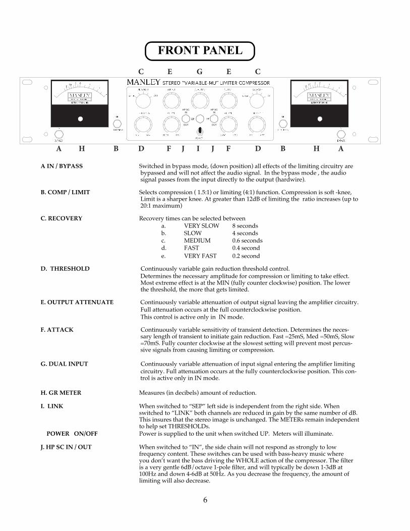
FRONT PANEL
A IN / BYPASS Switched in bypass mode, (down position) all effects of the limiting circuitry are bypassed and will not affect the audio signal. In the bypass mode , the audio signal passes from the input directly to the output (hardwire).
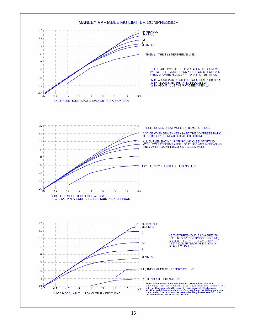
B. COMP / LIMIT Selects compression ( 1.5:1) or limiting (4:1) function. Compression is soft -knee, Limit is a sharper knee. At greater than 12dB of limiting the ratio increases (up to 20:1 maximum)
C. RECOVERY Recovery times can be selected between a. VERY SLOW 8 seconds b. SLOW 4 seconds c. MEDIUM 0.6 seconds d. FAST 0.4 second e. VERY FAST 0.2 second
D. THRESHOLD Continuously variable gain reduction threshold control. Determines the necessary amplitude for compression or limiting to take effect. Most extreme effect is at the MIN (fully counter clockwise) position. The lower the threshold, the more that gets limited.
E. OUTPUT ATTENUATE Continuously variable attenuation of output signal leaving the amplifier circuitry. Full attenuation occurs at the full counterclockwise position. This control is active only in IN mode.
F. ATTACK Continuously variable sensitivity of transient detection. Determines the neces-sary length of transient to initiate gain reduction. Fast =25mS, Med =50mS, Slow =70mS. Fully counter clockwise at the slowest setting will prevent most percus-sive signals from causing limiting or compression.
G. DUAL INPUT Continuously variable attenuation of input signal entering the amplifier limiting circuitry. Full attenuation occurs at the fully counterclockwise position. This con-
trol is active only in IN mode.
H. GR METER Measures (in decibels) amount of reduction.
I. LINK When switched to “SEP” left side is independent from the right side. When switched to “LINK” both channels are reduced in gain by the same number of dB. This insures that the stereo image is unchanged. The METERs remain independent to help set THRESHOLDs. POWER ON/OFF Power is supplied to the unit when switched UP. Meters will illuminate.
J. HP SC IN / OUT When switched to “IN”, the side chain will not respond as strongly to low frequency content. These switches can be used with bass-heavy music where you don’t want the bass driving the WHOLE action of the compressor. The filter is a very gentle 6dB/octave 1-pole filter, and will typically be down 1-3dB at 100Hz and down 4-6dB at 50Hz. As you decrease the frequency, the amount of limiting will also decrease.
6
12AL5
GAINTRIM
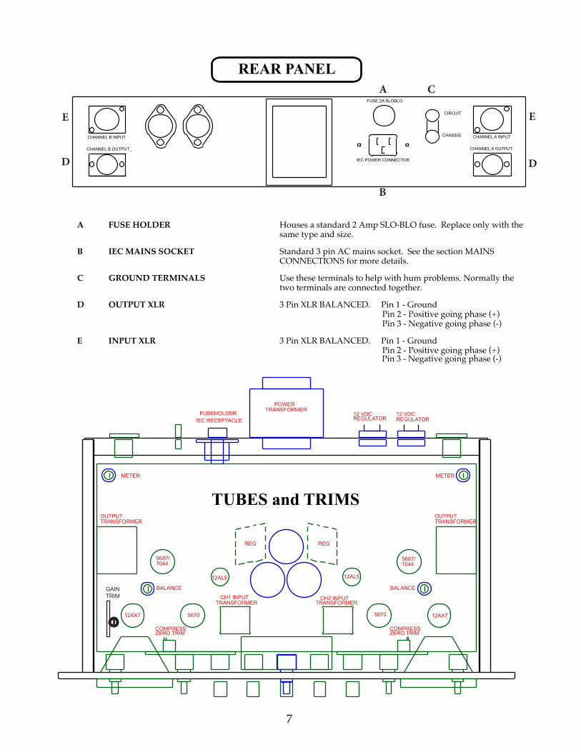
REAR PANEL
CHANNEL B INPUT
CHANNEL B OUTPUT
FUSE 2A SLOBLO
IEC POWER CONNECTOR
CIRCUIT
CHASSIS CHANNEL A INPUT
CHANNEL A OUTPUT
FUSEHOLDER IEC RECEPTACLE
POWER TRANSFORMER
Pin 3 - Negative going phase (-)
12 VDC REGULATOR
12 VDC REGULATOR
METER METER
OUTPUT TRANSFORMER
12AX7
5687/7044
TUBES and TRIMS
REG REG
12AL5
BALANCE BALANCE
5670
COMPRESS ZERO TRIM
CH1 INPUT TRANSFORMER
CH2 INPUT TRANSFORMER
5670
COMPRESS ZERO TRIM
OUTPUT TRANSFORMER
12AX7
A FUSE HOLDER Houses a standard 2 Amp SLO-BLO fuse. Replace only with the same type and size.
B IEC MAINS SOCKET Standard 3 pin AC mains socket. See the section MAINS CONNECTIONS for more details.
C GROUND TERMINALS Use these terminals to help with hum problems. Normally the two terminals are connected together.
D OUTPUT XLR 3 Pin XLR BALANCED. Pin 1 - Ground Pin 2 - Positive going phase (+) Pin 3 - Negative going phase (-)
E INPUT XLR 3 Pin XLR BALANCED. Pin 1 - Ground Pin 2 - Positive going phase (+)
7
A
B
C
D
E E
D
5687/7044
HP SCIN
OU
T
HP SCIN
OU
T
HP SCIN
OU
T
HP SCIN
OU
T
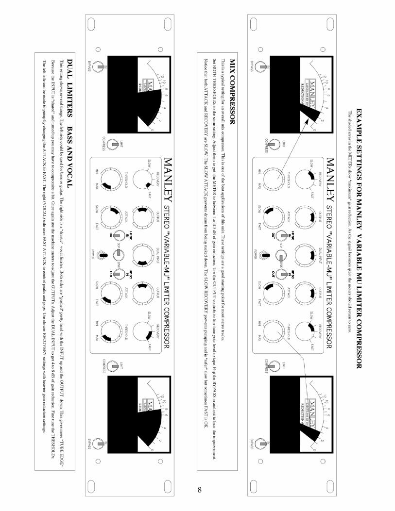
8
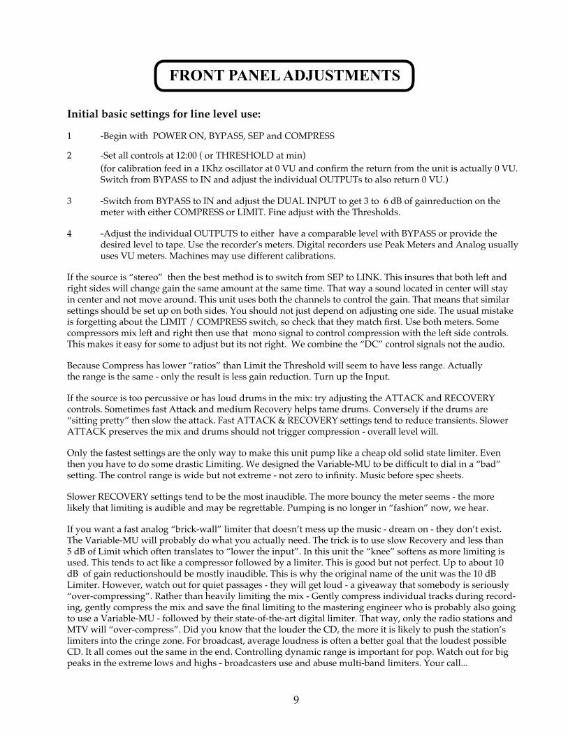
FRONT PANEL ADJUSTMENTS
Initial basic settings for line level use:
1 -Begin with POWER ON, BYPASS, SEP and COMPRESS
2 -Set all controls at 12:00 ( or THRESHOLD at min) (for calibration feed in a 1Khz oscillator at 0 VU and confirm the return from the unit is actually 0 VU. Switch from BYPASS to IN and adjust the individual OUTPUTs to also return 0 VU.)
3 -Switch from BYPASS to IN and adjust the DUAL INPUT to get 3 to 6 dB of gainreduction on the meter with either COMPRESS or LIMIT. Fine adjust with the Thresholds.
4 -Adjust the individual OUTPUTS to either have a comparable level with BYPASS or provide the desired level to tape. Use the recorder’s meters. Digital recorders use Peak Meters and Analog usually uses VU meters. Machines may use different calibrations.
If the source is “stereo” then the best method is to switch from SEP to LINK. This insures that both left and right sides will change gain the same amount at the same time. That way a sound located in center will stay in center and not move around. This unit uses both the channels to control the gain. That means that similar settings should be set up on both sides. You should not just depend on adjusting one side. The usual mistake is forgetting about the LIMIT / COMPRESS switch, so check that they match first. Use both meters. Some compressors mix left and right then use that mono signal to control compression with the left side controls. This makes it easy for some to adjust but its not right. We combine the “DC” control signals not the audio.
Because Compress has lower “ratios” than Limit the Threshold will seem to have less range. Actually the range is the same - only the result is less gain reduction. Turn up the Input.
If the source is too percussive or has loud drums in the mix: try adjusting the ATTACK and RECOVERY controls. Sometimes fast Attack and medium Recovery helps tame drums. Conversely if the drums are “sitting pretty” then slow the attack. Fast ATTACK & RECOVERY settings tend to reduce transients. Slower ATTACK preserves the mix and drums should not trigger compression - overall level will.
Only the fastest settings are the only way to make this unit pump like a cheap old solid state limiter. Even then you have to do some drastic Limiting. We designed the Variable-MU to be difficult to dial in a “bad” setting. The control range is wide but not extreme - not zero to infinity. Music before spec sheets.
Slower RECOVERY settings tend to be the most inaudible. The more bouncy the meter seems - the more likely that limiting is audible and may be regrettable. Pumping is no longer in “fashion” now, we hear.
If you want a fast analog “brick-wall” limiter that doesn’t mess up the music - dream on - they don’t exist. The Variable-MU will probably do what you actually need. The trick is to use slow Recovery and less than 5 dB of Limit which often translates to “lower the input”. In this unit the “knee” softens as more limiting is used. This tends to act like a compressor followed by a limiter. This is good but not perfect. Up to about 10 dB of gain reductionshould be mostly inaudible. This is why the original name of the unit was the 10 dB Limiter. However, watch out for quiet passages - they will get loud - a giveaway that somebody is seriously “over-compressing”. Rather than heavily limiting the mix - Gently compress individual tracks during record-ing, gently compress the mix and save the final limiting to the mastering engineer who is probably also going to use a Variable-MU - followed by their state-of-the-art digital limiter. That way, only the radio stations and MTV will “over-compress”. Did you know that the louder the CD, the more it is likely to push the station’s limiters into the cringe zone. For broadcast, average loudness is often a better goal that the loudest possible CD. It all comes out the same in the end. Controlling dynamic range is important for pop. Watch out for big peaks in the extreme lows and highs - broadcasters use and abuse multi-band limiters. Your call...
9
OPERATION NOTES
The “MANLEY STEREO VARIABLE MU LIMITER - COMPRESSOR” is designed for multiple pur-poses. The unit can be used stereo or as 2 individual channels of limiting or compression. It can be used as a balanced line amp capable of 24 db! of gain and as a pre-amp for low level signals. . With higher input gain settings the unit can be used to create gentle tube distortion if desired. Modest settings will often enhance the signal in ways difficult to describe however the range includes “tube warmth”, richness and enhanced clarity and magic. We know several famous producers and engineers that record every possible track, and the mix and then master through these LIMITER-COMPRESSORS.
The attack and recovery controls are important to understand. The response to transients and percus-sive sounds are affected by the attack control. Recovery is the time it takes for the gain to return to normal or zero reduction. This is called “RELEASE” on some limiters.
We can use a typical mix with dynamic vocals, drums and bass for an example. With this example a fast attack setting will react to the drums and reduce the overall gain. If the recovery is very fast then the gain will return to normal quickly. This will have an audible effect of reducing some of the level and attack of the drums in the mix. As the recovery is set slower the gain changes that the drums cause might be heard as “pumping”. Now these gain changes caused by the drums are pulling down vocals, some bass and caus-ing volume changes. Slower recovery settings will usually keep the gain changes more inaudible but will also lower the perceived volume. A slow attack setting will tend to ignore drums and other fast signals but will react to the vocals and bass in our example. A slow attack might also let a hard kick drum transient distort the next piece of equipment in the chain. We have set up the unit so that medium settings of both controls pro-vide good gain control and little change in mix values.
LIMITING OR COMPRESSION Two basic rules of thumb with any compressor or limiter should be reminded. Typical amounts of gain reduction shown by GR meter should be 2 to 6 dB. The more that the needle swings the more likely the gain changes will be audible. Listen for objectionable “pumping” with fast set-tings. Use your ears to determine optimum settings more than the meters. Some limiters add unpleasant artifacts with any reasonable looking setting. This limiter may give some magic at unexpected settings. It may help to use the bypass switch to compare the original input with the processed output to verify that an improvement is real. Then, because the peaks are reduced, the final output can be adjusted a little louder than the input. It should be borne in mind that the intended usage, and function therefore, is very different between limiting and compression. In limiting mode we are seeking to control PEAK overshoots or the ‘ceiling’ level as inaudibly as possible, normally in the 2 to4 dB area. By using compression we seek to “fold in” a ratio of, say, 20 or more into 10 dB. Both limiting and compression can produce the effect of increasing the average levels and background noise - depending on the degree or amount of limiting / compression used. Because dynamic range and peaks can be reduced, often overall loudness can be increased at the output. This is called GAIN MAKE-UP on some compressors and is simply the OUTPUT ATTENUATOR with this unit. Limiters often are designed for very fast attack times only. This assumes that the unit will almost always be used to prevent electronic clipping or overload. Typically the release with these is slow to prevent audible damage to the mix. With this unit you can adjust the attack, release and even the overload point in musical ways. Distor-tion can be creatively used by turning up the INPUT and turning down the OUTPUTs while using very little or no COMPRESSION. The cleanest settings are easiest to set up and most recommended for mixes. Set the THRESHOLD near “MIN”, set the ATTACK near “FAST” and adjust the INPUT for 2 to 4 dB of LIMITING, then adjust the OUTPUTS to reach the levels you want or by comparing with BYPASS. You can fine tune the ATTACK, RECOVERY and THRESHOLD to taste from this. Compression with this unit begins at the same threshold so to achieve similar amounts of gain reduction you may have to turn up the INPUT or turn the THRESHOLD to “MIN”. We also suggest while in “LINK” that both channels are set up the same or similar. LINKing with one channel in LIMIT and the other in COMPRESS will not work.
The gain control chain is technically called a feedback circuit. Most modern compressors use a feedfoward circuit which sounds unmusical to us but for features sake usually offers a Ratio control. Some engineers get great results from blending the output of the limiter with the “straight” signal. This trick obviously is easier to do on individual tracks and sounds like a very gentle compressor that lifts quiet sections.
10
NOTES ON MASTERING MODIFICATIONS
The Mastering Version of the Variable MU Limiter Compressor uses expensive Greyhill rotary switches with gold contacts where conductive plastic pots were used. The steps are determined with a large number of 1% precision metal film 1/2 watt resistors. The best conductive plastic pots only have 10% or 20% tolerance. The ten fold improvement in precision helps a great deal in left-right matching. There is a subtle audible improvement with stepped switches as well. Audiophile HI-FI often uses that technique to wring the last drop of performance out of a pre-amplifier. And I bet you wanted stepped switches mostly for resets.
The Dual Input is a five position switch with a generic optimum setting of “0” in the 12:00 position. Each step in either direction is 2 dB. For reference, Unity Gain is “0”.
The Output Attenuators are in half dB steps. Reference Unity is -11.5 or fully counter-clockwise. You might think of these as “gain makeup”. They are marked technically, in that “0” or fully clockwise has zero attenuation in the circuit. The tube circuit actually has 15.5 dB of gain. The Input attenuator at “0” removes 4 dB and the Output attenuator re-moves the last 11.5 producing “unity”. With a little compression the “gain make-up” available with the Output Attenu-ator is very handy.
The Threshold is in half dB steps calibrated to LIMIT mode. In Compress the steps are approximately 1/4 dB. There are 24 steps so LIMIT gets a 12 dB range and Compress has a 6 dB range of adjustment. In some cases it is common to use the Input Attenuator to find a good starting point. Some Mastering engineers find using the combination of Input, Output and Threshold to achieve a little different “drive”. Another good reason for stepped gains.
The Attack Time has been slightly extended in both directions compared to a regular Variable-MU and divided into 11 steps. The approximate values are: CW (fast)15mS, 20, 25, 30, 35, 40, 50, 60, 70, 80, 90mS (slow) CCW.
The Recovery has always been a 5 position switch. The times are: 200mS, 400mS, 600mS, 4S, 8 Seconds.
NOTES ON M/S MODIFICATIONS
The M/S modification allows various approaches to Mid/Side recording, playback and processing. There are separate switches for both input and output. Normal STEREO operation is with both switches pushed towards the right. M/S mode is with the switches to the left. The left switch changes the way the transformer inputs are wired (instead of an “active circuit”) to derive M/S. The right switch changes the output wiring.
When both the Input and Output switches are in M/S, then if one feeds normal left and right signals - the output will also be left and right. The signal would be “encoded” then “decoded”. This can be useful because the compressor can process mid and side differently. Now the “Channel One” Threshold, Attack and Recovery are for the mid, sum or mono part of the sound - “Channel Two” Threshold, Attack and Recovery are for the side or difference part of the sound. If the Link switch is SEP then adjustment of “width” is possible using the Threshold controls and some gain reduction. To “widen” simply compress more in Channel One. In LINK mode the adjustment of width is not possible but one can use more of the “Mid” (or “Side”) to control overall Limiting. This is useful for material meant for stereo broadcast. FM splits the signal into M/S and transmits as M/S. Broadcast engineers are generally more concerned that the mono com-ponent is solid because it transmits much further - and that relates to audience size and perceived quality.
To “decode” mics in the M/S configuration one can either switch the input or output to M/S. Generally the input would be switched to M/S and the compressor and all after it will now have left and right.
To “encode” program for FM broadcast and bypass the transmitter encoder, either the input or output switches can be used. If the unit is to be used for compression then it is normal to follow the output with a very good Limiter. This approach sounds louder and less “processed” than multi-band processors. It also allows a finer degree of control to the critical mono signal.
11
NOTES ON THE T-BAR MODIFICATION
INTRODUCTION
The Manley Variable Mu® has been in production for some years now and has become an indispensable tool in studios since its inception. These units operate on the same principle as several top-notch vintage tube limiters, and the original Manley ver-sion indeed used the same 6386 input tube as the Fairchild, Gates, and others. This tube is the one that actually performs the gain reduction; it, more than any other component, determines the sonic signature of these units.
HISTORY
The 6386 dual triode was designed as a cascode RF/IF gain-controlled amplifier, and as such, had many characteristics ideally suited for use as a gain-controlled audio amplifier. However, it seems this tube was used more in commercial/industrial appli-cations rather than high volume consumer applications (like in radios and TV’s). Also, it appears that none of these have been manufactured in recent years. The combination of these two factors means that present supplies of 6386 tubes are quite limited, expensive, and in many cases unusable due to poor matching, high noise, or microphonics (which may not have been issues for the tube’s original intended use). Manley decided in June of 1996 to begin using a type 5670 dual triode which were similar, importantly sharing the same pin-out as the 6386 and available in sufficient quantities to allow for testing and matching.
ENTER NEW TUBE TYPES
The 5670 equipped Variable Mu’s were well received, and retained many of the characteristics that made the original version of the Variable Mu® popular. They did sound different than the original, especially when pushed past 6db or so of limiting. Even though some people even preferred the new version with the 5670, it was felt that it would be worthwhile to give the users the ability to return to the traditional sound without resorting to use of an esoteric (or unavailable) tube. We also wanted to furnish an alternative replacement for the 6386 in older units. The goal was to find a tube that was 1) nearly identical to the 6386 in performance 2) manufactured (or being manufactured) in large quantities 3) able to be retrofitted into existing units (in the field, if at all possible). This was a tall order, as other available remote-cutoff dual triodes (such as the 6BC8 and 6ES8) are not close enough in characteristics to be used as a direct replacement. Enter the 12BA6, which is a remote-cutoff single pentode. Wired as a triode, this tube has characteristics very close to the 6386 as confirmed by a Tektronix 570 curve tracer, and by A-B listening tests. These tubes were manufactured in large quantities for use as gain-controlled IF amplifiers in common radio receivers. The hitch: the 6BA6 (or 12BA6) is a single-section tube; the 6386 is a dual!
ENTER THE ADAPTER BOARD
So why not use two 12BA6 tubes to replace one 6386? There is enough room inside the unit to accommodate two tubes; the pair will directly replace a 6386 in an older unit or a 5670 in a newer unit with only minor modifications. The other advantage to this approach is that the tubes can be tested and installed as a matched pair. We have numerous examples of 6386’s where the two triode sections inside do not match each other within a usable range and there is nothing we can do about it because the two triode halves are locked inside the bottle. So what we did was to design a 1”x 2” circuit board that has two sockets for the 6BA6 or 12BA6 tubes (“6” or “12” depending on the heater voltage) that plug in where the original tube went. Of special importance in using two single element tubes to replace a dual element tube is the ability to match and select very well matched tubes not only for each channel’s two phase-halves, but also for both channels. This factor alone, especially when considering that there are really no decent 6386 tubes left, allows the “T-Bar Mod” units’ performance to easily exceed the older units.
SOUND COMPARISON: In direct A-B comparisons, the 6BA6/12BA6 version sounds nearly identical to the 6386. Compar-ing to the 5670, the 6BA6/12BA6 sounds less “squashed” as the amount of limiting is increased; consequently, it is possible to obtain more limiting with fewer artifacts than before. Performance at faster attack times is enhanced as the 6BA6/12BA6 tubes can be better matched than before with the dual-triode tubes.
COST AND TURNAROUND TIME: The conversion kit installation can be done by Paul Fargo in our Arizona Service Center for $250 + shipping, and includes all necessary parts and labor plus re-testing and calibration. This usually takes 2-5 days depending on existing workload. It is recommended to schedule in advance with Paul for fastest turnaround. We can also sup-ply just the kit with installation instructions for $150 plus shipping (and sales tax as necessary) for installation in the field by a qualified technician.
For further info please contact our service department: www.manley.com/service.php
12
13
SPECIFICATIONS
- MANLEY input & output transformers with nickel laminations in mu-metal cases with flat fre-quency response from 20Hz-25KHz
- BALANCED INPUTS & OUTPUTS (600 Ohms)
- Fully differential ALL-TUBE circuitry using one each 5670, 5751, 7044 or 5687, & 12AL5 per channel (T-BAR mod replaced 5670’s with 2 pairs of 6BA6’s)
- Independently regulated B+ and Heater supplies
- Hard-wire BYPASS switch
- Silent conductive plastic dual INPUT attenuator
- RECOVERY 5 steps: 0.2s, 0.4s, 0.6s, 4sec., 8sec.
- Variable ATTACK: 25msec-70msec
- Continuously variable THRESHOLD
- LIMIT (4:1 to 20:1) or COMPRESS (1.5 to 1)
- HP Side Chain Filter: 6dB per octave, approximately -3dB at 100Hz.
- Large ILLUMINATED Sifam METERS (older units before serial number MSLC61642 shipped before 12/2003 use: 26V 1.2W FESTOON LAMPS; Manley’s Part Number: VAR016B) Order spare bulbs using our parts order form. (newest units after serial number MSLC61642 shipped after 12/2003 use white LED lighting)
- STEREO LINK SWITCHSeveral units can be linked for Surround (custom order )
- Maximum gain: 35dB
- Max. output: +30dBu (26Vrms) 26dB Headroom
- <0.1% THD @ 1KHz Noise floor: -85dB typical
- Power Consumption (120/240VAC): 80 watts
- Unit is factory set for 100V, 120V or 220-240VAC operation for original destination country’s mains voltage.
- Operating Mains Voltage changeable with power transformer changeover switch and fuse value change.
- Mains Voltage Frequency: 50~ 60Hz
- Dimensions: 19” x 3 1/2” x 10” (chassis occupies 2U). Power transformer protrudes 3.5” out the back of the chassis.
- Shipping Weight: 23 lbs.
14
TUBE LIFE As with all tubes, their quality degrades with age. This is due to cathode emission, a natural process found in all tubes. We recommend that you have your unit checked every 4-5 years, depending on usage, usually the limiter will require re-tubing after this time has elapsed. Furthermore, any adjustments such as meter calibration should be performed when the unit has sufficiently ‘warmed up’. Almost all compressors have only two “gain” controls of a possible three: Input, Threshold and Output. With all three theoretically one is redundant. Utilizing a Dual Input has confused some “engineers” when it was needed for two different sounds. Simply find a good compromise position on the Dual Input and use the Threshold and Output as usual. The Input control is very useful with stereo material - try it - but it is not meant to be used for stereo “fades”. Use it to set up a general level and final tweaking.
OPERATION The principle of operation of this unit is based around a 5670 variable-mu (variable gain) double triode operating in a fully balanced or symmetrical circuit. Because of the need to preserve symmetry, a balance-adjustment pre-set potentiometer is placed onthe vertical circuit board adjacent to the 5670 variable-mu double triode. This control is set so that the two individual triodes amplify equally. (See Adjustments Section). The benefits of utilizing a variable-mu vacuum tube as the ‘heart’ of the limiting (or compression) function is that a widely varying range of input signals can be handled in a rapid-acting fashion without introducing harmonic distortion - unless the operator / engineer wishes to do so for creative reasons. As with all compressor limiters there will be little change of gain reduction with various settings of ATTACK and RELEASE controls using a sine wave source. With music there will be changes in the amount of gain reduction with changes of these controls.
A complete re-calibration is typically only required when the unit has new tubes installed; most of the adjustments (with the exception of Steps 1 and 6) affect nothing but calibration of the meters. However, the front-panel DC Balance adjust-ment in step #1 should be checked periodically (every 6 months or so) as this can affect the distortion level of the unit.
EQUIPMENT REQUIRED:Digital multimeterSteady-state signal source (audio signal generator, console test tone) capable of generating +4dbm into 1Kohm loadMeter or other means of measuring audio signal level in decibels (multimeter with a decibel scale, console meter, Pro-Tools meter, etc.)Trimpot adjustment tool, Spectrol/Vishay #008T00 , or equivalent (a tiny flathead screwdriver will suffice)
INITIAL SETTINGS:Refer to labeled front panel drawing on page 6 for control locations. In/Bypass switch: IN Comp/Limit: LIMIT Recovery: FAST Threshold: FULL CW Output Attenuate: FULL CW Attack: FULL CW Dual Input: FULL CCW (initial setting only) Link-Sep: SEP HP side-chain: OUT
(continued on next page)
TECHNICAL NOTES
15
SERVICE ADJUSTMENTS
ADJUSTMENT PROCEDURE:Turn the unit’s power on, and allow a minimum 45 minute warmup before attempting calibration. If new tubes have been installed, final calibration should be done after a minimum of 8 hours burn-in time in order to stabilize the tubes.
Connect the signal source to the input of the unit, and the output metering device to the output of the unit (note that this is balanced input/output- to utilize an unbalanced meter/ signal generator, input the signal “hot” side on XLR pin 2; pins 1 & 3 are connected together and are “ground”).
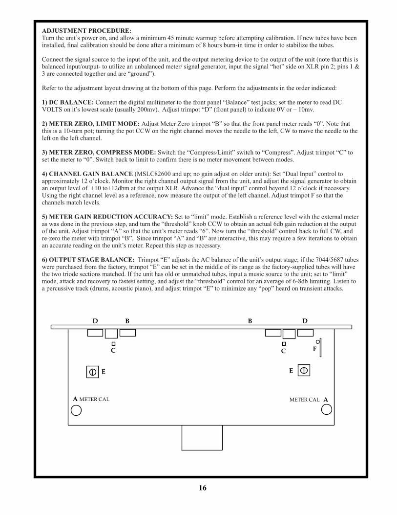
Refer to the adjustment layout drawing at the bottom of this page. Perform the adjustments in the order indicated:
1) DC BALANCE: Connect the digital multimeter to the front panel “Balance” test jacks; set the meter to read DC VOLTS on it’s lowest scale (usually 200mv). Adjust trimpot “D” (front panel) to indicate 0V or – 10mv.
2) METER ZERO, LIMIT MODE: Adjust Meter Zero trimpot “B” so that the front panel meter reads “0”. Note that this is a 10-turn pot; turning the pot CCW on the right channel moves the needle to the left, CW to move the needle to the left on the left channel.
3) METER ZERO, COMPRESS MODE: Switch the “Compress/Limit” switch to “Compress”. Adjust trimpot “C” to set the meter to “0”. Switch back to limit to confirm there is no meter movement between modes.
4) CHANNEL GAIN BALANCE (MSLC82600 and up; no gain adjust on older units): Set “Dual Input” control to approximately 12 o’clock. Monitor the right channel output signal from the unit, and adjust the signal generator to obtain an output level of +10 to+12dbm at the output XLR. Advance the “dual input” control beyond 12 o’clock if necessary. Using the right channel level as a reference, now measure the output of the left channel. Adjust trimpot F so that the channels match levels.
5) METER GAIN REDUCTION ACCURACY: Set to “limit” mode. Establish a reference level with the external meter as was done in the previous step, and turn the “threshold” knob CCW to obtain an actual 6db gain reduction at the output of the unit. Adjust trimpot “A” so that the unit’s meter reads “6”. Now turn the “threshold” control back to full CW, and re-zero the meter with trimpot “B”. Since trimpot “A” and “B” are interactive, this may require a few iterations to obtain an accurate reading on the unit’s meter. Repeat this step as necessary.
6) OUTPUT STAGE BALANCE: Trimpot “E” adjusts the AC balance of the unit’s output stage; if the 7044/5687 tubes were purchased from the factory, trimpot “E” can be set in the middle of its range as the factory-supplied tubes will have the two triode sections matched. If the unit has old or unmatched tubes, input a music source to the unit; set to “limit” mode, attack and recovery to fastest setting, and adjust the “threshold” control for an average of 6-8db limiting. Listen to a percussive track (drums, acoustic piano), and adjust trimpot “E” to minimize any “pop” heard on transient attacks.
C
A METER CAL
C
E
A METER CAL
D B B D
E
16
F