Embed Size (px)
Citation preview

11
にほんご
eng
lish
deu
tsch
fra
nça
isit
ali
an
o
Manual 1.3
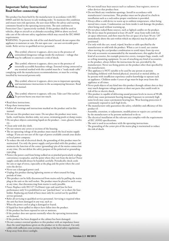
Important Safety Instructions! Read before connecting!
Th is product has been built by the manufacturer in accordance with IEC
60065 and left the factory in safe working order. To maintain this condition
and ensure non-risk operation, the user must follow the advice and warning
comments found in the operating instructions. Th e unit conforms to
Protection Class 1 (protectively earthed). If this product shall be used in
vehicles, ships or aircraft or at altitudes exceeding 2000 m above sea level,
take care of the relevant safety regulations which may exceed the IEC 60065
requirements.
WARNING: To prevent the risk of fi re and shock hazard, do not expose this
appliance to moisture or rain. Do not open case – no user serviceable parts
inside. Refer service to qualifi ed service personnel.
Th is symbol, wherever it appears, alerts you to the presence of
uninsulated dangerous voltage inside the enclosure – voltage that
may be suffi cient to constitute a risk of shock.
Th is symbol, wherever it appears, alerts you to the presence of
externally accessible hazardous voltage. External wiring connected to
any terminal marked with this symbol must be a “ready made cable”
complying with the manufacturers recommendations, or must be a wiring
installed by instructed persons only.
Th is symbol, wherever it appears, alerts you to important operating
and maintenance instructions in the accompanying literature. Read
the manual.
Th is symbol, wherever it appears, tells you: Take care! Hot surface!
To prevent burns you must not touch.
• Read these instructions.
• Keep these instructions.
• Follow all warnings and instructions marked on the product and in this
manual.
• Do not use this product near water. Do not place the product near water,
baths, wash basins, kitchen sinks, wet areas, swimming pools or damp rooms.
• Do not place objects containing liquid on the product – vases, glasses, bottles
etc.
• Clean only with dry cloth.
• Do not remove any covers or sections of the housing.
• Th e set operating voltage of the product must match the local mains supply
voltage. If you are not sure of the type of power available consult your dealer
or local power company.
• To reduce the risk of electrical shock, the grounding of this product must be
maintained. Use only the power supply cord provided with this product, and
maintain the function of the center (grounding) pin of the mains connection
at any time. Do not defeat the safety purpose of the polarized or grounding-
type plug.
• Protect the power cord from being walked on or pinched particularly at plugs,
convenience receptacles, and the point where they exit from the device! Power
supply cords should always be handled carefully. Periodically check cords
for cuts or sign of stress, especially at the plug and the point where the cord
exits the device.
• Never use a damaged power cord.
• Unplug this product during lightning storms or when unused for long
periods of time.
• Th is product can be fully disconnected from mains only by pulling the mains
plug at the unit or the wall socket. Th e product must be placed in such a way
at any time, that disconnecting from mains is easily possible.
• Fuses: Replace with IEC127 (5x20mm) type and rated fuse for best
performance only! It is prohibited to use “patched fuses” or to short the fuse-
holder. Replacing any kind of fuses must only be carried out by qualifi ed
service personal.
• Refer all servicing to qualifi ed service personnel. Servicing is required when
the unit has been damaged in any way, such as:
- When the power cord or plug is damaged or frayed.
- If liquid has been spilled or objects have fallen into the product.
- If the product has been exposed to rain or moisture.
- If the product does not operate normally when the operating instructions
are followed.
- If the product has been dropped or the cabinet has been damaged.
• Do not connect external speakers to this product with an impedance lower
than the rated impedance given on the product or in this manual. Use only
cables with suffi cient cross section according to the local safety regulations.
• Keep away from direct sunlight.
• Do not install near heat sources such as radiators, heat registers, stoves or
other devices that produce heat.
• Do not block any ventilation openings. Install in accordance with
manufacturer’s instructions. Th is product must not be placed in a built-in
installation such as a rack unless proper ventilation is provided.
• Always allow a cold device to warm up to ambient temperature, when being
moved into a room. Condensation can form inside it and damage the product,
when being used without warming up.
• Do not place naked fl ame sources, such as lighted candles on the product.
• Th e device must be positioned at least 20 cm/8" away from walls with free
air space inbetween, and there must be free air space of at least 50 cm / 20"
immediately above the unit within which no object(s) may be placed or
positioned.
• Use only with the cart, stand, tripod, bracket or table specifi ed by the
manufacturer or sold with the product. When a cart is used, use caution
when moving the cart/product combination to avoid injury from tip-over.
• Use only accessories recommended by the manufacturer, this applies for all
kind of accessories, for example protective covers, transport bags, stands, wall
or ceiling mounting equipment. In case of attaching any kind of accessories
to the product, always follow the instructions for use, provided by the
manufacturer. Never use fi xing points on the product other than specifi ed by
the manufacturer.
• Th is appliance is NOT suitable to be used by any person or persons
(including children) with limited physical, sensorical or mental ability, or
by persons with insuffi cient experience and/or knowledge to operate such
an appliance. Children under 4 years of age must be kept away from this
appliance at all times.
• Never push objects of any kind into this product through cabinet slots as they
may touch dangerous voltage points or short out parts that could result in
risk of fi re or electric shock.
• Th is product is capable of delivering sound pressure levels in excess of 90 dB,
which may cause permanent hearing damage! Exposure to extremely high
noise levels may cause a permanent hearing loss. Wear hearing protection if
continously exposed to such high levels.
• Th e manufacturer only guarantees the safety, reliability and effi ciency of this
product if:
- Assembly, extension, re-adjustment, modifi cations or repairs are carried out
by the manufacturer or by persons authorized to do so.
- Th e electrical installation of the relevant area complies with the requirements
of IEC (ANSI) specifi cations.
- Th e unit is used in accordance with the operating instructions.
- Th e grounding of the center pin of the mains plug is maintained to reduce
the risk of shock.
Version 2.3 08/2013
3
eng
lish
Things to Do Before Operating the Amp
• Please read these instructions carefully, particularly
the notes on safety, before operating the amp.
• The manufacturer disclaims any liability or
responsibility whatsoever for any damage or defect
to this and other devices resulting from misuse.
• Before you plug the TubeMeister 18 into a
mains power outlet, make sure its POWER and
STANDBY switches are off (both pointing down)
and that the voltage rating indicated on the amp’s
rear panel matches your local mains current.
• HEAD only: Please remember to always operate
the amp with a speaker connected. The only
exception to this rule is when the POWER SOAK
is set to the SPEAKER OFF position. Always
ensure the connected cabinet’s impedance is no less
than 8 Ω (see SPEAKER OUT for more on this).
• A word of warning before you fire up your
TubeMeister 18: It’s loud, and high volume levels
can cause hearing damage.
Table of contents
1Connections & Control Features
2 Standard Setup/Cable Connections
3 Tube Safety Control (TSC)
4 Technical Specifications
4
1Connections and Control Features
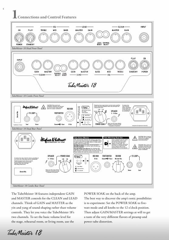
The TubeMeister 18 features independent GAIN
and MASTER controls for the CLEAN and LEAD
channels. Think of GAIN and MASTER as the
yin and yang of sound-shaping rather than volume
controls. They let you voice the TubeMeister 18’s
two channels. To set the basic volume level for
the stage, rehearsal room, or living room, use the
POWER SOAK on the back of the amp.
The best way to discover the amp’s sonic possibilities
is to experiment: Set the POWER SOAK to five-
watt mode and all knobs to the 12 o’clock position.
Then adjust GAIN/MASTER settings at will to get
a taste of the very different flavors of preamp and
power tube distortion.
TubeMeister 18 Head Front Panel
TubeMeister 18 Combo Front Panel
TSC™
SendReturn
DI Out8 - 16 Ohms Min MaxChannel Boost5 W 1 W18 W
POWER SOAK RED BOX FOOTSWITCH REVERB FX LOOPSPEAKER
Serial No.
Tube Status Monitor
TubeMeister 18 Head Rear Panel
TubeMeister 18 Combo Rear Panel
5
eng
lish
To avoid very loud and unwelcome surprises, make
a habit of backing the VOLUME knob of the guitar
connected to the TubeMeister all the way down
before switching on the amp.
1.1 Front Panel
POWER/ON
Set this switch to ON to get the mains power
flowing. The amp lights up and the tubes will begin
to heat up.
PLAY/STANDBY
Give the tubes about 30 seconds to warm up; then
you can flip the STANDBY switch to PLAY. The
amp is now ready to operate. When taking a short
break from playing, please use the STANDBY switch
so the tubes remain at operating temperature. This
protects them and ensures they last longer.
INPUT
Connect your guitar to this input using a shielded
cord.
CHANNEL SELECT
This switch activates either the CLEAN or LEAD
channel. Its LED lights up blue when you select the
LEAD channel. Connecting a footswitch disables
the front panel button. You can then switch channels
via footswitch only, and the CHANNEL SELECT
light indicates which channel is active.
CLEAN Channel
The CLEAN channel delivers warm tube tone.
Its dynamic range is considerable, sweeping from
pristine clean to throaty crunch sounds. Remarkably
responsive to the various pickup types, it also reacts
to the slightest nudge of the guitar’s volume knob.
GAIN
The GAIN knob determines the CLEAN channel’s
input sensitivity. Depending on the output levels of
the pickups in your instrument, the channel will begin
to overdrive somewhere around the 12 o'clock setting.
This knob does not influence the LEAD channel.
MASTER
This knob adjusts the CLEAN channel’s volume
without affecting the LEAD channel’s volume.
LEAD Channel
The LEAD channel delivers harmonically rich tube
distortion and plenty of gain reserves to go from
edgy overdrive to soaring lead sounds. You can even
clean up its tone by backing off the guitar’s volume
knob. This gives you a huge spectrum of sounds
to play with simply by working the pickup selector
switch and adjusting the volume knob.
GAIN
This knob adjusts the amount of tube distortion.
To discover the amazing range of sounds that this
channel puts at your fingertips, we recommend
that you first set the GAIN knob to the 12 o’clock
position, and then experiment with the guitar’s
volume knob, pickup selector, and the amp’s
BOOST switch.
MASTER
This knob adjusts the LEAD channel’s volume.
Again, first set GAIN to the 12 o’clock position
and experiment. If you wish to conjure creamy
lead tones, turn the knob well up to dial in smooth
power amp saturation. If you’re aiming for an
edgier metal sound, say for heavy riffs, try backing
off the MASTER knob and turning up the GAIN
knob. Usually smooth power amp saturation is less
desirable for this type of metal tone.
NOTE: Be advised that you cannot mute the
TubeMeister 18 by turning the LEAD MASTER knob
all the way down (to the far left position). If you wish
to play at very soft levels, we recommend that you
attenuate the amp’s overall output by selecting either
the five- or one-watt mode (see POWER SOAK)
rather than backing the MASTER volume way down.
LEAD BOOST
This switch re-voices the LEAD channel to summon
modern high-gain sound that pairs plenty of punch
with endless sustain. Its LED lights up red when
6
BOOST is active. Connecting a footswitch disables
the front panel button. You can then switch BOOST
via footswitch only, and the button merely serves to
indicate the function’s status.
BASS, MID, TREBLE
Although the two channels share these common
tone controls, their separate EQ filtering circuits are
voiced differently to achieve optimum results for
each channel.
1.2 Rear Panel
FX LOOP
This serial loop lets you patch in effects devices:
Connect the SEND jack to your effects processor's
input and the RETURN jack to the processor’s
output. The FX LOOP activates when you insert a
6.3 mm (1/4”) plug into the RETURN jack.
TIP
You can also use the SEND jack to tap the preamp
signal, for example, to patch it to another power
amp or a tuner. Conversely, you can use RETURN
to feed signals into the TubeMeister’s power amp.
In combination with the POWER SOAK and the
RED BOX Recording Out, this gives you a powerful
recording front end that offers very interesting re-
amping and sound-shaping options for just about
every conceivable signal.
REVERB (Combo only)
This knob adjusts the intensity of the onboard
digital spring reverb. We configured the reverb
circuit so that the effect is more pronounced with the
CLEAN channel than with the LEAD channel.
FOOTSWITCH
This standard stereo jack plug (tip = CHANNEL
SELECT; ring = LEAD BOOST) accepts a two-way
footswitch such as the Hughes & Kettner FS-2.
Button 1 switches between the CLEAN and LEAD
channels, and button 2 switches LEAD BOOST on
and off. It also accepts a one-way footswitch such as
the Hughes & Kettner FS-1 for switching channels.
TIP: This port gives you another hip remote-control
option: If you wish to control the TubeMeister 18
via MIDI, connect a MIDI switcher or looper to this
jack.
RED BOX
Invented by Hughes & Kettner, the RED BOX has
for years set the industry standard for analog guitar
DI boxes with built-in speaker emulation. It converts
the TubeMeister 18’s speaker out signal, which is
tapped post power amp and pre POWER SOAK,
into a balanced, frequency-compensated signal
that you can patch directly to a mixing console.
This signal it sounds very authentic, much like that
of a guitar amp, when rendered by a PA or studio
monitors,.
Use a microphone cord to patch this signal to a
mixing console. Make sure the mixing console’s XLR
input is set to line level. If the mixing console lacks
XLR inputs or if these cannot be set to line level, you
will need an XLR-to-6.3 mm-(1/4")-jack adapter
readily available in music stores. The channels’
MASTER settings directly affect the signal level, but
the selected POWER SOAK mode does not.
TSC
We devoted an entire chapter to the TUBE SAFETY
CONTROL. See section 3 to learn more about it.
POWER SOAK
Use this knob to adjust the TubeMeister 18’s output
power and set its basic volume level. This feature
lets you enjoy the benefits of full-blown power amp
saturation at low volume so you can play at home in
your living room without alienating the neighbors.
Its silent recording capability lets you capture
genuine tube-driven tone via a mixing console
without having to drive speakers. And if you want to
rehearse in silence any time day or night, simply plug
a set of headphones into the mixer.
The POWER SOAK is not just about managing
volume; it’s also about conjuring the right tone and
response. For modern sounds that demand fast,
7
eng
lish
tightly focused response, set the POWER SOAK to
full power and turn the MASTER knob down. If
you want classic rock sounds replete with spongier
power tube saturation, drop the POWER SOAK
down to a lower setting and crank the MASTER
knob to give those power tubes a workout.
The POWER SOAK offers the following modes:
Normal operation - full power at 18 watts
Power reduction to 5 watts
Power reduction to 1 watt
Mute (Speaker off) = 0 watts
Note that if you choose to mute the amp, you do
not need to connect a speaker to the TubeMeister
18’s SPEAKER output. Designed to enable silent
recording, this option provides the full signal to the
RED BOX output.
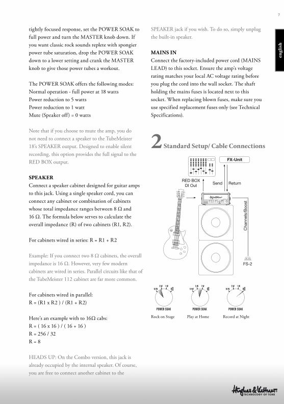
SPEAKER
Connect a speaker cabinet designed for guitar amps
to this jack. Using a single speaker cord, you can
connect any cabinet or combination of cabinets
whose total impedance ranges between 8 Ω and
16 Ω. The formula below serves to calculate the
overall impedance (R) of two cabinets (R1, R2).
For cabinets wired in series: R = R1 + R2
Example: If you connect two 8 Ω cabinets, the overall
impedance is 16 Ω. However, very few modern
cabinets are wired in series. Parallel circuits like that of
the TubeMeister 112 cabinet are far more common.
For cabinets wired in parallel:
R = (R1 x R2 ) / (R1 + R2)
Here’s an example with to 16Ω cabs:
R = ( 16 x 16 ) / ( 16 + 16 )
R = 256 / 32
R = 8
HEADS UP: On the Combo version, this jack is
already occupied by the internal speaker. Of course,
you are free to connect another cabinet to the
SPEAKER jack if you wish. To do so, simply unplug
the built-in speaker.
MAINS IN
Connect the factory-included power cord (MAINS
LEAD) to this socket. Ensure the amp's voltage
rating matches your local AC voltage rating before
you plug the cord into the wall socket. The shaft
holding the mains fuses is located next to this
socket. When replacing blown fuses, make sure you
use specified replacement fuses only (see Technical
Specifications).
2 Standard Setup/ Cable Connections
FX-Unit
RED BOXDI Out Send
FS-2
Return
Cha
nnel
s/B
oost
Rock on Stage Play at Home Record at Night
8
3 Tube Safety Control (TSC)
TSC adjusts bias to improve the amp’s tonal and
technical stability and extend power tubes’ life. It
does this automatically and continuously, so there is
nothing for you to do.
Swapping tubes is more easily, quickly, and safely
done than with a conventional amp. This is a big
help not only in case of a defect, but also when you
want to compare different brands of replacement
tubes.
CAUTION: Replacing tubes is a job for qualified
professionals! TSC merely spares the technician the
biasing effort.
What do the LEDs indicate?
Each LED is assigned to the power tube occupying
that same position. Getting a read-out of tubes’
operating status and bias points is easy using any
standard guitar pick.
3.1 Automatic status indications
All LEDs light up and stay on.
All LEDs remain on for as long as the amp is in
standby mode. They will extinguish when you
flip the STANDBY switch to PLAY after about 30
seconds. If the LEDs remain illuminated, the most
likely cause is a blown anode fuse that needs to be
replaced by a technician. The anode fuse can trip if
a tube is already defective when the amp is switched
on, and TSC does not have enough time to measure
idle current and shut the faulty tube down.
None of the LEDs lights up.
The power tubes are operating normally.
One LED lights up continuously.
The tube assigned to this LED is producing under-
voltage. If the LED does not extinguish after a few
minutes, this tube must be replaced.
One LED flashes constantly.
The tube assigned to this f lashing LED is generating
over-voltage. It has been shut down and must be
replaced by a technician. If the second LED lights
up continuously, this indicates it has also been shut
down for safety reasons, but there is no need to
replace it.
3.2 Manual Read-Out
TSC checks tubes’ bias points to let your determine
if pairs match. This is easily done by inserting a
pick into the appropriate slot while the amp is on
(rather than in STANDBY mode). The LEDs will
f lash. How many times the LEDs flash matters, but
what matters more is the difference in flash counts.
TSC will ensure optimum sound if the difference is
no greater than four flash signals. If the difference
in flash counts is greater than four, the device will
continue operating safely so there is no real need
to install a matched set. However, a matched set of
tubes will improve the tone.
9
eng
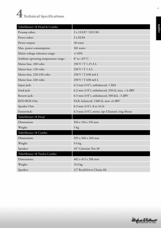
lishTubeMeister 18 Head & Combo
Preamp tubes: 2 x 12AX7 / ECC83
Power tubes: 2 x EL84
Power output: 18 watts
Max. power consumption: 101 watts
Mains voltage tolerance range: +/-10%
Ambient operating temperature range: 0° to +35° C
Mains fuse, 100 volts: 250 V / T 1.25 A L
Mains fuse, 120 volts: 250 V / T 1 A L
Mains fuse, 220-230 volts: 250 V / T 630 mA L
Mains fuse, 240 volts: 250 V / T 630 mA L
Input jack: 6.3 mm (1/4"), unbalanced, 1 MΩ
Send jack: 6.3 mm (1/4"), unbalanced, 250 Ω, max. + 6 dBV
Return jack: 6.3 mm (1/4"), unbalanced, 500 kΩ, -3 dBV
RED BOX Out: XLR, balanced, 1360 Ω, max +6 dBV
Speaker Out: 6.3 mm (1/4"), 8 to 16 Ω
Footswitch: 6.3 mm (1/4"), stereo, tip=Channel, ring=Boost
TubeMeister 18 Head
Dimensions: 356 x 156 x 150 mm
Weight: 5 kg
TubeMeister 18 Combo
Dimensions: 395 x 360 x 260 mm
Weight: 9.4 kg
Speaker: 10" Celestion Ten 30
TubeMeister 18 Twelve Combo
Dimensions: 482 x 413 x 288 mm
Weight: 15.4 kg
Speaker: 12" RockDriver Classic 60
4 Technical Specifications
Wichtige Sicherheitshinweise! Bitte vor Anschluss lesen!
Dieses Produkt wurde gemäß IEC 60065 hergestellt und hat das Werk in
einem sicheren, betriebsfähigen Zustand verlassen. Um diesen Zustand zu
erhalten und um einen gefahrlosen Betrieb zu gewährleisten, ist es notwendig,
dass der Benutzer die Empfehlungen und Warnhinweise befolgt, die in der
Betriebsanleitung zu fi nden sind. Dieses Gerät entspricht der Schutzklasse
1 (Erdungsschutz). Bei Einsatz dieses Produktes in Fahrzeugen, Schiff en
oder Flugzeugen, oder in Höhen oberhalb 2000 m Meereshöhe müssen die
entsprechenden Sicherheitsstandards zusätzlich zur IEC 60065 beachtet
werden.
WARNUNG: Um das Risiko von Feuer oder Stromschlag zu verhüten, darf
dieses Gerät nicht Feuchtigkeit oder Regen ausgesetzt werden. Öff nen Sie
das Gehäuse nicht – im Inneren gibt es keine Bauteile, die vom Benutzer
wartbar sind. Die Wartung darf nur von einem qualifi ziertem Kundendienst
durchgeführt werden.
Dieses Symbol, wo immer es erscheint, warnt Sie vor gefährlicher,
nicht isolierter Spannung im Gehäuse – Spannung, die
möglicherweise genügt, eine Stromschlaggefahr darzustellen.
Dieses Symbol, wo immer es erscheint, warnt Sie vor außen
zugänglicher, gefährlicher Spannung. Eine Verbindung zu jeder
Anschlussklemme, die mit diesem Symbol versehen ist, darf nur mit
konfektioniertem Kabel hergestellt werden, dass den Empfehlungen des
Herstellers genügt, oder mit Kabel, das von qualifi ziertem Personal installiert
wurde.
Dieses Symbol, wo immer es erscheint, macht Sie auf wichtige
Bedienungs- und Wartungsanweisungen aufmerksam, die in
beiliegenden Unterlagen zu fi nden sind. Bitte lesen Sie das
Handbuch.
Dieses Symbol, wo immer es erscheint, sagt Ihnen: Vorsicht! Heiße
Oberfl äche! Um Verbrennungen zu vermeiden, nicht anfassen.
• Bitte lesen Sie diese Anweisungen.
• Bewahren Sie diese Anweisungen auf.
• Befolgen Sie alle Warnhinweise und Anweisungen auf dem Gerät und in
dieser Anleitung.
• Benutzen Sie dieses Gerät nicht in der Nähe von Wasser. Stellen Sie das Gerät
nicht in der Nähe von Wasser, Badewannen, Waschbecken, Küchenspülen,
nassen Stellen, Schwimmbecken oder in feuchten Räumen auf.
• Stellen Sie keine Gefäße, wie Vasen, Gläser, Flaschen usw., die Flüssigkeiten
enthalten, auf das Gerät.
• Reinigen Sie das Gerät nur mit einem trockenen Tuch.
• Entfernen Sie keine Abdeckungen oder Teile des Gehäuses.
• Die auf dem Gerät eingestellte Betriebsspannung muss mit der örtlichen
Spannung der Netzstromversorgung übereinstimmen. Wenn Sie sich
nicht sicher sind, welche Spannung in Ihrem Netz zur Verfügung steht,
konsultieren Sie bitte Ihren Händler oder den örtlichen Stromversorger.
• Um das Risiko eines Stromschlags zu verringern, muss die Erdung
des Gerätes beibehalten werden. Verwenden Sie nur das mitgelieferte
Stromführungskabel und behalten Sie die Funktion der seitlichen, geerdeten
Schutzkontakte des Netzanschlusses immer aufrecht. Versuchen Sie nicht,
die Sicherheitsaufgabe des geerdeten Steckers zu umgehen.
• Schützen Sie das Stromführungskabel vor Betreten und Quetschen,
besonders in der Nähe der Stecker, Gerätesteckdosen – und dort, wo sie am
Gerät austreten! Stromführungskabel sollten immer vorsichtig behandelt
werden. Kontrollieren Sie die Stromführungskabel in regelmäßigen
Abständen auf Einschnitte und Anzeichen von Abnutzung, besonders in der
Nähe des Steckers und an der Verbindung zum Gerät.
• Benutzen Sie niemals ein beschädigtes Stromführungskabel.
• Ziehen Sie bei Gewittern den Stecker des Gerätes und wenn das Gerät über
einen längeren Zeitraum nicht benutzt wird.
• Dieses Gerät wird nur vollständig von Stromnetz getrennt, wenn der
Stecker vom Gerät oder aus der Steckdose gezogen wird. Das Gerät sollte so
aufgestellt werden, dass das Trennen vom Stromnetz leicht möglich ist.
• Sicherungen: Ersetzen Sie Sicherungen nur mit dem Typ IEC127 (5x20mm)
und dem korrekten Nennwert, um die optimale Leistung zu gewährleisten!
Es ist untersagt, kurzgeschlossene Sicherungen zu verwenden oder den
Sicherungshalter zu überbrücken. Sicherungen dürfen nur von qualifi ziertem
Personal gewechselt werden.
• Alle Wartungsarbeiten sollten nur von qualifi ziertem Personal ausgeführt
werden. Wartung ist notwendig, wenn das Gerät auf irgendeine Weise
beschädigt wurde, wie zum Beispiel:
- Wenn das Stromführungskabel oder der Stecker beschädigt oder abgenutzt
ist.
- Wenn Flüssigkeit oder Gegenstände in das Gerät gelangt sind.
- Wenn das Gerät Regen oder Feuchtigkeit ausgesetzt war.
- Wenn das Gerät nicht ordnungsgemäß funktioniert, obwohl die
Bedienungsanleitung beachtet wurde.
- Wenn das Gerät hingefallen ist oder das Gehäuse beschädigt wurde.
• Beim Anschluss von Lautsprechern an dieses Gerät darf die auf dem Gerät
oder in dieser Anleitung angegebene Mindestimpedanz nicht unterschritten
werden. Die verwendeten Kabel müssen entsprechend den lokalen
Regelungen über einen ausreichenden Querschnitt verfügen.
• Halten Sie das Gerät vom Sonnenlicht fern.
• Installieren Sie das Gerät nicht in der Nähe von Wärmequellen, wie zum
Beispiel Heizkörper, Heizregister, Öfen oder anderen Geräten, die Hitze
erzeugen.
• Verstopfen Sie nicht die Lüftungsöff nungen. Installieren Sie das Gerät
entsprechend der Anleitung des Herstellers. Das Gerät darf nicht eingebaut
werden – wie zum Beispiel in einen Gestellrahmen, es sei denn, dass für
angemessene Belüftung gesorgt wird.
• Ein kaltes Gerät sollte immer auf die Umgebungstemperatur erwärmt werden,
wenn es in einen Raum transportiert wird. Es könnte sich Kondensation im
Inneren bilden, die das Gerät beschädigt, wenn es ohne vorherige Erwärmung
benutzt wird.
• Stellen Sie keine off enen Flammen, wie brennende Kerzen, auf das Gerät.
• Das Gerät sollte mindestens 20 cm von Wänden aufgestellt werden, das Gerät
darf nicht bedeckt werden, es muss ein Freiraum von mindestens 50 cm über
dem Gerät gewährleistet sein.
• Das Gerät darf nur mit Rollwagen, Ständern, Stativen, Tischen oder
Halterungen benutzt werden, die vom Hersteller spezifi ziert sind oder
zusammen mit dem Gerät verkauft wurden. Wenn ein Rollwagen benutzt
wird, seien Sie vorsichtig, wenn Sie die Rollwagen/Geräte-Kombination
transportieren, um Verletzungen durch Umkippen zu vermeiden.
• Verwenden Sie nur Zubehör, das vom Hersteller empfohlen ist. Das
gilt für alle Arten von Zubehör, wie zum Beispiel Schutzabdeckungen,
Transporttaschen, Ständer sowie Wand- und Deckenhalterungen. Wenn Sie
irgendein Zubehör am Gerät anbringen, befolgen Sie immer die Anleitungen
des Herstellers. Benutzen Sie nur die Befestigungspunkte des Geräts, die vom
Hersteller vorgesehen sind.
• Dieses Gerät ist NICHT geeignet für eine Person oder Personen
(einschließlich Kindern) mit eingeschränkten physischen, sensorischen und
geistigen Fähigkeiten, oder für Personen mit unzulänglicher Erfahrung und/
oder Fachkenntnis, um solch ein Gerät zu bedienen. Kinder unter 4 Jahren
sollten stets von diesem Gerät fern gehalten werden.
• Es sollten keinerlei Gegenstände durch die Gehäuseschlitze eingeführt
werden, da dadurch gefährliche, spannungsführende Bauteile berührt
oder kurzgeschlossen werden können. Dies könnte zu einer Feuer- oder
Stromschlaggefahr führen.
• Dieses Gerät ist imstande, Schalldruckpegel von mehr als 90 dB zu
produzieren. Dies könnte zu einem dauerhaften Hörschaden führen! Eine
Belastung durch extrem hohe Geräuschpegel kann zu einem dauerhaften
Gehörverlust führen. Bei einer anhaltenden Belastung durch solch hohe Pegel
sollte ein Gehörschutz getragen werden.
• Der Hersteller gewährleistet die Sicherheit, Zuverlässigkeit und Leistung des
Gerätes nur unter folgenden Voraussetzungen:
- Einbau, Erweiterung, Neueinstellung, Modifi kationen oder Reparaturen
werden vom Hersteller oder autorisiertem Personal ausgeführt.
- Die elektrische Installation des betreff enden Bereiches entspricht den
Anforderungen der IEC (ANSI) Maßgaben.
- Das Gerät wird entsprechend der Bedienungsanleitung benutzt.
Version 2.3 08/2013
11
deu
tsch
Vor der Inbetriebnahme
• Vor der Inbetriebnahme diese Anleitung inklusive
der Sicherheitshinweise bitte sorgfältig durchlesen.
• Für Schäden am Gerät oder an anderen Geräten,
die durch unsachgemäßen Betrieb entstehen, kann
seitens des Herstellers keine Haftung übernommen
werden.
• Vor dem Anschluss des TUBEMEISTER 18 an
das Stromnetz muss sicher gestellt sein, dass der
POWER-Schalter und der STANDBY-Schalter
ausgeschaltet sind (beide zeigen nach unten) und der
angegebene Spannungswert auf der Rückseite mit
der ortsüblichen Netzspannung übereinstimmt.
• Nur bei HEAD: Bitte immer daran denken: außer in
der SPEAKER-OFF-Position des POWER SOAKs
immer mit einer angeschlossene Lautsprecher-Box
spielen und darauf achten, dass die Gesamtimpedanz
der angeschlossenen Boxen mindestens 8 Ω beträgt
(Siehe SPEAKER OUT)
• Ein Wort der Mahnung bevor der TUBEMEISTER
18 in Betrieb genommen wird: Er ist laut! Hohe
Lautstärke-Pegel können Gehörschäden verursachen.
Inhalt
1 Anschlüsse und Bedienelemente
2 Standard Setup/Verkabelung
3 Tube Safety Control
4 Technische Daten

12
1 Anschlüsse und Bedienelemente
Der TubeMeister 18 verfügt über unabhängige GAIN-
und MASTER-Regler im CLEAN- und im LEAD-
Kanal. GAIN und MASTER sind in beiden Kanälen
des TubeMeister 18 das Yin und Yang der Sound-
Gestaltung. Die Grundlautstärke, ob für die Bühne,
den Proberaum, oder das Wohnzimmer, bestimmt der
POWER SOAK auf der Rückseite des Amps.
Um die Vielseitigkeit der Kanäle zu erkunden empfeh-
len wir deshalb in der 5-Watt-Stellung des POWER
SOAKs und in der Mittelstellung aller Regler zu
beginnen, und dann durch verschiedenen GAIN/MA-
STER-Einstellungen die Sound-Welten der Vorstufen-
und Endstufenverzerrung zu entdecken.
TubeMeister 18 Head Vorderseite
TubeMeister 18 Combo Vorderseite
TSC™
SendReturn
DI Out8 - 16 Ohms Min MaxChannel Boost5 W 1 W18 W
POWER SOAK RED BOX FOOTSWITCH REVERB FX LOOPSPEAKER
Serial No.
Tube Status Monitor
TubeMeister 18 Head Rückseite
TubeMeister 18 Combo Rückseite
13
deu
tsch
Vor dem Einschalten das Volume-Poti der an den
TubeMeister angeschlossenen Gitarre bitte abdrehen
um laute Überraschungen zu vermeiden.
1.1 Vorderseite
POWER/ON
Öff net die Hauptstromzufuhr in Stellung ON:
Der Amp leuchtet, die Heizung der Röhren wird in
Betrieb genommen.
PLAY/STANDBY Schalter
Nach 30 Sekunden Aufwärmphase kann von STAND-
BY auf PLAY geschaltet werden, der Amp befi ndet
sich im Spielbetrieb. Bei kürzeren Spielpausen bitte
stets STANDBY benutzen, dann bleiben die Röhren
auf Betriebstemperatur. Dies schont die Röhren und
sorgt für eine längere Lebensdauer.
INPUT
Instrumenten-Eingang zum Anschluss der Gitarre
mittels eines abgeschirmten Klinkenkabels.
CHANNEL SELECT
Dieser Schalter dient zum Wechseln der Kanäle. Bei
Anwahl des LEAD-Kanals leuchtet er blau. Ist ein
Fußschalter angeschlossen, so ist diese Schaltfunktion
nur via Fußschalter ausführbar. Der CHANNEL
SELECT-Schalter dient dann als Anzeige.
CLEAN-Kanal
Der CLEAN-Kanal liefert warmen Röhrenton mit
einem extrem großem Dynamikumfang von glasklaren
Clean- bis organischen Crunch-Sounds. Er reagiert
sensibel auf die Stellung des Volume-Potis der Gitarre
und die Art des Pickups.
GAIN
Regelt den Grad der Eingangsempfi ndlichkeit des
CLEAN-Kanals. Je nach Ausgangspegel des Pickups
der Gitarre sind bereits in der Mittelstellung ange-
zerrte Sounds möglich. Dieser Regler hat keinen
Einfl uss auf den LEAD-Kanal.
MASTER
Regelt die Lautstärke des CLEAN-Kanals unabhängig
von der Lautstärke des LEAD-Kanals.
LEAD-Kanal
Der LEAD-Kanal liefert obertonreiche Röhrenverzer-
rung mit hohen Gain-Reserven von trockenen Drive-
bis cremigen Lead-Sounds. Sogar CLEAN-Sounds
sind bei zurückgenommenen Volume-Poti der Gitarre
möglich. Dadurch liefert er alleine durch die Wahl des
Pickups und der Stellung des Volume-Potis ein großes
Spektrum an Sounds.
GAIN
Regelt den Grad der Röhrenverzerrung. Um die Viel-
seitigkeit des Kanals zu entdecken empfehlen wir den
GAIN-Regler in Mittelstellung zu bringen und zuerst
mit dem Volume-Poti der Gitarre, der Pickup-Stellung
und dem BOOST-Schalter zu experimentieren.
MASTER
Regelt die Lautstärke des LEAD-Kanals. Auch hier gilt
es wie bei GAIN in Mittelstellung des Reglers zu be-
ginnen und zu experimentieren. Für cremige Sounds
darf er weit aufgedreht werden um eine weiche End-
stufensättigung zu erreichen. Für Metal-Riff -Sounds
ist es ratsam, den GAIN weit aufzudrehen und den
MASTER zurückzunehmen, da in diesem Fall eine
weiche Endstufensättigung eher unerwünscht ist.
HINWEIS: Durch Abdrehen des LEAD MASTER
(Linksanschlag) lässt sich der TubeMeister 18 nicht
vollständig stumm schalten. Wenn der Amps leise
gespielt werden soll ist es generell zu empfehlen zuerst
die Gesamtleistung des Amps auf 5 oder 1 Watt zu
reduzieren (siehe POWER SOAK) statt den MASTER
zu stark abzudrehen.
LEAD-BOOST
Dieser Schalter verwandelt den LEAD-Kanal in
einen modern abgestimmten High-Gain-Kanal mit
fettem Punch und endlosem Sustain. Ist der BOOST
aktiv, leuchtet der Schalter rot. Ist ein Fußschalter
angeschlossen, so ist diese Schaltfunktion nur via

14
Fußschalter ausführbar. Der BOOST-Schalter dient
dann als Anzeige.
BASS, MID, TREBLE
Gemeinsame Klangregelung für beide Kanäle. Um für
jeden Kanal optimale Klangergebnisse zu produzieren
wirkt die Filterung im CLEAN-Kanal anders als im
LEAD-Kanal.
1.2 Rückseite
FX LOOP
Über den seriellen Eff ektweg können externe Eff ekte
eingeschleift werden: SEND wird dabei mit dem
Eingang, RETURN mit dem Ausgang des Eff ektge-
rätes verbunden. Sobald sich ein Klinkenstecker in
RETURN befi ndet, ist der FX LOOP aktiv.
TIPP: SEND kann auch zum Abgreifen des Vorstu-
fen-Signals verwendet werden. So könnte an SEND
beispielsweise eine weitere Endstufe oder auch ein
Tuner angeschlossen werden. RETURN kann als Ein-
gang zur Nutzung der TubeMeister Endstufe genutzt
werden, was speziell in Verbindung mit dem POWER
SOAK und dem RED BOX Recording-Out extrem
interessante Möglichkeiten bietet um alle erdenklichen
Signale zu veredeln und aufzunehmen.
REVERB (nur Combo)
Regelt die Intensität des integrierten digitalen Feder-
Halls. Die Intensität ist automatisch so voreingestellt,
dass der Hall im CLEAN-Kanal stärker wirkt als im
LEAD-Kanal.
FOOTSWITCH
Standard-Stereoklinkenbuchse (Tip = CHANNEL
SELECT; Ring = LEAD BOOST) zum Anschluss
eines optional erhältlichen 2-fach Fußschalters (z.B.
Hughes & Kettner FS-2). Dieser schaltet mit dem er-
sten Taster zwischen CLEAN- und LEAD-Kanal um,
mit dem zweiten Taster den LEAD BOOST ein/aus.
Auch Einfach-Fußschalter (z.B. Hughes & Kettner
FS-1) funktionieren zur Umschaltung der Kanäle.
TIPP: Auch einen MIDI-Switcher / Looper kann hier
angeschlossen werden um den TUBEMEISTER 18
per MIDI zu steuern.
RED BOX
Die von Hugees & Kettner erfundene RED BOX ist
seit Jahren der Industrie-Standard für analoge Gitarren
DI-Boxen mit Speaker-Emulation. Sie wandelt das
Speaker-Out-Signal, welches beim TubeMeister 18
zwischen der Röhrenendstufe und dem POWER
SOAK abgegriff en wird, in ein symmetrisches,
frequenzkorrigiertes Signal um. Wird dieses Signal
über eine PA oder Studio-Monitore wiedergegeben,
entspricht der Höreindruck dem eines Gitarrenver-
stärkers.
Zum Anschluss an ein Mischpult wird ein Mikrofon-
Kabel verwendet. Der XLR-Eingang des Mischpultes
muss dabei zwingend auf Line-Pegel geschaltet sein.
Verfügt das Mischpult nicht über XLR-Eingänge oder
können diese nicht auf Line-Pegel geschaltet werden,
gibt es im Fachhandel entsprechende Adapter von
XLR auf Klinke. Der Pegel des Signals ist direkt von
der MASTER-Einstellung der Kanäle abhängig, aber
unabhängig von der Einstellung des POWER SOAKs.
TSC
Der TUBE-SAFETY-CONTROL haben wir ein extra
Kapitel gewidmet, siehe Kapitel 3.
POWER SOAK
Mit diesem Regler lässt sich die Ausgangsleistung
und damit die Grundlautstärke des TubeMeister 18
bestimmen. So kann man im heimischen Wohnzim-
mer bei geringer Lautstärke volle Endstufensättigung
genießen ohne Ärger mit den Nachbarn zu befürch-
ten, oder mitten in der Nacht echten Röhren-Sound
ganz ohne Lautsprecher über ein Mischpult und
Kopfhörer spielen und aufnehmen. Silent-Recording
lässt grüßen.
Aber nicht nur die Lautstärke, sondern auch der
Grundsound, oder besser gesagt, die bevorzugte
Spielweise und die dazu gehörige Sound-Erwartung
lässt sich mit dem POWER SOAK beeinfl ussen.
15
deu
tsch
Beispiel mit zwei 16-Ω-Boxen
R = ( 16 x 16 ) / ( 16 + 16 )
R = 256 / 32
R = 8
WICHTIG: Beim Combo ist dieser Anschluss
bereits vom internen Speaker belegt. Natürlich kann
der Klinkenstecker des Speakers einfach aus der
SPEAKER-Buchse herausgezogen und statt dessen
eine andere Gitarrenbox angeschlossen werden.
MAINS IN
Netzbuchse für das mitgelieferte Kabel (MAINS
LEAD). Stell vor Inbetriebnahme sicher, dass die
vorhandene Netzspannung mit der auf dem Gerät
angegebenen übereinstimmt. Bei der Netzbuchse be-
fi ndet sich auch der Schacht mit den Netzsicherungen.
Beim Austausch defekter Sicherungen unbedingt den
korrekten Wert einhalten (siehe Technische Daten).
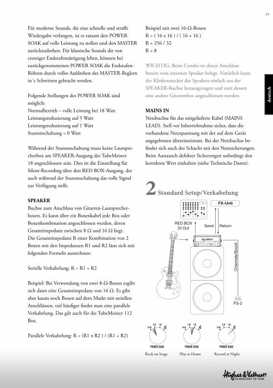
2 Standard Setup/Verkabelung
Für moderne Sounds, die eine schnelle und straff e
Wiedergabe verlangen, ist es ratsam den POWER
SOAK auf volle Leistung zu stellen und den MASTER
zurückzudrehen. Für klassische Sounds die von
cremiger Endstufensättigung leben, können bei
zurückgenommenen POWER SOAK die Endstufen-
Röhren durch volles Aufdrehen des MASTER-Reglern
in´s Schwitzen gebracht werden.
Folgende Stellungen des POWER SOAK sind
möglich:
Normalbetrieb – volle Leistung bei 18 Watt
Leistungsreduzierung auf 5 Watt
Leistungsreduzierung auf 1 Watt
Stummschaltung = 0 Watt
Während der Stummschaltung muss keine Lautspre-
cherbox am SPEAKER-Ausgang des TubeMeister
18 angeschlossen sein. Dies ist die Einstellung für
Silent-Recording über den RED BOX-Ausgang, der
auch während der Stummschaltung das volle Signal
zur Verfügung stellt.
SPEAKER
Buchse zum Anschluss von Gitarren-Lautsprecher-
boxen. Es kann über ein Boxenkabel jede Box oder
Boxenkombination angeschlossen werden, deren
Gesamtimpedanz zwischen 8 Ω und 16 Ω liegt.
Die Gesamtimpedanz R einer Kombination von 2
Boxen mit den Impedanzen R1 und R2 lässt sich mit
folgenden Formeln ausrechnen:
Serielle Verkabelung: R = R1 + R2
Beispiel: Bei Verwendung von zwei 8-Ω-Boxen ergibt
sich dann eine Gesamtimpedanz von 16 Ω. Es gibt
aber kaum noch Boxen auf dem Markt mit seriellen
Anschlüssen, viel häufi ger fi ndet man eine parallele
Verkabelung. Das gilt auch für die TubeMeister 112
Box.
Parallele Verkabelung: R = (R1 x R2 ) / (R1 + R2)
FX-Unit
RED BOXDI Out Send
FS-2
Return
Cha
nnel
s/B
oost
Rock on Stage Play at Home Record at Night
16
3 Die Tube-Safety-Control (TSC)
TSC arbeitet vollautomatisch und sorgt für eine
höhere klangliche und technische Stabilität sowie ein
längeres Leben der Endstufenröhren, indem es ständig
und automatisch den richtigen Ruhestrom einstellt.
Diese Grundfunktion bedarf keiner Bedienung.
Auch der Wechsel der Röhren ist schneller, einfacher
und sicherer als bei konventionellen Amps. Nicht nur
im Falle eines Defektes ist dies überaus hilfreich, son-
dern auch bei der Beurteilung von Austauschröhren
von verschiedenen Herstellern.
ACHTUNG: Der Röhrentausch darf ausschließlich
durch technisch qualifiziertes Fachpersonal erfolgen!
Es entfällt lediglich die manuelle Einmessung durch
den Techniker.
Was zeigen die LEDs an?
Jede der LEDs ist genau der Endstufen-Röhre in glei-
cher Position zugeordnet. Neben den Betriebszustän-
den der Röhren lassen sich die Anzeige der Röhren-
kennlinie ganz einfach mit einem Plektrum auslösen.
3.1 Automatische Anzeige:
Dauerleuchten aller LEDs
Solange sich der Amp im Standby-Betrieb befi ndet,
leuchten alle LEDs bis nach einer Aufwärmzeit von
ca. 30 Sekunden von STANDBY zu PLAY geschaltet
wird. Leuchten alle LEDs weiterhin, ist höchstwahr-
scheinlich die Anodensicherung defekt und muss von
einem Techniker ausgetauscht werden. Die Anoden-
sicherung kann trotz TSC durchbrennen, wenn eine
Röhre bereits vor dem Einschalten des Amps defekt
ist, und TSC keine Zeit bleibt den Ruhestrom zu mes-
sen und jene defekte Röhre rechtzeitig abzuschalten.
Keine LED leuchtet
Die Endstufen-Röhren laufen technisch im Normal-
zustand.
Dauerleuchten einer einzelnen LED
Die betreff ende Röhre erzeugt Unterstrom und wurde
abgeschaltet. Sollte sich das Dauerleuchten nicht
nach wenigen Minuten einstellen, muss diese Röhre
ausgewechselt werden.
Dauerblinken einer einzelnen LED
Die Röhre erzeugt einen Überstrom. Diese Röhre
wurde abgeschaltet und muss von einem Techniker
ausgewechselt werden. Zeigt die zweite LED ein Dau-
erleuchten, so wurde diese Röhre zur Sicherheit mit
abgeschaltet, muss aber nicht ausgewechselt werden.
3.2 Manuelle Anzeige
TSC erlaubt das Überprüfen der Kennlinien, wodurch
sogar ein „matchen“ der Röhren (Auswahl von
Röhren mir gleicher Kennlinie) möglicht ist. Dazu
mit einem Plektrum während des Spielbetriebs (nicht
in STANDBY) in den dafür vorgesehenen Schlitz
neben den LEDs drücken. Die LEDs fangen nun an
zu blinken. Entscheidend ist dabei weniger, wie oft die
LEDs blinken, sondern wie unterschiedlich oft. Bis
zu einer Abweichung von 4 Blinkzeichen garantiert
TSC optimalen Sound, bei einer höheren Abweichung
ist ein Röhrenwechsel aus klanglicher Sicht empfoh-
len, technisch ergeben sich aber immer noch keine
Nachteile.
17
deu
tsch
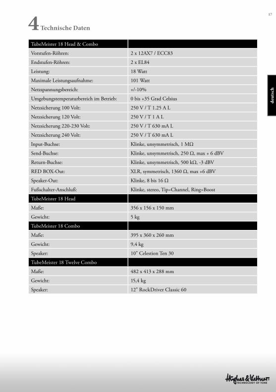
4 Technische Daten
TubeMeister 18 Head & Combo
Vorstufen-Röhren: 2 x 12AX7 / ECC83
Endstufen-Röhren: 2 x EL84
Leistung: 18 Watt
Maximale Leistungsaufnahme: 101 Watt
Netzspannungsbereich: +/-10%
Umgebungstemperaturbereich im Betrieb: 0 bis +35 Grad Celsius
Netzsicherung 100 Volt: 250 V / T 1.25 A L
Netzsicherung 120 Volt: 250 V / T 1 A L
Netzsicherung 220-230 Volt: 250 V / T 630 mA L
Netzsicherung 240 Volt: 250 V / T 630 mA L
Input-Buchse: Klinke, unsymmetrisch, 1 MΩ
Send-Buchse: Klinke, unsymmetrisch, 250 Ω, max + 6 dBV
Return-Buchse: Klinke, unsymmetrisch, 500 kΩ, -3 dBV
RED BOX-Out: XLR, symmetrisch, 1360 Ω, max +6 dBV
Speaker-Out: Klinke, 8 bis 16 Ω
Fußschalter-Anschluß: Klinke, stereo, Tip=Channel, Ring=Boost
TubeMeister 18 Head
Maße: 356 x 156 x 150 mm
Gewicht: 5 kg
TubeMeister 18 Combo
Maße: 395 x 360 x 260 mm
Gewicht: 9,4 kg
Speaker: 10" Celestion Ten 30
TubeMeister 18 Twelve Combo
Maße: 482 x 413 x 288 mm
Gewicht: 15,4 kg
Speaker: 12" RockDriver Classic 60
Consignes de sécurité importantes ! A lire avant de se connecter !
Ce produit a été construit conformément à la norme IEC 60065 par le
fabricant et a quitté l’usine en bon état de marche. Pour garantir son intégrité
et un fonctionnement sans risque, l’utilisateur se doit de suivre les conseils et
les avertissements préconisés dans cette notice d’utilisation. Les unités sont
conformes à la classe de protection 1 (protection par mise à la terre). En cas
d’utilisation de ce produit dans un véhicule terrestre, un navire ou un avion,
ou encore à une altitude supérieure à 2 000 mètres, il convient de prendre en
considération les normes de sécurité suivantes, en plus de la norme IEC 60065.
ATTENTION : Afi n d’éviter tout risque d'incendie et d'électrocution,
n'exposez pas cet appareil à l’humidité ou à la pluie. N’ouvrez pas le boîtier ;
les pièces se trouvant à l’intérieur ne nécessitent pas d’entretien de la part des
utilisateurs. Adressez-vous à un spécialiste qualifi é pour procéder à l'entretien
de l'appareil.
Ce symbole, quel que soit l’endroit où il apparaît, vous signale des
pièces sous tension non isolées dans le boîtier. Une tension suffi sante
pour présenter un risque d’électrocution.
Ce symbole, quel que soit l’endroit où il apparaît, vous signale des
pièces sous tension accessibles depuis l’extérieur du boîtier. Tous les
câbles extérieurs raccordés à un composant marqué de ce symbole
doivent être de type préfabriqués et conformes aux spécifi cations du fabricant
ou doivent avoir été installés par des spécialistes qualifi és.
Ce symbole, quel que soit l’endroit où il apparaît, vous signale des
instructions importantes relatives à l’utilisation ou l’entretien de
l’appareil à lire dans les documents l’accompagnant. Lisez la notice
d’utilisation.
Ce symbole, quel que soit l’endroit où il apparaît, vous signale un
risque de brûlure dû à une surface chaude. Ne touchez pas cette
surface afi n d’éviter de vous brûler.
• Lisez ces instructions.
• Conservez ces instructions.
• Prenez en compte tous les avertissements et toutes les instructions mentionnés
sur le produit ou dans cette notice d’utilisation.
• N’utilisez pas ce produit à proximité de l’eau. Ne le placez pas près de l’eau,
d’une baignoire, d’un bassin, d’un évier, d’une surface humide, d’une piscine
ou d’une pièce humide.
• Ne mettez pas d’objet contenant du liquide sur l’appareil, par exemple, un
vase, un verre ou une bouteille, etc.
• Nettoyez-le exclusivement avec un chiff on sec.
• N’enlevez pas le boîtier, ne serait-ce que partiellement.
• La tension de fonctionnement de l’appareil doit être réglée de manière à
correspondre à la tension d’alimentation de l’endroit où vous vous trouvez. Si
vous n’êtes pas sûr de connaître la tension d’alimentation, demandez à votre
revendeur ou à la compagnie d’électricité locale.
• Afi n de réduire le risque d’électrocution, vous ne devez jamais supprimer
la mise à la terre de l’appareil. Utilisez uniquement le câble d’alimentation
fourni avec le produit et maintenez la broche centrale de la prise (mise à la
terre) en état de fonctionnement. Ne négligez pas la sécurité off erte par les
prises polarisées ou avec mise à la terre.
• Protégez le câble d’alimentation afi n d’éviter que quelqu’un marche dessus ou
qu’il soit pincé, notamment près de la prise, de la prise murale ou à la sortie
de l’appareil même ! Les câbles d’alimentation doivent être tout le temps
maniés avec précaution. Vérifi ez régulièrement que le câble n’est pas fendu
ou qu’il ne présente pas de signe d’usure, en particulier près de la prise et à la
sortie de l’appareil.
• N’utilisez jamais de câble d’alimentation usé.
• Débranchez l’appareil en cas d’orage ou si vous ne l’utilisez pas pendant une
longue période.
• Débranchez l’appareil uniquement en le tenant par la prise au niveau de la
prise murale ou de la rallonge. L’appareil doit être placé de telle manière à ce
qu’il puisse être débranché facilement à tout moment.
• Fusibles : si nécessaire, remplacez-les uniquement par des fusibles de type
IEC127 (5x20 mm) afi n de garantir une meilleure performance. Il est interdit
d’utiliser des fusibles bricolés ou de raccourcir le porte-fusible. Seul un
personnel qualifi é est habilité à remplacer les fusibles.
• Confi ez tous les travaux d’entretien à des spécialistes qualifi és. Il est
nécessaire d’eff ectuer de tels travaux lorsque l’unité a été endommagée,
comme par exemple dans les cas suivants :
- Lorsque le câble d’alimentation est endommagé ou effi loché.
- Si du liquide a pénétré ou un objet est tombé dans le boîtier.
- Si l’appareil a été exposé à la pluie ou à l’humidité.
- Si l’appareil ne fonctionne pas correctement alors que vous avez suivi toutes
les instructions à la lettre.
- Si l’appareil est tombé ou que le boîtier est endommagé.
• En cas de raccordement de haut-parleurs à cet appareil, il faut veiller à ne pas
descendre sous l’impédance minimale indiquée sur ledit appareil ou dans la
présente notice. Les câbles employés doivent présenter une section suffi sante,
qui soit conforme aux réglementations locales en vigueur.
• Ne l’exposez pas directement aux rayons du soleil.
• Ne l’installez pas à proximité d’une source de chaleur, telle qu’un radiateur,
une grille de chauff age, un four ou tout autre appareil susceptible de produire
de la chaleur.
• Ne masquez pas les bouches d’aération. Installez l’appareil conformément
aux instructions du fabricant. Il ne doit pas être placé dans un emplacement
confi né, comme un rack ou une console, sauf si une ventilation suffi sante est
garantie.
• Si vous déplacez l’appareil, attendez qu’il soit à température ambiante avant
de le démarrer, sinon de la condensation peut se former à l’intérieur et
endommager l’appareil.
• Ne posez pas de d’objet à fl amme ouverte sur l’appareil, comme par exemple
une bougie allumée.
• L'appareil doit être situé à 20 cm minimum des murs, il ne doit en aucun cas
être couvert et il convient de prévoir un espace d'au moins 50 cm au-dessus
de l'appareil.
• Utilisez l’appareil uniquement avec un chariot, un support, un trépied, des
fi xations ou une table recommandés par le fabricant ou vendus avec le produit.
Si vous utilisez un chariot, maniez-le avec précaution afi n d’éviter tout risque
de blessure s’il se renverse.
• Utilisez uniquement les accessoires recommandés par le fabricant. Cette
consigne concerne toute sorte d’accessoires, qu’il s’agisse de couvercles de
protection, de sacs de transport, de supports ou de dispositifs de fi xation au
mur ou au plafond. Si vous fi xez un accessoire à l’appareil, suivez toujours
les instructions d’utilisation du fabricant. N’utilisez pas d’autres points de
fi xation que ceux préconisés par le fabricant.
• Cet appareil NE convient PAS aux personnes dont les capacités motrices,
sensorielles ou mentales sont défi cientes (y compris les enfants) ou aux
personnes ne disposant pas de l’expérience ou des connaissances nécessaires
pour faire fonctionner le présent appareil. Cet appareil doit dans tous les cas
et être tenu constamment hors de portée des enfants de moins de quatre ans.
• N’insérez jamais d'objets à travers les grilles du boîtier, car ils pourraient
toucher des pièces sous tension dangereuses ou provoquer un court-circuit
pouvant causer un risque d’incendie ou d’électrocution.
• Cet appareil est capable de délivrer un niveau de pression acoustique
de 90 dB, pouvant ainsi causer des troubles irréversibles de l’audition !
L’exposition continue à une nuisance sonore peut provoquer une perte
d’audition permanente. Portez des protections auditives adéquates si vous
vous exposez de manière continue à un tel niveau de pression acoustique.
• Le fabricant garantit la sécurité, la fi abilité et l’effi cacité de fonctionnement
de son produit uniquement si :
- l’assemblage, l’extension, le réajustement, la modifi cation ou la réparation de
l’appareil ont été eff ectués par le fabricant ou par des personnes agréées pour
ce genre de travaux.
- l’installation électrique concernée est conforme aux normes IEC (ANSI).
- l’unité est utilisée conformément aux instructions d’utilisation.
Version 2.3 08/2013
19
Avant la mise en marche
• Avant de mettre en marche l’appareil, lisez avec
attention cette notice d’utilisation ainsi que tous les
avis de sécurité.
• Le fabricant ne peut être tenu pour responsable de
tout dommage survenu sur cet appareil ou un autre,
suite à une utilisation non conforme.
• Avant de raccorder le TUBEMEISTER 18 au
réseau électrique, vous devez vous assurer que les
commutateurs POWER et STANDBY sont bien
éteints (ils sont tous les deux basculés en position
basse) et que la tension indiquée au dos de l’appareil
correspond bien à celle du réseau électrique local.
• HEAD (Tête TubeMeister 18) uniquement : pensez
à toujours jouer avec une enceinte branchée sauf si le
POWER SOAK est en position SPEAKER OFF et
assurez-vous que l’impédance totale des enceintes est
bien supérieure à 8 ohms (voir SPEAKER OUT).
• Un avertissement avant que vous ne branchiez votre
TUBEMEISTER 18 : il est bruyant ! Un niveau
sonore élevé peut provoquer des lésions irréversibles
du système auditif.
Sommaire
1 Connectique et contrôles
2 Raccordement et configuration standard
3 Tube Safety Control
4 Fiche technique
fra
nça
is
20
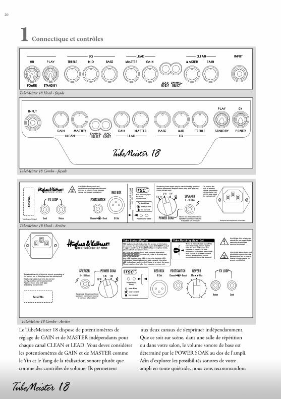
1 Connectique et contrôles
Le TubeMeister 18 dispose de potentiomètres de
réglage de GAIN et de MASTER indépendants pour
chaque canal CLEAN et LEAD. Vous devez considérer
les potentiomètres de GAIN et de MASTER comme
le Yin et le Yang de la réalisation sonore plutôt que
comme des contrôles de volume. Ils permettent
aux deux canaux de s’exprimer indépendamment.
Que ce soit sur scène, dans une salle de répétition
ou dans votre salon, le volume sonore de base est
déterminé par le POWER SOAK au dos de l’ampli.
Afin d’explorer les possibilités sonores de votre
ampli en toute quiétude, nous vous recommandons
TubeMeister 18 Head - façade
TubeMeister 18 Combo - façade
TSC™
SendReturn
DI Out8 - 16 Ohms Min MaxChannel Boost5 W 1 W18 W
POWER SOAK RED BOX FOOTSWITCH REVERB FX LOOPSPEAKER
Serial No.
Tube Status Monitor
TubeMeister 18 Head - Arrière
TubeMeister 18 Combo - Arrière
21
de commencer en réglant le POWER SOAK sur 5
watts et tous les potentiomètres en position médiane.
Vous pourrez ensuite tester à volonté les différentes
combinaisons GAIN/MASTER, et découvrir ainsi
les fantastiques variétés de sons offertes par la
combinaison d’un préampli et d’un amplificateur à
lampes.
Pour éviter tout bruit violent et inattendu, avant
d’allumer votre ampli, , prenez l’habitude de baisser
complètement le volume de la guitare raccordée au
TubeMeister.
1.1 Façade
POWER/ON
Alimentation principale. Mise en marche en position
ON : le témoin de l’amplificateur est allumé et les
tubes chauffent.
Commutateur PLAY/STANDBY
Après 30 secondes de préchauffage, vous pouvez régler
le commutateur de STAND-BY sur PLAY, l’ampli
est prêt à l’utilisation. Lorsque vous faites une courte
pause, mettez l’ampli en STANDBY, ainsi les tubes
restent à température. Cela les ménage et augmente
leur longévité.
INPUT
Connectez y votre guitare à l’aide d’un câble jack
blindé.
CHANNEL SELECT
Ce commutateur sert à changer de canal. Si vous
sélectionnez le canal LEAD, le témoin s’allume en
bleu. Si une pédale est raccordée à l’ampli, vous
ne pouvez alors accéder à cette fonction que par le
biais de cette pédale. La lumière de l’interrupteur
CHANNEL SELECT sert alors à afficher le canal
sélectionné.
Canal CLEAN
Le canal CLEAN offre le son chaud à lampes. Sa plage
dynamique est très large et permet d’aller du son le
plus cristallin au crunch décoiffant. Elle offre une
réponse exceptionnelle en fonction du type de micro
et elle réagit également aux diverses variations de la
position du potentiomètre de volume de la guitare.
GAIN
Permet de régler le niveau de sensibilité d’entrée
du canal CLEAN. Selon le volume sonore en sortie
du micro de la guitare, il est possible que de la
distorsion apparaisse déjà en position médiane. Cette
potentiomètre de réglage n’a aucune influence sur le
canal LEAD.
MASTER
Permet de régler le volume du canal CLEAN,
indépendamment du volume du canal LEAD.
Canal LEAD
Le canal LEAD offre une distorsion riche en
harmoniques avec une grande réserve de gain, vous
permettant d’aller du simple Drive à des sons Lead
beaucoup plus riches. Vous pouvez même obtenir
des sons plus clairs en baissant au maximum le
potentiomètre de volume de la guitare. Il vous offre
ainsi une large gamme de sonorités, juste en jouant
avec le sélecteur de micros et le réglage de volume de
votre guitare.
GAIN
Permet de régler le niveau de saturation de la lampe.
Pour découvrir la diversité des possibilités sonores qui
vous sont offertes par ce canal, nous vous conseillons
de mettre le potentiomètre de réglage du GAIN
en position médiane et d’expérimenter différentes
combinaisons de paramètres tels que la position du
sélecteur de micro, le réglage de volume de la guitare
et le bouton BOOST de l’ampli.
MASTER
Permet de régler le volume du canal LEAD. Tout
comme pour le réglage du GAIN, commencez là
aussi avec le potentiomètre en position médiane et
expérimentez. Pour obtenir des sons de lead plus
riches, vous pouvez le tourner ce potentiomètre à
fond pour obtenir une légère saturation de l’étage
fra
nça
is
22
d’amplification.
Pour jouer des Riff de Metal, il vous faudra
plutôt augmenter le GAIN et réduire le niveau
du MASTER, car une saturation de l’étage
d’amplification n’est pas souhaitable pour obtenir ce
type de sonorité.
REMARQUE : vous ne pourrez pas couper
complètement le son du TubeMeister 18 en baissant
complètement le volume de la section LEAD
MASTER (En tournant la potentiomètre à fond vers
la gauche). En règle générale, si vous souhaitez jouer
plus silencieusement avec l’ampli, vous devrez tout
d’abord réduire sa puissance totale à 5 ou 1 watt (voir
POWER SOAK) au lieu de réduire le volume du
MASTER.
LEAD-BOOST
Cet interrupteur transforme le canal LEAD en un
canal high gain moderne avec un punch d’enfer et
un sustain infini. Si la fonction BOOST est active,
l’interrupteur s’allume en rouge. Si une pédale est
raccordée à l’ampli, vous ne pouvez accéder à cette
fonction que par le biais de la pédale. L’interrupteur
BOOST sert alors uniquement à afficher si la fonction
est sélectionnée.
BASS, MID, TREBLE
Bien que les deux canaux partagent ces réglages de
tonalité, ils bénéficient de circuits d’égalisation séparés
qui sont ajustés différemment afin de produire une
sonorité optimale pour chaque canal.
1.2 Face arrière
FX LOOP
Cette boucle d’effet vous permet d’intégrer des
effets externes : SEND doit être raccordé à la prise
d’entrée de votre processeur d’effets et RETURN à sa
sortie. Dès qu’une fiche jack est branchée sur la prise
RETURN, FX LOOP est activé.
ASTUCE : la sortie SEND peut aussi être utilisé
pour prélever le signal de préamplification. Ainsi
vous pouvez par exemple y connecter un autre étage
d’amplification ou un accordeur. RETURN peut être
utilisé comme une entrée vers l’étage d’amplification
du TubeMeister. Ceci offre des possibilités
particulièrement intéressantes pour améliorer ou
enregistrer toutes sortes de sons, si vous l’utilisez
en combinaison avec le POWER SOAK et la sortie
enregistrement de la RED BOX.
REVERB (Version Combo uniquement)
Permet de régler l’intensité de la Reverb numérique
intégrée. L’intensité est préréglée, de manière à ce que
la réverbération agisse plus sur le canal CLEAN que
sur le canal LEAD.
FOOTSWITCH
Prise jack stéréo standard (pointe = CHANNEL
SELECT ; anneau = LEAD BOOST) permet de
connecter un double interrupteur de type FS-2
Hughes & Kettner. Le premier bouton permet de
choisir les canaux CLEAN ou LEAD, alors que
le second permet d’activer ou désactiver le LEAD
BOOST. Les interrupteurs simples comme par
exemple le FS-1 Hughes & Kettner permettent
également de commuter les canaux.
ASTUCE : vous pouvez aussi raccorder un
MIDI switcher ou un loopeur pour contrôler le
TUBEMEISTER 18 en MIDI.
RED BOX
La RED BOX inventée par Hughes & Kettner est
considérée depuis des années comme un standard sur
le marché des DI box analogiques pour guitares avec
émulation d’enceinte. Elle transforme le signal de
sortie de l’enceinte, prélevé entre l’étage de sortie et
le POWER SOAK du TubeMeister 18, en un signal
symétrique à fréquence corrigée qui peut être envoyé
directement dans une console de mixage. Ceci permet
de restituer le son authentique d’un ampli de guitare
même s’il est retransmis par le biais d’un système de
sonorisation ou des moniteurs de studio.
Pour le raccordement à une console de mixage, il
convient d’utiliser un câble de micro. L’entrée XLR de
23
la console doit impérativement être au niveau ligne.
Si elle ne dispose pas d’entrée XLR ou si celle-ci ne
peut pas être mise au niveau ligne, vous devrez utiliser
un adaptateur XLR-jack que vous trouverez dans
les magasins spécialisés. Le niveau du signal dépend
directement du réglage MASTER des canaux, mais
pas du réglage du POWER SOAK.
TSC
Un chapitre est spécialement dédié au TUBE SAFETY
CONTROL, voir chapitre 3.
POWER SOAK
Ce potentiomètre permet de déterminer la puissance
de sortie et donc le volume de base du TubeMeister
18. Vous pouvez ainsi profiter pleinement de la
richesse du son saturé d’un étage d’amplification à
faible volume dans votre salon, ce qui peut s’avérer
très positif pour vos relations de voisinage. Sa fonction
d’enregistrement silencieux vous permet de capturer
le son de votre ampli à lampes pour vous permettre
de jouer ou de l’enregistrer sans utiliser d’enceinte,
par le biais d’une console de mixage et d’écouteurs à
n’importe quelle du jour ou de la nuit.
Ceci dit le POWER SOAK ne permet pas uniquement
d’agir sur le volume, mais aussi d’agir sur la sonorité
et la réponse de l’ampli. Pour des sons modernes
qui nécessitent une réponse rapide et un son assez
sec, il est conseillé de régler le POWER SOAK sur
sa puissance maximale et de baisser le MASTER.
Pour des sons Rock plus classiques demandant
une distorsion plus riche, augmentez la valeur
du potentiomètre MASTER tout en réduisant la
puissance du POWER SOAK.
Le POWER SOAK vous offre les réglages suivants :
Fonctionnement normal – puissance maximale à 18
watts
Réduction de la puissance à 5 watts
Réduction de la puissance à 1 watt
Mute (silencieux, plus de sortie HP) = 0 watt
En mode silencieux, il n’est pas nécessaire qu’une
enceinte soit raccordée à la sortie SPEAKER
du TubeMeister 18. Elle permet de réaliser des
enregistrements en mode silencieux en envoyant la
totalité du signal par la sortie RED BOX.
MAINS IN
Prise d’alimentation pour le câble fourni (MAINS
LEAD). Avant la mise en marche, assurez-vous que
la tension du réseau local correspond à celle indiquée
sur l’appareil. C’est également là que se trouve le
boîtier à fusibles. Si vous devez en changer un, veillez
à bien respecter les valeurs de référence (voir fiche
technique).
SPEAKER
Sortie de raccordement pour enceintes de guitare.
N’importe quelle enceinte ou combinaison d’enceintes
peut être raccordée par le biais d’un câble d’enceinte,
du moment que l’impédance totale se situe entre 8 et
16 ohms. L’impédance totale R d’une combinaison de
deux enceintes ayant pour impédance R1 et R2 peut
être calculée selon la formule suivante :
Raccordement en série : R = R1 + R2
Exemple : Si vous utilisez deux enceintes de 8
ohms, l’impédance totale est de 16 ohms. Il
n’existe néanmoins presque plus d’enceintes avec
raccordement en série sur le marché. Le plus souvent
elles sont raccordées en parallèle. C’est également le
cas de l’enceinte TubeMeister 112.
Câblage parallèle : R = (R1 x R2) / (R1 + R2)
Exemple avec deux enceintes de 16 ohms
R = (16 x 16) / (16 + 16)
R = 256 / 32
R = 8
IMPORTANT : sur le Combo, cette prise est déjà
occupée par le haut-parleur interne. Naturellement
la fiche jack du haut-parleur peut être retirée de la
prise SPEAKER pour raccorder une autre enceinte de
guitare.
fra
nça
is
24
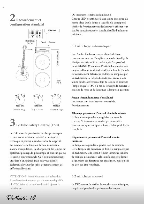
2 Raccordement et
configuration standard
FX-Unit
RED BOXDI Out Send
FS-2
Return
Cha
nnel
s/B
oost
Rock on Stage Play at Home Record at Night
3 Le Tube Safety Control (TSC)
Le TSC ajuste la polarisation des lampes au repos
et vous assure ainsi une stabilité acoustique et
technique et permet ainsi d’accroître la longévité
des lampes. Cette fonction de base ne nécessite
aucune manipulation. Le changement des lampes est
également plus rapide, plus simple et plus sûr que sur
les amplis conventionnels. Ce n’est pas uniquement
utile lors d’une panne, mais cela vous permet
également d’évaluer les tubes de remplacement de
différents fabricants.
ATTENTION : le remplacement des tubes doit
être effectué uniquement par du personnel qualifié
! Le TSC évite au technicien d’avoir à ajuster la
polarisation.
Qu’indiquent les témoins lumineux ?
Chaque LED est attribuée à une lampe et se situe à la
même place que la lampe à laquelle elle correspond.
Vérifier le fonctionnement des lampes et afficher leur
courbe caractéristique est simple, il suffit d’utiliser un
médiator.
3.1 Affichage automatique
Les témoins lumineux restent allumés de façon
permanente tant que l’ampli est en mode Standby, ils
s’éteignent environ 30 secondes après être passés du
mode STANDBY au mode PLAY. Si les témoins sont
toujours allumés au-delà de ce délai, le fusible d’anode
est certainement défectueux et doit être remplacé par
un technicien. Le fusible d’anode peut sauter si une
lampe est déjà défectueuse lors de la mise en route de
l’ampli et que le TSC n’a pas eu le temps de mesurer le
courant de repos et de désactiver la lampe en question.
Aucun témoin lumineux n’est allumé
Les lampes sont dans leur état normal de
fonctionnement.
Allumage permanent d’un seul témoin lumineux
La lampe correspondante ne génère pas assez de
courant. Si le témoin ne s’éteint pas de manière
permanente après quelques minutes, la lampe doit être
remplacée.
Clignotement permanent d’un seul témoin
lumineux
La lampe correspondante génère trop de courant.
Cette lampe a été désactivée et doit être remplacée par
un technicien. Si le second témoin lumineux s’allume
de manière permanente, cela signifie que cette lampe
a également été désactivée par précaution, mais qu’elle
ne doit pas être remplacée.
3.2 Affichage manuel
Le TSC permet de vérifier les courbes caractéristiques,
ce qui rend possible l’appariement des lampes
25
(sélection de lampes ayant les mêmes courbes
caractéristiques). Pour ce faire, vous devez uniquement
glisser un médiator dans la fente prévue à cet effet et
située à côté des témoins lumineux (en mode PLAY
et non en mode STANDBY). Les témoins lumineux
commencent alors à clignoter. Le plus important
n’est pas combien de fois les témoins clignotent, mais
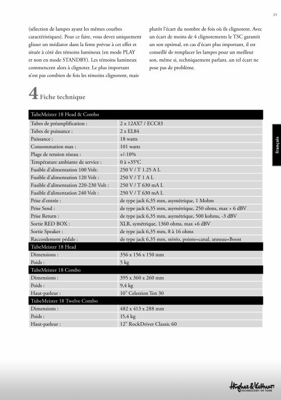
TubeMeister 18 Head & Combo
Tubes de préamplification : 2 x 12AX7 / ECC83
Tubes de puissance : 2 x EL84
Puissance : 18 watts
Consommation max : 101 watts
Plage de tension réseau : +/-10%
Température ambiante de service : 0 à +35°C
Fusible d’alimentation 100 Volt: 250 V / T 1.25 A L
Fusible d’alimentation 120 Volt : 250 V / T 1 A L
Fusible d’alimentation 220-230 Volt : 250 V / T 630 mA L
Fusible d‘alimentation 240 Volt : 250 V / T 630 mA L
Prise d’entrée : de type jack 6,35 mm, asymétrique, 1 Mohm
Prise Send : de type jack 6,35 mm, asymétrique, 250 ohms, max + 6 dBV
Prise Return : de type jack 6,35 mm, asymétrique, 500 kohms, -3 dBV
Sortie RED BOX : XLR, symétrique, 1360 ohms, max +6 dBV
Sortie Speaker : de type jack 6,35 mm, 8 à 16 ohms
Raccordement pédale : de type jack 6,35 mm, stéréo, pointe=canal, anneau=Boost
TubeMeister 18 Head
Dimensions : 356 x 156 x 150 mm
Poids : 5 kg
TubeMeister 18 Combo
Dimensions : 395 x 360 x 260 mm
Poids : 9,4 kg
Haut-parleur : 10" Celestion Ten 30
TubeMeister 18 Twelve Combo
Dimensions : 482 x 413 x 288 mm
Poids : 15,4 kg
Haut-parleur : 12" RockDriver Classic 60
plutôt l’écart du nombre de fois où ils clignotent. Avec
un écart de moins de 4 clignotements le TSC garantit
un son optimal, en cas d’écart plus important, il est
conseillé de remplacer les lampes pour un meilleur
son, même si, techniquement parlant, un tel écart ne
pose pas de problème.
4 Fiche technique
fra
nça
is
Istruzioni di sicurezza importanti. Leggere prima di effettuare il collegamento!
Il presente prodotto è stato fabbricato dal produttore in conformità alla
norma IEC 60065 ed è uscito dallo stabilimento in perfette condizioni
di funzionamento. Per preservare tali condizioni e garantirne l’uso
sicuro, l’utente deve attenersi alle indicazioni e alle avvertenze riportate
nelle istruzioni per l’uso. L’unità è conforme alla Classe di protezione 1
(apparecchio con messa a terra di protezione). Se volete usare questo prodotto
su veicoli, a bordo di navi o di aerei oppure ad altitudini superiori a 2000 m
dovete badare alle rispettive norme di sicurezza suppletive alla norma IEC
60065.
AVVISO: Per evitare il rischio di incendio o folgorazione, non esporre
l’apparecchio ad umidità o pioggia. Non aprire l’involucro poiché al suo
interno non vi sono parti riparabili dall’utente. Per la riparazione rivolgersi a
personale tecnico qualifi cato.
Questo simbolo segnala la presenza all’interno dell’involucro di
tensione pericolosa priva di isolamento suffi cientemente alta da
costituire un pericolo di folgorazione.
Questo simbolo segnala la presenza di tensione pericolosa accessibile
dall’esterno. Il cablaggio esterno collegato ad un qualunque morsetto
contrassegnato da questo simbolo deve essere un cavo
preconfezionato conforme ai requisiti indicati dal produttore o un cablaggio
installato da personale qualifi cato.
Questo simbolo segnala importanti istruzioni per l’uso e la
manutenzione nella documentazione allegata. Leggere il manuale.
Questo simbolo ha il seguente signifi cato: Attenzione! Superfi cie
calda! Non toccare per evitare scottature.
• Leggere queste istruzioni.
• Conservare queste istruzioni.
• Attenersi a tutti gli avvisi e istruzioni riportati sul prodotto e nel manuale.
• Non utilizzare il prodotto vicino all’acqua. Non collocare il prodotto vicino
ad acqua, vasche, lavandini, zone umide, piscine o stanze con presenza di
vapore.
• Non collocare sul prodotto oggetti contenenti liquidi, quali vasi, bicchieri,
bottiglie ecc.
• Pulire solo con un panno asciutto.
• Non togliere alcun coperchio o parti dell’involucro.
• La tensione di esercizio prescritta per il prodotto deve corrispondere alla
tensione di alimentazione della rete locale. In caso di dubbi sul tipo di
alimentazione disponibile, rivolgersi al proprio rivenditore o all’azienda di
fornitura elettrica locale.
• Per ridurre il rischio di folgorazione, la messa a terra del prodotto deve
essere mantenuta. Utilizzare solo il cavo di alimentazione in dotazione al
prodotto e mantenere sempre in funzione il connettore centrale (di terra) del
collegamento alla rete. Non escludere la funzione di sicurezza del connettore
polarizzato o di messa a terra.
• Proteggere il cavo di alimentazione affi nché non venga calpestato o pizzicato,
in particolare in corrispondenza delle prese e degli innesti e nel punto di
uscita dal dispositivo. Maneggiare sempre con cura i cavi di alimentazione.
Controllare periodicamente la presenza di tagli o usura sui cavi, soprattutto
all’altezza della presa e nel punto di uscita dal dispositivo.
• Non utilizzare mai il cavo di alimentazione se danneggiato.
• Scollegare il prodotto in caso di temporale o di lunghi periodi di inutilizzo.
• Il prodotto si scollega completamente dall’alimentazione di rete solo
staccando la spina di alimentazione dall’unità o dalla presa a muro. Il
prodotto va collocato sempre in modo che sia possibile scollegarlo
dall’alimentazione con facilità.
• Fusibili: per garantire prestazioni ottimali, i fusibili utilizzati come ricambio
devono essere di tipo IEC127 (5x20 mm) e dell’amperaggio nominale
richiesto. È vietato utilizzare fusibili riparati o cortocircuitare il portafusibili.
Fate sostituire i fusibili soltanto da un tecnico qualifi cato.
• Per tutte le operazioni di riparazione, rivolgersi a personale qualifi cato.
L’unità va riparata nel caso abbia subito danni, come nei seguenti casi:
- Il cavo o la presa di alimentazione sono danneggiati o usurati.
- È penetrato del liquido o degli oggetti all’interno del prodotto.
- Il prodotto è stato esposto a pioggia o umidità.
- Il prodotto non funziona correttamente seguendo le istruzioni.
- Il prodotto ha subito una caduta o l’armadio è stato danneggiato.
• Quando collegate altoparlanti badate di non scendere sotto l’impedenza
minima dichiarata sull’apparecchio oppure in questo manuale. Usate sempre
cavi dello spessore adatto e corrispondenti alle vigenti norme locali.
• Non esporre ai raggi solari diretti.
• Non installare accanto a fonti di calore quali radiatori, bocchette di
diff usione d’aria calda, fornelli o altri dispositivi che generano calore.
• Non chiudere le aperture di ventilazione. Installare l’unità seguendo le
istruzioni fornite dal produttore. Il prodotto non è adatto all’installazione
ad incasso, ad esempio in un rack, a meno di non garantire un’adeguata
ventilazione.
• Quando viene spostato all’interno di un locale, attendere sempre che il
dispositivo, se freddo, raggiunga la temperatura ambiente. Qualora venga
utilizzato senza che si sia riscaldato, sussiste il rischio di formazione di
condensa al suo interno e di conseguenti danni.
• Non collocare sul prodotto fi amme libere, come ad esempio candele accese.
• Posate l’apparecchio mantenendo una distanza minima di 20 cm da pareti.
Non copritelo e provvedete a lasciare uno spazio libero di almeno 50 cm al di
sopra dell’apparecchio.
• Utilizzare solo in abbinamento al carrello, supporto, piedistallo, staff a o
tavola specifi cati dal produttore o venduti insieme al prodotto. Qualora
si utilizzi un carrello, prestare attenzione nello spostare il carrello/la
combinazione di prodotto per evitare lesioni causate dall’inciampamento.
• Utilizzare solo accessori consigliati dal produttore. Tale prescrizione si
applica a tutti i tipi di accessori, ad esempio coperchi di protezione, borse per
il trasporto, supporti, dispositivi per il montaggio a parete o a soffi tto, ecc.
In caso di applicazione di qualsiasi tipo di accessorio al prodotto, osservare
sempre le istruzioni per l’uso fornite dal produttore. Non utilizzare mai punti
di fi ssaggio sul prodotto diversi da quelli indicati dal produttore.
• Questo apparecchio NON è adatto all’uso da parte di persone (compresi i
bambini) con capacità fi siche, mentali o sensoriali limitate o da persone prive
della necessaria esperienza e/o conoscenza. Tenere sempre l’apparecchio al di
fuori della portata dei bambini di età inferiore ai 4 anni.
• Non inserire mai oggetti di alcun tipo all’interno del prodotto attraverso
le fessure dell’armadio, poiché potrebbero toccare punti con presenza
di tensione pericolosa o causare il cortocircuito dei componenti, con il
conseguente rischio di incendio o folgorazione.
• Questo prodotto genera livelli di pressione sonora superiori a 90 dB in grado
di causare danni permanenti all’udito. L’esposizione a livelli di rumore
estremamente elevati può causare la perdita permanente dell’udito. In caso di
esposizione continua, indossare protezioni per l’udito.
• Il produttore garantisce la sicurezza, l’affi dabilità e l’effi cienza del prodotto
solo se:
- l’assemblaggio, l’ampliamento, la reimpostazione, le modifi che o le
riparazioni sono eseguiti dal produttore o da personale autorizzato.
- l’impianto elettrico dell’area interessata è conforme ai requisiti specifi cati
nelle norme IEC (ANSI).
- l’unità è utilizzata secondo le istruzioni per l’uso.
Version 2.3 08/2013
27
Cose da fare prima di usare l’ampli
• Prima di utilizzare l’ampli, si prega di leggere
attentamente queste istruzioni, particolarmente le
note sulla sicurezza.
• Qualunque cosa accada, Il produttore rifiuta
qualsiasi obbligo o responsabilità per qualsiasi danno
o difetto a questo o ad altri dispositivi derivante da
un cattivo uso.
• Prima di collegare il TubeMeister 18 ad una
presa elettrica, assicuratevi che i suoi interruttori
di POWER e STANDBY siano OFF (entrambi
verso il basso) e che la tensione di targa indicata
nel pannello posteriore dell’ampli corrisponda alla
vostra tensione locale di rete.
• Solo Testata: ricordatevi sempre di far funzionare
l’ampli collegato ad un cabinet. L’unica eccezione a
questa regola è quando il selettore POWER SOAK
è su OFF. Accertatevi sempre che l’impedenza del
cabinet non sia inferiore ad 8 Ω (vedi per maggiori
dettagli SPEAKER OUT).
• Un avvertimento prima di accendere il vostro
TubeMeister 18: il suo suono ad alti livelli di volume
può provocare danni all’udito.
Indice
1Caratteristiche di Controllo e Connessioni
2 Setup Standard/Cavi di Connessione
3 Tube Safety Control (TSC)
4 Specifiche Tecniche
ita
lia
no
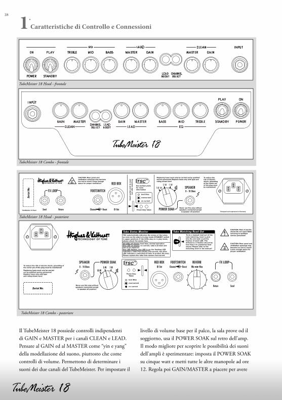
28
Il TubeMeister 18 possiede controlli indipendenti
di GAIN e MASTER per i canali CLEAN e LEAD.
Pensate al GAIN ed al MASTER come “yin e yang”
della modellazione del suono, piuttosto che come
controlli di volume. Permettono di determinare i
suoni dei due canali del TubeMeister. Per impostare il
livello di volume base per il palco, la sala prove od il
soggiorno, usa il POWER SOAK sul retro dell’amp.
Il modo migliore per scoprire le possibilità dei suoni
dell’ampli è sperimentare: imposta il POWER SOAK
su cinque watt e metti tutte le altre manopole ad ore
12. Regola poi GAIN/MASTER a piacere per avere
TubeMeister 18 Head - frontale
TubeMeister 18 Combo - frontale
TSC™
SendReturn
DI Out8 - 16 Ohms Min MaxChannel Boost5 W 1 W18 W
POWER SOAK RED BOX FOOTSWITCH REVERB FX LOOPSPEAKER
Serial No.
Tube Status Monitor
TubeMeister 18 Head - posteriore
TubeMeister 18 Combo - posteriore
1.
Caratteristiche di Controllo e Connessioni
29
un assaggio dei suoni molto differenti dovuti alla
distorsione del preamplificatore o delle valvole finali.
Per evitare sorprese molto forti e non volute, prima di
accendere l’ampli, prendi l’abitudine di abbassare del
tutto il volume della chitarra collegata al TubeMeister.
1.1 Pannello frontale
POWER/ON
Sposta questo switch su ON per fornire
l’alimentazione. L’ampli si illumina e le valvole
inizieranno a riscaldarsi.
PLAY/STANDBY
Dai alle valvole 30 secondi per riscaldarsi; poi puoi
mettere lo switch da STANDBY su PLAY. L’ampli è
ora pronto funzionare. Quando smetti di suonare per
un breve break, usa lo switch STANDBY in modo
che le valvole rimangano in temperatura. Questo le
protegge e ne assicura una maggiore durata.
INPUT
Collega la tua chitarra a questo ingresso utilizzando un
cavo schermato.
CHANNEL SELECT
Questo switch attiva sia il canale CLEAN che
quello LEAD. Quando selezioni il canale LEAD il
LED si illuminerà in blù. Collegando una pedaliera
si disattivano i tasti del pannello frontale. Potrai
poi cambiare i canali solo dalla pedaliera e la luce
CHANNEL SELECT ti indica quale canale è attivo.
Canale CLEAN
Il canale CLEAN fornisce il tono caldo delle valvole.
La sua dinamica è considerevole, passando dal suono
lead puro al roco crunch. Notevolmente sensibile
ai vari tipi di pickup, reagisce anche alle minime
variazioni della manopola del volume della chitarra.
GAIN
La manopola del GAIN determina la sensibilità
d’ingresso del canale CLEAN. A seconda del livello
di uscita del pickup del tuo strumento, il canale
comincerà a sovra pilotare intorno ad ore 12. Questa
manopola non influenza il canale LEAD.
MASTER
Questa manopola regola il volume del canale clean
senza influire sul volume del canale LEAD.
Canale LEAD
Il canale LEAD fornisce la distorsione ricca di
armoniche delle valvole e un abbondante riserva di
gain per andare da un sound overdrive tagliente ad
un sublime suono lead. Puoi anche pulire il suono
diminuendo il volume della chitarra. Questo ti
fornisce un enorme spettro di suoni per suonare
semplicemente lavorando sul selettore dei pickup e
regolando la manopola del volume.
GAIN
Questa manopola regola la quantità di distorsione
della valvola. Per scoprire la sorprendente gamma di
suoni che questo canale ti mette a portata di mano, ti
raccomandiamo prima di impostare il GAIN ad ore
12 e poi di sperimentare con il volume della chitarra,
il selettore dei pickup e con lo switch BOOST
dell’ampli.
MASTER
Questa manopola regola il volume del canale
LEAD. Di nuovo, prima imposta il GAIN ad ore
12 e sperimenta. Se vuoi creare tonalità morbide,
ruota la manopola bene fino ad arrivare alla levigata
saturazione dell’ampli. Se stai cercando un suono
metal più tagliente, diciamo per un riff heavy, prova a
diminuire la manopola MASTER ed aumentare quella
del GAIN. Di solito per questo tipo di tono metal,
una saturazione morbida dell’ampli è meno piacevole.
NOTA: ti avvertiamo che non puoi silenziare il
TubeMeister 18 ruotando la manopola LEAD
MASTER tutta verso sx (al minimo). Se vuoi suonare
a livelli molto soft, ti consigliamo di attenuare l’uscita
dell’amplificatore selezionando sia il modo cinque che
quello un watt (vedi POWER SOAK) piuttosto che
regolare il volume MASTER tutto verso sx.
ita
lia
no
30
LEAD BOOST
Questo switch modifica il tono del canale LEAD
richiamando moderni suoni high-gain, che
accoppiano punch abbondante con sustain senza fine.
Il suo LED si illumina in rosso quando il BOOST
è attivo. Collegando una pedaliera si disabilita il
tasto sul pannello frontale. In questo caso puoi solo
attivare il BOOST dalla pedaliera ed il tasto serve
semplicemente ad indicare lo stato della funzione.
BASS, MID, TREBLE
Sebbene i due canali condividano questi controlli di
tono, i loro circuiti di EQ separati hanno un voicing
diverso per fornire un risultato ottimo per ciascun
canale.
1.2 Pannello posteriore
FX LOOP
Questo loop seriale permette di collegare gli effetti
esterni: collega il jack SEND all’ingresso del tuo
processore effetti ed il jack RETURN all’uscita del
processore. Il LOOP FX si attiva quando inserisci un
jack da ¼” nella presa jack RETURN.
SUGGERIMENTO
Puoi anche usare il jack SEND per prelevare il segnale
preamp, ad esempio, per collegarlo ad un altro ampli o
ad un accordatore.
Al contrario, puoi anche usare il RETURN per
immettere segnali nell’ampli del TubeMeister.
Combinato con il POWER SOAK e l’uscita
Recording Out della RED BOX, questo ti fornisce un
potente terminale di registrazione che offre interessanti
opzioni di modellazione del suono e di amplificazione
per tutti i segnali immaginabili.
REVERB (solo combo)
Questa manopola regola l’intensità del riverbero
digitale a molla interno. Abbiamo configurato il
circuito del riverbero in maniera che l’effetto sia più
pronunciato con il canale CLEAN piuttosto che con
il LEAD.
FOOTSWITCH
Questa presa jack stereo standard (punta =
CHANNEL SELECT; anello = LEAD BOOST)
accetta una pedaliera a due vie come la Hughes &
Kettner FS-2.
Lo switch 1 commuta tra i canali CLEAN e LEAD,
lo switch 2 commuta il LEAD BOOST on e off.
Accetta anche una pedaliera a una via come l’FS-1 per
commutare tra i canali.
SUGGERIMENTO: questa porta ti da un’altra
moderna opzione di controllo-remoto del TubeMeister
18 via MIDI, collega un MIDI switcher o looper a
questo jack.
RED BOX
Inventata da Hughes & Kettner la RED BOX è
stata per anni lo standard dell’industria delle DI box
analogiche per chitarra con emulazione del cabinet.
Converte il segnale d’uscita del TubeMeister 18, che
è prelevato post power amp e pre POWER SOAK,
in un segnale bilanciato, compensato in frequenza,
che puoi collegare direttamente ad una console di
mixaggio. Questo segnale suona come autentico,
molto simile a quello dell’ampli, se reso da un PA o da
un monitor da studio.
Usa un cavo microfonico per inviare il segnale al
mixer. Assicurati l’ingresso del mixer sia impostato
a livello line. Se il mixer non ha gli ingressi XLR o
se non si possono commutare su line, allora ti serve
un adattatore XLR/1/4” facilmente reperibile nei
negozi musicali. Le impostazioni MASTER dei canali
influiscono direttamente sul livello del segnale, ma
non il modo selezionato del POWER SOAK.
TSC
Abbiamo riservato un intero capitolo sul TUBE
SAFETY CONTROL. Vedi la Sezione 3 per saperne
di più.
POWER SOAK
Usa questa manopola per regolare la potenza d’uscita
del TubeMeister ed impostare il suo livello base di
volume. Questa caratteristica ti lascia godere dei
benefici della saturazione dell’amplificatore di
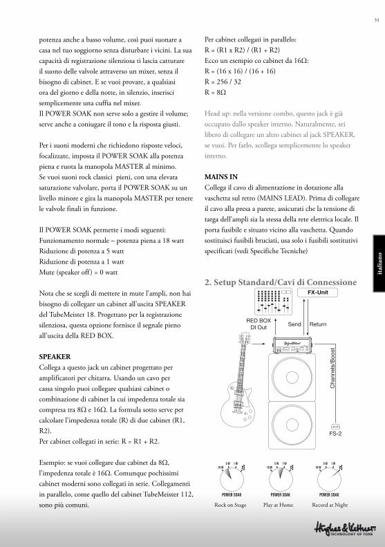
31
potenza anche a basso volume, così puoi suonare a
casa nel tuo soggiorno senza disturbare i vicini. La sua
capacità di registrazione silenziosa ti lascia catturare
il suono delle valvole attraverso un mixer, senza il
bisogno di cabinet. E se vuoi provare, a qualsiasi
ora del giorno e della notte, in silenzio, inserisci
semplicemente una cuffia nel mixer.
Il POWER SOAK non serve solo a gestire il volume;
serve anche a coniugare il tono e la risposta giusti.
Per i suoni moderni che richiedono risposte veloci,
focalizzate, imposta il POWER SOAK alla potenza
piena e ruota la manopola MASTER al minimo.
Se vuoi suoni rock classici pieni, con una elevata
saturazione valvolare, porta il POWER SOAK su un
livello minore e gira la manopola MASTER per tenere
le valvole finali in funzione.
Il POWER SOAK permette i modi seguenti:
Funzionamento normale – potenza piena a 18 watt
Riduzione di potenza a 5 watt
Riduzione di potenza a 1 watt
Mute (speaker off ) = 0 watt
Nota che se scegli di mettere in mute l’ampli, non hai
bisogno di collegare un cabinet all’uscita SPEAKER
del TubeMeister 18. Progettato per la registrazione
silenziosa, questa opzione fornisce il segnale pieno
all’uscita della RED BOX.
SPEAKER
Collega a questo jack un cabinet progettato per
amplificatori per chitarra. Usando un cavo per
cassa singolo puoi collegare qualsiasi cabinet o
combinazione di cabinet la cui impedenza totale sia
compresa tra 8Ω e 16Ω. La formula sotto serve per
calcolare l’impedenza totale (R) di due cabinet (R1,
R2).
Per cabinet collegati in serie: R = R1 + R2.
Esempio: se vuoi collegare due cabinet da 8Ω,
l’impedenza totale è 16Ω. Comunque pochissimi
cabinet moderni sono collegati in serie. Collegamenti
in parallelo, come quello del cabinet TubeMeister 112,
sono più comuni.
Per cabinet collegati in parallelo:
R = (R1 x R2) / (R1 + R2)
Ecco un esempio co cabinet da 16Ω:
R = (16 x 16) / (16 + 16)
R = 256 / 32
R = 8Ω
Head up: nella versione combo, questo jack è già
occupato dallo speaker interno. Naturalmente, sei
libero di collegare un altro cabinet al jack SPEAKER,
se vuoi. Per farlo, scollega semplicemente lo speaker
interno.
MAINS IN
Collega il cavo di alimentazione in dotazione alla
vaschetta sul retro (MAINS LEAD). Prima di collegare
il cavo alla presa a parete, assicurati che la tensione di
targa dell’ampli sia la stessa della rete elettrica locale. Il
porta fusibile e situato vicino alla vaschetta. Quando
sostituisci fusibili bruciati, usa solo i fusibili sostitutivi
specificati (vedi Specifiche Tecniche)
2. Setup Standard/Cavi di ConnessioneFX-Unit
RED BOXDI Out Send
FS-2
ReturnC
hann
els/
Boo
st
Rock on Stage Play at Home Record at Night
ita
lia
no
32
3 Tube Safety Control (TSC)
Il TSC regola il bias per migliorare la tonalità e la
stabilità tecnica dell’amplificato ed aumentare la
vita delle valvole finali. Lo fa automaticamente e
continuamente, perciò non c’è nulla che tu debba fare.
Cambiare le valvole è più semplice, veloce ed in
sicurezza rispetto ad un ampli convenzionale.
Questo è un grande aiuto non solo in caso di
malfunzionamento, ma anche quando vuoi
confrontare marchi differenti di valvole sostitutive.
ATTENZIONE: sostituire le valvole è un lavoro per
professionisti qualificati. TSC semplicemente ti fa
risparmiare il lavoro di un tecnico per tarare il bias.
Che cosa indicano i LED?
Ciascun LED è assegnato a ciascuna valvola finale che
occupa la stessa posizione. Dare un’occhiata allo stato
di funzionamento delle valvole ed ai punti di bias è
semplice, con l’uso di qualsiasi penna standard per
chitarra.
3.1 Indicazioni automatiche di stato
Tutti i LED sono illuminati e rimangono accesi
Tutti i LED rimangono accesi fino a quando l’ampli è
nel modo standby. Si spegneranno quando, dopo circa
30 secondi, sposterai lo switch da STANDBY a PLAY.
Se i LED rimangono accesi, la causa più probabile
è un fusibile dell’anodo bruciato che necessita
essere sostituito da un tecnico. Il fusibile dell’anodo
può saltare se una valvola è già difettosa prima che
venga acceso l’ampli ed il TSC non ha ancora avuto
abbastanza tempo per misurare la corrente a riposo e
spegnere la valvola difettosa.
Nessun LED è acceso
Le valvole di potenza stanno funzionando
regolarmente.
Un LED è acceso fisso
La valvola assegnata a quel LED sta producendo una
sotto-tensione. Se il LED non si spegne entro pochi
minuti, questa valvola deve essere sostituita.
Un LED lampeggia costantemente
La valvola assegnata a quel LED sta generando una
sovra-tensione. E’ stata spenta e deve essere sostituita
da un tecnico. Se il secondo LED si accende fisso,
questo indica che anche la seconda valvola è stata
spenta per ragioni di sicurezza, ma non è necessario di
sostituirla.
3.2 Manual Read-Out
Il controllo dei punti di bias di TSC vi permette di
capire se le due valvole di potenza sono accoppiate
correttamente. Questo si fa facilmente inserendo
una penna nella fessura appropriata quando l’ampli
è on (piuttosto che nel modo STANDBY). I LED
lampeggeranno.
Non ha importanza quante volte i LED lampeggiano,
ma, quello che importa di più è la differenza nel
conteggio dei flash. TSC assicurerà un suono ottimo
se la differenza non è maggiore di quattro segnali
di flash. Se la differenza è maggiore di quattro,
il dispositivo continuerà a lavorare in sicurezza
senza nessuna necessità effettiva di istallare un set
accoppiato. Tuttavia, un set accoppiato di valvole
migliorerà il tono.
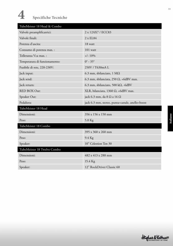
33
TubeMeister 18 Head & Combo
Valvole preamplificatrici: 2 x 12AX7 / ECC83
Valvole finali: 2 x EL84
Potenza d’uscita: 18 watt
Consumo di potenza max. : 101 watt
Tolleranza Vca max. : +/- 10%
Temperatura di funzionamento: 0° - 35°
Fusibile di rete, 220-230V: 250V / T630mA L
Jack input: 6.3 mm, sbilanciato, 1 MΩ
Jack send: 6.3 mm, sbilanciata, 250 Ω, +6dBV max.
Jack return: 6.3 mm, sbilanciato, 500 kΩ, -6dBV
RED BOX Out: XLR, bilanciata, 1360 Ω, +6dBV max.
Speaker Out: jack 6.3 mm, da 8 Ω a 16 Ω
Pedaliera: jack 6.3 mm, stereo, punta=canale, anello=boost
TubeMeister 18 Head
Dimensioni: 356 x 156 x 150 mm
Peso: 5.0 Kg
TubeMeister 18 Combo
Dimensioni: 395 x 360 x 260 mm
Peso: 9.4 Kg
Speaker: 10" Celestion Ten 30
TubeMeister 18 Twelve Combo
Dimensioni: 482 x 413 x 288 mm
Peso: 15.4 Kg
Speaker: 12" RockDriver Classic 60
4 Specifiche Tecniche
ita
lia
no
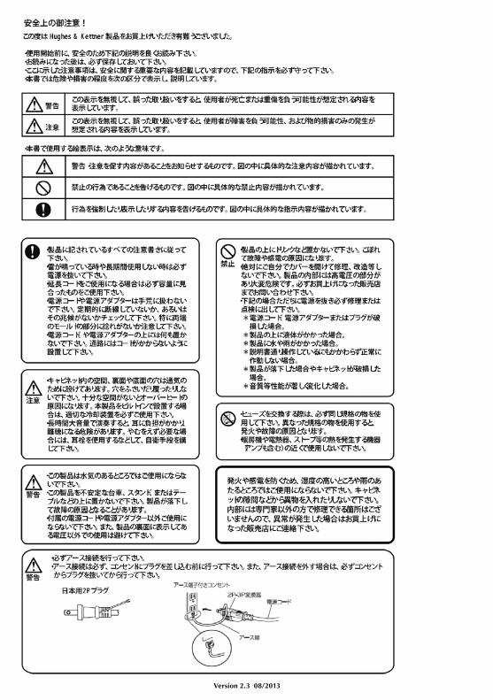
Version 2.3 08/2013
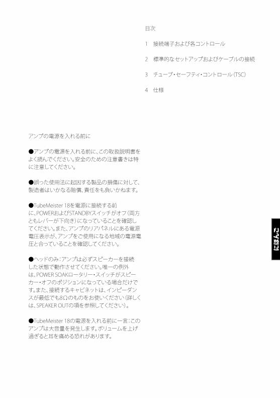
アンプの電源を入れる前に
●アンプの電源を入れる前に、この取扱説明書をよく読んでください。安全のための注意書きは特に注意してください。
●誤った使用法に起因する製品の損傷に対して、製造者はいかなる賠償、責任をも負いかねます。
●TubeMeister 18を電源に接続する前に、POWERおよびSTANDBYスイッチがオフ(両方ともレバーが下向き)になっていることを確認してください。また、アンプのリアパネルにある電源電圧表示が、アンプをご使用になる地域の電源電圧と合っていることを確認してください。
●ヘッドのみ:アンプは必ずスピーカーを接続した状態で動作させてください。唯一の例外は、POWER SOAKロータリー・スイッチがスピーカー・オフのポジションになっている場合だけです。また、接続するキャビネットは、インピーダンスが最低でも8Ωのものをお使いください(詳しくは、SPEAKER OUTの項を参照してください)。
●TubeMeister 18の電源を入れる前に一言:このアンプは大音量を発生します。ボリュームを上げ過ぎると耳を痛める恐れがあります。
目次
1 接続端子および各コントロール
2 標準的なセットアップおよびケーブルの接続
3 チューブ・セーフティ・コントロール(TSC)
4 仕様
にほんご
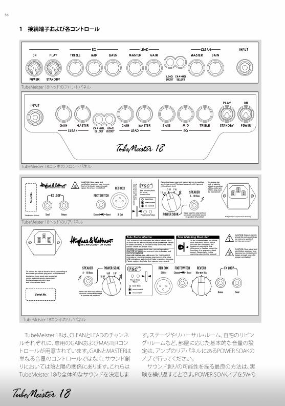
36
1 接続端子および各コントロール
TubeMeister 18は、CLEANとLEADのチャンネルそれぞれに、専用のGAINおよびMASTERコントロールが用意されています。GAINとMASTERは単なる音量のコントロールではなく、サウンド創りにおいては陰と陽の関係にあります。これらはTubeMeister 18の全体的なサウンドを決定しま
す。ステージやリハーサル・ルーム、自宅のリビング・ルームなど、部屋に応じた基本的な音量の設定は、アンプのリアパネルにあるPOWER SOAKのノブで行ってください。 サウンド創りの可能性を探る最良の方法は、実験を繰り返すことです。POWER SOAKノブを5Wの
TubeMeister 18ヘッドのフロントパネル
TubeMeister 18コンボのフロントパネル
TSC™
SendReturn
DI Out8 - 16 Ohms Min MaxChannel Boost5 W 1 W18 W
POWER SOAK RED BOX FOOTSWITCH REVERB FX LOOPSPEAKER
Serial No.
Tube Status Monitor
TubeMeister 18ヘッドのリアパネル
TubeMeister 18コンボのリアパネル
37
位置、他の全てのノブを12時の位置にそれぞれ設定してからGAINとMASTERを調節すれば、プリアンプのパワー・チューブの歪み具合によって様々な色彩のサウンドが得られることがおわかりになるでしょう。
突然の大音量にびっくりしないように、アンプに電源を入れる際にはVOLUMEノブを絞り切っておく習慣を付けましょう。
1.1 フロントパネル
POWER/ONこのスイッチをONの側に切り替えると電源が入ります。アンプのライトが点灯し、チューブが暖まり始めます。
PLAY/STANDBYチューブが暖まるまで30秒ほど待ってからこのスイッチをPLAY側に切り替えると、音が出せる状態になります。演奏を短時間中断する場合には、チューブが動作状態の温度を保つように、このスイッチをSTANDBY側に切り替えて音を切るようにしてください。そうすればチューブも長持ちします。
INPUTシールド・ケーブルでギターとこの入力端子を接続します。
CHANNEL SELECTCLEANとLEADチャンネルを切り替えるスイッチです。LEADチャンネルが選択されると、スイッチの内蔵LEDが青く光ります。フットスイッチを接続すると、フロントパネルのこのスイッチは無効になり、フットスイッチだけが使用可能になりますが、どちらのチャンネルが選択されているかはLED表示で確認できます。
CLEANチャンネルCLEANチャンネルでは、暖かみのあるチューブ・トーンが得られます。ダイナミック・レンジは広大で、濁りのないクリーン・サウンドから野太いクランチ・サウンドまで、多種多様なサウンドが楽しめます。様々なタイプのピックアップに対して驚くほ
ど反応が良く、ギターのボリュームのわずかな設定の変化にも敏感に反映します。
GAINCLEANチャンネルの入力感度を調節します。ギターのピックアップの出力レベルにもよりますが、このノブを12時ぐらいの位置まで回したあたりからアンプがオーバードライブし始めます。このノブは、LEADチャンネルの動作には影響しません。
右段:
MASTER CLEANチャンネルの音量を調節します。LEADチャンネルには影響しません。
LEADチャンネル LEADチャンネルでは、倍音の豊かなチューブ・ディストーション・サウンドが得られます。ゲインには余裕があり、エッジの効いたオーバードライブ・サウンドから舞い上がるようなリード・サウンドまで、多種多様なサウンドが楽しめます。また、ギターのボリュームを絞れば、クリーンなサウンドも得られます。そのため、ギターのピックアップ・セレクターとボリューム・ノブをいじるだけで、サウンドを幅広く変化させることができます。
GAIN チューブ・ディストーションの深さを調節します。ピッキングのニュアンスによってサウンドがいかに大きく変化するかを知っていただくために、このノブを12時の位置に設定し、ギターのボリュームやピックアップ・セレクターの設定を変えたり、アンプのBOOSTスイッチをオンにしたりオフにしたりして、実験してみることをお勧めします。
MASTER LEADチャンネルの音量を調節します。GAINノブを12時の位置に設定して実験する際に、クリーミーなリード・トーンが欲しい時には、パワー・アンプが滑らかなサチュレーションを起こすまでMASTERの設定を上げてください。ヘビーなリフなどを弾くのにエッジの効いたメタル・サウンドが必要な時には、MASTERの設定を控え気味にしてGAINを上げてください。この手のメタル・サウ
にほんご
38
ンドを求める場合、パワー・アンプのサチュレーションはあまり好ましくないからです。
注意:LEADチャンネルのMASTERノブを(反時計方向に)絞り切っても、TubeMeister 18の音を完全にミュートすることはできません。ごく小さな音量でアンプを鳴らしたい場合には、MASTERを絞るよりもむしろ、5Wあるいは1Wモードを選択する方をお勧めします(詳しくは、POWER SOAKの項を参照してください)。
LEAD BOOST オンにすると、スイッチ内蔵のLEDが赤く光り、パンチと非常に長いサスティーンが特徴のモダンなハイ・ゲイン・サウンドが得られます。フットスイッチを接続すると、このスイッチは無効になりますが、動作状態は確認できます。
BASS、MIDおよびTREBLE これらのトーン・コントロールは2つのチャンネルが共有していますが、内部のフィルター回路は別になっており、それぞれのチャンネルで理想的なサウンドが得られるようにチューニングされています。
1.2 リアパネル
FX LOOP シリーズ接続のこのループを使って、外部エフェクターが利用できます。SEND端子とエフェクト・プロセッサーの入力端子、RETURN端子とプロセッサーの出力端子をそれぞれ接続してください。FX LOOPは、6.3mm(1/4インチ)標準プラグをRETURN端子に挿すとオンになります。
参考:SEND端子は、プリアンプの出力を別のパワー・アンプやチューナーなどに送る時にも利用できます。また、RETURN端子は外部音源の出力をTubeMeisterのパワー・アンプに入力する時にも利用できます。POWER SOAKとRED BOXのレコーディング出力を組み合わせれば、考え得るほとんど全ての音源のリアンプやサウンド創りのための機材としても、非常に興味深い利用法が考えられます。
REVERB(コンボのみ) 内蔵のデジタル・スプリング・リバーブの深さを調節します。リバーブ回路は、LEADチャンネルよりもCLEANチャンネルで効果を発揮するように設計されています。
FOOTSWITCH Hughes & Kettner社製FS-2をはじめとする2連のフットスイッチを接続する、ステレオ標準端子です(チップ:CHANNEL SELECT、リング:LEAD BOOST)。ボタン1ではCLEANとLEADのチャンネル切り替え、ボタン2ではLEAD BOOSTのオン/オフがそれぞれ行えます。Hughes & Kettner社製FS-1をはじめとする単独のフットスイッチを接続すれば、チャンネルの切り替えのみが行えます。
参考:この端子を利用して、より洗練されたリモートコントロールも行えます。MIDIスイッチャーもしくはルーパーをここに接続すれば、TubeMeister 18をMIDIでコントロールできるようになります。
RED BOX Hughes & Kettner社が開発したRED BOXは、長年にわたってスピーカー・イミュレーション機能を持ったアナログ方式のギター用DIボックスの業界標準とされてきました。そのRED BOXが、TubeMeister 18のスピーカー出力の信号を、ミキシング・コンソールにそのまま送れるように周波数特性を補正したバランス出力に変換します。RED BOXは、POWER SOAKに入る前のパワー・アンプ出力を取り出します。この出力の信号をPAスピーカーやスタジオのモニターで鳴らすと、ギター・アンプそのもののサウンドに聞こえます。 この出力をミキシング・コンソールに送る時には、マイク用のケーブルを使用してください。コンソールのXLR入力がライン・レベルに設定されていることを確認してください。コンソールにXLR入力端子やライン・レベルの設定が無い場合には、XLR=標準プラグの変換ケーブルが必要です。このケーブルは一般の楽器店で購入できます。なお、CHANNELのMASTERノブの設定はこの出力の信号レベルに直接影響しますが、POWER SOAKモードを選択した場合には影響しません。
39
TSC この機能に関しては、「3 チューブ・セーフティ・コントロール」の項を参照してください。
POWER SOAK TubeMeister 18の出力を調節して基本的な音量を設定します。この機能によって、アンプを自宅のリビング・ルームで鳴らす時でも、近所に迷惑をかけない小さな音量でアンプをフルにドライブしたサウンドが楽しめます。また、ダイレクト・レコーディングのための機能も持っており、スピーカーを鳴らさなくてもミキシング・コンソール経由で正真正銘のチューブ・ドライブ・サウンドが得られます。ミキサーにヘッドフォンを挿せば、昼夜を問わず音を出さずに練習ができます。 POWER SOAKは、単に音量を制御するためだけのものではありません。思い通りのトーンやレスポンスを得るためにも役立ちます。レスポンスが速くて芯のあるモダン・サウンドが必要な時には、POWER SOAKをフル・パワーに設定し、MASTERノブで音量を下げます。いっぽう、パワー・チューブのサチュレーション効果による、粘りのあるクラシカルなロック・サウンドが欲しい時には、POWER SOAKの設定で音量を下げ、MASTERを上げてパワー・チューブに負荷をかけます。
POWER SOAKは次のモードに設定できます:通常のモード=最大出力18Wで動作出力を5Wに抑えたモード出力を1Wに抑えたモードミュート(スピーカー・オフ)=出力0W
ミュートに設定した時には、TubeMeister 18のSPEAKER出力にスピーカーを接続する必要はありません。音を出さずにレコーディングできるように、フル・パワーの信号がRED BOXの出力から取り出せるようになっています。
SPEAKER ギター・アンプ用のスピーカー・キャビネットをこの端子に接続します。ここに1本のケーブルを接続すれば、合成インピーダンスが8~16Ωの範囲であれば、1台でも複数の組み合わせでも、どんなキャビネットでも使用できます。合成インピー
ダンスは、次の式で計算できます。
キャビネット(スピーカー)をシリーズ(直列)接続した場合:R = R1 + R2
たとえば、8Ωのキャビネットを2台シリーズ接続すると、合成インピーダンスは16Ωになります。しかしながら、現代のキャビネットでシリーズ接続になるものはほとんどありません。TubeMeister 112のように、パラレル(並列)接続になるものの方がはるかに一般的です。
キャビネット(スピーカー)をパラレル(並列)接続した場合:R = (R1 x R2) / (R1 + R2)
たとえば、16Ωのキャビネットを2台使用した場合は以下のようになります。
R = (16 x 16) / (16 + 16)R = 256 / 32R = 8
注意:コンボ・アンプでは、すでに内蔵スピーカーのプラグがこの端子に接続されていますが、このプラグを抜けば外部のキャビネットが使用できます。
電源ソケット 同梱の電源ケーブルをこのソケットに接続します。電源ケーブルを壁などのコンセントに接続する前に、コンセントの電圧とアンプの電圧表示が合っていることを確認してください。電源ヒューズのホルダーは、このソケットのすぐ脇にあります。切れたヒューズを交換する際には、必ず指定の交換用ヒューズを使用してください(詳しくは仕様を参照してください)。
にほんご
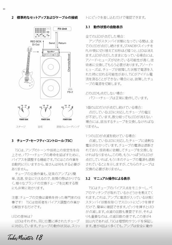
40
2 標準的なセットアップおよびケーブルの接続
FX-Unit
RED BOXDI Out Send
FS-2
Return
Cha
nnel
s/B
oost
ステージ 自宅 深夜のレコーディング
3 チューブ・セーフティ・コントロール(TSC)
TSCは、アンプのトーンや技術上の安定性を向上させ、パワー・チューブの寿命を延ばすために、バイアスを調整する機能です。TSCはこの作業を自動的に行いますから、皆さんは何もする必要がありません。 チューブの交換作業も、従来のアンプより簡単、迅速、安全に行えるので、故障の際ばかりでなく、様々なブランドの交換チューブを比較する際にも非常に助かります。
注意:チューブの交換は資格を持った専門家の仕事です! TSCは技術者をバイアス調整の作業から解放するだけです。
LEDの意味は? LEDはそれぞれ、同じ位置に挿されたチューブに対応しています。チューブの動作状況は、スリッ
トにピックを差し込むだけで確認できます。
3.1 動作状態の自動表示
全てのLEDが点灯した場合: アンプがスタンバイ状態になっている間は、全てのLEDが点灯し続けます。STANDBYスイッチをPLAY側に切り替えて30秒ほど経つと、LEDは消えます。LEDが点灯したままになっている場合には、アノード・ヒューズが切れている可能性が高く、技術者に交換してもらう必要があります。アノード・ヒューズは、チューブが故障した状態で電源を入れた時に切れる可能性があり、TSCがアイドル電流を測ることができない場合には、故障したチューブの電源を切断します。
どのLEDも点灯しない場合: パワー・チューブは正常に動作しています。
1個のLEDだけが点灯し続けている場合: 点灯しているLEDに対応したチューブの電圧が不足しています。数分経ってもLEDが消えない場合には、該当するチューブを交換しなければなりません。
1つのLEDが点滅を続けている場合: 点滅しているLEDに対応したチューブに過剰な電圧がかかっています。チューブの電源は遮断されており、技術者に依頼してチューブを交換しなければなりません。この時、もういっぽうのLEDが点灯していれば、もう1本のチューブの電源も遮断されていることを示しますが、こちらのチューブは交換の必要がありません。
3.2 マニュアル操作による表示
TSCはチューブのバイアス点をモニターし、ペアのマッチングが取れているかどうかを教えてくれます。これは、アンプに電源が入っている状態(スタンバイ状態を除く)でスロットにピックを挿すだけで、簡単に確認できます。ピックを挿すとLEDが点滅します。点滅の回数も重要ですが、それよりも重要なのは、点滅回数の差です。この差が4回以内であれば、TSCは理想的サウンドを保証します。差が4回より多くても、アンプは安全に動作
41
し続けることはできるので、マッチングの取れたペア・チューブと交換する必要はありません。ただし、マッチングの取れたペア・チューブにすれば、より良いトーンが得られるようになります。
4 仕様
TubeMeister 18ヘッドおよびコンボプリアンプ・チューブ: 12AX7 / ECC83 x 2パワー・チューブ: EL 84 x 2出力:18W最大消費電力:101W電源電圧許容範囲: +/-10%動作環境温度:0~+35℃電源ヒューズ、100V用: 250V/T1.25 A LINPUT端子:6.3mm (1/4インチ)標準、アンバランス、1MΩSEND端子:6.3mm (1/4インチ)標準、アンバランス、250Ω、最大+6dBVRETURN端子:6.3mm (1/4インチ)標準、アンバランス、500kΩ、-3dBVRED BOX出力端子:XLR、バランス、1360Ω、最大+6dBVSPEAKER出力端子:6.3mm (1/4インチ)標準、8~16ΩFOOTSWITCH端子:6.3mm (1/4インチ)標準、ステレオ、チップ=CHANNEL、リング=BOOST
TubeMeister 18ヘッド寸法:356 × 156 × 150 mm ( W ×H ×D )重量:5kg
TubeMeister 18コンボ寸法:395 × 360 × 260 mm ( W ×H ×D )重量:9.4kgスピーカー:10インチ、Celestion社製カスタム・スピーカー
TubeMeister 18 Twelve コンボ寸法:482 x 413 x 288 mm ( W ×H ×D )重量:15.4kgスピーカー:12" RockDriver Classic 60
にほんご

42

43

44

45

46

47

Hughes & Kettner
Postfach 1509
66595 St. Wendel
Germany
Tel: +49 (0) 68 51 - 905 0
Fax: +49 (0) 68 51 - 905 103
International Inquiries:
Fax: +49 - 68 51 - 905 200
www.hughes-and-kettner.com
myspace.com/hughesandket tner
facebook.com/hughesandket tner
Copyright 02/2014 by Music & Sales GmbH. Subject to change without notice.
D-2
612b –
02/1
4