Embed Size (px)
Citation preview
2
Manua l de I ns t ruçõesTraduçâo das i ns t ruções o r ig i na i s
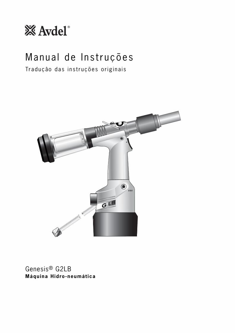
Genesis® G2LBMáquina H idro-neumát ica

3
Regras de segurança 4
EspecificaçõesEspecificações da ferramenta 5Medidas da ferramenta 5
Finalidade de utilizaçãoNumeração de peças 6
Colocação ao serviçoAbastecimento de ar 7Procedimento de operação 7
Conjuntos de pontaAvdelok® e Maxlok® Conjuntos de ponta 8Instruções de montagem Avdelok® 9Instruções de manutenção 9Instruções de montagem Maxlok® 10Instruções de manutenção 10
AcessóriosDeflector de hastes 11Extensão 11
Manutenção da ferramentaDiariamente / Semanalmente 12Dados de segurança da massa Moly-Lithium EP 3753 12Dados de segurança para a massa lubrificanteMolyKote® 55m e MolyKote® 111 13Anualmente 14Kit de manutenção 14Conjunto da cabeça 14-15Conjunto do pistão pneumático 15Conjunto do cursor da válvula 15Gatilho 15
Conjunto geral da ferramenta baseConjunto geral e lista de peças 16-17
PreparaçãoPormenores do óleo 18Dados de segurança para o óleo Hyspin® VG 32 18Kit de preparação 18Procedimento de preparação 19
Diagnóstico de falhas Sintoma, Causa possível e Solução 20
A política da Avdel é de desenvolvimento e melhoramento contínuos de produto e reservámos o direito de alterar as especificações de qualquer produto sem aviso prévio.
GarantiaAs ferramentas de instalação Avdel possuem uma garantia de 12 meses contradefeitos causados por materiais ou mão-de-obra defeituosa, o período de garantiacomeça a partir da data de entrega confirmada por factura ou aviso de entrega.
A garantia aplica-se ao utilizador/comprador quando vendida através de um ponto devenda autorizado, e apenas quando for utilizada para os fins para que foi destinada. A garantia será invalidada se a ferramenta de instalação não for reparada, mantida e operada de acordo com as instruções incluídas nos Manuais de Instruções eManutenção.
Em caso de defeito ou falha, e à sua inteira discrição, a Avdel só se compromete areparar ou a substituir componentes defeituosos.
Í nd ice

4
Regras de segurança
1 Utilize apenas para a finalidade para que foi concebida.
2 Utilize apenas equipamento recomendado e fornecido pela Avdel UK Limited com esta ferramenta/máquina.
3 Qualquer modificação efectuada pelo cliente à ferramenta/máquina, conjuntos de ponta, acessórios ou qualquer equipamento
fornecido por Avdel UK Limited ou seus representantes, será da inteira responsabilidade do cliente. Avdel UK Limited terá todo
o prazer em aconselhar sobre qualquer modificação proposta.
4 A ferramenta/máquina terá de ser mantida sempre em condição de segurança e inspeccionada a intervalos regulares quanto a
danos e operada por pessoal competente e treinado. Qualquer procedimento de desmontagem será realizado apenas por
pessoal formado em procedimentos Avdel UK Limited. Não desmonte a ferramenta/máquina sem primeiro consultar as
instruções de manutenção. Contacte a Avdel UK Limited com os seus requisitos de formação.
5 A ferramenta/máquina deverá ser sempre operada de acordo com a legislação de Saúde e Segurança pertinente. No R.U.
aplica-se a norma de 1974 “Saúde e Segurança no Trabalho etc.”. Quaisquer perguntas que digam respeito à operação
correcta da ferramenta/máquina e segurança do operador deverão ser feitas directamente à Avdel UK Limited.
6 As precauções a ter em conta ao utilizar esta ferramenta/máquina terão de ser explicadas pelo cliente a todos os operadores.
7 Desligue sempre a linha de ar da entrada da ferramenta/máquina antes de tentar ajustar, montar ou remover o conjunto de
ponta.
8 Não opere uma ferramenta/máquina que esteja apontada na direcção de pessoas ou do operador.
9 Adopte sempre uma posição equilibrada e firme antes de operar a ferramenta/máquina.
10 Certifique-se de que os orifícios de ventilação não estão bloqueados ou tapados.
11 A pressão de funcionamento não deverá exceder as 7 bar.
12 Não opere a ferramenta sem o equipamento de ponta estar em posição a não ser que sejam dadas instruções em contrário.
13 Deve-se ter cuidado para assegurar que não se deixa que as hastes utilizadas criem um risco.
14 Montando um captador de hastes na ferramenta, é necessário esvaziá-lo quando estiver meio cheio.
15 No caso de se montar um deflector de hastes na ferramenta G4, este deve ser rodado até a abertura ficar apontada na
direcção contrária do operador e de outras pessoas na proximidade.
16 Ao utilizar a ferramenta, é necessário o uso de óculos de protecção, tanto pelo operador como pelas pessoas que se
encontram na proximidade para proteger contra a projecção de elementos de fixação, no caso de um elemento de fixação ser
colocado "no ar". Recomendamos a utilização de luvas se existirem arestas ou cantos vivos na aplicação.
17 Tenha cuidado para evitar que roupas soltas, gravatas, cabelo comprido, trapos de limpeza etc. sejam apanhados pelas partes
móveis da ferramenta, esta deverá ser mantida limpa e seca para a melhor agarração possível.
18 Ao transportar a ferramenta de lugar para lugar mantenha as mãos afastadas do gatilho/alavanca para evitar o arranque
inadvertido.
19 Contacto excessivo com o óleo de fluido hidráulico deverá ser evitado. Para minimizar a possibilidade de irritações da pele,
deverá ter cuidado para lavar muito bem.
20 Os dados C.O.S.H.H. para todos os óleos hidráulicos e lubrificantes estão disponíveis quando solicitado do fornecedor local daferramenta.
Este manual de instruções tem de ser lido pela pessoa que irá instalar, operar ou fazer a manutenção destaferramenta prestando atenção especial às seguintes regras de segurança.
5
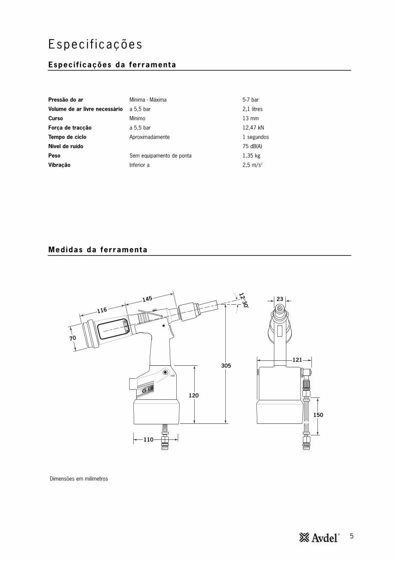
Dimensões em milímetros
2
23
121
110
120
150
305
145
116
70
2
12°30'
Pressão do ar Mínima - Máxima 5-7 bar
Volume de ar livre necessário a 5,5 bar 2,1 litres
Curso Mínimo 13 mm
Força de tracção a 5,5 bar 12,47 kN
Tempo de ciclo Aproximadamente 1 segundos
Nível de ruído 75 dB(A)
Peso Sem equipamento de ponta 1,35 kg
Vibração Inferior a 2,5 m/s2
Espec i f i caçõesEspec i f icações da ferramenta
Medidas da ferramenta
6
F ina l idade de u t i l i zação
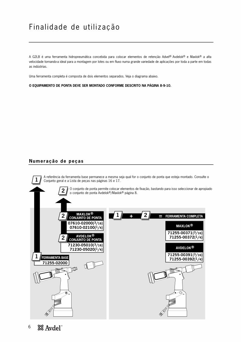
A G2LB é uma ferramenta hidropneumática concebida para colocar elementos de retenção Advel® Avdelok® e Maxlok® a altavelocidade tornando-a ideal para a montagem por lotes ou em fluxo numa grande variedade de aplicações por toda a parte em todasas indústrias.
Uma ferramenta completa é composta de dois elementos separados. Veja o diagrama abaixo.
O EQUIPAMENTO DE PONTA DEVE SER MONTADO CONFORME DESCRITO NA PÁGINA 8-9-10.
AVDELOK®
71255-02000
71230-05010(3/16)71230-05020(1/4)
1
1
2
+ =1 2
2
MAXLOK®
07610-02000(3/16)07610-02100(1/4)
2
AVDELOK®
71255-00391(3/16)71255-00392(1/4)
MAXLOK®
71255-00371(3/16)71255-00372(1/4)
CONJUNTO DE PONTA
CONJUNTO DE PONTA
FERRAMENTA BASE
FERRAMENTA COMPLETA
A referência da ferramenta base permanece a mesma seja qual for o conjunto de ponta que esteja montado. Consulte o Conjunto geral e a Lista de peças nas páginas 16 e 17.
O conjunto de ponta permite colocar elementos de fixação, bastando para isso seleccionar de apropiadoo conjunto de ponta Avdelok®/Maxlok® página 8.
Numeração de peças
7
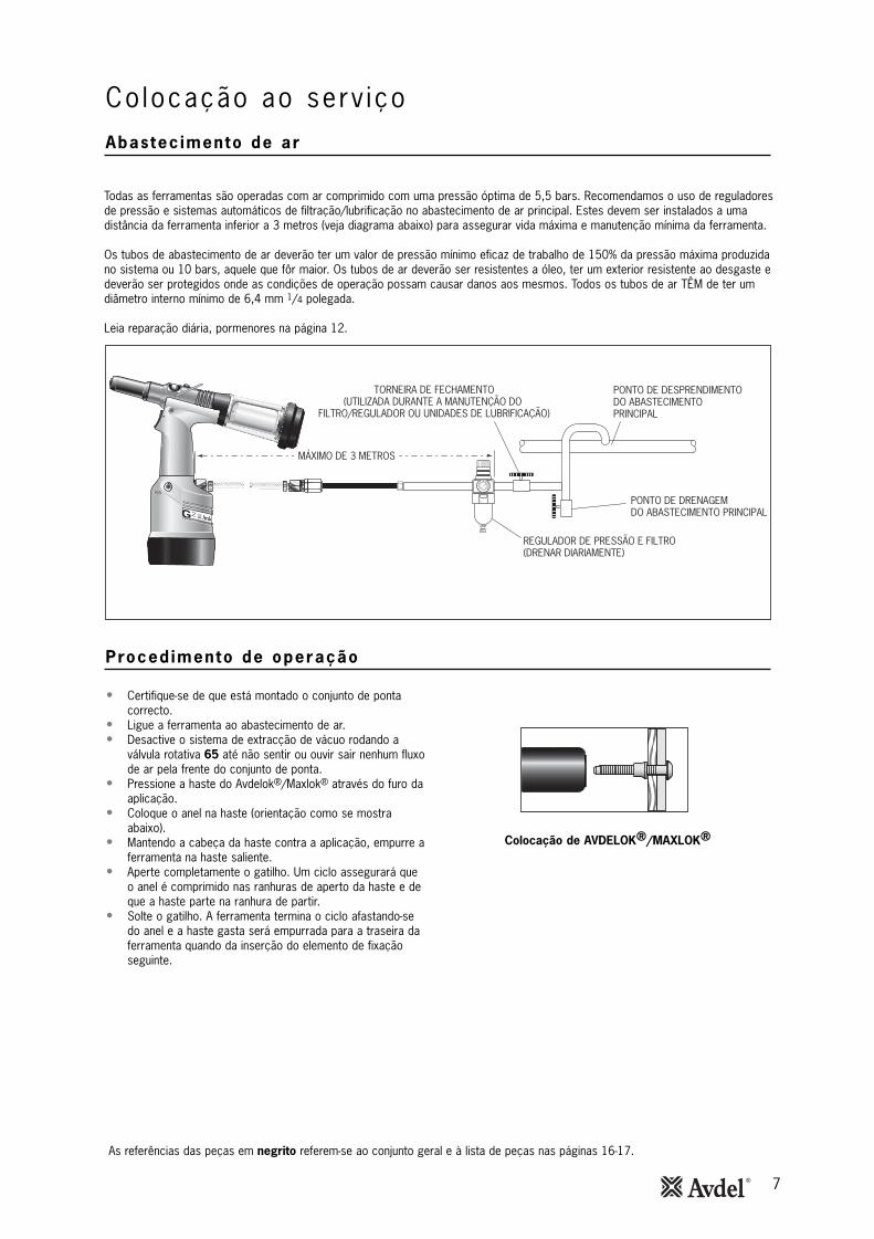
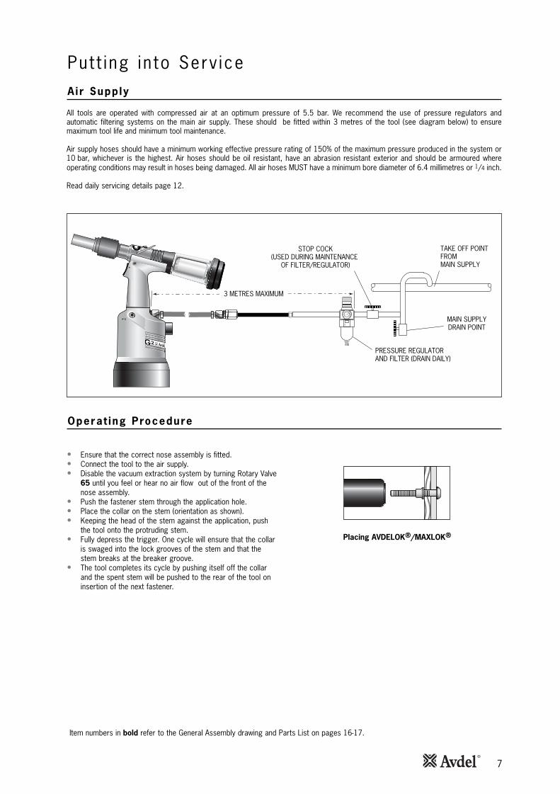
Todas as ferramentas são operadas com ar comprimido com uma pressão óptima de 5,5 bars. Recomendamos o uso de reguladoresde pressão e sistemas automáticos de filtração/lubrificação no abastecimento de ar principal. Estes devem ser instalados a umadistância da ferramenta inferior a 3 metros (veja diagrama abaixo) para assegurar vida máxima e manutenção mínima da ferramenta.
Os tubos de abastecimento de ar deverão ter um valor de pressão mínimo eficaz de trabalho de 150% da pressão máxima produzidano sistema ou 10 bars, aquele que fôr maior. Os tubos de ar deverão ser resistentes a óleo, ter um exterior resistente ao desgaste edeverão ser protegidos onde as condições de operação possam causar danos aos mesmos. Todos os tubos de ar TÊM de ter umdiâmetro interno mínimo de 6,4 mm 1/4 polegada.
Leia reparação diária, pormenores na página 12.
864
20
10121416
2
PONTO DE DESPRENDIMENTO DO ABASTECIMENTO PRINCIPAL
TORNEIRA DE FECHAMENTO(UTILIZADA DURANTE A MANUTENÇÃO DO
FILTRO/REGULADOR OU UNIDADES DE LUBRIFICAÇÃO)
PONTO DE DRENAGEM DO ABASTECIMENTO PRINCIPAL
REGULADOR DE PRESSÃO E FILTRO (DRENAR DIARIAMENTE)
MÁXIMO DE 3 METROS
• Certifique-se de que está montado o conjunto de pontacorrecto.
• Ligue a ferramenta ao abastecimento de ar.• Desactive o sistema de extracção de vácuo rodando a
válvula rotativa 65 até não sentir ou ouvir sair nenhum fluxode ar pela frente do conjunto de ponta.
• Pressione a haste do Avdelok®/Maxlok® através do furo daaplicação.
• Coloque o anel na haste (orientação como se mostraabaixo).
• Mantendo a cabeça da haste contra a aplicação, empurre aferramenta na haste saliente.
• Aperte completamente o gatilho. Um ciclo assegurará queo anel é comprimido nas ranhuras de aperto da haste e deque a haste parte na ranhura de partir.
• Solte o gatilho. A ferramenta termina o ciclo afastando-sedo anel e a haste gasta será empurrada para a traseira daferramenta quando da inserção do elemento de fixaçãoseguinte.
As referências das peças em negrito referem-se ao conjunto geral e à lista de peças nas páginas 16-17.
Co locação ao serv içoAbastec imento de ar
Proced imento de operação
Colocação de AVDELOK®/MAXLOK®
8
Con jun tos de ponta
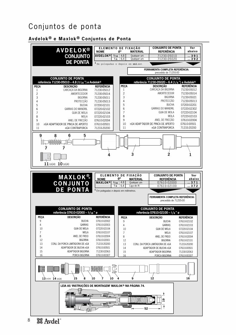
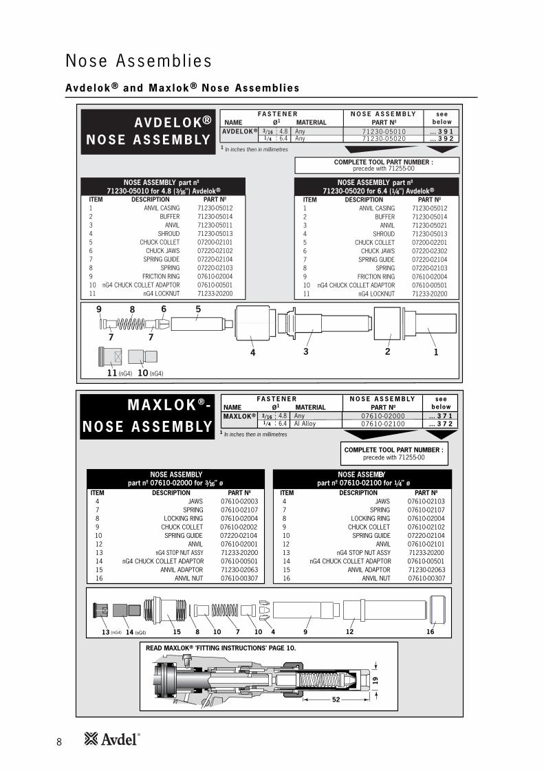
Avdelok® e Maxlok® Conjuntos de Ponta
CONJUNTO DE PONTA 1 Em polegadas e depois em mil�metros.
PEÇA DESCRIÇÃO REFERÊNCIA1 71230-050122 71230-050143 71230-050114 71230-050135 07200-021016 07220-021027 07220-021048 07220-021039 07610-0200410 nG4 ADAPTADOR DE PINCA DE APERTO 07610-0050111 nG4 CONTRAPORCA 71233-20200
PEÇA DESCRIÇÃO REFERÊNCIA1 71230-050122 71230-050143 71230-050214 71230-050135 07200-022016 07220-023027 07220-021048 07220-021039 07610-0200410 nG4 ADAPTADOR DE PINCA DE APERTO 07610-0050111 nG4 CONTRAPORCA 71233-20200
3/161/4
71230-0501071230-05020
4.86.4
… 3 9 1… 3 9 2
FERRAMENTA COMPLETA REFERÊNCIA: precedido de 71255-00
Qualquer umQualquer um
E L E M E N T O D E F I X A Ç Ã OMATERIALØ1
CONJUNTO DE PONTA VerabaixoREFERÊNCIA NOME
referência 71230-05010 – 4.8 ( 3/16 ") ø Avdelok®CONJUNTO DE PONTA
referência 71230-05020 – 6.4 ( 1/4 ") ø Avdelok®CONJUNTO DE PONTA
CARCAÇA DA BIGORNAAMORTECEDOR
BIGORNAPROTECÇÃO
BUCHAGARRAS DO MANDRIL
GUIA DE MOLAMOLA
ANEL DE FRICÇÃO
CARCAÇA DA BIGORNAAMORTECEDOR
BIGORNAPROTECÇÃO
BUCHAGARRAS DO MANDRIL
GUIA DE MOLAMOLA
ANEL DE FRICÇÃO
AV D E L O K ®AVDELOK®
(nG4) (nG4)
2 1
1
3
6 5
4
8
7
9
7
11 10
M A X L O K ®
C O N J U N T OD E P O N TA
PEÇA DESCRIÇÃO REFERÊNCIA9 07610-020024 07610-0200310 07220-021047 07610-021078 07610-0200412 07610-0200113 CONJ. DA PORCA LIMITADORA DE nG414 ADAPTADOR DE BUCHA nG415 ADAPTADOR BIGORNA16 PORCA BIGORNA
71233-2020007610-0050171230-0206307610-00307
PEÇA DESCRIÇÃO REFERÊNCIA9 07610-021024 07610-0210310 07220-021047 07610-021078 07610-0200412 07610-0210113 CONJ. DA PORCA LIMITADORA DE nG414 ADAPTADOR DE BUCHA nG415 ADAPTADOR BIGORNA16 PORCA BIGORNA
71233-2020007610-0050171230-0206307610-00307
Em polegadas e depois em milímetros.
Qualquer umLiga de Al
FERRAMENTA COMPLETA REFERÊNCIA: precedido de 71255-00
E L E M E N T O D E F I X A Ç Ã OMATERIAL
CONJUNTO DE PONTA VerabaixoREFERÊNCIA NOME
referência 07610-02000 – 3/16 " ø referência 07610-02100 – 1/4 " øCONJUNTO DE PONTA CONJUNTO DE PONTA
BUCHAGARRAS
GUIA DE MOLAMOLA
ANEL DE FREIOBIGORNA
BUCHAGARRAS
GUIA DE MOLAMOLA
ANEL DE FREIOBIGORNA
LEIA AS ‘INSTRUÇÕES DE MONTAGEM’ MAXLOK® NA PÁGINA 74.
-
1
Ø1
3/161/4
07610-0200007610-02100
4.86.4
MAXLOK® … 3 7 1… 3 7 2
52
19
1615 7 10 9410 13 14 (nG4) 128 (nG4)
Ins t ruções de montagem Avde lok®
9
Con jun tos de ponta
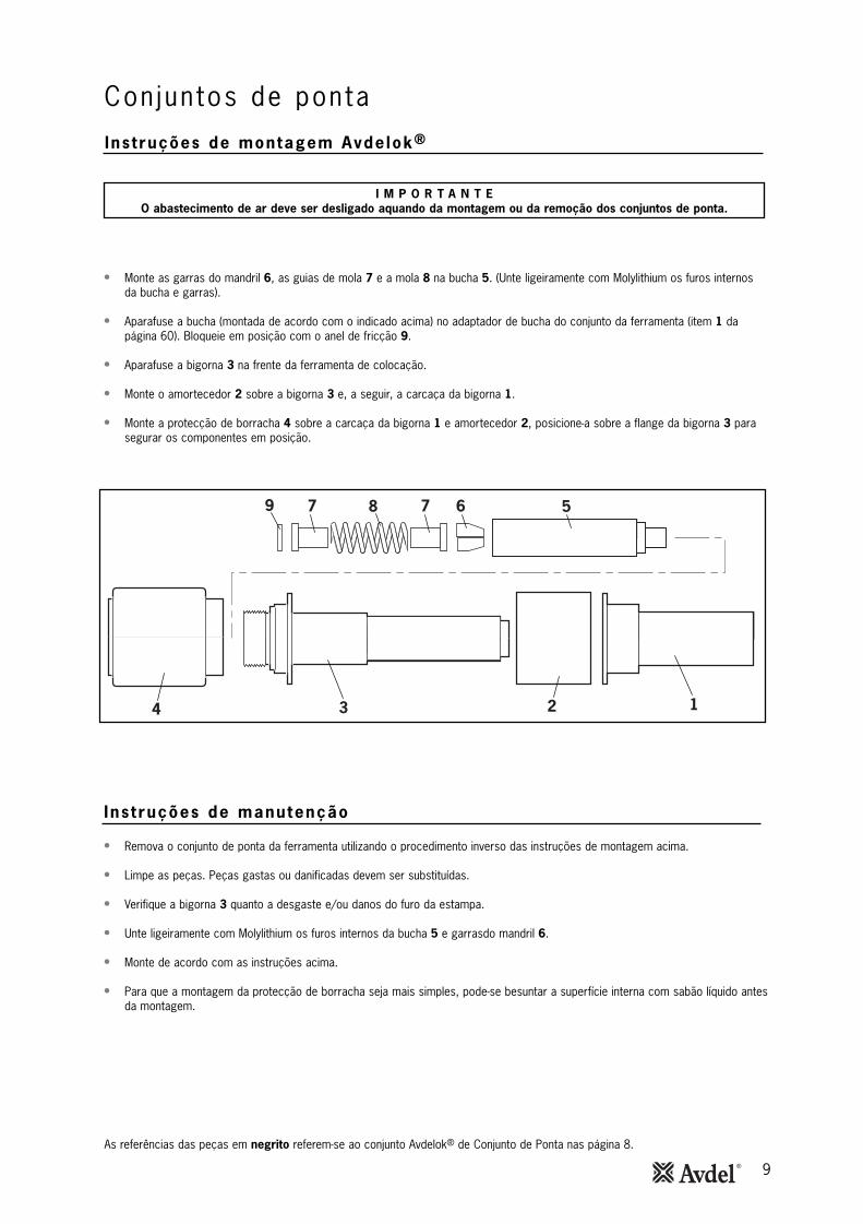
• Monte as garras do mandril 6, as guias de mola 7 e a mola 8 na bucha 5. (Unte ligeiramente com Molylithium os furos internosda bucha e garras).
• Aparafuse a bucha (montada de acordo com o indicado acima) no adaptador de bucha do conjunto da ferramenta (item 1 dapágina 60). Bloqueie em posição com o anel de fricção 9.
• Aparafuse a bigorna 3 na frente da ferramenta de colocação.
• Monte o amortecedor 2 sobre a bigorna 3 e, a seguir, a carcaça da bigorna 1.
• Monte a protecção de borracha 4 sobre a carcaça da bigorna 1 e amortecedor 2, posicione-a sobre a flange da bigorna 3 parasegurar os componentes em posição.
Ins t ruções de manutenção
• Remova o conjunto de ponta da ferramenta utilizando o procedimento inverso das instruções de montagem acima.
• Limpe as peças. Peças gastas ou danificadas devem ser substituídas.
• Verifique a bigorna 3 quanto a desgaste e/ou danos do furo da estampa.
• Unte ligeiramente com Molylithium os furos internos da bucha 5 e garrasdo mandril 6.
• Monte de acordo com as instruções acima.
• Para que a montagem da protecção de borracha seja mais simples, pode-se besuntar a superfície interna com sabão líquido antesda montagem.
I M P O R T A N T EO abastecimento de ar deve ser desligado aquando da montagem ou da remoção dos conjuntos de ponta.
2 1
1
3
6 5
4
879 7
As referências das peças em negrito referem-se ao conjunto Avdelok® de Conjunto de Ponta nas página 8.
10
Ins t ruções de montagem Maxlok®
Con jun tos de ponta
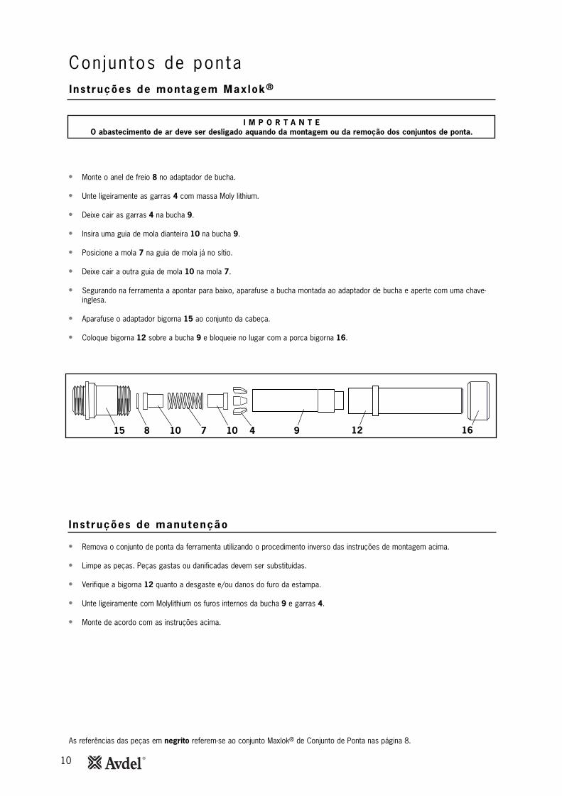
• Monte o anel de freio 8 no adaptador de bucha.
• Unte ligeiramente as garras 4 com massa Moly lithium.
• Deixe cair as garras 4 na bucha 9.
• Insira uma guia de mola dianteira 10 na bucha 9.
• Posicione a mola 7 na guia de mola já no sítio.
• Deixe cair a outra guia de mola 10 na mola 7.
• Segurando na ferramenta a apontar para baixo, aparafuse a bucha montada ao adaptador de bucha e aperte com uma chave-inglesa.
• Aparafuse o adaptador bigorna 15 ao conjunto da cabeça.
• Coloque bigorna 12 sobre a bucha 9 e bloqueie no lugar com a porca bigorna 16.
Ins t ruções de manutenção
• Remova o conjunto de ponta da ferramenta utilizando o procedimento inverso das instruções de montagem acima.
• Limpe as peças. Peças gastas ou danificadas devem ser substituídas.
• Verifique a bigorna 12 quanto a desgaste e/ou danos do furo da estampa.
• Unte ligeiramente com Molylithium os furos internos da bucha 9 e garras 4.
• Monte de acordo com as instruções acima.
I M P O R T A N T EO abastecimento de ar deve ser desligado aquando da montagem ou da remoção dos conjuntos de ponta.
1615 7 10 9410 128
As referências das peças em negrito referem-se ao conjunto Maxlok® de Conjunto de Ponta nas página 8.
11
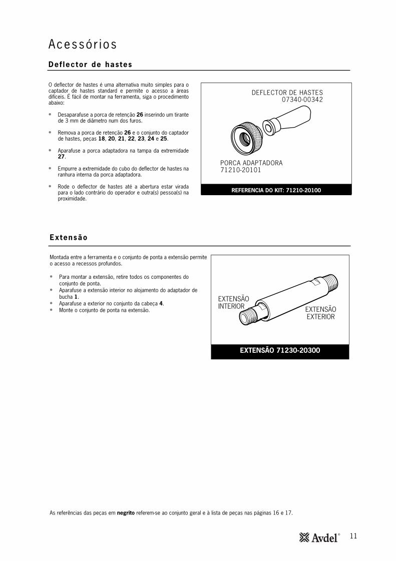
Acessór iosDef lector de hastes
PORCA ADAPTADORA71210-20101
DEFLECTOR DE HASTES07340-00342
O deflector de hastes é uma alternativa muito simples para ocaptador de hastes standard e permite o acesso a áreasdifíceis. É fácil de montar na ferramenta, siga o procedimentoabaixo:
• Desaparafuse a porca de retenção 26 inserindo um tirantede 3 mm de diâmetro num dos furos.
• Remova a porca de retenção 26 e o conjunto do captadorde hastes, peças 18, 20, 21, 22, 23, 24 e 25.
• Aparafuse a porca adaptadora na tampa da extremidade27.
• Empurre a extremidade do cubo do deflector de hastes naranhura interna da porca adaptadora.
• Rode o deflector de hastes até a abertura estar viradapara o lado contrário do operador e outra(s) pessoa(s) naproximidade.
REFERENCIA DO KIT: 71210-20100
As referências das peças em negrito referem-se ao conjunto geral e à lista de peças nas páginas 16 e 17.
EXTENSÃOINTERIOR EXTENSÃO
EXTERIOR
Montada entre a ferramenta e o conjunto de ponta a extensão permiteo acesso a recessos profundos.
• Para montar a extensão, retire todos os componentes doconjunto de ponta.
• Aparafuse a extensão interior no alojamento do adaptador debucha 1.
• Aparafuse a exterior no conjunto da cabeça 4.• Monte o conjunto de ponta na extensão.
Extensão
EXTENSÃO 71230-20300
12
• Verifique se existem fugas de ar. Se danificados, os tubos e os acoplamentos deverão ser substituídos.
• Se não houver filtro no regulador de pressão, sangre a linha de ar para a limpar de sujidade acumulada ou água antes de ligar otubo de ar à ferramenta. Se houver um filtro drene-o.
• Verifique que o conjunto de ponta é o correcto para o elemento de fixação a colocar.
• Verifique que o curso da ferramenta está de acordo com a especificação mínima (página 5). O último passo do Procedimento dapreparação na página 19, explica como medir o curso.
• Se a extracção de vácuo estiver ‘ON’ (Ligada), é preciso montar um captador ou um deflector de hastes na ferramenta. Seestiver ‘OFF’ (Desligado) é preciso montar uma tampa de segurança. Veja ao lado ‘Ejector lateral’.
• É necessário montar um colector ou um deflector de hastes na ferramenta.
• Verifique que a válvula rotativa 65 está DESLIGADA.
• Desmonte e limpe o conjunto de ponta prestando atenção especial às garras. Antes de montar, lubrifique com massa Moly-Lithium EP 3753.
• Verifique se existem fugas de ar.
A massa pode ser encomendada como um único item, a referência está indicada no kit de manutenção na página 13.
Primeiros socorros
PELE:
Uma vez que a massa é resistente à água, é melhor retirá-la com uma solução de limpeza de pele emulsionante aprovada.
INGESTÃO:
Certifique-se de que a pessoa bebe 30 ml de leite de magnésia, de preferência numa chávena de leite.
OLHOS:
Irritante mas não perigoso. Lave com água e consulte o médico.
Incêndio
PONTO DE INFLAMAÇÃO: Acima de 220°C.
Não classificado de inflamável.
Meios de extinção adequados: CO2, Halon ou pulverização a água se aplicada por um operador com experiência.
Ambiental
Coloque na sucata para queimar ou descarte num lugar aprovado.
Manuseamento
Use creme de protecção ou luvas resistentes ao óleo.
Armazenamento
Longe de fontes de calor e agentes oxidantes.
As referências das peças em negrito referem-se ao conjunto geral e à lista de peças nas páginas 16-17.
I M P O R T A N T E
Leia as instruções de segurança na página 4.O empregador é responsável por assegurar que as instruções de manutenção da ferramenta são dadas ao pessoal
apropriado. O operador não deverá estar envolvido na manutenção ou reparação da ferramenta a não ser que esteja devidamente formado.
A ferramenta deverá ser examinada periodicamente para danos e funcionamento defeituoso.
Manutenção da fer ramenta
Diar iamente
Semanalmente
Dados de segurança da massa Moly -L i th ium EP 3753
13
Manutenção da fer ramentaDados de segurança para a massa lubr i f icante MolyKote® 55m
Dados de segurança para a massa lubr i f icante MolyKote® 111
rimeiros socorros
PELE:
Lavar com água. Limpar.
INGESTÃO:
Primeiros socorros não deverão ser necessários.
OLHOS:
Lavar com água.
Incêndio
PONTO DE INFLAMAÇÃO: Superior a 101,1 °C. (recipiente fechado)
Propriedades explosivas: Não
Meios de extinção adequados: Espuma de dióxido de carbono, pó seco ou pulverização fina de água.
É possível utilizar água para arrefecer os recipientes expostos ao fogo.
Meio ambiente
Não permitir a infiltração de grandes quantidades em esgotos ou água à superfície.
Métodos de limpeza: Recolher e colocar em recipiente adequado equipado com tampa. O produto derramado produz umasuperfície extremamente escorregadia.
Nocivo para os organismos aquáticos e pode causar efeitos nefastos a longo prazo no ambiente aquático. No entanto, devido àforma física e à insolubilidade na água do produto a biodisponibilidade é desprezável.
Manuseamento
Recomendada ventilação geral. Evitar contacto com os olhos e a pele.
Armazenamento
Não armazenar com agentes de oxidação. Manter o recipiente fechado e armazenar afastado de água e humidade.
Primeiros socorros
PELE:
Primeiros socorros não deverão ser necessários.
INGESTÃO:
Primeiros socorros não deverão ser necessários.
OLHOS:
Primeiros socorros não deverão ser necessários.
Inalação:
Primeiros socorros não deverão ser necessários.
Incêndio
PONTO DE INFLAMAÇÃO: Superior a 101,1 °C. (recipiente fechado)
Propriedades explosivas: Não
Meios de extinção adequados: Espuma de dióxido de carbono, pó seco ou pulverização fina de água.
É possível utilizar água para arrefecer os recipientes expostos ao fogo.
Meio ambiente
Não se antecipam efeitos adversos.
Manuseamento
Recomendada ventilação geral. Evitar o contacto com os olhos.
Armazenamento
Não armazenar com agentes de oxidação. Manter o recipiente fechado e armazenar afastado de água e humidade.
14
Salvo instruções em contrário, a linha de ar deverá ser desconectada antes de se proceder à desmontagem ou a quaisquerreparações.
Recomenda-se que qualquer operação de desmontagem seja feita em condições limpas.
Antes de prosseguir com a desmontagem, esvazie o óleo da ferramenta seguindo os três primeiros passos do ‘Procedimento depreparação’ na página 19.
Antes de desmontar a ferramenta, é necessário remover o equipamento de ponta. Para obter instruções, consulte a secção deequipamento de ponta nas páginas 8, 9 a 10.
Para uma reparação completa da ferramenta, aconselhámos que proceda à desmontagem dos subconjuntos pela ordem indicada.
Após qualquer desmontagem NÃO SE ESQUEÇA de preparar a ferramenta e de montar um conjunto de ponta ou de cabeça rotativaadequado.
I M P O R T A N T E
Leia as instruções de segurança na página 4.O empregador é responsável por assegurar que as instruções de manutenção da ferramenta são dadas ao pessoal
apropriado. O operador não deverá estar envolvido na manutenção ou reparação da ferramenta a não ser que esteja devidamente formado.
A ferramenta deverá ser examinada periodicamente para danos e funcionamento defeituoso.
* peças incluídas no kit de manutenção.As referências das peças em negrito referem-se ao conjunto geral e à lista de peças nas páginas 16-17.
• Desaparafuse a porca de retenção 26 e puxe para retirar o conjunto de ponta, peças 15, (72) 18, 19, 20, 21, 22, 23, 24,25 e ‘O’ ring 19.
• Utilizando a chave-inglesa em ‘T’* remova a tampa da extremidade 27 (73) juntamente com o vedante 17, o ‘O’ ring 16 e a junta delábio 28.
• Afrouxe a contraporca 3 com a chave inglesa* e desaparafuse o adaptador de bucha 1.
• Remova a contraporca 3 juntamente com os ‘O’ rings 49 e 50.
• Retire o parafuso de sangria 9 e o vedante unido 10.
• Empurre o pistão da cabeça 7 para a traseira e para fora do conjunto da cabeça 4 tendo o cuidado para não danificar odiâmetro interno do cilindro.
• Remova o retentor de vedante 30. Empurre a junta de lábio 8 para a traseira e para fora do conjunto da cabeça 4 tendonovamente o cuidado para não danificar o diâmetro interno do cilindro.
• Remova o invólucro vedante 5 e a junta de lábio 67.
07900-00667 07900-00692 07900-00670 07900-00672 07900-00706 07900-00684 07900-00685 07900-00351 07900-00469 07900-0015807900-0022407900-00734
07900-0016407900-0000807900-0001207900-0001507900-0068607900-0067707900-0069807900-0070007992-0002007992-0007507900-00755
REFERÊNCIA DESCRIÇÃOREFERÊNCIA DESCRIÇÃO
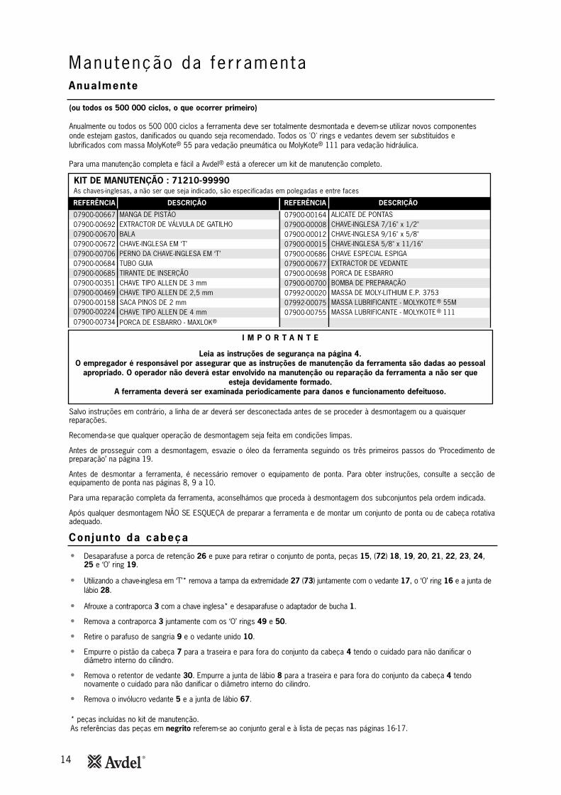
KIT DE MANUTENÇÃO : 71210-99990 As chaves-inglesas, a não ser que seja indicado, são especificadas em polegadas e entre faces
ALICATE DE PONTASCHAVE-INGLESA 7/16" x 1/2"CHAVE-INGLESA 9/16" x 5/8"CHAVE-INGLESA 5/8" x 11/16"CHAVE ESPECIAL ESPIGAEXTRACTOR DE VEDANTEPORCA DE ESBARRO
PORCA DE ESBARRO - MAXLOK®
BOMBA DE PREPARAÇÃOMASSA DE MOLY-LITHIUM E.P. 3753MASSA LUBRIFICANTE - MOLYKOTE ® 55MMASSA LUBRIFICANTE - MOLYKOTE ® 111
MANGA DE PISTÃOEXTRACTOR DE VÁLVULA DE GATILHOBALA CHAVE-INGLESA EM ‘T’PERNO DA CHAVE-INGLESA EM ‘T’TUBO GUIATIRANTE DE INSERÇÃOCHAVE TIPO ALLEN DE 3 mmCHAVE TIPO ALLEN DE 2,5 mmSACA PINOS DE 2 mmCHAVE TIPO ALLEN DE 4 mm
(ou todos os 500 000 ciclos, o que ocorrer primeiro)
Anualmente ou todos os 500 000 ciclos a ferramenta deve ser totalmente desmontada e devem-se utilizar novos componentesonde estejam gastos, danificados ou quando seja recomendado. Todos os 'O' rings e vedantes devem ser substituídos elubrificados com massa MolyKote® 55 para vedação pneumática ou MolyKote® 111 para vedação hidráulica.
Para uma manutenção completa e fácil a Avdel® está a oferecer um kit de manutenção completo.
Manutenção da fer ramentaAnualmente
Conjunto da cabeça
15
Faça a montagem pela ordem inversa da desmontagem tendo em atenção os pontos seguintes:
• Coloque a junta de lábio 8 no tirante de inserção* assegurando orientação correcta. Empurre o tubo guia* na cabeça daferramenta e empurre o tirante de inserção* com o vedante em posição através do tubo guia*. Puxe retirando o tirante deinserção* e a seguir o tubo guia.
• Deixe cair o retentor de vedante 30 contra a junta de lábio 8 flange grande primeiro.
• Monte a junta de lábios 11 e o 'O' ring 13 (2 unidades) no pistão da cabeça 7.
• Lubrifique o interior do cilindro e coloque a manga do pistão* na traseira do conjunto da cabeça 4. Deslize a bala* na parteroscada do pistão 7 e empurre o pistão com os vedantes através da manga do pistão* até ao máximo que ele pode ir. Deslize abala* para fora do pistão e remova a manga do pistão.
• Monte o invólucro vedante 5 e a junta de lábio 67.
• Aperte completamente o alojamento alargador de garras 1 ao pistão da cabeça 7 ANTES de apertar a contraporca 3 contra omesmo.
• Utilize Loctite® 932 ao montar a porca de retenção 26.
• Remova o conjunto da válvula 'ON/OFF' 60.
• Prenda com grampo o corpo da ferramenta invertida ENTRE AS SALIÊNCIAS DA ADMISSÃO DE AR num torno com maxilaresprotegidos.
• Retire o resguardo de borracha 80.
• Utilizando a chave de cavilhas* desaparafuse a tampa da base 40.
• Desaparafuse as contraporcas 76 (2 unidades) e retire a placa da base 77.
• Retire a camisa do cilindro 45 juntamente com as anilhas de vedação 75 (2 unidades) e os 'O' rings 78 (2 unidades).
• Retire o conjunto do pistão pneumático 42 juntamente com o 'O' ring 39, a junta de lábios 41 (3 unidades) e o anel guia 35.
• Encaixe o extractor de vedantes* no conjunto de vedação 34 e remova o conjunto de vedação do tubo intensificador do conjunto dacabeça 4.
Monte pela ordem inversa.
• Remova o conjunto do pistão pneumático 42 e o conjunto vedante 34 como descrito acima.
• Utilizando a chave em ‘T’ e a espiga de chave em ‘T’, desaperte a porca de aperto 36 e remova juntamente com a chapa deaperto 63, o conjunto de tubo de transferência 44, o ‘O’ ring 6, a haste da válvula 43 e as almofadas silenciadoras 62.
• Solte a ferramenta do torno e separe o corpo 38 com o 'O' ring 31 do conjunto do punho 32.
• Remova o 'O' ring 33 do tubo intensificador e puxe o conjunto da cabeça 4 do conjunto do punho 32.
• Retire puxando a sede da válvula 64 com os dois 'O' rings 6.
• Retire puxando todos os componentes do conjunto do cursor da válvula 54.
• Finalmente remova o 'O' ring 59 do encaixe do punho.
Monte pela ordem inversa observando os seguintes pontos:
• Verifique que a abertura central da sede da válvula 64 está virada para cima.
• Utilize Loctite® 243 quando da montagem da porca de fixação 36, binário 14,91 Nm..
• Utilizando o saca pinos de 2 mm de diâmetro*, accione o pino do gatilho 48 para fora e retire elevando o gatilho 47.
• Desaparafuse a válvula do gatilho 46 utilizando o extractor* de válvula de gatilho.
Faça a montagem pela ordem inversa da desmontagem.
I M P O R T A N T E
Verifique a ferramenta para reparação diária e semanal.A preparação é SEMPRE necessária após desmontagem e antes de se operar a ferramenta.
* peças incluídas no kit de manutenção. Para a lista completa veja a página 14. As referências das peças em negrito referem-se ao conjunto geral e à lista de peças nas páginas 16-17.
Manutenção da fer ramentaConjunto da cabeça
Conjunto do p is tão pneumát ico
Conjunto do cursor da vá lvu la
Gat i lho
16
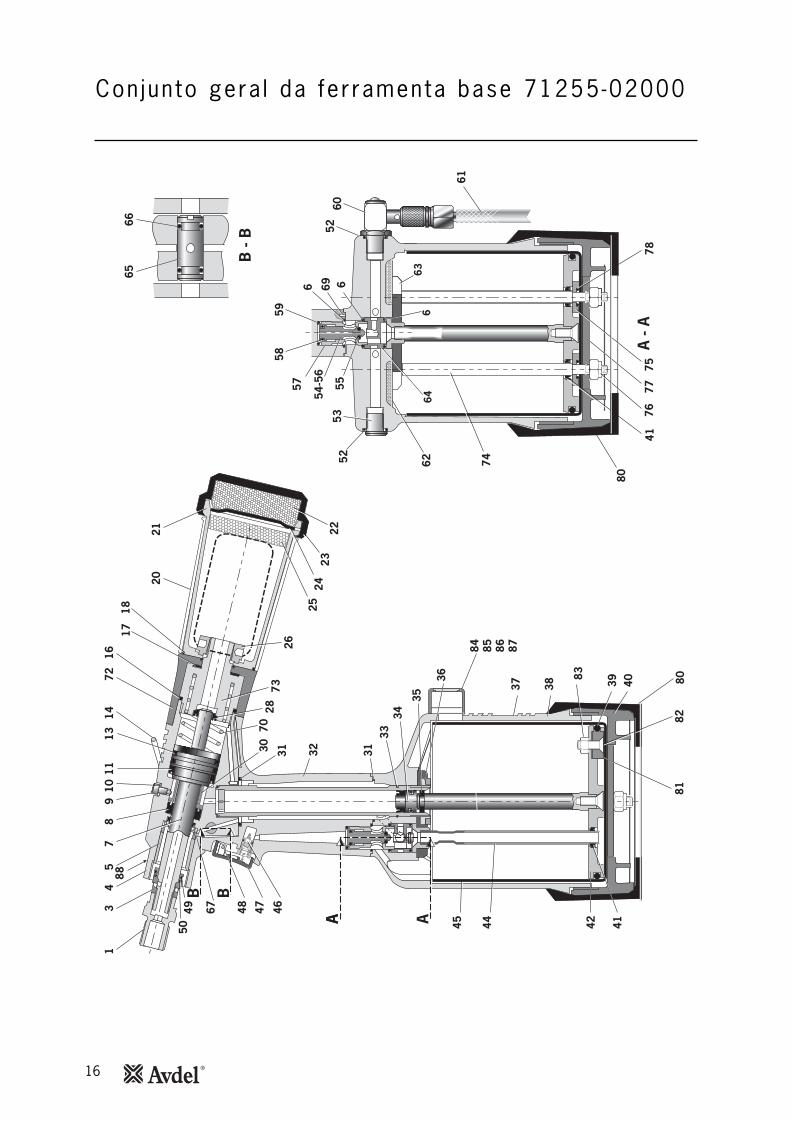
Con jun to gera l da fer ramenta base 71255-02000
B -
B
6665
37
84 85 86 87
38 4039
83
3133
34
AA 444536
35
BB
13
49
105
8
3130 32
464867 47
5049
2673
7028
7216
1718
14
2021 22
2524
117
A23
1388
42 41
8082
81
A -
A
664
5958
57
54-5
6
5552
536
61
6052
696
74
80
4176
7577
78
6263
17
01 03 04 05 06 07 08 09 10 11 13 14 16 17 18 20 21 22 23 24 25 26 28 30 31 32 33 34 35 36 37 38 39 40 41 42 44 45 46 47
0761
0-00
501
7123
0-02
015
7123
0-03
300
7121
0-02
104
0700
3-00
281
7123
1-02
003
0700
3-00
273
7123
0-02
041
0700
3-00
194
0700
3-00
341
0700
3-00
342
7121
0-02
022
0700
3-00
278
7121
0-02
029
0700
3-00
311
0764
0-00
239
7121
0-02
051
0764
0-00
244
7121
0-02
034
0734
0-00
335
7121
0-02
035
7121
0-02
028
0700
3-00
374
7123
0-02
019
0700
3-00
288
7122
1-02
013
0700
3-00
287
7123
0-03
800
7123
0-03
205
7121
0-02
014
7125
5-02
027
7121
1-02
001
0700
3-00
280
7121
1-02
002
0700
3-00
274
7125
5-03
200
7121
0-03
600
7121
1-02
008
0700
5-00
088
7121
0-02
008
ADAP
TADO
R DE
BUC
HACO
NTR
APO
RCA
CON
JUN
TO D
A CA
BEÇA
INVÓ
LUCR
O D
E VE
DAN
TE
‘O’ R
ING
PIST
ÃO D
A CA
BEÇA
JUN
TA D
E LÁ
BIO
PARA
FUSO
VEDA
NTE
JUN
TA D
E LÁ
BIO
'O' R
ING
ANEL
DE
SUSP
ENSÃ
O'O
' RIN
GVE
DAN
TE‘O
’RIN
GEX
TERI
OR
DO C
APTA
DOR
DE H
ASTE
S #
CORP
O D
O C
APTA
DOR
DE H
ASTE
S #
SILE
NCI
ADO
R #
TAM
PA D
O S
ILEN
CIAD
OR
#TA
MPA
DA
EXTR
EMID
ADE
DO C
APTA
DOR
DE H
ASTE
S #
SILE
NCI
ADO
R #
PORC
A DE
RET
ENÇÃ
OJU
NTA
DE
LÁBI
ORE
TEN
TOR
DE V
EDAN
TE'O
' RIN
GCO
NJU
NTO
DO
PUN
HO'O
' RIN
GCO
NJU
NTO
VED
ANTE
ANEL
GUI
APO
RCA
DE A
PERT
OET
IQUE
TACO
RPO
'O' R
ING
TAM
PA D
A BA
SEJU
NTA
DE
LÁBI
OCO
NJU
NTO
DO
PIS
TÃO
PN
EUM
ÁTIC
O (I
NCL
UI 4
1/35
/39)
CON
JUN
TO D
O T
UBO
DE
TRAN
SFER
ÊNCI
ARE
VEST
IMEN
TO D
E CI
LIN
DRO
VÁLV
ULA
DO G
ATIL
HOG
ATIL
HO
1 1 1 1 3 1 1 1 1 1 2 1 1 1 1 1 1 1 1 1 1 1 1 1 1 2 1 1 1 1 1 1 1 1 3 1 1 1 1 1
- 1 - - 3 - 1 1 2 1 2 1 1 1 1 - - 1 - - 1 - - - - 2 1 1 - - 1 - 1 - 1 - - - - -
48 49 50 52 53 54 55 56 57 58 59 60 61 62 63 64 65 66 67 69 70 72 73 74 75 76 77 78 79 80 81 82 83 84 85 86 87 88
7121
0-02
024
0700
3-00
310
0700
3-00
204
0700
3-00
127
0700
5-01
274
7121
0-03
400
0700
3-00
268
7121
0-03
402
7121
0-03
401
0700
3-00
042
0700
3-00
271
7121
0-03
700
0700
8-00
010
7121
0-02
031
7122
1-02
003
7121
0-02
009
7121
0-02
013
0700
3-00
189
0700
3-00
333
0700
7-00
224
0749
0-03
002
7140
3-02
110
7123
1-02
001
7121
1-02
004
7122
1-02
006
0700
2-00
108
7122
1-02
005
0700
3-00
027
7122
1-02
003
7121
0-02
055
0700
7-01
993
7122
1-20
104
0700
2-00
098
7122
1-20
105
7122
1-20
101
7122
1-20
102
7122
1-20
103
0700
7-01
503
PIN
O D
O G
ATIL
HO'O
' RIN
G'O
' RIN
G‘O
’ RIN
GBU
JÃO
CON
JUN
TO D
O C
URSO
R DA
VÁL
VULA
(55
a 58
)•
'O' R
ING
• CU
RSO
R DE
VÁL
VULA
• CO
RPO
DE
VÁLV
ULA
• 'O
' RIN
G'O
' RIN
GCO
NJU
NTO
DA
VÁLV
ULA
ON
/OFF
TUBO
FLE
XÍVE
LSI
LEN
CIAD
OR
CHAP
A DE
APE
RTO
SEDE
DE
VÁLV
ULA
VÁLV
ULA
ROTA
TIVA
'O' R
ING
JUN
TA D
E LÁ
BIO
PIN
O D
E M
OLA
MO
LACO
NJU
NTO
DO
ADA
PTAD
OR
DE "G
ARRA
FA"
CON
JUN
TO D
A TA
MPA
DA
EXTR
EMID
ADE
TIRA
NTE
ANIL
HA D
E VE
DAÇÃ
OPO
RCA
NYL
OK
M6
PLAC
A DA
BAS
E'O
' RIN
GPL
ACA
SUPE
RIO
RRE
SGUA
RDO
DE
BORR
ACHA
ÍMAN
DE
PÓLO
CEN
TRAL
PARA
FUSO
DE
CABE
ÇA D
E EM
BEBE
R M
5 X
19PO
RCA
NYL
OK
M5
CON
TADO
RM
OLD
E DE
CO
NTA
DOR
PARA
FUSO
ESP
ECIA
L M
4PO
RCA
DE R
ETEN
ÇÃO
DO
MO
LDE
ETIQ
UETA
CO
M S
ÍMBO
LO D
E LI
VRO
1 2 1 1 1 1 1 1 1 1 1 1 1 2 1 1 1 2 1 2 1 1 1 2 2 2 1 2 1 1 1 1 1 1 1 2 2 1
- 2 1 - - - 2 - - 2 1 - - 2 - 1 – 2 - 1 - - - - - - - - - - - - - - - - - - -
#
Est
es i
tens
tam
bém
est
ão d
isp
onív
eis
com
o um
kit
com
ple
to r
efer
ênci
a 7
12
10
-20
40
0.
71
25
5-0
20
00
LIS
TA
DE
PE
ÇA
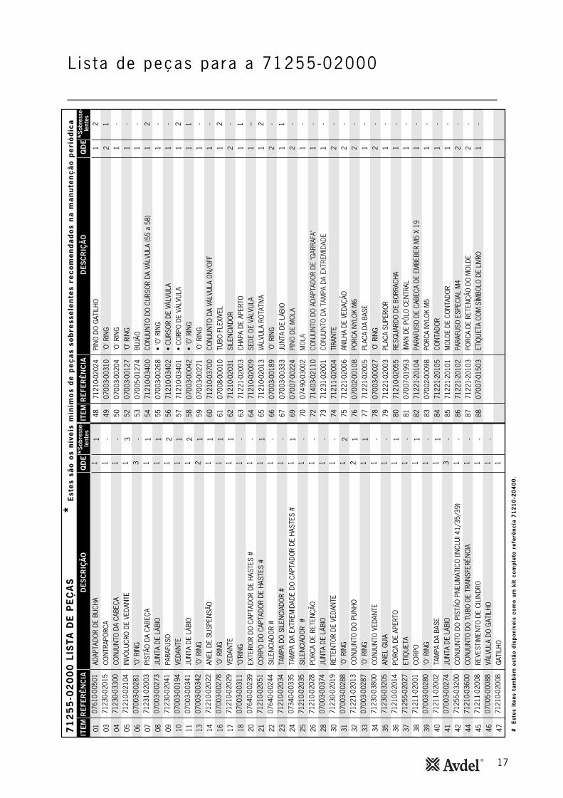
S*
Est
es
são
os
nív
eis
mín
imo
s d
e p
eç
as
sob
ress
ele
nte
s re
co
me
nd
ad
os
na
ma
nu
ten
çã
o p
eri
ód
ica
ITE
MR
EFE
RÊ
NC
IAD
ES
CR
IÇÃ
OQ
DE
*Sob
ress
e-le
ntes
ITEM
RE
FER
ÊN
CIA
DE
SC
RIÇ
ÃO
QD
E*S
obre
sse-
lent
es
L is ta de peças para a 71255-02000
18
Preparação
Pormenores do ó leo
Dados de segurança para o ó leo Hysp in® VG 32
Ki t de preparação
Para poder seguir o procedimento de preparação ao lado, precisa de obter um kit de preparação:
07900-00351 07900-00698 07900-0070007900-0022407900-00734
CHAVE TIPO ALLEN DE 3 mmPORCA DE ESBARROBOMBA DE PREPARAÇÃOCHAVE ALLEN DE 4 mmPORCA DE ESBARRO MAXLOK®
REFERÊNCIA DESCRIÇÃO
KIT DE PREPARAÇÃO : 07900-00688
A preparação é SEMPRE necessária depois de se ter desmontado a ferramenta e antes de a operar. Poderá também ser necessáriorestaurar o curso completo após uso considerável, quando o curso tiver reduzido e os elementos de fixação não foremcompletamente colocados por uma operação de gatilho.
O óleo recomendado para a preparação é Hyspin® VG32 disponível em recipientes de 0,5l (ref. 07992-00002) ou de 1 galão (ref. 07992-00006). Consulte os dados de segurança abaixo.
Primeiros socorrosPELE:Lave muito bem com água e sabão o mais depressa possível. Contacto ocasional não requer atenção imediata. Contacto temporário nãorequer atenção imediata. INGESTÃO:Consulte imediatamente o médico. NÃO provoque vómitos.OLHOS:Irrigue imediatamente com água durante vários minutos. Embora NÃO seja um irritante primário, após contacto poderá ocorrer um ligeira irritação.
IncendioPONTO DE INFLAMAÇÃO: 232°C. Não é classificado como inflamável.Meios de extinção adequados: CO2, pó seco, espuma ou neblina de água. NÃO utilize jactos de água.
AmbientalDESCARTE: Através de um contratante autorizado para um local aprovado. Pode ser incinerado. Produto utilizado pode ser enviado para recuperação.DERRAMAMENTO: Evite a entrada para esgotos, fossas e cursos de água. Limpe com material absorvente.
ManuseamentoUse protecção de olhos, luvas impermeáveis (p.ex. de PVC) e um avental de plástico. Utilize em áreas bem ventiladas.
ArmazenamentoNão são necessárias precauções especiais.
19
I M P O R T A N T E
DESLIGUE A FERRAMENTA DO ABASTECIMENTO DE AR OU DESLIGUE NA VÁLVULA 63.REMOVA O CONJUNTO DE PONTA OU OS COMPONENTES DA CABEÇA ROTATIVA.
Todas as operações deverão ser realizadas numa bancada limpa, com mãos limpas numa área limpa.Certifique-se de que o novo óleo está completamente limpo e sem bolhas de ar.
Dever-se-á ter SEMPRE cuidado para assegurar que substâncias estranhas não entrem na ferramenta ou poderáresultar em sérios danos.
• Retire o parafuso de sangria 9 e o vedante unido 10.
• Ligue o abastecimento de ar da ferramenta e coloque a válvula ON/OFF 60 na posição ‘ON’.
• Inverta a ferramenta sobre um recipiente adequado e accione o gatilho. O óleo de refugo será expulsado através do orifício doparafuso de sangria.
DEVER-SE-Á ASSEGURAR QUE O ORIFÍCIO DE SANGRIA NÃO ESTÁ VIRADO PARA O OPERADOR OU OUTRAS PESSOAS.
• Aparafuse a porca de esbarro 07900-00734 no adaptador de bucha 1.
• Desligue o abastecimento de ar da ferramenta e ponha a válvula ON/OFF 60 na posição OFF.
• Encha a bomba de preparação com óleo.
• Aparafuse a bomba de ferrar 07900-00700 no furo do parafuso de sangria com o vedante unido 10 em posição.
• Accione a bomba de preparação pressionando e soltando várias vezes até sentir resistência.
• Remova a bomba de preparação e a porca de esbarro.
• Volte a colocar o parafuso de sangria 9 e o vedante 10.
• Ligue o abastecimento de ar à ferramenta e coloque o interruptor de ligar/desligar do conjunto da válvula na posição 'ON'(ligada).
• Verifique que o curso da ferramenta está de acordo com a especificação mínima de 13 milímetros. Para verificar o curso, meçaa distância entre a face frontal do adaptador de bucha 1 e a face frontal da cabeça, ANTES de premir o gatilho e quando ogatilho estiver completamente accionado. O curso é a diferença entre estas duas medições. Se a especificação mínima não forsatisfeita, repita o procedimento de ferragem.
As referências das peças em negrito referem-se ao conjunto geral e à lista de peças nas páginas 16-17.
P reparaçãoProcedimento de preparação
20
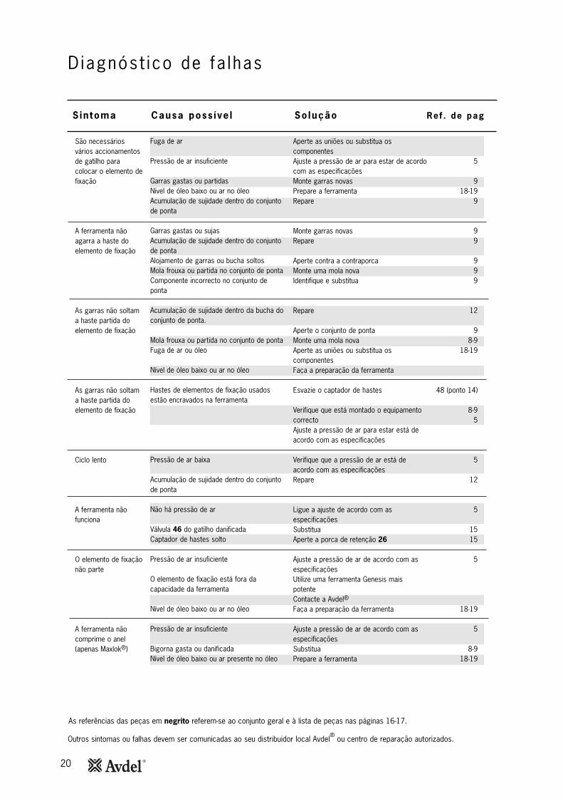
D iagnóst ico de fa lhas
Sintoma Causa poss íve l So lução Ref . de pag
As referências das peças em negrito referem-se ao conjunto geral e à lista de peças nas páginas 16-17.
Outros sintomas ou falhas devem ser comunicadas ao seu distribuidor local Avdel® ou centro de reparação autorizados.
São necessáriosvários accionamentosde gatilho paracolocar o elemento defixação
A ferramenta nãoagarra a haste doelemento de fixação
As garras não soltama haste partida doelemento de fixação
As garras não soltama haste partida doelemento de fixação
Ciclo lento
A ferramenta nãofunciona
O elemento de fixaçãonão parte
A ferramenta nãocomprime o anel(apenas Maxlok®)
Fuga de ar
Pressão de ar insuficiente
Garras gastas ou partidasNível de óleo baixo ou ar no óleoAcumulação de sujidade dentro do conjuntode ponta
Garras gastas ou sujasAcumulação de sujidade dentro do conjuntode pontaAlojamento de garras ou bucha soltosMola frouxa ou partida no conjunto de pontaComponente incorrecto no conjunto deponta
Acumulação de sujidade dentro da bucha doconjunto de ponta.
Mola frouxa ou partida no conjunto de pontaFuga de ar ou óleo
Nível de óleo baixo ou ar no óleo
Hastes de elementos de fixação usadosestão encravados na ferramenta
Pressão de ar baixa
Acumulação de sujidade dentro do conjuntode ponta
Não há pressão de ar
Válvula 46 do gatilho danificadaCaptador de hastes solto
Pressão de ar insuficiente
O elemento de fixação está fora dacapacidade da ferramenta
Nível de óleo baixo ou ar no óleo
Pressão de ar insuficiente
Bigorna gasta ou danificada Nível de óleo baixo ou ar presente no óleo
Aperte as uniões ou substitua oscomponentesAjuste a pressão de ar para estar de acordocom as especificaçõesMonte garras novasPrepare a ferramentaRepare
Monte garras novasRepare
Aperte contra a contraporcaMonte uma mola novaIdentifique e substitua
Repare
Aperte o conjunto de pontaMonte uma mola novaAperte as uniões ou substitua oscomponentesFaça a preparação da ferramenta
Esvazie o captador de hastes
Verifique que está montado o equipamentocorrectoAjuste a pressão de ar para estar está deacordo com as especificações
Verifique que a pressão de ar está deacordo com as especificaçõesRepare
Ligue a ajuste de acordo com asespecificaçõesSubstituaAperte a porca de retenção 26
Ajuste a pressão de ar de acordo com asespecificaçõesUtilize uma ferramenta Genesis maispotenteContacte a Avdel®
Faça a preparação da ferramenta
Ajuste a pressão de ar de acordo com asespecificaçõesSubstituaPrepare a ferramenta
5
918-19
9
99
999
12
98-9
18-19
48 (ponto 14)
8-95
5
12
5
1515
5
18-19
5
8-918-19

21
Notas

22
Notas
23
Data de Emissão
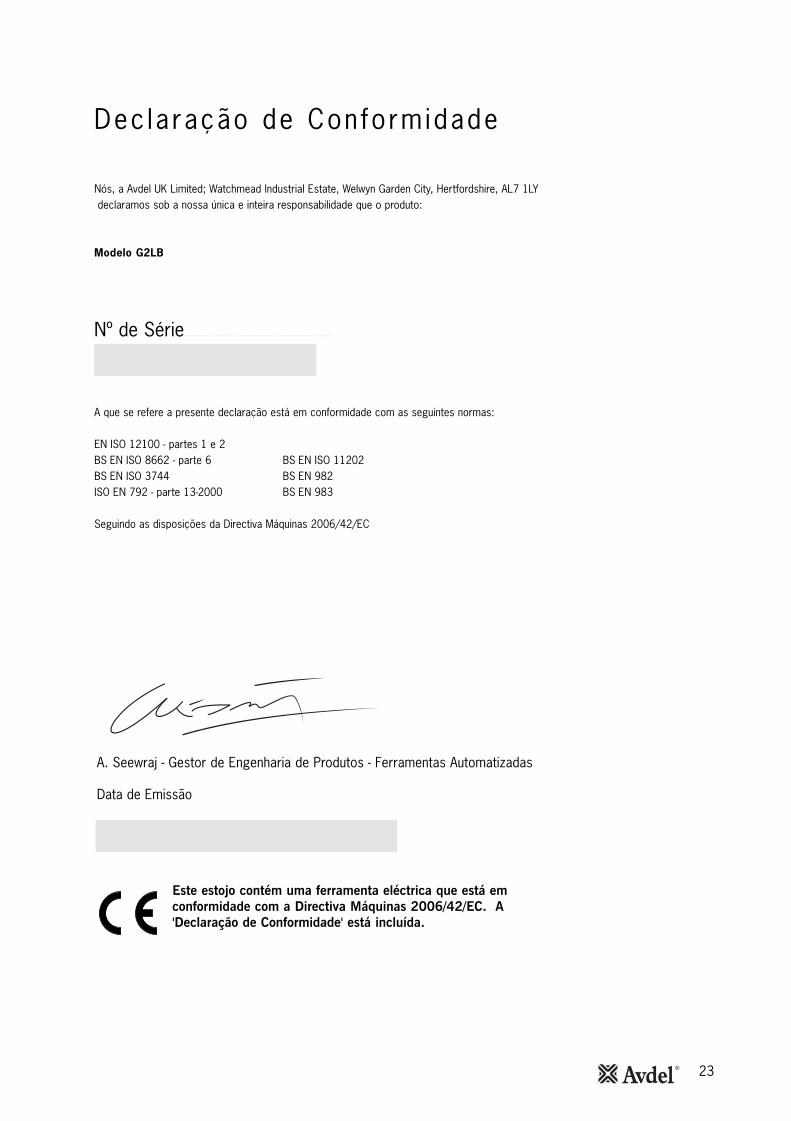
A. Seewraj - Gestor de Engenharia de Produtos - Ferramentas Automatizadas
Este estojo contém uma ferramenta eléctrica que está emconformidade com a Directiva Máquinas 2006/42/EC. A'Declaração de Conformidade' está incluída.
Dec laração de Conformidade
Nós, a Avdel UK Limited; Watchmead Industrial Estate, Welwyn Garden City, Hertfordshire, AL7 1LYdeclaramos sob a nossa única e inteira responsabilidade que o produto:
Modelo G2LB
Nº de Série................................................
A que se refere a presente declaração está em conformidade com as seguintes normas:
EN ISO 12100 - partes 1 e 2BS EN ISO 8662 - parte 6 BS EN ISO 11202BS EN ISO 3744 BS EN 982ISO EN 792 - parte 13-2000 BS EN 983
Seguindo as disposições da Directiva Máquinas 2006/42/EC
Since 1 936 2010 Since 1922
www.avdel-global.comwww.infastech.com
02.2
011
• ©
201
0 In
fast
ech
Autosert® (equipment), Avbolt ®, Avdel®, Avdelmate®, Avdel TX2000®, Avdelok®, Avex®, Avibulb®, Avinox®, Avinut™, Avlug®, Avmatic®, Avplas®,Avseal®, Avsert®, Avtainer®, Avtronic®, Briv®, Bulbex®, Chobert®, Eurosert®, Fastriv®, Finsert®, Genesis®, Grovit®, Hemlok®, Hexsert®, Holding your world together®, Hydra®, Interlock®, Klamp-Tite®, Klamptite KTR®, Kvex®, Maxlok®, Monobolt®, Monobulb ®, Neobolt®, Nutsert®, Nutsert SQ®, Portariv®, Rivmatic®, Rivscrew®, Speed Fastening®, Squaresert®, Stavex®, Supersert®, Thin Sheet Nutsert®, Titan®, T-Lok®, TLR®, TSN®, TX2000®, Versa-Nut®, Viking® e Viking 360 ® são marcas comerciais da Avdel UK Limited. Infastech™ e Our Technology, Your Success™ são marcas comerciais da Infastech Intellectual Properties Pte Ltd. Os nomes e logótipos de outras empresas mencionadas neste documento podem ser marcas comerciais dos seus respectivos proprietários. Este documento tem objectivos meramente informativos. A Infastech não oferece quaisquer garantias, explícitas ou implícitas, neste documento. Os dados apresentados estão sujeitos a alterações sem aviso prévio em virtude do desenvolvimento contínuo do produto e do melhoramento da política. O seu representante local Avdel está à sua disposição caso precise de confirmar esta última informação.
AUSTRÁLIAInfastech (Australia) Pty Ltd.891 Wellington RoadRowvilleVictoria 3178Tel: +61 3 9765 6400Fax: +61 3 9765 [email protected]
CANADÁAvdel Canada Limited1030 Lorimar DriveMississaugaOntario L5S 1R8Tel: +1 905 364 0664Fax: +1 905 364 [email protected]
CHINAInfastech (China) Ltd.RM 1708, 17/F., Nanyang Plaza,57 Hung To Rd., Kwun TongHong KongTel: +852 2950 0631Fax: +852 2950 [email protected]
FRANÇAAvdel France S.A.S.33 bis, rue des ArdennesBP4 75921 Paris Cedex 19Tel: +33 (0) 1 4040 8000Fax: +33 (0) 1 4208 [email protected]
ALEMANHAAvdel Deutschland GmbHKlusriede 2430851 LangenhagenTel: +49 (0) 511 7288 0Fax: +49 (0) 511 7288 [email protected]
ÍNDIAInfastech Fastening Technologies India Private LimitedPlot No OZ-14, Hi Tech SEZ,SIPCOT Industrial Growth Center,Oragadam, Sriperumbudur Taluk, Kanchipuram District,602105 TamilnaduTel: +91 44 4711 8001Fax: +91 44 4711 [email protected]
ITÁLIAAvdel Italia S.r.l.Viale Lombardia 51/5320047 Brugherio (MI)Tel: +39 039 289911Fax: +39 039 [email protected]
JAPÃOInfastech Kabushiki KaishaCenter Minami SKY, 3-1 Chigasaki-Chuo, Tsuzuki-ku,Yokohama-city, Kanagawa PrefectureJapan 224-0032Tel: +81 45 947 1200Fax: +81 45 947 [email protected]
MALÁSIAInfastech (Malaysia) Sdn BhdLot 63, Persiaran Bunga Tanjung 1,Senawang Industrial Park70400 SerembanNegeri SembilanTel: +606 676 7168Fax: +606 676 [email protected]
SINGAPURAInfastech (Singapore) Pte Ltd. 31 Kaki Bukit Road 3#05-03/06 TechlinkSingapore, 417818Tel: +65 6372 5653Fax: +65 6744 [email protected]
REPÚBLICA DA COREIAInfastech (Korea) Ltd.212-4, Suyang-Ri,Silchon-Eup, Kwangju-City,Kyunggi-Do, Korea, 464-874Tel: +82 31 798 6340Fax: +82 31 798 [email protected]
ESPANHAAvdel Spain S.A.C/ Puerto de la Morcuera, 14Poligono Industrial Prado OveraCtra. de Toledo, km 7,828919 Leganés (Madrid)Tel: +34 91 3416767Fax: +34 91 [email protected]
TAIWANInfastech/Tri-Star LimitedNo 269-7, Baodong Rd, Guanmiao Township,71841 Tainan County,Taiwan, R.O.CTel: +886 6 596 5798 (ext 201)Fax: +886 6 596 [email protected]
REINO UNIDOAvdel UK LimitedPacific House2 SwiftfieldsWatchmead Industrial EstateWelwyn Garden CityHertfordshire AL7 1LYTel: +44 (0) 1707 292000Fax: +44 (0) 1707 [email protected]
EUAAvdel USA LLC614 NC Highway 200 SouthStanfield, North Carolina 28163Tel: +1 704 888 7100Fax: +1 704 888 [email protected]
Manual No. Issue Change Note No.
AC 03/274
B 07/044
B2 07/103
B3 08/096
B4 11/061
07900-00834
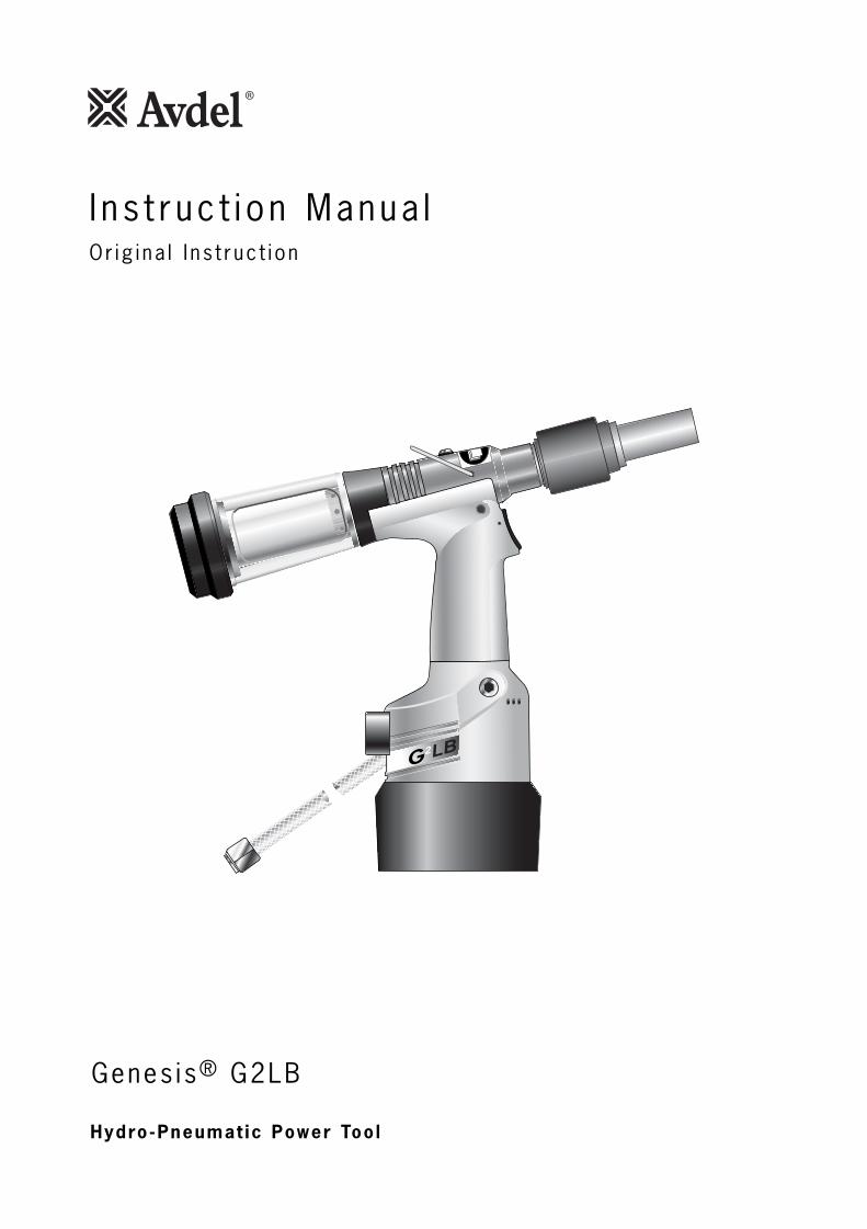
Genes is® G2LB
2
Hydro-Pneumat ic Power Too l
I n s t ruc t i on Manua lOr ig i na l I ns t ruc t i on

3
Safety Rules 4
SpecificationsTool Specification 5Tool Dimensions 5
Intent of UsePart Numbering 6
Putting into ServiceAir Supply 7Operating Procedure 7
Nose AssembliesAvdelok® and Maxlok® Nose Assemblies 8Fitting Instructions Avdelok® 9Servicing Instructions 9Fitting Instructions Maxlok® 10Servicing Instructions 10
AccessoriesStem Deflector 11Extension 11
Servicing the ToolDaily 12Weekly 12Moly Lithium Grease EP 3753 Safety Data 12MolyKote® 55m Safety Data 13MolyKote® 111 Safety Data 13Annually 14Service Kit 14Head Assembly 14-15Pneumatic Piston Assembly 15Valve Spool Assembly 15Trigger 15
General Assembly of Base ToolGeneral Assembly and Parts List 16-17
Contents
LIMITED WARRANTYAvdel makes the limited warranty that its products will be free of defects in workmanship and materialswhich occur under normal operating conditions. This Limited Warranty is contingent upon: (1) the productbeing installed, maintained and operated in accordance with product literature and instructions, and (2)confirmation by Avdel of such defect, upon inspection and testing. Avdel makes the foregoing limitedwarranty for a period of twelve (12) months following Avdel’s delivery of the product to the direct purchaserfrom Avdel. In the event of any breach of the foregoing warranty, the sole remedy shall be to return thedefective Goods for replacement or refund for the purchase price at Avdel’s option. THE FOREGOINGEXPRESS LIMITED WARRANTY AND REMEDY ARE EXCLUSIVE AND ARE IN LIEU OF ALL OTHER WARRANTIESAND REMEDIES. ANY IMPLIED WARRANTY AS TO QUALITY, FITNESS FOR PURPOSE, OR MERCHANTABILITYARE HEREBY SPECIFICALLY DISCLAIMED AND EXCLUDED BY AVDEL.
Avdel UK Limited policy is one of continuous product development and improvement and we reserve the right to change the specification of any product without prior notice.
PrimingOil Details 18Hyspin® VG 32 Safety Data 18Priming Kit 18Priming Procedure 19
Fault DiagnosisSymptom, Possible Cause and Remedy 20
4
Sa fe ty Ru les
1 Do not use outside the design intent.
2 Do not use equipment with this tool/machine other than that recommended and supplied by Avdel UK Limited.
3 Any modification undertaken by the customer to the tool/machine, nose assemblies, accessories or any equipment supplied by
Avdel UK Limited or their representatives, shall be the customer’s entire responsibility. Avdel UK Limited will be pleased to advise
upon any proposed modification.
4 The tool/machine must be maintained in a safe working condition at all times and examined at regular intervals for damage and
function by trained competent personnel. Any dismantling procedure shall be undertaken only by personnel trained in Avdel UK
Limited procedures. Do not dismantle this tool/machine without prior reference to the maintenance instructions. Please contact
Avdel UK Limited with your training requirements.
5 The tool/machine shall at all times be operated in accordance with relevant Health and Safety legislation. In the U.K. the “Health
and Safety at Work etc. Act 1974” applies. Any question regarding the correct operation of the tool/machine and operator
safety should be directed to Avdel UK Limited.
6 The precautions to be observed when using this tool/machine must be explained by the customer to all operators.
7 Always disconnect the airline from the tool/machine inlet before attempting to adjust, fit or remove a nose assembly.
8 Do not operate a tool/machine that is directed towards any person(s) or the operator.
9 Always adopt a firm footing or a stable position before operating the tool/machine.
10 Ensure that vent holes do not become blocked or covered.
11 The operating pressure shall not exceed 7 bar.
12 Do not operate the tool if it is not fitted with a complete nose assembly unless specifically instructed otherwise.
13 Care shall be taken to ensure that spent stems are not allowed to create a hazard.
14 If the tool is fitted with a stem collector, it must be emptied when half full.
15 If the tool is fitted with a stem deflector, it should be rotated until the aperture is facing way from the operator and other
person(s) working in the vicinity.
16 When using the tool, the wearing of safety glasses is required both by the operator and others in the vicinity to protect against
fastener ejection, should a fastener be placed ‘in air’. We recommend wearing gloves if there are sharp edges or corners on the
application.
17 Take care to avoid entanglement of loose clothes, ties, long hair, cleaning rags etc. in the moving parts of the tool which should
be kept dry and clean for best possible grip.
18 When carrying the tool from place to place keep hands away from the trigger/lever to avoid inadvertent start up.
19 Excessive contact with hydraulic fluid oil should be avoided. To minimize the possibility of rashes, care should be taken to wash
thoroughly.
20 C.O.S.H.H. data for all hydraulic oils and lubricants is available on request from your tool supplier.
This instruction manual must be read with particular attention to the following safety rules, by any personinstalling, operating, or servicing this tool.

5
Dimensions in millimetres.
2
23
121
110
120
150
305
145
116
70
2
12°30'
Air Pressure Minimum - Maximum 5-7 bar (72.5 - 101.5 psi)
Free Air Volume Required @ 5.5 bar 2.1 litres
Stroke Minimum 13mm
Pull Force @ 5.5 bar 12.47 KN
Cycle time Approximately 1 second
Noise Level 75 dB(A)
Weight Without nose equipment 1.35 kg
Vibration Less than 2.5 m/s2 (8.2 ft/s2)
Spec i f i ca t ions
Tool Spec i f icat ion
Too l D imens ions

6
G2LB is a hydro-pneumatic tool designed to place Avdel Avdelok®/Maxlok® fasteners at high speed making it ideal for batch or flow-lineassembly in a wide variety of applications throughout all industries.
A complete tool is made up of two separate elements. See diagram below.
NOSE EQUIPMENT MUST BE FITTED AS DESCRIBED ON PAGES 8, 9 and 10.
BASE TOOL
AVDELOK® NOSE ASSEMBLY
71255-02000
71230-05010(3/16)71230-05020(1/4)
1
1
2
COMPLETE TOOL+ =1 2
2
MAXLOK® NOSE ASSEMBLY 07610-02000(3/16)07610-02100(1/4)
2
AVDELOK®
71255-00391(3/16)71255-00392(1/4)
MAXLOK®
71255-00371(3/16)71255-00372(1/4)
The part number of the base tool remains the same whichever nose assembly is fitted. See the General Assembly andParts List pages 16-17.
The nose assembly will allow placing of fasteners by simply selecting the appropriate noseassembly. See page 8.
I n ten t o f Use
Par t Number ing
7
All tools are operated with compressed air at an optimum pressure of 5.5 bar. We recommend the use of pressure regulators andautomatic filtering systems on the main air supply. These should be fitted within 3 metres of the tool (see diagram below) to ensuremaximum tool life and minimum tool maintenance.
Air supply hoses should have a minimum working effective pressure rating of 150% of the maximum pressure produced in the system or10 bar, whichever is the highest. Air hoses should be oil resistant, have an abrasion resistant exterior and should be armoured whereoperating conditions may result in hoses being damaged. All air hoses MUST have a minimum bore diameter of 6.4 millimetres or 1/4 inch.
Read daily servicing details page 12.
86
42
0
10121416
TAKE OFF POINTFROMMAIN SUPPLY
STOP COCK(USED DURING MAINTENANCE
OF FILTER/REGULATOR)
MAIN SUPPLYDRAIN POINT
PRESSURE REGULATORAND FILTER (DRAIN DAILY)
3 METRES MAXIMUM
• Ensure that the correct nose assembly is fitted.• Connect the tool to the air supply.• Disable the vacuum extraction system by turning Rotary Valve
65 until you feel or hear no air flow out of the front of thenose assembly.
• Push the fastener stem through the application hole.• Place the collar on the stem (orientation as shown).• Keeping the head of the stem against the application, push
the tool onto the protruding stem.• Fully depress the trigger. One cycle will ensure that the collar
is swaged into the lock grooves of the stem and that thestem breaks at the breaker groove.
• The tool completes its cycle by pushing itself off the collarand the spent stem will be pushed to the rear of the tool oninsertion of the next fastener.
Item numbers in bold refer to the General Assembly drawing and Parts List on pages 16-17.
Placing AVDELOK®/MAXLOK®
Put t ing in to Serv iceAir Supp ly
Operat ing Procedure
8
AV D E L O K ®
N O S E A S S E M B LY1 In inches then in millimetres
NOSE ASSEMBLY part nº71230-05010 for 4.8 (3/16 ") Avdelok®
NOSE ASSEMBLY part nº 71230-05020 for 6.4 (1/4 ") Avdelok®
ITEM DESCRIPTION PART Nº1 ANVIL CASING 71230-050122 BUFFER 71230-050143 ANVIL 71230-050114 SHROUD 71230-050135 CHUCK COLLET 07200-021016 CHUCK JAWS 07220-021027 SPRING GUIDE 07220-021048 SPRING 07220-021039 FRICTION RING 07610-0200410 nG4 CHUCK COLLET ADAPTOR
(nG4) (nG4)
07610-0050111 nG4 LOCKNUT 71233-20200
ITEM DESCRIPTION PART Nº1 ANVIL CASING 71230-050122 BUFFER 71230-050143 ANVIL 71230-050214 SHROUD 71230-050135 CHUCK COLLET 07200-022016 CHUCK JAWS 07220-023027 SPRING GUIDE 07220-021048 SPRING 07220-021039 FRICTION RING 07610-0200410 nG4 CHUCK COLLET ADAPTOR 07610-0050111 nG4 LOCKNUT 71233-20200
FA S T E N E RMATERIALØ1
N O S E A S S E M B LY seebelowPART NºNAME
AnyAny
3/161/4
71230-0501071230-05020
4.86.4
AVDELOK® … 3 9 1… 3 9 2
COMPLETE TOOL PART NUMBER :precede with 71255-00
2 1
1
3
6 5
4
8
7
9
7
11 10
Avdelok® and Maxlok® Nose Assembl ies
M A X L O K ®-N O S E A S S E M B LY 1 In inches then in millimetres
READ MAXLOK® 'FITTING INSTRUCTIONS' PAGE 10.
FA S T E N E RMATERIALØ1
N O S E A S S E M B LY seebelowPART NºNAME
AnyAl Alloy
3/161/4
07610-0200007610-02100
4.86.4
MAXLOK® … 3 7 1… 3 7 2
COMPLETE TOOL PART NUMBER :precede with 71255-00
52
19
16
NOSE ASSEMBLY NOSE ASSEMBLYpart nº 07610-02000 for 3/16 " ø part nº 07610-02100 for 1/4 " ø
ITEM DESCRIPTION PART Nº
9 CHUCK COLLET 07610-02002
4 JAWS 07610-02003
10 SPRING GUIDE 07220-02104
7 SPRING 07610-021078 LOCKING RING 07610-02004
12 ANVIL 07610-020011314 nG4 CHUCK COLLET ADAPTOR
15 ANVIL ADAPTOR16 ANVIL NUT
nG4 STOP NUT ASSY 71233-2020007610-0050171230-0206307610-00307
15 ANVIL ADAPTOR16 ANVIL NUT
71230-0206307610-00307
ITEM DESCRIPTION PART Nº
9 CHUCK COLLET 07610-02102
4 JAWS 07610-02103
10 SPRING GUIDE 07220-02104
7 SPRING 07610-021078 LOCKING RING 07610-02004
12 ANVIL 07610-021011314 nG4 CHUCK COLLET ADAPTOR 07610-00501
nG4 STOP NUT ASSY 71233-20200
15 7 10 9410 13 14 (nG4) 128 (nG4)
Nose Assembl ies
9
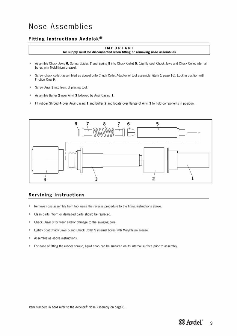
F i t t ing Ins t ruct ions Avde lok®
• Assemble Chuck Jaws 6, Spring Guides 7 and Spring 8 into Chuck Collet 5. (Lightly coat Chuck Jaws and Chuck Collet internalbores with Molylithium grease).
• Screw chuck collet (assembled as above) onto Chuck Collet Adaptor of tool assembly (item 1 page 16). Lock in position withFriction Ring 9.
• Screw Anvil 3 into front of placing tool.
• Assemble Buffer 2 over Anvil 3 followed by Anvil Casing 1.
• Fit rubber Shroud 4 over Anvil Casing 1 and Buffer 2 and locate over flange of Anvil 3 to hold components in position.
Serv ic ing Ins t ruct ions
• Remove nose assembly from tool using the reverse procedure to the fitting instructions above.
• Clean parts. Worn or damaged parts should be replaced.
• Check Anvil 3 for wear and/or damage to the swaging bore.
• Lightly coat Chuck Jaws 6 and Chuck Collet 5 internal bores with Molylithium grease.
• Assemble as above instructions.
• For ease of fitting the rubber shroud, liquid soap can be smeared on its internal surface prior to assembly.
I M P O R T A N TAir supply must be disconnected when fitting or removing nose assemblies
2 1
1
3
6 5
4
879 7
Nose Assembl ies
Item numbers in bold refer to the Avdelok® Nose Assembly on page 8.
10
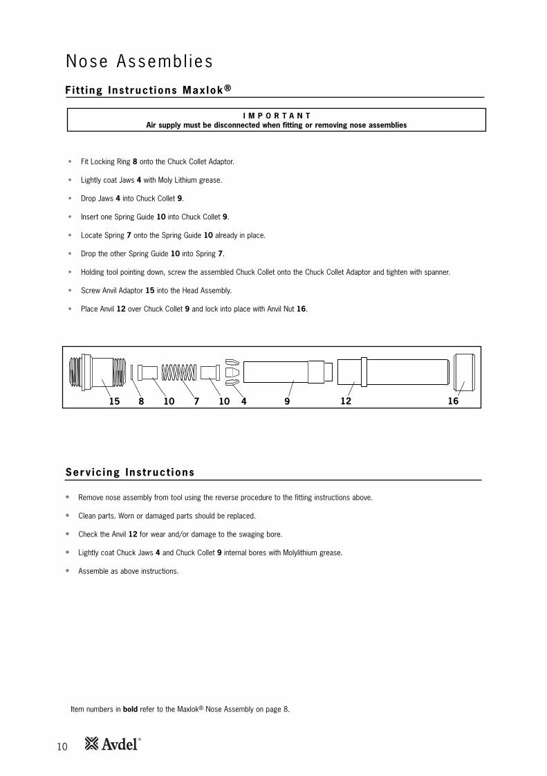
Nose Assembl ies
I M P O R T A N TAir supply must be disconnected when fitting or removing nose assemblies
• Fit Locking Ring 8 onto the Chuck Collet Adaptor.
• Lightly coat Jaws 4 with Moly Lithium grease.
• Drop Jaws 4 into Chuck Collet 9.
• Insert one Spring Guide 10 into Chuck Collet 9.
• Locate Spring 7 onto the Spring Guide 10 already in place.
• Drop the other Spring Guide 10 into Spring 7.
• Holding tool pointing down, screw the assembled Chuck Collet onto the Chuck Collet Adaptor and tighten with spanner.
• Screw Anvil Adaptor 15 into the Head Assembly.
• Place Anvil 12 over Chuck Collet 9 and lock into place with Anvil Nut 16.
F i t t ing Ins t ruct ions Maxlok®
1615 7 10 9410 128
Serv ic ing Ins t ruct ions
• Remove nose assembly from tool using the reverse procedure to the fitting instructions above.
• Clean parts. Worn or damaged parts should be replaced.
• Check the Anvil 12 for wear and/or damage to the swaging bore.
• Lightly coat Chuck Jaws 4 and Chuck Collet 9 internal bores with Molylithium grease.
• Assemble as above instructions.
Item numbers in bold refer to the Maxlok® Nose Assembly on page 8.
11
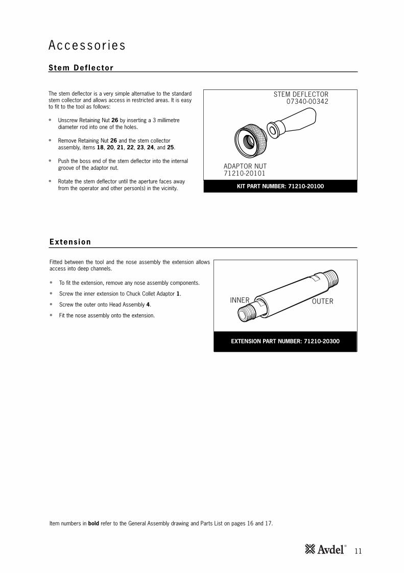
Stem Def lector
ADAPTOR NUT71210-20101
STEM DEFLECTOR07340-00342
KIT PART NUMBER: 71210-20100
The stem deflector is a very simple alternative to the standardstem collector and allows access in restricted areas. It is easyto fit to the tool as follows:
• Unscrew Retaining Nut 26 by inserting a 3 millimetrediameter rod into one of the holes.
• Remove Retaining Nut 26 and the stem collectorassembly, items 18, 20, 21, 22, 23, 24, and 25.
• Push the boss end of the stem deflector into the internalgroove of the adaptor nut.
• Rotate the stem deflector until the aperture faces awayfrom the operator and other person(s) in the vicinity.
Accessor ies
Item numbers in bold refer to the General Assembly drawing and Parts List on pages 16 and 17.
INNER OUTER
EXTENSION PART NUMBER: 71210-20300
Fitted between the tool and the nose assembly the extension allowsaccess into deep channels.
• To fit the extension, remove any nose assembly components.
• Screw the inner extension to Chuck Collet Adaptor 1.
• Screw the outer onto Head Assembly 4.
• Fit the nose assembly onto the extension.
Extens ion
12
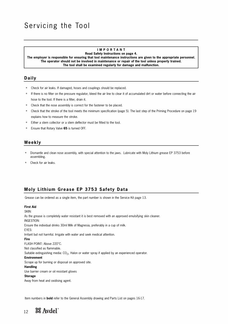
• Check for air leaks. If damaged, hoses and couplings should be replaced.
• If there is no filter on the pressure regulator, bleed the air line to clear it of accumulated dirt or water before connecting the air
hose to the tool. If there is a filter, drain it.
• Check that the nose assembly is correct for the fastener to be placed.
• Check that the stroke of the tool meets the minimum specification (page 5). The last step of the Priming Procedure on page 19
explains how to measure the stroke.
• Either a stem collector or a stem deflector must be fitted to the tool.
• Ensure that Rotary Valve 65 is turned OFF.
• Dismantle and clean nose assembly, with special attention to the jaws. Lubricate with Moly Lithium grease EP 3753 beforeassembling.
• Check for air leaks.
Grease can be ordered as a single item, the part number is shown in the Service Kit page 13.
First AidSKIN:As the grease is completely water resistant it is best removed with an approved emulsifying skin cleaner.INGESTION:Ensure the individual drinks 30ml Milk of Magnesia, preferably in a cup of milk. EYES:Irritant but not harmful. Irrigate with water and seek medical attention.FireFLASH POINT: Above 220°C.Not classified as flammable.Suitable extinguishing media: CO2, Halon or water spray if applied by an experienced operator.EnvironmentScrape up for burning or disposal on approved site.HandlingUse barrier cream or oil resistant glovesStorageAway from heat and oxidising agent.
Item numbers in bold refer to the General Assembly drawing and Parts List on pages 16-17.
I M P O R T A N TRead Safety Instructions on page 4.
The employer is responsible for ensuring that tool maintenance instructions are given to the appropriate personnel.The operator should not be involved in maintenance or repair of the tool unless properly trained.
The tool shall be examined regularly for damage and malfunction.
Serv ic ing the Too l
Dai ly
Weekly
Moly L i th ium Grease EP 3753 Safety Data
13
Serv ic ing the Too lMolykote® 55m Grease Safety Data
Molykote® 111 Grease Safety Data
First Aid
SKIN:
Flush with water. Wipe off.
INGESTION:
No first aid should be needed.
EYES:
Flush with water.
Fire
FLASH POINT: Above 101.1°C. (closed cup)
Explosive Properties: No
Suitable Extinguishing Media: Carbon Dioxide, Foam, Dry Powder or fine water spray.
Water can be used to cool fire exposed containers.
Environment
Do not allow large quantities to enter drains or surface waters.
Methods for cleaning up: Scrape up and place in suitable container fitted with a lid. The spilled product produces an extremelyslippery surface.
Harmful to aquatic organisms and may cause long-term adverse effects in the aquatic environment. However, due to the physicalform and water - insolubility of the product the bioavailability is negligible.
Handling
General ventilation is recommended. Avoid skin and eye contact.
Storage
Do not store with oxidizing agents. Keep container closed and store away from water or moisture.
First Aid
SKIN:
No first aid should be needed.
INGESTION:
No first aid should be needed.
EYES:
No first aid should be needed.
INHALATION:
No first aid should be needed.
Fire
FLASH POINT: Above 101.1°C. (closed cup)
Explosive Properties: No
Suitable Extinguishing Media: Carbon Dioxide, Foam, Dry Powder or fine water spray.
Water can be used to cool fire exposed containers.
Environment
No adverse effects are predicted.
Handling
General ventilation is recommended. Avoid eye contact.
Storage
Do not store with oxidizing agents. Keep container closed and store away from water or moisture.
14
The airline must be disconnected before any servicing or dismantling is attempted unless specifically instructed otherwise.
It is recommended that any dismantling operation be carried out in clean conditions.
Before proceeding with dismantling, empty the oil from the tool following the first three steps of the 'Priming Procedure' on page 19.
Prior to dismantling the tool it is necessary to remove the nose equipment. For instructions see the Nose Assemblies section, pages 8,9 and 10.
For a complete service of the tool, we advise that you proceed with dismantling of sub-assemblies in the order shown.
After any dismantling REMEMBER to prime the tool and to fit an appropriate nose assembly.
I M P O R T A N T
Read Safety Instructions on page 4.The employer is responsible for ensuring that tool maintenance instructions are given to the appropriate
personnel.The operator should not be involved in maintenance or repair of the tool unless properly trained.
The tool should be examined regularly for damage and malfunction.
* Item included in the Service Kit.Item numbers in bold refer to the General Assembly drawing and Parts List on pages 16-17.
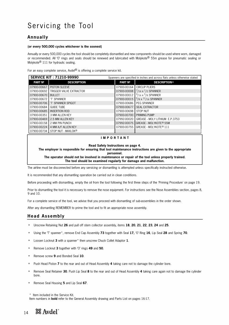
• Unscrew Retaining Nut 26 and pull off stem collector assembly, items 18, 20, 21, 22, 23, 24 and 25.
• Using the ‘T’ spanner*, remove End Cap Assembly 73 together with Seal 17, ‘O’ Ring 16, Lip Seal 28 and Spring 70.
• Loosen Locknut 3 with a spanner* then unscrew Chuck Collet Adaptor 1.
• Remove Locknut 3 together with ‘O’ rings 49 and 50.
• Remove screw 9 and Bonded Seal 10.
• Push Head Piston 7 to the rear and out of Head Assembly 4 taking care not to damage the cylinder bore.
• Remove Seal Retainer 30. Push Lip Seal 8 to the rear and out of Head Assembly 4 taking care again not to damage the cylinderbore.
• Remove Seal Housing 5 and Lip Seal 67.
PART Nº DESCRIPTIONPART Nº DESCRIPTION
SERVICE KIT : 71210-99990 Spanners are specified in inches and across flats unless otherwise stated
07900-00667 PISTON SLEEVE07900-00692 TRIGGER VALVE EXTRACTOR07900-00670 BULLET07900-00672 'T' SPANNER07900-00706 'T' SPANNER SPIGOT07900-00684 GUIDE TUBE07900-00685 INSERTION ROD07900-00351 3 MM ALLEN KEY07900-00469 2.5 MM ALLEN KEY07900-00158 2 MM PIN PUNCH07900-00224 4 MM A/F ALLEN KEY07900-00734 STOP NUT - MAXLOK
07900-00164 CIRCLIP PLIERS07900-00008 7/16 x 1/2 SPANNER07900-00012 9/16 x 5/8 SPANNER07900-00015 5/8 x 11/16 SPANNER07900-00686 PEG SPANNER07900-00677 SEAL EXTRACTOR07900-00698 STOP NUT07900-00700 PRIMING PUMP07992-00020 GREASE - MOLY LITHIUM E.P.375307992-00075 GREASE - MOLYKOTE 55M07900-00755 GREASE - MOLYKOTE 111
®
®
®
®
(or every 500,000 cycles whichever is the soonest)
Annually or every 500,000 cycles the tool should be completely dismantled and new components should be used where worn, damagedor recommended. All ‘O’ rings and seals should be renewed and lubricated with Molykote® 55m grease for pneumatic sealing orMolykote® 111 for hydraulic sealing.
For an easy complete service, Avdel® is offering a complete service kit.
Serv ic ing the Too lAnnual ly
Head Assembly
15
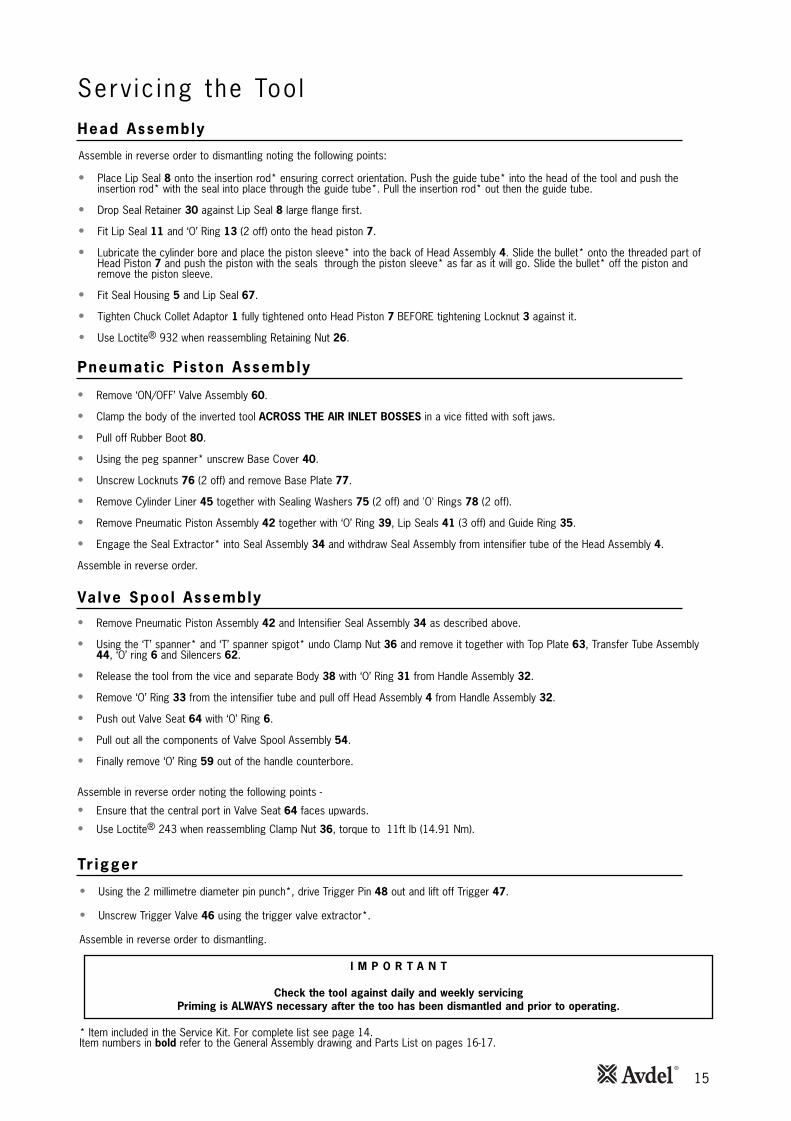
Assemble in reverse order to dismantling noting the following points:
• Place Lip Seal 8 onto the insertion rod* ensuring correct orientation. Push the guide tube* into the head of the tool and push theinsertion rod* with the seal into place through the guide tube*. Pull the insertion rod* out then the guide tube.
• Drop Seal Retainer 30 against Lip Seal 8 large flange first.
• Fit Lip Seal 11 and ‘O’ Ring 13 (2 off) onto the head piston 7.
• Lubricate the cylinder bore and place the piston sleeve* into the back of Head Assembly 4. Slide the bullet* onto the threaded part ofHead Piston 7 and push the piston with the seals through the piston sleeve* as far as it will go. Slide the bullet* off the piston andremove the piston sleeve.
• Fit Seal Housing 5 and Lip Seal 67.
• Tighten Chuck Collet Adaptor 1 fully tightened onto Head Piston 7 BEFORE tightening Locknut 3 against it.
• Use Loctite® 932 when reassembling Retaining Nut 26.
• Remove ‘ON/OFF’ Valve Assembly 60.
• Clamp the body of the inverted tool ACROSS THE AIR INLET BOSSES in a vice fitted with soft jaws.
• Pull off Rubber Boot 80.
• Using the peg spanner* unscrew Base Cover 40.
• Unscrew Locknuts 76 (2 off) and remove Base Plate 77.
• Remove Cylinder Liner 45 together with Sealing Washers 75 (2 off) and 'O' Rings 78 (2 off).
• Remove Pneumatic Piston Assembly 42 together with ‘O’ Ring 39, Lip Seals 41 (3 off) and Guide Ring 35.
• Engage the Seal Extractor* into Seal Assembly 34 and withdraw Seal Assembly from intensifier tube of the Head Assembly 4.
Assemble in reverse order.
• Remove Pneumatic Piston Assembly 42 and Intensifier Seal Assembly 34 as described above.
• Using the ‘T’ spanner* and ‘T’ spanner spigot* undo Clamp Nut 36 and remove it together with Top Plate 63, Transfer Tube Assembly44, ‘O’ ring 6 and Silencers 62.
• Release the tool from the vice and separate Body 38 with ‘O’ Ring 31 from Handle Assembly 32.
• Remove ‘O’ Ring 33 from the intensifier tube and pull off Head Assembly 4 from Handle Assembly 32.
• Push out Valve Seat 64 with ‘O’ Ring 6.
• Pull out all the components of Valve Spool Assembly 54.
• Finally remove ‘O’ Ring 59 out of the handle counterbore.
Assemble in reverse order noting the following points -
• Ensure that the central port in Valve Seat 64 faces upwards.
• Use Loctite® 243 when reassembling Clamp Nut 36, torque to 11ft lb (14.91 Nm).
• Using the 2 millimetre diameter pin punch*, drive Trigger Pin 48 out and lift off Trigger 47.
• Unscrew Trigger Valve 46 using the trigger valve extractor*.
Assemble in reverse order to dismantling.
I M P O R T A N T
Check the tool against daily and weekly servicingPriming is ALWAYS necessary after the too has been dismantled and prior to operating.
* Item included in the Service Kit. For complete list see page 14.Item numbers in bold refer to the General Assembly drawing and Parts List on pages 16-17.
Serv ic ing the Too lHead Assembly
Pneumat ic P is ton Assembly
Va lve Spoo l Assembly
Tr igger
16
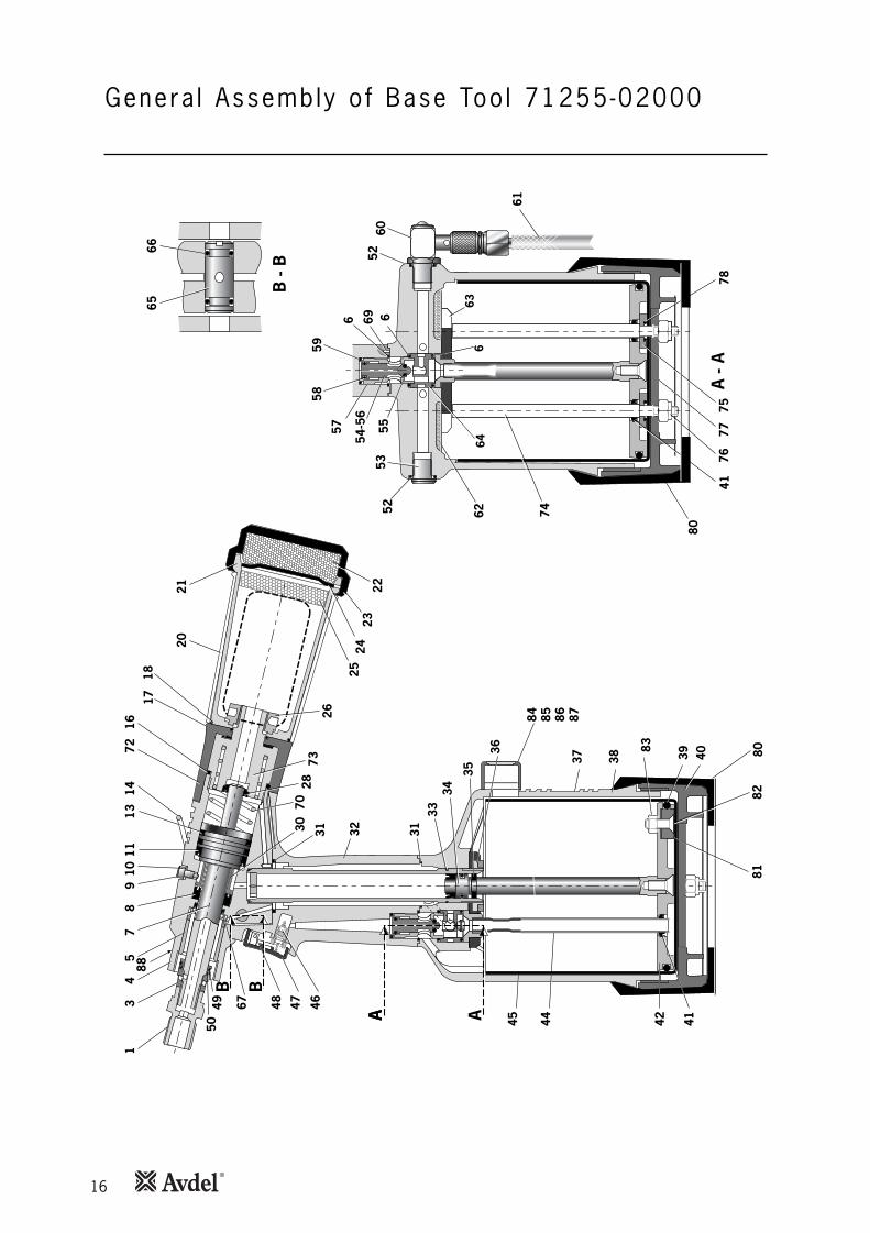
Genera l Assembly o f Base Too l 71255-02000
B -
B
6665
37
84 85 86 87
38 4039
83
3133
34
AA 444536
35
BB
13
49
105
8
3130 32
464867 47
5049
2673
7028
7216
1718
14
2021 22
2524
117
A23
1388
42 41
8082
81
A -
A
664
5958
57
54-5
6
5552
536
61
6052
696
74
80
4176
7577
78
6263

17
Par ts L is t for 71255-0200001 03 04 05 06 07 08 09 10 11 13 14 16 17 18 20 21 22 23 24 25 26 28 30 31 32 33 34 35 36 37 38 39 40 41 42 44 45 46 47
0761
0-00
501
7123
0-02
015
7123
0-03
300
7121
0-02
104
0700
3-00
281
7123
1-02
003
0700
3-00
273
7123
0-02
041
0700
3-00
194
0700
3-00
341
0700
3-00
342
7121
0-02
022
0700
3-00
278
7121
0-02
029
0700
3-00
311
0764
0-00
239
7121
0-02
051
0764
0-00
244
7121
0-02
034
0734
0-00
335
7121
0-02
035
7121
0-02
028
0700
3-00
374
7123
0-02
019
0700
3-00
288
7122
1-02
013
0700
3-00
287
7123
0-03
800
7123
0-03
205
7121
0-02
014
7125
5-02
027
7121
1-02
001
0700
3-00
280
7121
1-02
002
0700
3-00
274
7125
5-03
200
7121
0-03
600
7121
1-02
008
0700
5-00
088
7121
0-02
008
CHUC
K CO
LLET
ADA
PTO
RLO
CKN
UTHE
AD A
SSEM
BLY
SEAL
HO
USIN
G'O
' RIN
GHE
AD P
ISTO
NLI
P SE
ALSC
REW
BON
DED
SEAL
LIP
SEAL
'O' R
ING
SUSP
ENSI
ON
RIN
G'O
' RIN
GSE
AL'O
' RIN
GST
EM C
OLL
ECTO
R O
UTER
#
STEM
CO
LLEC
TOR
BODY
#SI
LEN
CER
#SI
LEN
CER
CAP
#ST
EM C
OLL
ECTO
R EN
D CA
P #
SILE
NCE
R #
RETA
ININ
G N
UT
LIP
SEAL
SEAL
RET
AIN
ER'O
' RIN
GHA
NDL
E AS
SEM
BLY
'O' R
ING
INTE
NSI
FIER
SEA
L AS
SEM
BLY
GUI
DE R
ING
CLAM
P N
UTLA
BEL
BODY
'O' R
ING
BASE
CO
VER
LIP
SEAL
PNEU
MAT
IC P
ISTO
N A
SSEM
BLY
(INCL
UDES
41/
35/3
9)TR
ANSF
ER T
UBE
ASSE
MBL
YCY
LIN
DER
LIN
ERTR
IGGE
R VA
LVE
TRIG
GER
1 1 1 1 3 1 1 1 1 1 2 1 1 1 1 1 1 1 1 1 1 1 1 1 1 2 1 1 1 1 1 1 1 1 3 1 1 1 1 1
- 1 - - 3 - 1 1 2 1 2 1 1 1 1 - - 1 - - 1 - - - - 2 1 1 - - 1 - 1 - 1 - - - - -
48 49 50 52 53 54 55 56 57 58 59 60 61 62 63 64 65 66 67 69 70 72 73 74 75 76 77 78 79 80 81 82 83 84 85 86 87 88
7121
0-02
024
0700
3-00
310
0700
3-00
204
0700
3-00
127
0700
5-01
274
7121
0-03
400
0700
3-00
268
7121
0-03
402
7121
0-03
401
0700
3-00
042
0700
3-00
271
7121
0-03
700
0700
8-00
010
7121
0-02
031
7122
1-02
003
7121
0-02
009
7121
0-02
013
0700
3-00
189
0700
3-00
333
0700
7-00
224
0749
0-03
002
7140
3-02
110
7123
1-02
001
7121
1-02
004
7122
1-02
006
0700
2-00
108
7122
1-02
005
0700
3-00
027
7122
1-02
003
7121
0-02
055
0700
7-01
993
7122
1-20
104
0700
2-00
098
7122
1-20
105
7122
1-20
101
7122
1-20
102
7122
1-20
103
0700
7-01
503
TRIG
GER
PIN
'O' R
ING
'O' R
ING
'O' R
ING
1/8"
BSP
PLU
GVA
LVE
SPO
OL
ASSE
MBL
Y (5
5 to
58)
• 'O
' RIN
G•
VALV
E SP
OO
L•
VALV
E BO
DY•
'O' R
ING
'O' R
ING
ON
/OFF
VAL
VE A
SSEM
BLY
6" F
LEXI
BLE
HOSE
SILE
NCE
RTO
P PL
ATE
VALV
E SE
ATRO
TARY
VAL
VE'O
' RIN
GLI
P SE
ALSP
IRO
L PI
NS
SPRI
NG
BOTT
LE A
DAPT
OR
ASSE
MBL
YEN
D CA
P AS
SEM
BLY
TIE
ROD
SEAL
ING
WAS
HER
M6
NYL
OK
NUT
BASE
PLA
TE'O
' RIN
GTO
P PL
ATE
RUBB
ER B
OO
TCE
NTR
E PO
LE M
AGN
ETM
5 X
19 C
OUN
TERS
UNK
SCRE
WM
5 N
YLO
K N
UTCO
UNTE
RCO
UNTE
R M
OUL
DIN
GSP
ECIA
L M
4 SC
REW
MO
ULD
RETA
ININ
G N
UTLA
BEL
BOO
K SY
MBO
L
1 2 1 1 1 1 1 1 1 1 1 1 1 2 1 1 1 2 1 2 1 1 1 2 2 2 1 2 1 1 1 1 1 1 1 2 2 1
- 2 1 - - - 2 - - 2 1 - - 2 - 1 – 2 - 1 - - - - - - - - - - - - - - - - - - -
ITEM
PAR
T N
ºD
ESC
RIP
TIO
NIT
EMPA
RT
Nº
DES
CR
IPTI
ON
71
25
5-0
20
00
PA
RT
S L
IST
* T
he
se a
re m
inim
um
re
co
mm
en
de
d l
eve
ls o
f sp
are
s b
ase
d o
n r
eg
ula
r se
rvic
ing
QTY
SPAR
ESQ
TYSP
ARES
#
Thes
e it
ems
are
also
ava
ilab
le a
s a
com
ple
te k
it.
Par
t N
umb
er 7
12
10
-20
40
0.
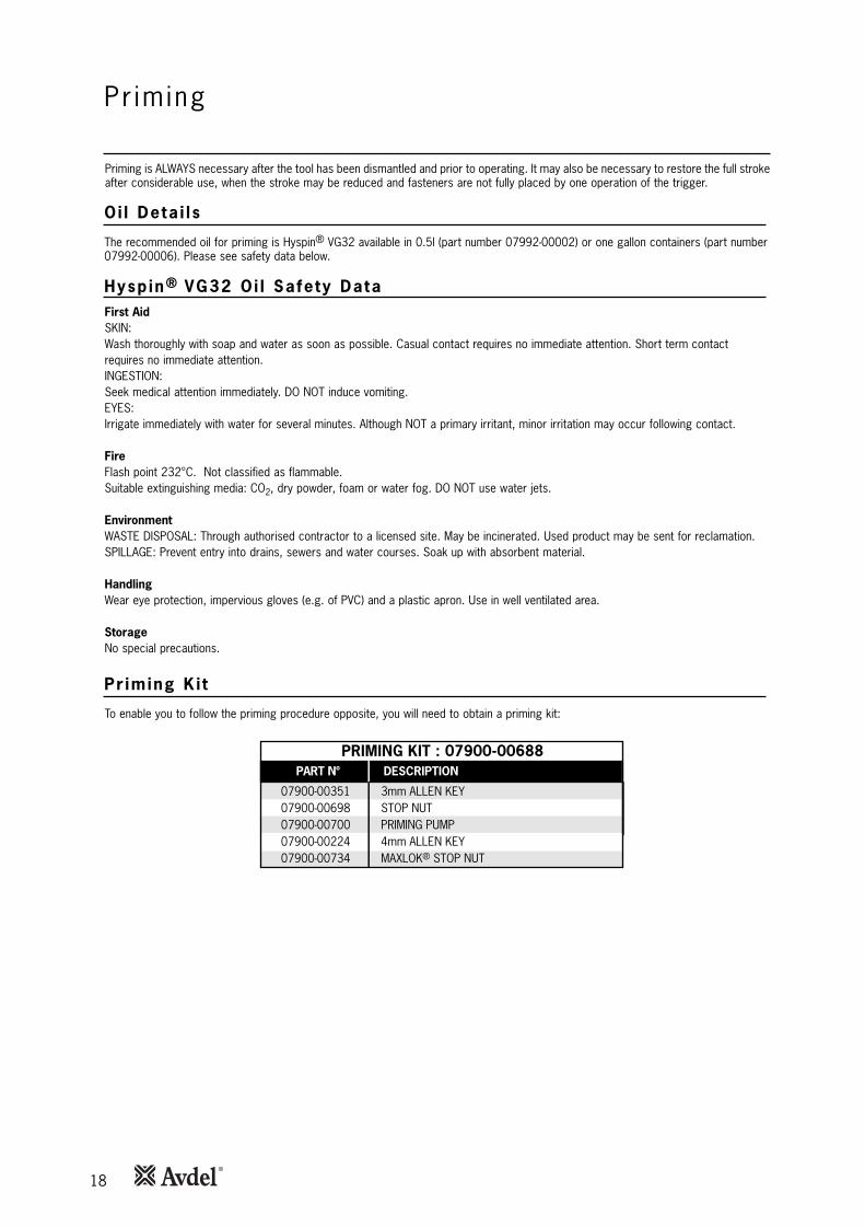
18
Pr im ing
Oi l Deta i l s
Hysp in® VG32 Oi l Safety Data
Pr iming K i t
To enable you to follow the priming procedure opposite, you will need to obtain a priming kit:
PART Nº DESCRIPTION
PRIMING KIT : 07900-00688
07900-00351 3mm ALLEN KEY07900-00698 STOP NUT07900-00700 PRIMING PUMP07900-00224 4mm ALLEN KEY07900-00734 MAXLOK® STOP NUT
Priming is ALWAYS necessary after the tool has been dismantled and prior to operating. It may also be necessary to restore the full strokeafter considerable use, when the stroke may be reduced and fasteners are not fully placed by one operation of the trigger.
The recommended oil for priming is Hyspin® VG32 available in 0.5l (part number 07992-00002) or one gallon containers (part number07992-00006). Please see safety data below.
First AidSKIN:Wash thoroughly with soap and water as soon as possible. Casual contact requires no immediate attention. Short term contactrequires no immediate attention.INGESTION:Seek medical attention immediately. DO NOT induce vomiting.EYES:Irrigate immediately with water for several minutes. Although NOT a primary irritant, minor irritation may occur following contact.
FireFlash point 232°C. Not classified as flammable.Suitable extinguishing media: CO2, dry powder, foam or water fog. DO NOT use water jets.
EnvironmentWASTE DISPOSAL: Through authorised contractor to a licensed site. May be incinerated. Used product may be sent for reclamation.SPILLAGE: Prevent entry into drains, sewers and water courses. Soak up with absorbent material.
HandlingWear eye protection, impervious gloves (e.g. of PVC) and a plastic apron. Use in well ventilated area.
StorageNo special precautions.

19
I M P O R T A N T
DISCONNECT THE TOOL FROM THE AIR SUPPLY OR SWITCH OFF AT VALVE 55. REMOVE NOSE ASSEMBLY.
All operations should be carried out on a clean bench, with clean hands in a clean area.Ensure that the new oil is perfectly clean and free from air bubbles.
Care MUST be taken at all times, to ensure that no foreign matter enters the tool, or serious damage may result.
• Remove bleed Screw 9 and Bonded Seal 10.
• Connect air supply to tool and switch ON/OFF Valve Assembly 60 to "ON” position.
• Invert tool over suitable container and actuate trigger. Waste oil will be ejected through the bleed screw hole.
CARE SHALL BE TAKEN TO ENSURE THAT THE BLEED HOLE IS NOT DIRECTED TOWARDS THE OPERATOR OR OTHERPERSONNEL.
• Screw stop nut 07900-00734 onto Chuck Collet Adaptor 1.
• Disconnect air supply to tool or switch ON/OFF Valve Assembly 60 to ‘OFF” position.
• Fill the priming pump with oil.
• Screw priming pump 07900-00700 into the bleed screw hole with Bonded Seal 10 in place.
• Actuate the priming pump by pressing down and releasing several times until resistance is felt.
• Remove the priming pump and the stop nut.
• Replace bleed Screw 9 and Bonded Seal 10.
• Connect air supply to tool and switch ON/OFF Valve Assembly 60 to ‘ON” position.
• Check that the stroke of the tool meets the minimum specification of 13 millimetres. To check the stroke, measure the distancebetween the front face of Chuck Collet Adaptor 1 and the front face of the head, BEFORE pressing the trigger and when thetrigger is fully actuated. The stroke is the difference between the two measurements. If it does not meet the minimumspecification, repeat the priming procedure.
Item numbers in bold refer to the General Assembly drawing and Parts List on pages 16-17.
P r im ingPr iming Procedure

20
Fau l t D iagnos is
Symptom Poss ib le Cause Remedy Page Ref
Item numbers in bold refer to the General Assembly drawing and Parts List on pages 16-17.
More than one Air leak Tighten joints or replace components
operation of the Insufficient air pressure Adjust air pressure to within specification 5
trigger needed to Worn or broken jaws Fit new jaws 9
place fastener Low oil level or air in oil Prime tool 18-19
Build up of dirt inside the nose assembly Service 9
Tool will not grip Worn or broken jaws Fit new jaws 9
stem of fastener Build up of dirt inside the nose assembly Service 9
Loose jaw housing or chuck collet Tighten against locking ring 9
Weak or broken spring in nose assembly Fit new spring 9
Incorrect component in nose assembly Identify and replace 9
Jaws will not release Build up of dirt inside the nose assembly Service 12
broken stem of chuck collet.
fastener Tighten nose assembly 9
Weak or broken spring in nose assembly Fit new spring 8-9
Air or oil leak Tighten joints or replace components
Low oil level or air present in oil Prime tool 18-19
Cannot feed next Broken stems jammed inside tool Empty stem collector 4 (point 14)
fastener Check correct equipment is fitted 8-9
Adjust air pressure to within specification 5
Slow cycle Low air pressure Adjust air pressure to within the specification 5
Build up of dirt inside the nose assembly Service 12
Tool fails to operate No air pressure Connect and adjust to within the specification 5
Damaged Trigger Valve 46 Replace 15
Loose stem collector Tighten Retaining Nut 26 15
Fastener fails to break Insufficient air pressure Adjust air pressure to within specification 5
Fastener outside tool capability Use more powerful Genesis tool.
Contact Avdel UK Limited
Low oil level or air present in oil Prime tool 18-19
Tool fails to swage Insufficient air pressure Adjust air pressure to within specification 5
collar Worn or damaged anvil Replace 8-9
Low oil level or air present in oil Prime tool 18-19
Other symptoms or failures should be reported to your local Avdel® authorised distributor or repair centre.

21
Notes

22
Notes
23
Dec lara t ion o f Conformi ty
We, Avdel UK Limited, Watchmead Industrial Estate, Welwyn Garden City, Herts, AL7 1LYdeclare under our sole responsibility that the product:
Model G2LB
Serial No. ................................................
to which this declaration relates is in conformity with the following standards:
EN ISO 12100 - parts 1 & 2BS EN ISO 8662 - part 6 BS EN ISO 11202BS EN ISO 3744 BS EN 982ISO EN 792 part 13 - 2000 BS EN 983
following the provisions of the Machine Directive 2006/42/EC.
This box contains a power tool which is inconformity with Machines Directive2006/42/EC. The ‘Declaration of Conformity’is contained within.
Date of issue
A. Seewraj - Product Engineering Manager - Automation Tools

Since 1 936 2010 Since 1922
www.avdel-global.comwww.infastech.com
02.2
011
• ©
201
0 In
fast
ech
Autosert® (equipment), Avbolt ®, Avdel®, Avdelmate®, Avdel TX2000®, Avdelok®, Avex®, Avibulb®, Avinox®, Avinut™, Avlug®, Avmatic®, Avplas®,Avseal®, Avsert®, Avtainer®, Avtronic®, Briv®, Bulbex®, Chobert®, Eurosert®, Fastriv®, Finsert®, Genesis®, Grovit®, Hemlok®, Hexsert®, Holding your world together®, Hydra®, Interlock®, Klamp-Tite®, Klamptite KTR®, Kvex®, Maxlok®, Monobolt®, Monobulb ®, Neobolt®, Nutsert®, Nutsert SQ®, Portariv®, Rivmatic®, Rivscrew®, Speed Fastening®, Squaresert®, Stavex®, Supersert®, Thin Sheet Nutsert®, Titan®, T-Lok®, TLR®, TSN®, TX2000®, Versa-Nut®, Viking® and Viking 360® are trademarks of Avdel UK Limited. Infastech™ and Our Technology, Your Success™ are trademarks of Infastech Intellectual Properties Pte Ltd. The names and logos of other companies mentioned herein may be trademarks of their respective owners. This document is for informational purposes only. Infastech makes no warranties, expressed or implied, in this document. Data shown is subject to change without prior notice as a result of continuous product development and improvement policy. Your local Avdel representative is at your disposal should you need to confirm latest information.
AUSTRALIAInfastech (Australia) Pty Ltd.891 Wellington RoadRowvilleVictoria 3178Tel: +61 3 9765 6400Fax: +61 3 9765 [email protected]
CANADAAvdel Canada Limited1030 Lorimar DriveMississaugaOntario L5S 1R8Tel: +1 905 364 0664Fax: +1 905 364 [email protected]
CHINAInfastech (China) Ltd.RM 1708, 17/F., Nanyang Plaza,57 Hung To Rd., Kwun TongHong KongTel: +852 2950 0631Fax: +852 2950 [email protected]
FRANCEAvdel France S.A.S.33 bis, rue des ArdennesBP4 75921 Paris Cedex 19Tel: +33 (0) 1 4040 8000Fax: +33 (0) 1 4208 [email protected]
GERMANYAvdel Deutschland GmbHKlusriede 2430851 LangenhagenTel: +49 (0) 511 7288 0Fax: +49 (0) 511 7288 [email protected]
INDIAInfastech Fastening Technologies India Private LimitedPlot No OZ-14, Hi Tech SEZ,SIPCOT Industrial Growth Center,Oragadam, Sriperumbudur Taluk, Kanchipuram District,602105 TamilnaduTel: +91 44 4711 8001Fax: +91 44 4711 [email protected]
ITALYAvdel Italia S.r.l.Viale Lombardia 51/5320047 Brugherio (MI)Tel: +39 039 289911Fax: +39 039 [email protected]
JAPANInfastech Kabushiki KaishaCenter Minami SKY, 3-1 Chigasaki-Chuo, Tsuzuki-ku,Yokohama-city, Kanagawa PrefectureJapan 224-0032Tel: +81 45 947 1200Fax: +81 45 947 [email protected]
MALAYSIAInfastech (Malaysia) Sdn BhdLot 63, Persiaran Bunga Tanjung 1,Senawang Industrial Park70400 SerembanNegeri SembilanTel: +606 676 7168Fax: +606 676 [email protected]
SINGAPOREInfastech (Singapore) Pte Ltd. 31 Kaki Bukit Road 3#05-03/06 TechlinkSingapore, 417818Tel: +65 6372 5653Fax: +65 6744 [email protected]
SOUTH KOREAInfastech (Korea) Ltd.212-4, Suyang-Ri,Silchon-Eup, Kwangju-City,Kyunggi-Do, Korea, 464-874Tel: +82 31 798 6340Fax: +82 31 798 [email protected]
SPAIN Avdel Spain S.A.C/ Puerto de la Morcuera, 14Poligono Industrial Prado OveraCtra. de Toledo, km 7,828919 Leganés (Madrid)Tel: +34 91 3416767Fax: +34 91 [email protected]
TAIWANInfastech/Tri-Star LimitedNo 269-7, Baodong Rd, Guanmiao Township,71841 Tainan County,Taiwan, R.O.CTel: +886 6 596 5798 (ext 201)Fax: +886 6 596 [email protected]
UNITED KINGDOMAvdel UK LimitedPacific House2 SwiftfieldsWatchmead Industrial EstateWelwyn Garden CityHertfordshire AL7 1LYTel: +44 (0) 1707 292000Fax: +44 (0) 1707 [email protected]
USAAvdel USA LLC614 NC Highway 200 SouthStanfield, North Carolina 28163Tel: +1 704 888 7100Fax: +1 704 888 [email protected]
Manual No. Issue Change Note No. Date
A 04/065 06/04
B 07/044 02/07
B2 07-103 03/07
B3 08-096 07/08
B4 11/061 03/11
07900-00834