Embed Size (px)
Citation preview
ManualFurlex 100 S
595-102-E2014-08-14
100 S
2
� To derive the maximum benefit and enjoyment from your Furlex system, we recommend that you study this manual carefully.
� The manual is divided into two sections, one dealing with ASSEMBLY and one with OPERATION. Each section contains references to the other. It is very important to read and note these cross references.
� All safety-related information is indicated by the following symbol:
� The manual covers one Furlex size, 100 S. The model designation can be found on the line drum top.
� Furlex is specified and manufactured using Metric dimensions. To assist owners unfamiliar with this system, the approximate equivalent Imperial dimensions are given in brackets.
� The screws used for the halyard swivel and lower bearing assembly have a Torx socket. The Torx type socket has an excellent grip but is not yet in common use. The necessary torx bits are included with the Furlex. The Torx socket sizes are:
This information must be followed to avoid damage to the system and the risk of personal injury. The 2-year guarantee on the Furlex system is only valid if the system is assembled and operated correctly according to the manual.
1 Introduction
PLEASE read the entire manual prior to assembly!
Seldén Mast AB guarantees the Furlex system for 2 years. The guarantee covers faults arising from defective design, materials or workmanship.
The guarantee is only valid if the Furlex system is assembled, operated and maintained in accordance with this manual and is not subjected to loads in excess of those indicated in the brochure and instructions.
Complete shipment and warranty conditions are to be found on Seldéns website www.seldenmast.com.See Resources/Partners information/General information/General conditions of sale (595-546-E).
If the system is repaired by anyone other than Seldén Mast AB or one of our authorized dealers, the guarantee ceases to be valid.
Seldén Mast AB reserves the right to alter the content and design without prior warning.
Torx SocketScrew SizeM5 T 25M6 T 30M8 T 40 Fig. 1.1.a
1.1 The manual

3
1 Introduction 1.1 The manual 2 1.2 Product information 4
ASSEMBLY2 Checklist 2.1 Furlex box 6 2.2 Foil pack 8 2.3 Tools 8
3 Assembly preparations 3.1 Forestay attachment - guiding principle 9 3.2 Mast attachment 9 3.3 Deck attachment 9 3.3.1 Dimension of lower bearing assembly 10 3.3.2 Dimension of top eye terminal 10 3.3.3 Table of measurements for toggles 11 3.4 Assembly below deck 123.5 Calculating the length of the forestay wire 133.5.1 Table 1: Calculation of forestay wire length 133.6 Calculating the length of the luff extrusion 143.6.1 Table 2: Calculation of luff extrusion length 14
4 Assembly of the Furlex-system4.1 Assembly of the luff section 164.2 Fitting the wire terminal 174.3 Fitting the line drum and line guide 20
5 Halyard routing 5.1 Halyard leads 225.2 Halyard sheave box 235.2.1 Sheave boxes 235.3 Spinnaker halyard 235.4 Fitting the halyard lead 23
6 Furling line arrangement6.1 Functional description 256.2 Winding the line onto the line drum 256.3 Routing of the furling line 266.4 Fitting the stanchion blocks 27
7 The Sail 7.1 Adapting the sail to the Furlex system 287.1.1 Table of sail measurements 297.2 Sail shape 297.3 Determining the length of the pendant 30
OPERATION 31 10 Halyard routing10.1 Summary 3210.2 Halyard sheave box 3310.3 Spinnaker halyard 33
11 Sailing with Furlex11.1 To hoist the sail 3411.2 Unfurling the sail 3511.3 Furling the sail 36
12 Reefing12.1 Free turn 3712.2 Reefing under sail 3712.3 Setting a reefed sail from the furled position 3812.4 Adjusting the sheeting position 38
13 Furlex for racing 39
14 Adjusting the forestay length14.1 Furlex with rigging screw 4014.1.1 Rigging Screw adjustment 4014.2 Furlex without rigging screw 41
15 Maintaining your Furlex system15.1 Lubricating the lower bearing assembly 4215.2 Lubricating the halyard swivel 4215.3 Cleaning the Furlex 4315.4 Storage 43
16 Rigging16.1 Fitting the Furlex on a stepped mast 4416.2 Stepping the mast with Furlex fitted 45
17 Dismantling17.1 Halyard swivel 4617.2 Sail feeder 4617.3 Line guide / Line drum 4717.4 Forestay 4817.5 Lower bearing assembly 4917.6 Luff extrusion system 49
18 Troubleshooting 50
19 Checklist19.1 Points to check before sailing 52
ContentsPagePage
4
When the original Furlex was introduced in 1983, it was not a pioneering project. The design included features which improved on other manufacturers’ products to increase performance, function and reliability. The first systems sold are still functioning well, providing ample proof of the design’s effectiveness and long-term staying power. Furlex quickly became the market leader, a position it still occupies today. Our success can also be put down to how we select a system for a specific yacht. First we calculate the boat’s righting moment, which is a function of its displacement, ballast, beam and draft. Then we use righting moment in combination with the rig type to calculate its power when sailing, and the likely loads on the Furlex system.
Furlex is only sold through authorized local dealers who are able to cover all service requirements for the customer, including assistance with assembly, the modification of sails or the production of new sails.
This new Furlex model range incorporates improvements based on our extensive experience, and represents the very latest development of the jib furling and reefing concept.
� Furlex is supplied as a complete assembly kit containing all the components required.
� The ball-bearing system of the halyard swivel features a load distribution facility, a unique patented system which distributes loads over the entire ball race. This permits smoother furling and considerably reduces bearing wear.
� Furlex 100 S for Ø 6 mm forestay can be supplied with an optional external rigging screw.
� The Furlex luff section has the same dimensions over its whole length. The entire luff is furled in an even roll, right down to the tack of the sail. This is a requirement for satisfactory sail shape when reefed.
� The tack ring’s ”free turn” flattens out the sail, promoting an efficient shape when reefed.
� Furlex is suited to both cruising and racing. The line drum and line guide are easy to remove if you want to utilize the entire forestay length for racing.
� The luff section has two luff grooves, allowing two jibs to be goose-winged when running down-wind and facilitating fast sail changes for racing yachtsmen.
� The prefeeder is always on hand to help when hoisting the sail.
� The line guide fitting centres the line as it is wound onto the drum, and the flexible internal line guard maintains light pressure on the line to ensure even distribution on the drum.
� Furlex is manufactured by Seldén Mast, the world’s leading manufacturer of masts and rigging systems.
1.2 Product information
Follow the instructions carefully when fitting.

5
1. Forestay /eye terminal 2. Top guard 3. Halyard swivel 4. Snap shackle 5. Luff extrusion 6. Distance tube 7. Joining sleeve 8. Sail feeder 9. Sail feeder connector 10. Lower bearing assembly
11. Tack ring12. Adapter13. Fork / fork toggle14. Line drum flange halves15. Line guard housing16. Line guard 17. Line guard bracket18. Line guide fitting19. Prefeeder
1
2
3
4
5
9
8
7
6
12
11
1419
4
13
10
16
18
17
15
6
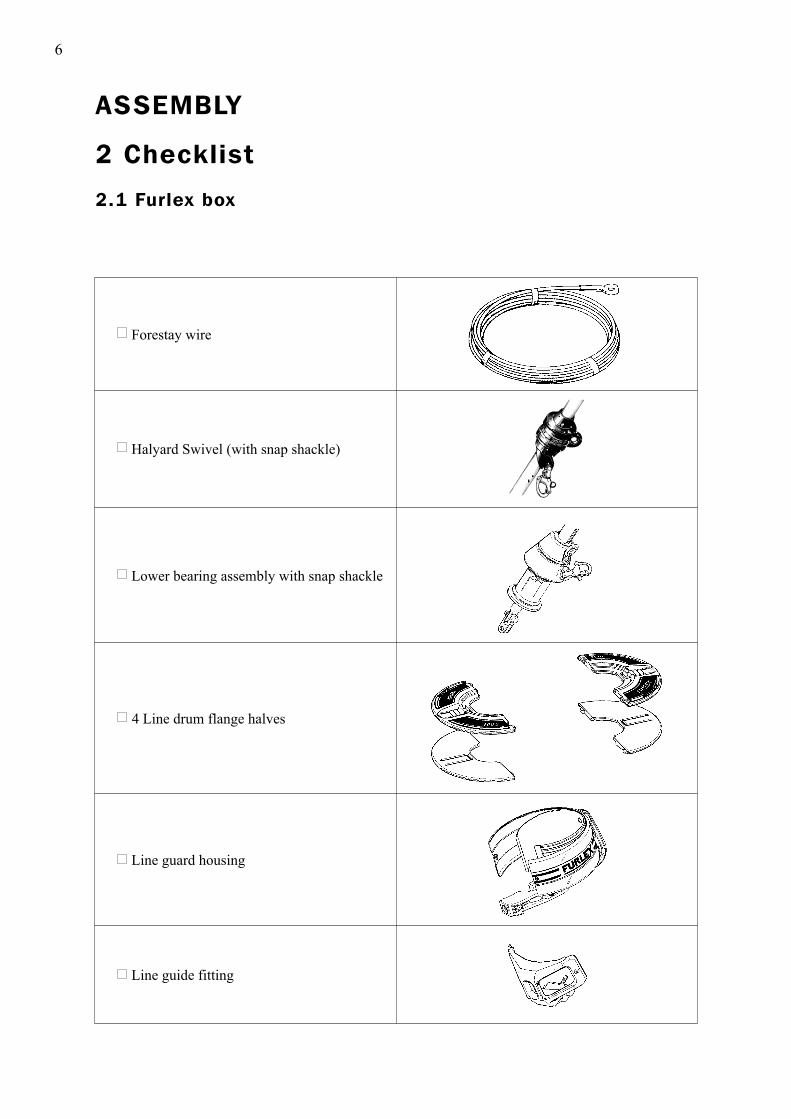
2 Checklist
2.1 Furlex box
Forestay wire
Halyard Swivel (with snap shackle)
Lower bearing assembly with snap shackle
4 Line drum flange halves
Line guard housing
Line guide fitting
ASSEMBLY

7
2 halyard leads 508-135 with insulator sheets incl. 4 screws
Torx bit set (T15/20/25/30/40/45)
4 stanchion blocks
Top guard incl. 2 screws
Instructions Spare parts list Certificate of guarantee
Furling line
Drill bit Ø 5.3 mm (7/32”)
Prefeeder incl. shock cord and hook
Locking adhesive Lubricating grease

8
Tools needed for assembly: Screwdriver (standard tip) Screwdriver for 1/4” bits Hacksaw 2 adjustable spanners Pair of pliers (“Polygrip”) Adhesive tape File Marker pen (water-proof) Torx bits (included in Furlex package) Steel measuring tape (20 m) (60’7”) Knife For halyard leads: Heavy-duty Philips screwdriver Drill Drill bit Ø 5.3 mm (7/32”) (included in package)
2.3 Tools
One x 1000 mm (39 3/8”) luff extrusion with long joint sleeve.
One x 2000 mm (78 3/4”) luff extrusion with distance tube.
2400 mm (94 1/2”) luff extrusions with distance tube + joint sleeves. (Number dependent on length ordered).
Sail feeder (sail feeder + sailfeeder connector.)
One long connecting spring for each 2400 mm (94 1/2”) and 2000 mm (78 3/4”) luff extrusion
One short connecting spring for the 1000 mm (39 3/8”) luff extrusion
2.2 Foil pack:
9
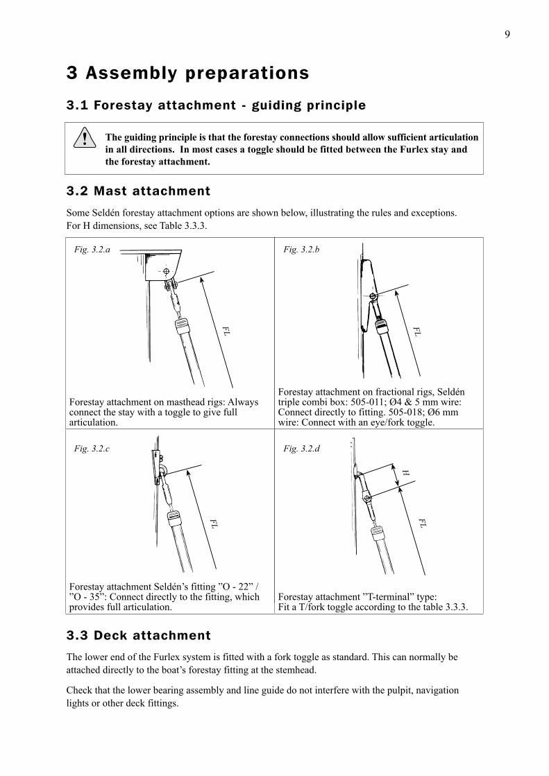
Forestay attachment on masthead rigs: Always connect the stay with a toggle to give full articulation.
Forestay attachment on fractional rigs, Seldén triple combi box: 505-011; Ø4 & 5 mm wire: Connect directly to fitting. 505-018; Ø6 mm wire: Connect with an eye/fork toggle.
Forestay attachment Seldén’s fitting ”O - 22” / ”O - 35”: Connect directly to the fitting, which provides full articulation.
Forestay attachment ”T-terminal” type:Fit a T/fork toggle according to the table 3.3.3.
3 Assembly preparations
3.1 Forestay attachment - guiding principle
Some Seldén forestay attachment options are shown below, illustrating the rules and exceptions. For H dimensions, see Table 3.3.3.
The lower end of the Furlex system is fitted with a fork toggle as standard. This can normally beattached directly to the boat’s forestay fitting at the stemhead.
Check that the lower bearing assembly and line guide do not interfere with the pulpit, navigation lights or other deck fittings.
Fig. 3.2.a Fig. 3.2.b
Fig. 3.2.c Fig. 3.2.d
The guiding principle is that the forestay connections should allow sufficient articulation in all directions. In most cases a toggle should be fitted between the Furlex stay and the forestay attachment.
FL
FL
FL
H
FL
3.2 Mast attachment
3.3 Deck attachment
10
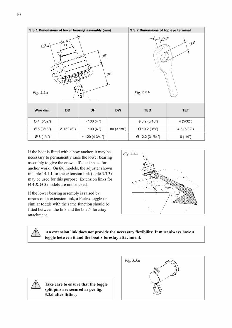
3.3.1 Dimensions of lower bearing assembly (mm) 3.3.2 Dimensions of top eye terminal
Wire dim. DD DH DW TED TET
Ø 4 (5/32”)
Ø 152 (6”)
~ 100 (4 ”)
80 (3 1/8”)
ø 8.2 (5/16”) 4 (5/32”)
Ø 5 (3/16”) ~ 100 (4 ”) Ø 10.2 (3/8”) 4.5 (5/32”)
Ø 6 (1/4”) ~ 120 (4 3/4 ”) Ø 12.2 (31/64”) 6 (1/4”)
If the boat is fitted with a bow anchor, it may be necessary to permanently raise the lower bearing assembly to give the crew sufficient space for anchor work. On Ø6 models, the adjuster shown in table 14.1.1, or the extension link (table 3.3.3) may be used for this purpose. Extension links for Ø 4 & Ø 5 models are not stocked.
If the lower bearing assembly is raised by means of an extension link, a Furlex toggle or similar toggle with the same function should be fitted between the link and the boat’s forestay attachment.
Fig. 3.3.c
An extension link does not provide the necessary flexibility. It must always have a
toggle between it and the boat´s forestay attachment.
Fig. 3.3.a Fig. 3.3.b
Take care to ensure that the toggle
split pins are secured as per fig. 3.3.d after fitting.
Fig. 3.3.d
TEDTET
DD
DW
DH
20°

11
Toggle typeForestay Dimensions
Ø 4 (5/32”) Ø 5 (3/16”) Ø 6 (1/4”)
Article no. 174-102 174-103 174-104
Length (H) 25 (1”) 35 (1 3/8”) 40 (1 1/2”)
Ø Eye (D1) 8 (5/16”) 10 (3/8”) 11 (7/16”)
Ø Clevis pin (D2) 8 (5/16”) 9,5 (3/8”) 11 (7/16”)
Fork width (W2) 8 (5/16”) 10 (3/8”) 12 (1/2”)
Article no. 517-056-02 517-054-02 517-046-02
Length (H) 25 (1”) 30 (1 3/16”) 40 (1 1/2”)
Ø Clevis pin (D1) 8 (5/16”) 10 (3/8”) 12 (1/2”)
Fork width (W1) 7,5 (9/32”) 10 (3/8”) 11 (7/16”)
Ø Clevis pin (D2) 8 (5/16”) 10 (3/8”) 10 (3/8”)
Fork width (W2) 8 (5/16”) 11 (7/16”) 11 (7/16”)
Article no. 174-127 174-128 174-122
Length (H) 60 (2 3/8”) 70 (2 3/4”) 80 (3 1/4”)
Ø Clevis pin (D2) 8 (5/16”) 9,5 (3/8”) 11 (7/16”)
Fork width (W2) 8 (5/16”) 10 (3/8”) 12 (1/2”)
Article no. - 517-065-01 517-066-01
Length (H) - 138 (5 7/16”) 152 (6”)
Ø Stemball (D1) - 26 (1 1/32”) 26 (1 1/32”)
Height (HB) - 8,5 (1/3”) 8 (5/16”)
Radius (R) - 10 (3/8”) 10 (3/8”)
Ø Clevis pin (D2) - 10 (3/8”) 10 (3/8”)
Fork width (W2) - 11 (7/16”) 11 (7/16”)
Article no. - - 517-063-01
Length (H) - - 90 (3 9/16”)
Ø Clevis pin (D1) - - 12 (1/2”)
Fork width (W1) - - 11 (7/16”)
Ø Eye (D2) - - 12 (1/2”)
Gauge (W2) - - 6 (1/4”)
Furlex-rigging screw, see chap. 14.
W2
HB
H
R
D1
D2
11
3.3.3 Table of measurements for toggles(Toggles available from your Furlex dealer)
Eye / fork toggle
Fig. 3.3.e
Fig. 3.3.f
Fork / Fork toggle
Fig. 3.3.g
T / fork toggle
H
D2
W2
Fig. 3.3.h
H
D2
W2
D1
D2
W2
H
D1
W1
Stemball / Eye toggle
with Fork / fork toggle
Eye / fork Extension link
Fig. 3.3.i
D2
H
W2
D1
W1
Fig. 3.3.j
12
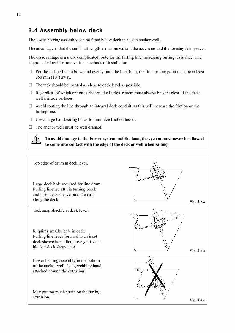
The lower bearing assembly can be fitted below deck inside an anchor well.
The advantage is that the sail’s luff length is maximized and the access around the forestay is improved.
The disadvantage is a more complicated route for the furling line, increasing furling resistance. The diagrams below illustrate various methods of installation.
� For the furling line to be wound evenly onto the line drum, the first turning point must be at least 250 mm (10”) away.
� The tack should be located as close to deck level as possible.
� Regardless of which option is chosen, the Furlex system must always be kept clear of the deck well’s inside surfaces.
� Avoid routing the line through an integral deck conduit, as this will increase the friction on the furling line.
� Use a large ball-bearing block to minimize friction losses.
� The anchor well must be well drained.
To avoid damage to the Furlex system and the boat, the system must never be allowed
to come into contact with the edge of the deck or well when sailing.
Top edge of drum at deck level.
Large deck hole required for line drum. Furling line led aft via turning block and inset deck sheave box, then aft along the deck.
Tack snap shackle at deck level.
Requires smaller hole in deck. Furling line leads forward to an inset deck sheave box, alternatively aft via a block + deck sheave box.
Lower bearing assembly in the bottom of the anchor well. Long webbing band attached around the extrusion
May put too much strain on the furling extrusion.
Fig. 3.4.a
Fig. 3.4.b
Fig. 3.4.c.
3.4 Assembly below deck
13
Deduction for lower wire terminal: Ø 4 mm wire: – 45 mm (1 3/4”) Ø 5 mm wire: – 55 mm (2 5/32”) Ø 6 mm wire: – 70 mm (2 3/4”)
T
Existing forestay length (FL), including rigging screw (See fig. 3.5.a)FL
=
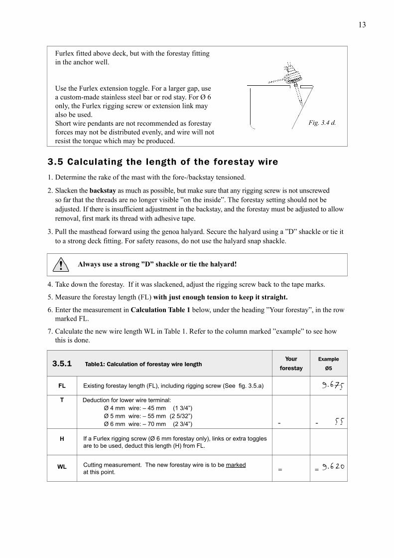
Furlex fitted above deck, but with the forestay fitting in the anchor well.
Use the Furlex extension toggle. For a larger gap, use a custom-made stainless steel bar or rod stay. For Ø 6 only, the Furlex rigging screw or extension link may also be used. Short wire pendants are not recommended as forestay forces may not be distributed evenly, and wire will not resist the torque which may be produced.
1. Determine the rake of the mast with the fore-/backstay tensioned.
2. Slacken the backstay as much as possible, but make sure that any rigging screw is not unscrewed so far that the threads are no longer visible ”on the inside”. The forestay setting should not be adjusted. If there is insufficient adjustment in the backstay, and the forestay must be adjusted to allow removal, first mark its thread with adhesive tape.
3. Pull the masthead forward using the genoa halyard. Secure the halyard using a ”D” shackle or tie it to a strong deck fitting. For safety reasons, do not use the halyard snap shackle.
Always use a strong ”D” shackle or tie the halyard!
4. Take down the forestay. If it was slackened, adjust the rigging screw back to the tape marks.
5. Measure the forestay length (FL) with just enough tension to keep it straight.
6. Enter the measurement in Calculation Table 1 below, under the heading ”Your forestay”, in the row marked FL.
7. Calculate the new wire length WL in Table 1. Refer to the column marked ”example” to see how this is done.
Your
forestay
Example
Ø5 Table1: Calculation of forestay wire length 3.5.1
H
WL
If a Furlex rigging screw (Ø 6 mm forestay only), links or extra toggles are to be used, deduct this length (H) from FL.
Cutting measurement. The new forestay wire is to be marked
at this point.
- - 190
= 13100
Fig. 3.4 d.
9.675
55
9.620
3.5 Calculating the length of the forestay wire

14
If the top extrusion is shorter than 400 mm (15 3/4”), the joint will be too near the top. In this case replace the uppermost full- length 2400 mm extrusion with the 2000 mm extrusion. In this way the joint is moved 400mm (15 3/4”) down the stay. Adjust the C and D measurements as follows:
Deduct 400 mm (15 3/4”) from the C measurement. Add 400 mm (15 3/4”) to the D measurement.
-
1. Insert the length of the new forestay wire (WL) as calculated in table 1 into table 2, in the row marked WL.
2. Calculate the number of full length extrusions and the length of the top extrusion.
Fixed deduction (A+B):
C+D=
3.6.1
WL
A+B
C+D
C
D
Max. number of 2400 mm (7’ 10 1/2”) extrusions which together are
shorter than C+D: [ ............ x 2400 = C ]
C=
Length of top extrusion = The top extrusion is normally cut from the 2000 mm extrusion.
Round the edges of the cut end using a file.
Ø 4 mm wire: E = D – 120 mm (4 3/4”) Ø 5 mm wire: E = D – 120 mm (4 3/4”) Ø 6 mm wire: E = D – 200 mm (7 7/8”)
Cut the distance tube for the top extrusion in accordance with the following fixed deduction:
E
Deduction:
Length of distance tube E = - =
Table 2: Calculation of luff extrusion length
Length of new forestay wire (as per Table 1)
Your
extrusionExample
Ø 5
-1395 =1395
–1395(3 extrusions)
-
= 2115
=
Ø 4 mm wire: – 1340 mm (4’ 4 3/4”)Ø 5 mm wire: – 1340 mm (4’ 4 3/4”)Ø 6 mm wire: – 1290 mm (4’ 2 3/4”)
9.620
1.3408.280
7.200
1.080
120960
3.6 Calculating the length of the luff extrusion

15 15
FL = Existing forestay length
Fig. 3.5.a
AE
C
B
D
WL
T

16
Insert one end of a 144 mm (5 11/16”) spring in the upper hole of the 1000 mm extrusion, and slide the long joining sleeve up to hold it in place. Remove the 200 mm (7 7/8”) joining sleeve from a 2400 mm (94 1/2 ”) extrusion. This will be used later in the 2000 mm (78 3/4”) extrusion. Connect the 2400 mm extrusion and the 1000 mm extrusion. Push the long joining sleeve up into the 2400 mm extrusion to secure the connection spring. Continue pushing until the bottom of the sleeve is 50mm inside lower end of the 1000 mm extrusion. A 50 mm (2”) gap is formed at this joint (as shown in fig. 4.1.c.), where the sail feeder is to be fitted later.
Fit the short connecting spring (L=103 mm/4 1/8”) to the 1000 mm (39 3/8”) extrusion. The larger hook must be on the free end. Push the long joining sleeve (L=1168 mm/46”) down, to hold the spring in place and make space for the next spring.
Connect the remaining extrusions as detailed in table 3.6.1.
Fig. 4.1.a
Fig. 4.1.c
Fig. 4.1.d
1.
2.
4.
3.
Assembly should be carried out on a horizontal surface. Connect the luff extrusions one by one,starting at the lower bearing assembly.
90 mm (3 9/16”) 20 mm (13/16”)
The extrusions are then fitted to the adapter of the lower bearing assembly. Hook the connecting spring to the internal hole in the adapter. Then push the distance tube in the 2400 mm extrusion down so that the joining sleeve bottoms in the adapter. The distance tube should be buried approximately 100 mm (4”), about equal to half a length of a joining sleeve.
≈ 50 mm (≈2”)
≈ 100 mm (≈2”)
Fig. 4.1.b
4 Assembly of the Furlex System
4.1 Assembly of the luff section
17
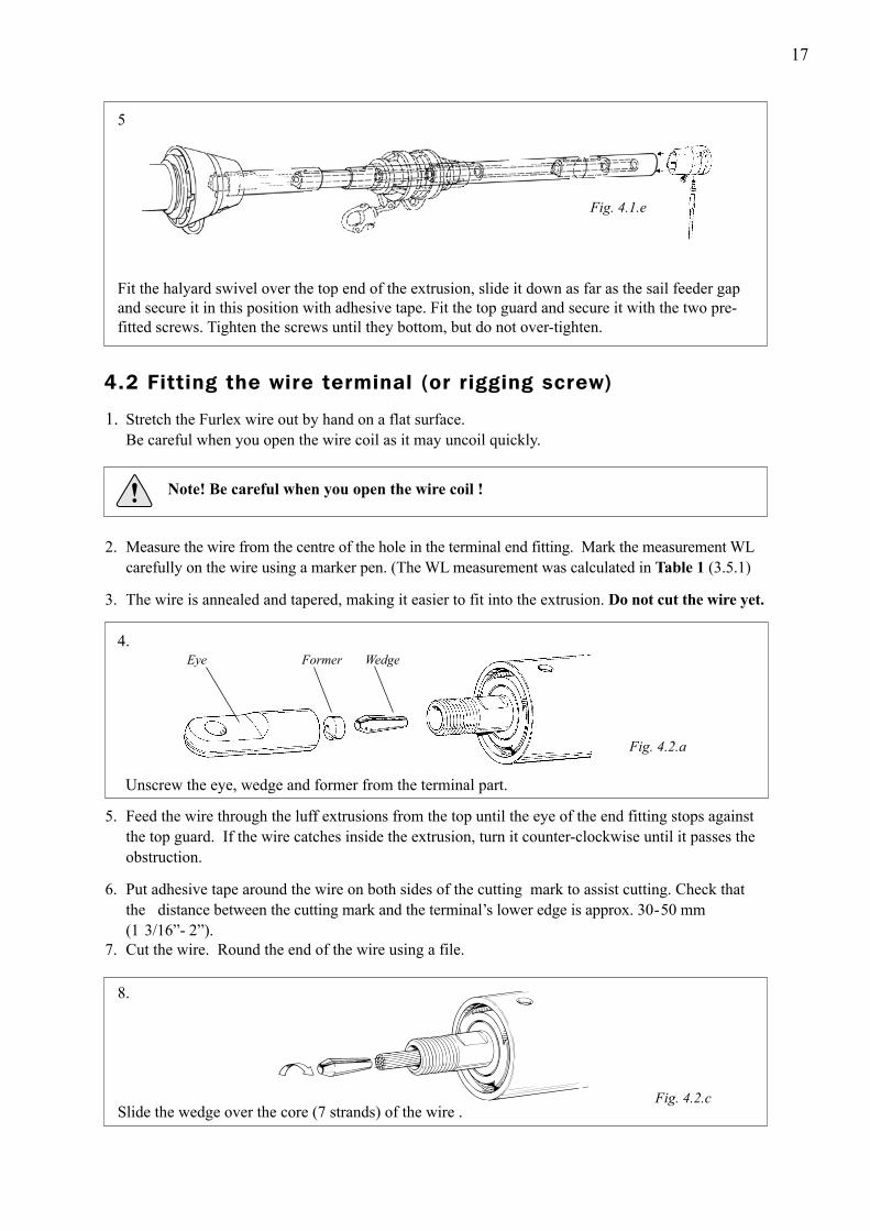
Fit the halyard swivel over the top end of the extrusion, slide it down as far as the sail feeder gap and secure it in this position with adhesive tape. Fit the top guard and secure it with the two pre- fitted screws. Tighten the screws until they bottom, but do not over-tighten.
5
1. Stretch the Furlex wire out by hand on a flat surface. Be careful when you open the wire coil as it may uncoil quickly.
Note! Be careful when you open the wire coil !
2. Measure the wire from the centre of the hole in the terminal end fitting. Mark the measurement WL carefully on the wire using a marker pen. (The WL measurement was calculated in Table 1 (3.5.1)
3. The wire is annealed and tapered, making it easier to fit into the extrusion. Do not cut the wire yet.
5. Feed the wire through the luff extrusions from the top until the eye of the end fitting stops against the top guard. If the wire catches inside the extrusion, turn it counter-clockwise until it passes the obstruction.
6. Put adhesive tape around the wire on both sides of the cutting mark to assist cutting. Check that the distance between the cutting mark and the terminal’s lower edge is approx. 30-50 mm (1 3/16”- 2”).7. Cut the wire. Round the end of the wire using a file.
4.
Unscrew the eye, wedge and former from the terminal part.
Fig. 4.2.a
Fig. 4.2.c
8.
Slide the wedge over the core (7 strands) of the wire .
Eye Former Wedge
Fig. 4.1.e
4.2 Fitting the wire terminal (or rigging screw)

18
9.
The core of the wire should protrude approx. 2 mm (3/32”) from the wedge. Space the outer strands of the wire evenly around the wedge and push it into the socket so that the strands are held in place. Tap the wire lightly so the outerstrands jam in the seat.
NOTE! Check that no strands slip into the slot of the wedge.
Fig. 4.2.d
10. Bend the outer strands inwards a little using a pair of pliers, or tap the strands with a small hammer. In the latter case, rest the socket’s thread on a soft surface (wood or similar) to prevent damage.
12.
Unscrew and check that the outer strands are evenly distributed around the wedge. If some strands are crossed, correct their positions.
NOTE! Check that no strand has slipped into the slot of the wedge!
13. If assembly is unsuccessful and needs to be repeated, refer to the relevant sections of chap. 17, ”Dismantling”.
Fig. 4.2.f
11.
Insert the former into the threaded hole of the eye part (or rigging screw). Lubricate the socket´s thread with a long bead of locking adhesive. Screw the terminal part onto the socket and tighten carefully, forcing the wire further into the terminal.
Fig. 4.2.e
14.
Apply 2 or 3 drops of the locking adhesive to the thread and screw the terminal together, tightening it firmly. The terminal is now permanently locked.
Fig. 4.2.g
2 mm
19
15:1 15:2
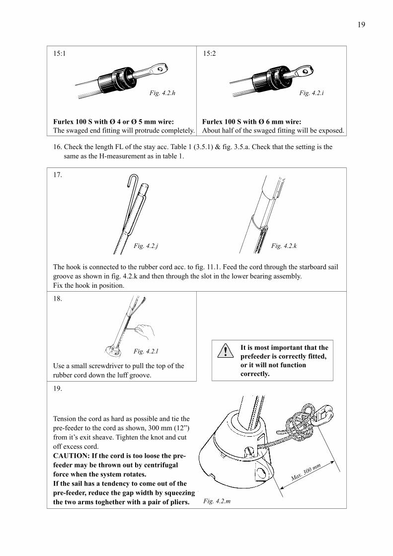
Furlex 100 S with Ø 4 or Ø 5 mm wire: The swaged end fitting will protrude completely.
Furlex 100 S with Ø 6 mm wire: About half of the swaged fitting will be exposed.
Fig. 4.2.h Fig. 4.2.i
17.
18.
19.
Fig. 4.2.l
16. Check the length FL of the stay acc. Table 1 (3.5.1) & fig. 3.5.a. Check that the setting is the same as the H-measurement as in table 1.
The hook is connected to the rubber cord acc. to fig. 11.1. Feed the cord through the starboard sail groove as shown in fig. 4.2.k and then through the slot in the lower bearing assembly. Fix the hook in position.
Use a small screwdriver to pull the top of the rubber cord down the luff groove.
Fig. 4.2.j Fig. 4.2.k
It is most important that the prefeeder is correctly fitted, or it will not function correctly.
Tension the cord as hard as possible and tie the pre-feeder to the cord as shown, 300 mm (12”) from it’s exit sheave. Tighten the knot and cut off excess cord. CAUTION: If the cord is too loose the pre- feeder may be thrown out by centrifugal force when the system rotates. If the sail has a tendency to come out of the pre-feeder, reduce the gap width by squeezing the two arms toghether with a pair of pliers.
Max. 300 mm
Fig. 4.2.m

20
20.
21.
Installing the sail feeder:
22. We recommend fitting the Furlex system onto the boat at this stage. See chap. 16, ”Rigging”.
Press on the sail feeder connector from the front of the luff extrusion.
Clip the sail feeder into the connector’stop recess, then press the sail feeder’s lower edge until it snaps into place.
Fig. 4.2.n
Fig. 4.2.o
4.3 Fitting the line drum and line guide
These parts are easier to fit after the Furlex is fitted to the boat.
1.
2.
Fig. 4.3.c
Fit the two upper flange halves (with the labels) on the lower bearing.
Feed the furling line through the hole in the line guide fitting and into the oval hole in the lower bearing assembly until it is just past the small sighting hole. Tighten the locking screw hard.
Fig. 4.3.a Fig. 4.3.b
1
21
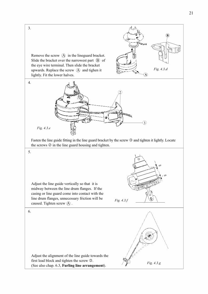
Fasten the line guide fitting in the line guard bracket by the screw and tighten it lightly. Locate the screws in the line guard housing and tighten.
4.
5.
Fig. 4.3.e
Adjust the line guide vertically so that it is midway between the line drum flanges. If the casing or line guard come into contact with the line drum flanges, unnecessary friction will be caused. Tighten screw A .
6.
Fig. 4.3.f
=
=
3.
Fig. 4.3.d
Remove the screw A in the lineguard bracket. Slide the bracket over the narrowest part B of the eye wire terminal. Then slide the bracket upwards. Replace the screw A and tighen it lightly. Fit the lower halves.
Adjust the alignment of the line guide towards the first lead block and tighten the screw . (See also chap. 6.3, Furling line arrangement).
2
3
Fig. 4.3.g
B
A

22
May lead to
5 Halyard routing The angle between the halyard and the forestay must be 5 - 10° - see fig. 5.4.c. If this angle is less, thehalyard may wrap around the luff section when the sail is being furled, possibly damaging the halyard and the luff extrusion. Failure to observe what is happening in this situation may even result in damage to the forestay wire.
Incorrect halyard routing can promote ”Halyard wrap” which may cause severe
damage to the forestay, and put the entire rig at risk. If the sail is furled with the aid of a winch, take great care. It can be difficult to control the tension on the furling line.
Fig. 5.a Fig. 5.b
To avoid halyard wrap, 2 halyard leads are included in the Furlex kit. These are easy to fit and are suitable for all makes of mast. When sailing, movement occurs between the wire halyard and the halyard lead. To prevent halyard wear, the halyard lead is made of bronze. This is ”softer” than a wire halyard, so the halyard lead will wear before the wire. Halyard leads should be inspected once a year and any sharp edges smoothed with a file. The halyard lead should be replaced when wear reaches 50%. The halyard leads are not covered by the 2 year Furlex - warranty.
5.1 Halyard leads
23
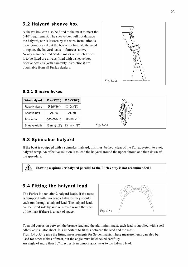
Wire Halyard
Sheave box Rope Halyard
Ø 4 (5/32”) Ø 5 (3/16”)
Ø 8(5/16”)
AL-45
Ø10(3/8”)
AL-70
Article no. 505-004-10 505-006-10
Sheave width 13 mm(1/2”) 13 mm(1/2”)
5.2.1 Sheave boxes
If the boat is equipped with a spinnaker halyard, this must be kept clear of the Furlex system to avoidhalyard wrap. An effective solution is to lead the halyard around the upper shroud and then down aft the spreaders.
Stowing a spinnaker halyard parallel to the Furlex stay is not recommended !
The Furlex kit contains 2 halyard leads. If the mastis equipped with two genoa halyards they should each run through a halyard lead. The halyard leads can be fitted side by side or moved round the side of the mast if there is a lack of space.
To avoid corrosion between the bronze lead and the aluminium mast, each lead is supplied with a self-adhesive insulator sheet. It is important to fit this between the lead and the mast. Figs. 5.4.c-5.4.e give the fitting measurements for Seldén masts. These measurements can also be used for other makes of mast, but the angle must be checked carefully. An angle of more than 10° may result in unnecessary wear to the halyard lead.
Fig. 5.4.a
Fig. 5.2.b
A sheave box can also be fitted to the mast to meet the 5-10° requirement. The sheave box will not damage the halyard, nor is it worn by the wire. Installation is more complicated but the box will eliminate the need to replace the halyard leads in future as above.Newly manufactured Seldén masts on which Furlex is to be fitted are always fitted with a sheave box. Sheave box kits (with assembly instructions) are obtainable from all Furlex dealers.
Fig. 5.2.a
5.4 Fitting the halyard lead
5.3 Spinnaker halyard
5.2 Halyard sheave box
24
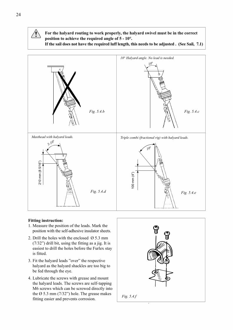
Fig. 5.4.b Fig. 5.4.c
Fig. 5.4.e Fig. 5.4.d
Fitting instruction:1. Measure the position of the leads. Mark the position with the self-adhesive insulator sheets.
2. Drill the holes with the enclosed Ø 5.3 mm (7/32”) drill bit, using the fitting as a jig. It is easiest to drill the holes before the Furlex stay is fitted.
3. Fit the halyard leads ”over” the respective halyard as the halyard shackles are too big to be fed through the eye. 4. Lubricate the screws with grease and mount the halyard leads. The screws are self- tapping M6 screws which can be screwed directly into the Ø 5.3 mm (7/32”) hole. The grease makes fitting easier and prevents corrosion. Fig. 5.4.f
10° Halyard angle. No lead is needed.
Masthead with halyard leads. Triple combi (fractional rig) with halyard leads.
10°
5-10°
210
mm
(8 5
/16”
)
For the halyard routing to work properly, the halyard swivel must be in the correct position to achieve the required angle of 5 - 10°. If the sail does not have the required luff length, this needs to be adjusted . (See Sail, 7.1)
100
mm
(4”)
10°
25
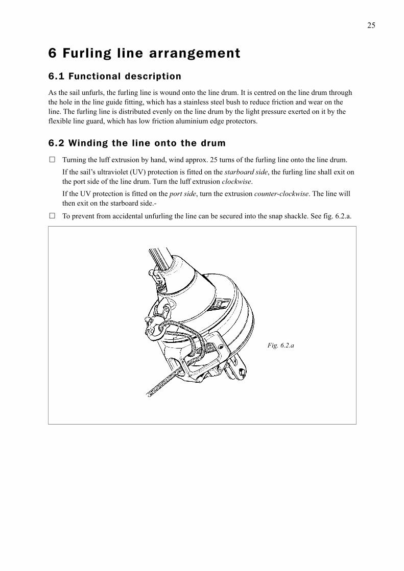
� Turning the luff extrusion by hand, wind approx. 25 turns of the furling line onto the line drum. If the sail’s ultraviolet (UV) protection is fitted on the starboard side, the furling line shall exit on the port side of the line drum. Turn the luff extrusion clockwise. If the UV protection is fitted on the port side, turn the extrusion counter-clockwise. The line will then exit on the starboard side.-
� To prevent from accidental unfurling the line can be secured into the snap shackle. See fig. 6.2.a.
Fig. 6.2.a
6.2 Winding the line onto the drum
6 Furling line arrangement
6.1 Functional description
As the sail unfurls, the furling line is wound onto the line drum. It is centred on the line drum throughthe hole in the line guide fitting, which has a stainless steel bush to reduce friction and wear on the line. The furling line is distributed evenly on the line drum by the light pressure exerted on it by the flexible line guard, which has low friction aluminium edge protectors.
26
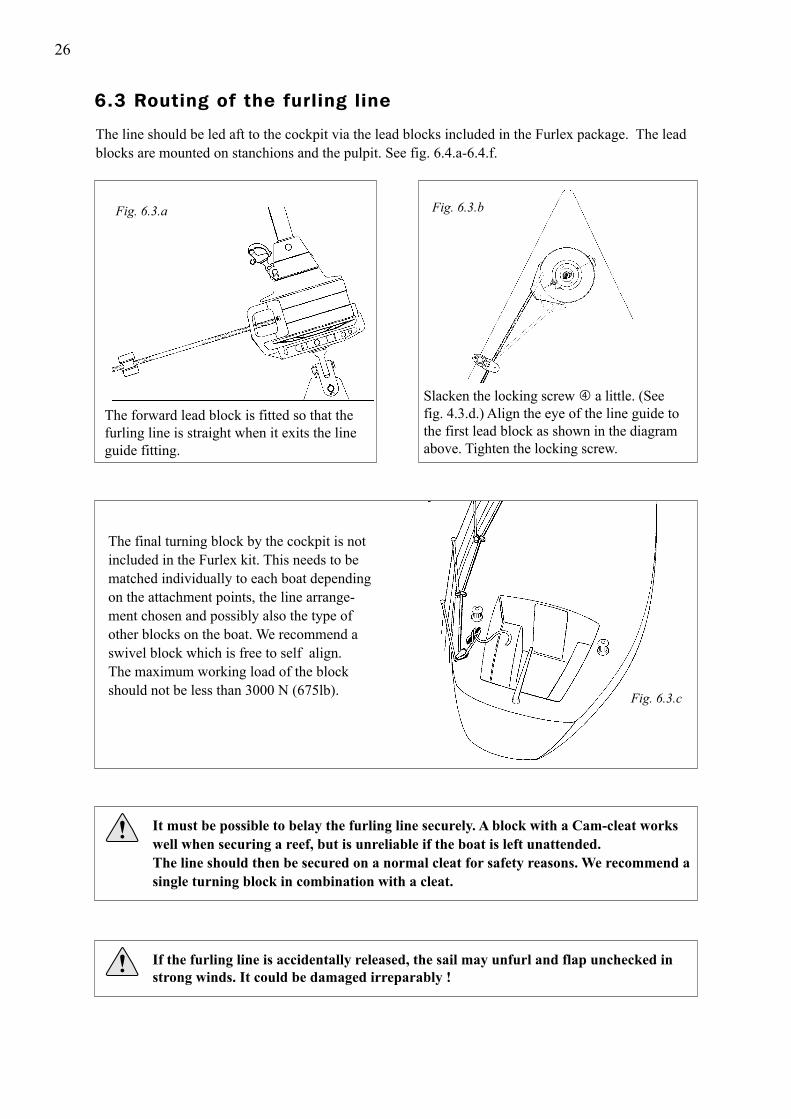
The forward lead block is fitted so that the furling line is straight when it exits the line guide fitting.
Slacken the locking screw a little. (See fig. 4.3.d.) Align the eye of the line guide to the first lead block as shown in the diagram above. Tighten the locking screw.
The line should be led aft to the cockpit via the lead blocks included in the Furlex package. The leadblocks are mounted on stanchions and the pulpit. See fig. 6.4.a-6.4.f.
The final turning block by the cockpit is not included in the Furlex kit. This needs to be matched individually to each boat depending on the attachment points, the line arrange- ment chosen and possibly also the type of other blocks on the boat. We recommend a swivel block which is free to self align. The maximum working load of the block should not be less than 3000 N (675lb).
It must be possible to belay the furling line securely. A block with a Cam-cleat works well when securing a reef, but is unreliable if the boat is left unattended. The line should then be secured on a normal cleat for safety reasons. We recommend a single turning block in combination with a cleat.
If the furling line is accidentally released, the sail may unfurl and flap unchecked in
strong winds. It could be damaged irreparably !
Fig. 6.3.a Fig. 6.3.b
Fig. 6.3.c
6.3 Routing of the furling line

27
1. 2
Insert the clamp halves into the sheave house as shown.
Squeeze the clamps together around the stanchion.
3. 4.
Screw the clamp halves together using the enclosed M6 screw and nut. Lightly tighten the screw.
Align the sheave house in the desired direction and tighten the M6 screw.
5. 6.
Thread the furling line and check the position. Finally, lock the block in position... … using the enclosed self-tapping screws.
The Furlex kit contains 4 stanchion blocks to be fitted to a 25 mm (1”) stanchion or pulpit. The blockhas a ball-and-socket joint and can be angled in any direction.
Fig. 6.4.a Fig. 6.4.b
Fig. 6.4.c Fig. 6.4.d
Fig. 6.4.e Fig. 6.4.f
6.4 Fitting the stanchion blocks

28
� To fit the Furlex system , an existing sail may need a number of modifications. The maximum luff length is calculated as shown in Table 7.1.1 and fig. 7.1.b. FL (F+E) (existing forestay length as per Table 3.5.1 - less head and tack deduction).
It is most important that the halyard swivel is located so that the halyard satisfies the 5 - 10° angle requirement. If the sail prevents the swivel from reaching the correct position, the luff length needs to be adjusted. IF THE SAIL IS TOO LONG: Shorten the sail, e.g. in conjunction with changing to a luff tape compatible with Furlex. IF THE SAIL IS TOO SHORT: Lengthen the sail by means of a wire pendant fitted to the head of the sail. Attach the pendant directly to the sail by a talurit splice to prevent unintentional removal, loss or exchange. All the boat’s foresails should be adjusted to the correct luff length. See 7.3 below ( There must be a minimum distance of 20 mm (3/4”) between the top of the halyard swivel and the top guard when the sail is fully tensioned.
� ”Cutback” for tack see table 7.1.1.
� The luff tape must be compatible with the Furlex luff extrusion. See luff extrusion measurements in table 7.1.1.
� If the sail is to be fitted with UV protection, this is best placed on the starboard side. The tack of the sail will then be in line with the luff grooves of the luff section when unrolled (see chap. 12, ”Reefing”). If the sail already has UV protection on the port side, the tack will be turned slightly to starboard. The free turn of the tack ring will function equally well.
� Use webbing loops at the sail head and tack instead of eyes (cringles). The sail will then form tightly round the luff extrusion when furling, and achieve a better shape when reefed.
7 The Sail
7.1 Adapting the sail to the Furlex system
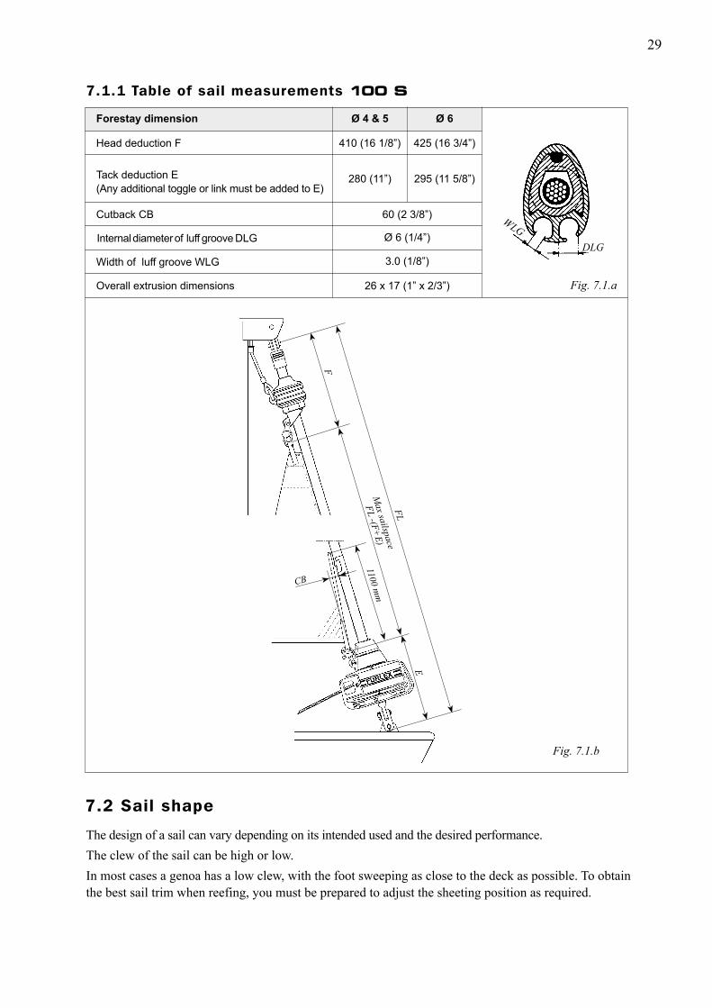
29
Ø 4 & 5 Forestay dimension Ø 6
Fig. 7.1.b
Cutback CB
Internal diameter of luff groove DLG
Width of luff groove WLG
Overall extrusion dimensions
60 (2 3/8”)
Ø 6 (1/4”)
3.0 (1/8”)
26 x 17 (1” x 2/3”)
280 (11”)
410 (16 1/8”)
295 (11 5/8”)
425 (16 3/4”)
Head deduction F
7.1.1 Table of sail measurements 100 S
Fig. 7.1.a
Tack deduction E (Any additional toggle or link must be added to E)
The design of a sail can vary depending on its intended used and the desired performance. The clew of the sail can be high or low. In most cases a genoa has a low clew, with the foot sweeping as close to the deck as possible. To obtain the best sail trim when reefing, you must be prepared to adjust the sheeting position as required.
Max sailspace
FL -(F+E)
FL
1100 mm
CB
E
F
WLG
DLG
7.2 Sail shape
30
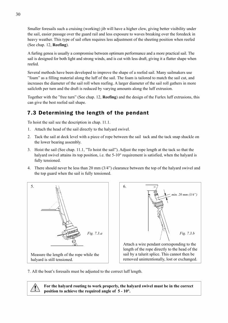
To hoist the sail see the description in chap. 11.1.1. Attach the head of the sail directly to the halyard swivel.
2. Tack the sail at deck level with a piece of rope between the sail tack and the tack snap shackle on the lower bearing assembly.
3. Hoist the sail (See chap. 11.1, ”To hoist the sail”). Adjust the rope length at the tack so that the halyard swivel attains its top position, i.e. the 5-10° requirement is satisfied, when the halyard is fully tensioned.
4. There should never be less than 20 mm (3/4”) clearance between the top of the halyard swivel and the top guard when the sail is fully tensioned.
7. All the boat’s foresails must be adjusted to the correct luff length.
For the halyard routing to work properly, the halyard swivel must be in the correct position to achieve the required angle of 5 - 10°.
Fig. 7.3.a Fig. 7.3.b
min. 20 mm (3/4”)
Measure the length of the rope while the halyard is still tensioned.
5. 6.
Attach a wire pendant corresponding to the length of the rope directly to the head of the sail by a talurit splice. This cannot then be removed unintentionally, lost or exchanged.
Smaller foresails such a cruising (working) jib will have a higher clew, giving better visibility under the sail, easier passage over the guard rail and less exposure to waves breaking over the foredeck in heavy weather. This type of sail often requires less adjustment of the sheeting position when reefed (See chap. 12, Reefing). A furling genoa is usually a compromise between optimum performance and a more practical sail. The sail is designed for both light and strong winds, and is cut with less draft, giving it a flatter shape when reefed. Several methods have been developed to improve the shape of a reefed sail. Many sailmakers use ”foam” as a filling material along the luff of the sail. The foam is tailored to match the sail cut, and increases the diameter of the sail roll when reefing. A larger diameter of the sail roll gathers in more sailcloth per turn and the draft is reduced by varying amounts along the luff extrusion. Together with the ”free turn” (See chap. 12, Reefing) and the design of the Furlex luff extrusions, this can give the best reefed sail shape.
7.3 Determining the length of the pendant
31
OPERATING MANUALTo derive the maximum benefit and enjoyment from your Furlex system, we recommend that you studythis operating manual carefully. All safety-related information is indicated by the following symbol.
Furlex is specified and manufactured using Metric dimensions. To assist owners unfamiliar with this system, the approximate equivalent Imperial dimension are given in brackets .
This information must be followed to avoid damage to the system and the risk of
personal injury. The 2 year guarantee on the Furlex system is only valid if the system is operated correctly according to the manual.
Unless you are fitting the Furlex system yourself, you do not need to read the entire assembly manual. However, there are references in the operating manual to certain sections of the assembly manual. It is very important to read and note these cross references.
Any additional fittings recommended in the manual are obtainable from your nearest Furlex dealer.
32
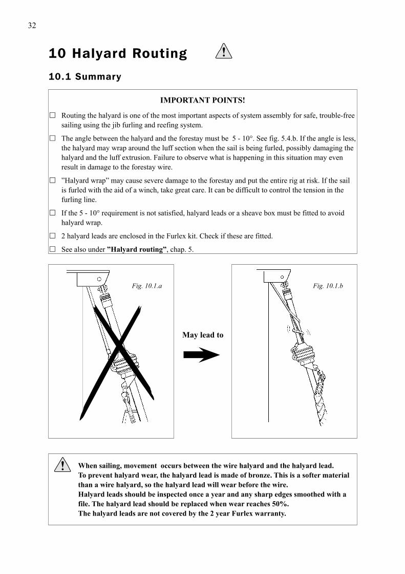
IMPORTANT POINTS!
� Routing the halyard is one of the most important aspects of system assembly for safe, trouble-free sailing using the jib furling and reefing system.
� The angle between the halyard and the forestay must be 5 - 10°. See fig. 5.4.b. If the angle is less, the halyard may wrap around the luff section when the sail is being furled, possibly damaging the halyard and the luff extrusion. Failure to observe what is happening in this situation may even result in damage to the forestay wire.
� ”Halyard wrap” may cause severe damage to the forestay and put the entire rig at risk. If the sail is furled with the aid of a winch, take great care. It can be difficult to control the tension in the furling line.
� If the 5 - 10° requirement is not satisfied, halyard leads or a sheave box must be fitted to avoid halyard wrap.
� 2 halyard leads are enclosed in the Furlex kit. Check if these are fitted.
� See also under ”Halyard routing”, chap. 5.
Fig. 10.1.bFig. 10.1.a
When sailing, movement occurs between the wire halyard and the halyard lead. To prevent halyard wear, the halyard lead is made of bronze. This is a softer material than a wire halyard, so the halyard lead will wear before the wire. Halyard leads should be inspected once a year and any sharp edges smoothed with a file. The halyard lead should be replaced when wear reaches 50%. The halyard leads are not covered by the 2 year Furlex warranty.
May lead to
10 Halyard Routing
10.1 Summary

33
A sheave box can also be fitted to the mast to meet the 5–10° requirement. A sheave box willnot damage the halyard nor is it worn by it either. Installation is more complicated but the box willeliminate the need to replace halyard leads in the future, as mentioned above.
When manufacturing Seldén masts, a sheave box is usally incorporated if a Furlex is to be used. Sheave box kits with fitting instructions are available from all Furlex dealers.
See also table 5.2.1 and fig. 5.2.a for further information.
If the boat is equipped with a spinnaker halyard, this must be kept clear of the Furlex system to avoidhalyard wrap. An effective solution is to lead the halyard around the upper shroud and then aft of the spreaders.
Stowing a spinnaker halyard parallel to the Furlex stay is not recommended!
10.2 Halyard sheave box
10.3 Spinnaker halyard
34
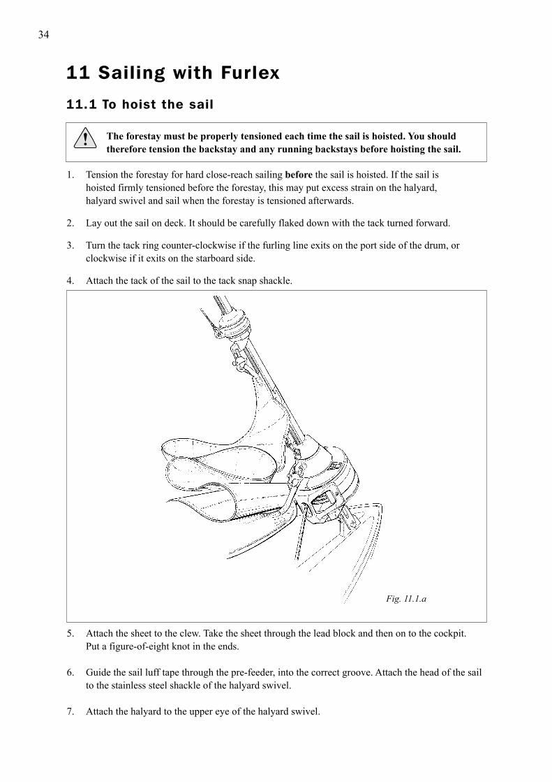
1. Tension the forestay for hard close-reach sailing before the sail is hoisted. If the sail is hoisted firmly tensioned before the forestay, this may put excess strain on the halyard, halyard swivel and sail when the forestay is tensioned afterwards. 2. Lay out the sail on deck. It should be carefully flaked down with the tack turned forward. 3. Turn the tack ring counter-clockwise if the furling line exits on the port side of the drum, or clockwise if it exits on the starboard side. 4. Attach the tack of the sail to the tack snap shackle.
The forestay must be properly tensioned each time the sail is hoisted. You should
therefore tension the backstay and any running backstays before hoisting the sail.
5. Attach the sheet to the clew. Take the sheet through the lead block and then on to the cockpit. Put a figure-of-eight knot in the ends. 6. Guide the sail luff tape through the pre-feeder, into the correct groove. Attach the head of the sail to the stainless steel shackle of the halyard swivel. 7. Attach the halyard to the upper eye of the halyard swivel.
Fig. 11.1.a
11 Sailing with Furlex
11.1 To hoist the sail
35
8. If the furling line exits on the port side of the line drum, the sail should be hoisted in the starboard groove. If the line exits on the starboard side, use the port groove. Hoisting the sail in the ”right” groove reduces initial resistance when furling the sail, which then has less of a ”fold” along the forestay than if the other groove is used.
9. Hoist the sail. The pre-feeder assists luff tape feed by steering the sail in towards the luff extrusion and sail feeder at a small angle. Tension the halyard until a vertical crease appears in the luff of the sail, then slacken off until the crease disappears. Belay the halyard.
10. The prefeeder will automaticly retract to it’s seat.
11. Furl the sail on the Furlex luff section by pulling on the furling line. Let the windward sheet run freely. Keep some tension in the leeward sheet, for example by placing a turn around a winch. It is important to furl the sail tightly and evenly, as a sail which is furled too loosely may blow out a little in strong winds. If the boat is left unattended, the sail may flap until it tears. A very loosely furled sail may also cause unnecessary wear, as the sail roll will swing back and forth in the wind.
12. Check the number of turns of the furling line remaining on the line drum. When the largest sail is furled tightly, there should be 3 - 5 turns left. To adjust the number of turns, detach the sheet and turn the Furlex luff extrusion by hand until the correct number of turns are on the drum. When furling in strong winds, the sail will roll more tightly, requiring more turns on the line drum and meaning that more line will be needed. Make sure you always have sufficient turns of line on the drum.
13. Check that the halyard swivel is at least 20 mm (3/4”) from the top guard and that the halyard angle satisfies the 5-10° requirement.
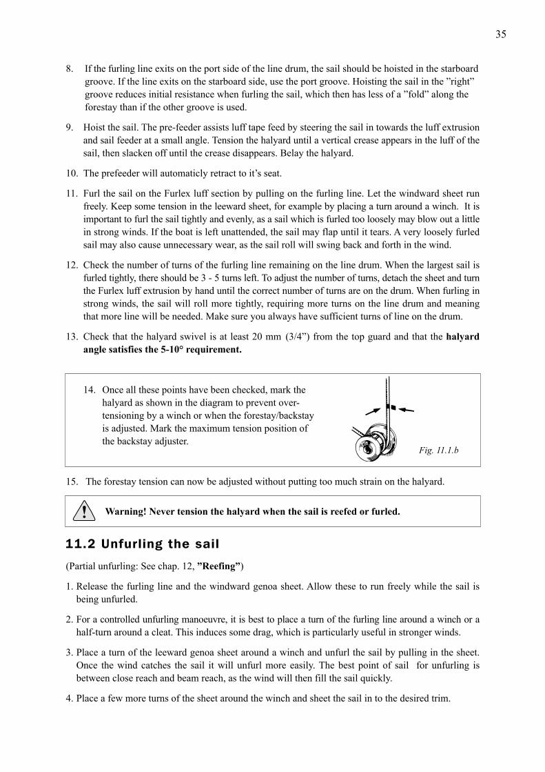
14. Once all these points have been checked, mark the halyard as shown in the diagram to prevent over- tensioning by a winch or when the forestay/backstay is adjusted. Mark the maximum tension position of the backstay adjuster.
15. The forestay tension can now be adjusted without putting too much strain on the halyard.
Warning! Never tension the halyard when the sail is reefed or furled.
(Partial unfurling: See chap. 12, ”Reefing”) 1. Release the furling line and the windward genoa sheet. Allow these to run freely while the sail is being unfurled. 2. For a controlled unfurling manoeuvre, it is best to place a turn of the furling line around a winch or a half-turn around a cleat. This induces some drag, which is particularly useful in stronger winds. 3. Place a turn of the leeward genoa sheet around a winch and unfurl the sail by pulling in the sheet. Once the wind catches the sail it will unfurl more easily. The best point of sail for unfurling is between close reach and beam reach, as the wind will then fill the sail quickly. 4. Place a few more turns of the sheet around the winch and sheet the sail in to the desired trim.
Fig. 11.1.b
11.2 Unfurling the sail
36
If the furling line is accidentally released, the sail may unfurl and flap unchecked in
strong winds. If left for any length of time, it could be damaged irreparably!
1. Release the windward sheet and ensure that it can run freely. 2. Furl the sail by pulling the furling line. Release the leeward sheet but keep a little tension on it, for example by placing a turn around a winch. It is important to furl the sail tightly and evenly, as a sail which is furled too loosely can blow out a little in strong winds. If the boat is left unattended, the sail may flap until it tears. A very loosely furled sail may also cause unnecessary wear, as the sail roll will swing back and forth in the wind. 3. Belay the furling line carefully. If the boat is left unattended, the furling line should be belayed on a cleat for safety.
If the boat is left for a fairly long period, it is a good idea to take down the sail and stow it below deck. It is then protected from UV radiation and dirt. Alternatively, a sail cover (“furling tube”) can be used to protect the sail.
11.3 Furling the sail
37
The size of the working sail area is infinitely variable with a jib furling and reefing system. Even if thesail is designed as a furling sail incorporating foam etc. and the Furlex system is equipped with a ”free turn” (see below), a reefed sail can never achieve the same efficiency as an unreefed sail of equal size. If the boat is equipped with more than one furling sail, these can be changed to suit the different wind conditions.
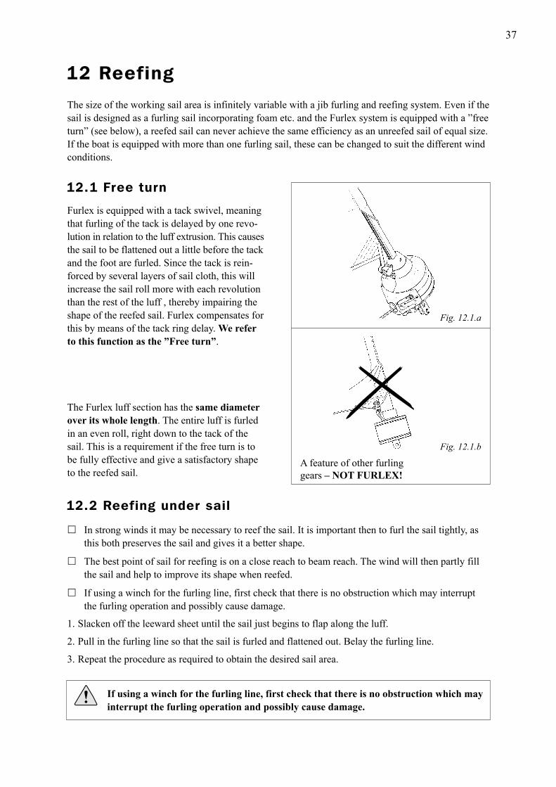
Fig. 12.1.a
The Furlex luff section has the same diameter over its whole length. The entire luff is furled in an even roll, right down to the tack of the sail. This is a requirement if the free turn is to be fully effective and give a satisfactory shape to the reefed sail.
Fig. 12.1.b
Furlex is equipped with a tack swivel, meaningthat furling of the tack is delayed by one revo-lution in relation to the luff extrusion. This causes the sail to be flattened out a little before the tack and the foot are furled. Since the tack is rein-forced by several layers of sail cloth, this will increase the sail roll more with each revolution than the rest of the luff , thereby impairing the shape of the reefed sail. Furlex compensates for this by means of the tack ring delay. We refer to this function as the ”Free turn”.
� In strong winds it may be necessary to reef the sail. It is important then to furl the sail tightly, as this both preserves the sail and gives it a better shape.
� The best point of sail for reefing is on a close reach to beam reach. The wind will then partly fill the sail and help to improve its shape when reefed.
� If using a winch for the furling line, first check that there is no obstruction which may interrupt the furling operation and possibly cause damage.
1. Slacken off the leeward sheet until the sail just begins to flap along the luff.
2. Pull in the furling line so that the sail is furled and flattened out. Belay the furling line.
3. Repeat the procedure as required to obtain the desired sail area.
If using a winch for the furling line, first check that there is no obstruction which may
interrupt the furling operation and possibly cause damage.
A feature of other furling gears – NOT FURLEX!
12.1 Free turn
12 Reefing
12.2 Reefing under sail

38
� You will achieve the best sail shape by first unfurling the sail completely and then reefing down to the appropriate size. Pull in the furling line and keep the sheet well tensioned. The sail will then form a tight roll and its shape will be improved.
� If the wind is too strong , or there are other reasons for not wanting to unfurl the sail completely, it can be reefed from the furled position. The sail should then be furled relatively tightly. The sail cannot be expected to have as good a shape when using this method. Wear on the sail is also increased.
When the sail is reefed, it may be necessary to adjust the sheeting position. For a sail with a low clew,the sheeting position has to be adjusted even when the sail is slightly reefed, a sail with a high clew requires less adjustment. See fig. 12.4.a. As a rule, however, you must be prepared to adjust the sheeting position as necessary to give the best sail trim.
Fig. 12.4.a
Adjustment of the sheeting position is made considerably easier if a floating sheet point arrangement is used. The traveller position is adjusted along the track by means of a line running through a block in the front of the track. The line is best routed to the cockpit where it is secured. The traveller position can also be adjusted under load with the aid of a winch.
Fig. 12.4.b
Many furling foresails have markings in the foot for different reefing positions. After you have tested combinations of sail area and sheeting position to see which function satisfactorily, you can use these markings as a reference and mark suitable sheet points on the track.
The angular variation of the sheet relative to the deck is less for a high-clewed sail. The comparison is based on the same number of furling revolutions.
Low clew High clew
12.3 Setting a reefed sail from the furled position
12.4 Adjusting the sheeting position

39
� Many racing yachtsmen have exploited the advantages of the jib furling and reefing system with reat success. The sail can be partly furled before the start, giving good visibility and easy manoeuvring of the boat. Just before starting, the sail is unfurled and the boat crosses the line under full sail. If the boat has a small crew, the advantages are obvious.
� The Furlex can be easily and quickly reconfigured from a furling jib system to a twin-groove racing headfoil. The line guide and line drum are dismantled without removing the forestay from the boat and the halyard swivel lowered below the sail feeder. When racing with a large crew, the sail can then be tacked at deck level, enabling the full hoisting length of the headfoil to be utilized. The twin luff grooves offer the option of quick sail changes.
Furlex is converted for racing by dismantling the line guide and line drum in the manner described under ”DISMANTLING” in chap. 17.3-17.4. The sail feeder is also removed (chap. 17.2 ) and the halyard swivel moved down to the lower bearing assembly. Re-fit the sail feeder and your Furlex is ready for racing!
Fig. 13.a
13 Furlex for racing

40
100S
Part.noAdjustment H1)Forestay dimension
Ø 4 (5/32”)
14 Adjusting the forestay length
Fig. 14.1.a
The Furlex 100 S for Ø 6 mm forestay may be supplied with or without an external rigging screw. For Ø 4 and Ø 5 mm forestay, there are no Furlex-rigging screw available.
The rigging screw has a stop at the maximum position to which it can be unscrewed.
Do not overload this stop by trying to unscrew the rigging screw further. The values given in the table below for adjustment must not be exceeded!
3. If the travel of the rigging screw is not sufficient, see below under ”Furlex without rigging screw”.
1. Place one wrench over the flat faces of the wire terminal and an other over the flat faces of the bronze nut.2. Adjust the position of the rigging screw by turning the bronze nut until the desired forestay length is obtained. The bronze nut does not require locking after adjustment.
14.1.1 Rigging screw adjustment
–
11850 (2”) 174-074-01
––
–––
Ø 6 (1/4”)
Ø 5 (3/16”)
Fig. 14.1.b
1) H=Increased length compared with standard Furlex. The H-dimension corresponds to rigging screw 50% extended.
H
On a system with a rigging screw, the forestay lengthcan be adjusted. This is the primary task of the rigging screw. Tensioning the forestay is best done with the backstay, which has a more favourable angle.The forestay length is adjusted as follows:
14.1 Furlex with rigging screw

41
If the Furlex system is not fitted with a rigging screw, the forestay can be lengthened by fitting extratoggles (See table 3.3.3). Several toggles are usually required to change the mast rake noticeably. These can be fitted at the upper or lower end of the system. On a Furlex with an Ø 6 mm (1/4”) forestay of the normal length (10600 mm) (34’9”), the masthead is moved 127 mm (5”) aft if the forestay is lengthened using a standard toggle H=40 mm (1 1/2”).
To shorten the Furlex system, the forestay wire and the luff extrusion must be shortened. See Dismantling, chap. 17 and Assembly of the Furlex System, chap. 4.
A Furlex 100 S with Ø 6 mm forestay can be retrofitted with a rigging screw. Contact your Furlex dealer.
NOTE! Never shorten the system by removing the lower Furlex toggle. (See Deck attachments, chap. 3.3).
14.2 Furlex without rigging screw
42
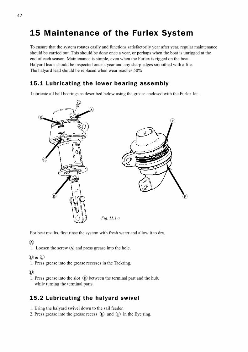
For best results, first rinse the system with fresh water and allow it to dry.
A1. Loosen the screw A and press grease into the hole.
B & C1. Press grease into the grease recesses in the Tackring.
D1. Press grease into the slot D between the terminal part and the hub, while turning the terminal parts.
To ensure that the system rotates easily and functions satisfactorily year after year, regular maintenanceshould be carried out. This should be done once a year, or perhaps when the boat is unrigged at the end of each season. Maintenance is simple, even when the Furlex is rigged on the boat.Halyard leads should be inspected once a year and any sharp edges smoothed with a file.The halyard lead should be replaced when wear reaches 50%
Fig. 15.1.a
Lubricate all ball bearings as described below using the grease enclosed with the Furlex kit.
1. Bring the halyard swivel down to the sail feeder.2. Press grease into the grease recess E and F in the Eye ring.
F
C
EB
A
D
15 Maintenance of the Furlex System
15.1 Lubricating the lower bearing assembly
15.2 Lubricating the halyard swivel

43
Wash and rinse the entire Furlex system with fresh water and a mild detergent to remove dirt and saltcrystals.
Note! Some detergents contain substances which can cause aluminium to corrode, so it is important to rinse all detergent off thoroughly. When the parts have dried, the anodized surfaces of the luff extrusions can be treated with a silicon-free boat polish or wax. This offers good protection and prevents particles of dirt from adhering and then soiling the sail. The stainless steel components can be treated with a suitable polish.
Fig. 15.4.a
Fig. 15.4.b
Under no circumstances should an unwashed or damp Furlex be wrapped in plastic or other impervious material.
In areas where frost can occur, the Furlex should be stored in a dry place or with it’s centre sections raised. This is to avoid ice damage to luff sections at sub-zero temperatures.
15.4 Storage
15.3 Cleaning the Furlex
The Furlex system is preferably stored with the mast during the winter.
44
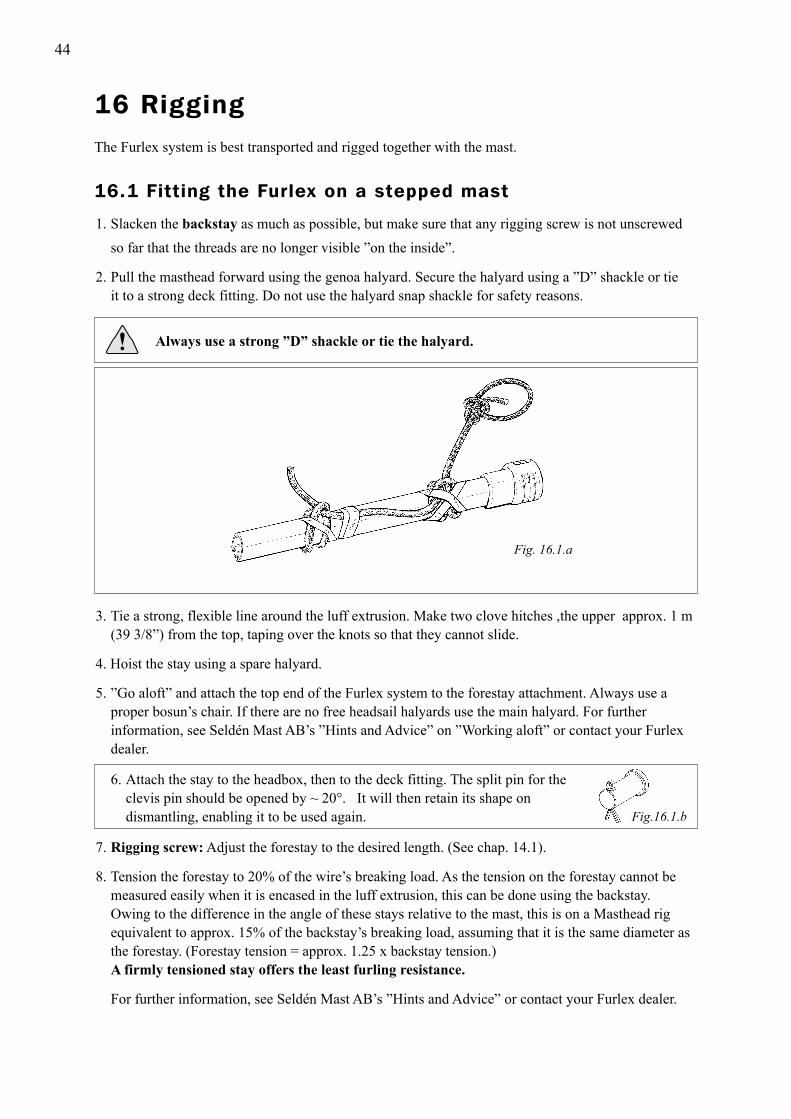
Always use a strong ”D” shackle or tie the halyard.
1. Slacken the backstay as much as possible, but make sure that any rigging screw is not unscrewed so far that the threads are no longer visible ”on the inside”.
2. Pull the masthead forward using the genoa halyard. Secure the halyard using a ”D” shackle or tie it to a strong deck fitting. Do not use the halyard snap shackle for safety reasons.
3. Tie a strong, flexible line around the luff extrusion. Make two clove hitches ,the upper approx. 1 m (39 3/8”) from the top, taping over the knots so that they cannot slide.
4. Hoist the stay using a spare halyard.
5. ”Go aloft” and attach the top end of the Furlex system to the forestay attachment. Always use a proper bosun’s chair. If there are no free headsail halyards use the main halyard. For further information, see Seldén Mast AB’s ”Hints and Advice” on ”Working aloft” or contact your Furlex dealer.
6. Attach the stay to the headbox, then to the deck fitting. The split pin for the clevis pin should be opened by ~ 20°. It will then retain its shape on dismantling, enabling it to be used again.
7. Rigging screw: Adjust the forestay to the desired length. (See chap. 14.1).
8. Tension the forestay to 20% of the wire’s breaking load. As the tension on the forestay cannot be measured easily when it is encased in the luff extrusion, this can be done using the backstay. Owing to the difference in the angle of these stays relative to the mast, this is on a Masthead rig equivalent to approx. 15% of the backstay’s breaking load, assuming that it is the same diameter as the forestay. (Forestay tension = approx. 1.25 x backstay tension.) A firmly tensioned stay offers the least furling resistance.
For further information, see Seldén Mast AB’s ”Hints and Advice” or contact your Furlex dealer.
Fig. 16.1.a
Fig.16.1.b
16.1 Fitting the Furlex on a stepped mast
The Furlex system is best transported and rigged together with the mast.
16 Rigging

45
Fig. 16.2.a
1. Lay the mast with the front uppermost.
2. Connect the top end of the Furlex system to the forestay attachment.
3. Lift the mast with the Furlex system lying on the leading edge of the mast.
4. Have one person watching the Furlex system to ensure that it does not get caught when lifting the mast. Keep the end of the stay outside the deck area in order to avoid damage.
5. Attach the stay to the boat as described in chap. 16.1 section 6 - 8.
16.2 Stepping the mast with Furlex fitted
46
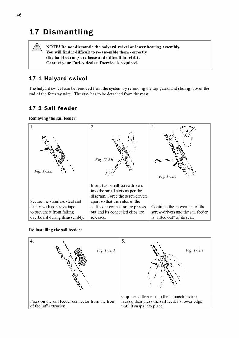
4. 5.
Press on the sail feeder connector from the front of the luff extrusion.
Clip the sailfeeder into the connector’s top recess, then press the sail feeder’s lower edge until it snaps into place.
1. 2. 3.
Secure the stainless steel sail feeder with adhesive tape to prevent it from falling overboard during disassembly.
Insert two small screwdrivers into the small slots as per the diagram. Force the screwdrivers apart so that the sides of the sailfeeder connector are pressed out and its concealed clips are released.
Continue the movement of the screw-drivers and the sail feeder is ”lifted out” of its seat.
17 Dismantling
NOTE! Do not dismantle the halyard swivel or lower bearing assembly.
You will find it difficult to re-assemble them correctly (the ball-bearings are loose and difficult to refit!) . Contact your Furlex dealer if service is required.
The halyard swivel can be removed from the system by removing the top guard and sliding it over theend of the forestay wire. The stay has to be detached from the mast.
Removing the sail feeder:
Fig. 17.2.b
Fig. 17.2.cFig. 17.2.a
Fig. 17.2.d Fig. 17.2.e
Re-installing the sail feeder:
17.2 Sail feeder
17.1 Halyard swivel
47
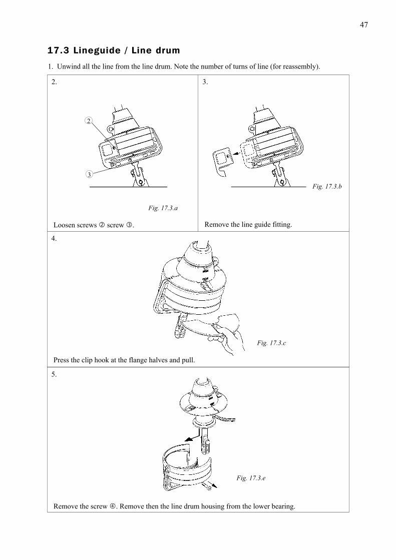
1. Unwind all the line from the line drum. Note the number of turns of line (for reassembly).
2. 3.
4.
Fig. 17.3.b
Fig. 17.3.a
Fig. 17.3.c
3
2
5.
Fig. 17.3.e
Remove the screw . Remove then the line drum housing from the lower bearing.
Press the clip hook at the flange halves and pull.
Loosen screws screw . Remove the line guide fitting.
17.3 Lineguide / Line drum
48
To shorten the wire or to remove it.
For a better understanding of the following instructions, we recommend that you first read the sectionon assembly on chap. 4.1.
1. Remove the toggles from the wire terminal.
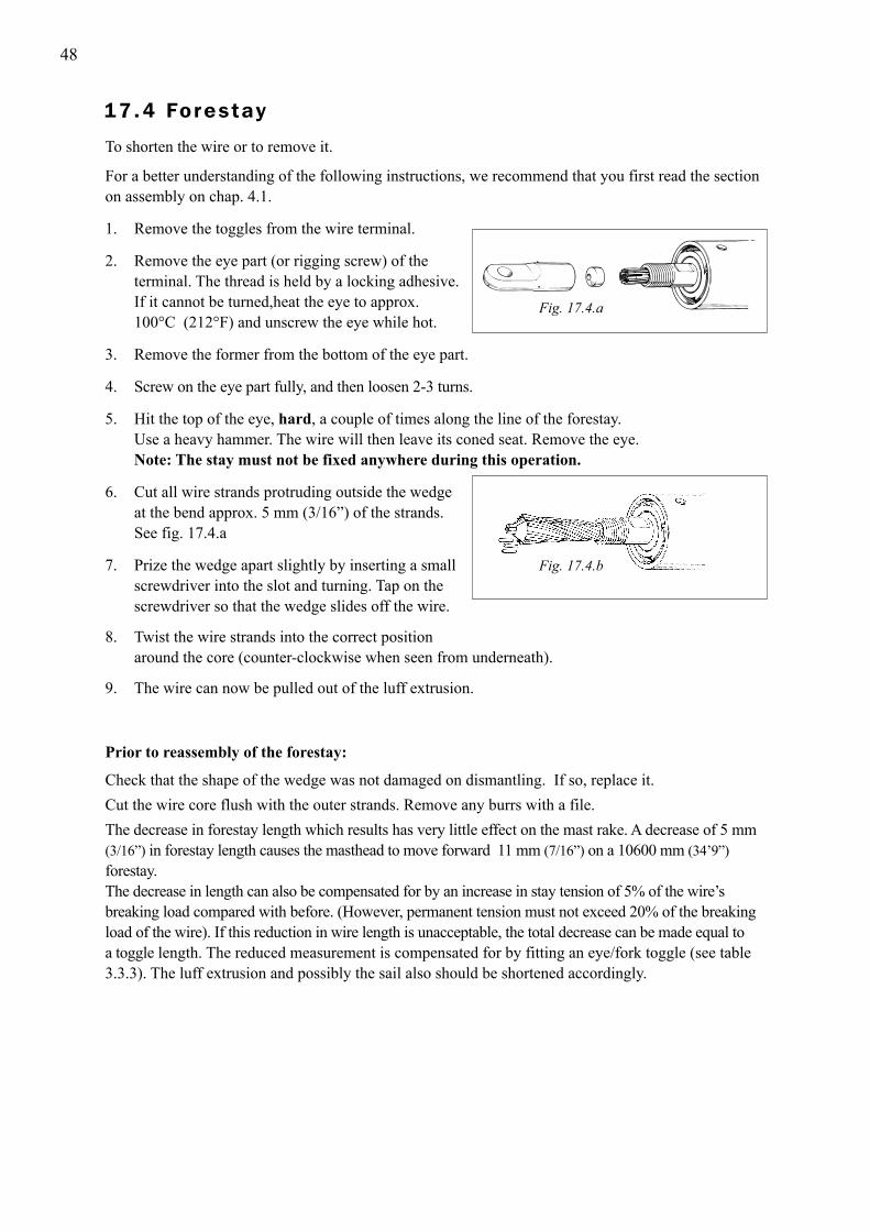
2. Remove the eye part (or rigging screw) of the terminal. The thread is held by a locking adhesive. If it cannot be turned,heat the eye to approx. 100°C (212°F) and unscrew the eye while hot.
3. Remove the former from the bottom of the eye part.
4. Screw on the eye part fully, and then loosen 2-3 turns.
5. Hit the top of the eye, hard, a couple of times along the line of the forestay. Use a heavy hammer. The wire will then leave its coned seat. Remove the eye. Note: The stay must not be fixed anywhere during this operation.
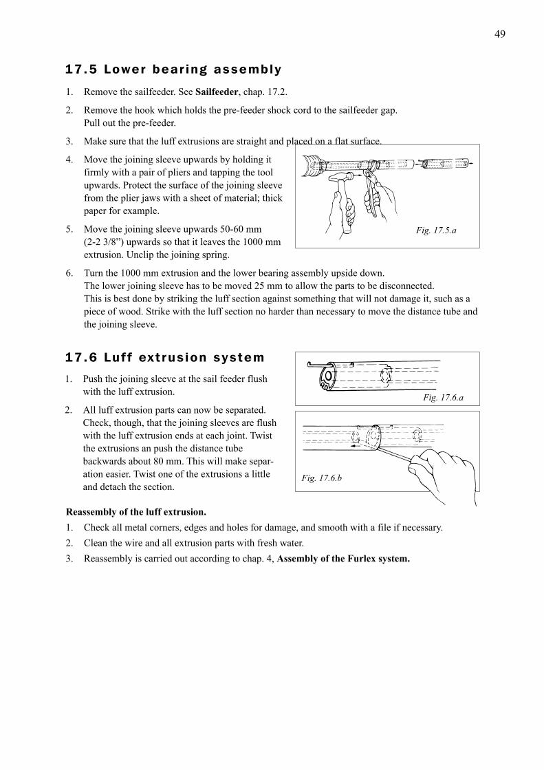
6. Cut all wire strands protruding outside the wedge at the bend approx. 5 mm (3/16”) of the strands. See fig. 17.4.a
7. Prize the wedge apart slightly by inserting a small screwdriver into the slot and turning. Tap on the screwdriver so that the wedge slides off the wire.
8. Twist the wire strands into the correct position around the core (counter-clockwise when seen from underneath).
9. The wire can now be pulled out of the luff extrusion.
Fig. 17.4.a
Fig. 17.4.b
Prior to reassembly of the forestay:
Check that the shape of the wedge was not damaged on dismantling. If so, replace it.Cut the wire core flush with the outer strands. Remove any burrs with a file.The decrease in forestay length which results has very little effect on the mast rake. A decrease of 5 mm (3/16”) in forestay length causes the masthead to move forward 11 mm (7/16”) on a 10600 mm (34’9”) forestay.The decrease in length can also be compensated for by an increase in stay tension of 5% of the wire’s breaking load compared with before. (However, permanent tension must not exceed 20% of the breaking load of the wire). If this reduction in wire length is unacceptable, the total decrease can be made equal to a toggle length. The reduced measurement is compensated for by fitting an eye/fork toggle (see table 3.3.3). The luff extrusion and possibly the sail also should be shortened accordingly.
17.4 Forestay
49
1. Remove the sailfeeder. See Sailfeeder, chap. 17.2.
2. Remove the hook which holds the pre-feeder shock cord to the sailfeeder gap. Pull out the pre-feeder.
3. Make sure that the luff extrusions are straight and placed on a flat surface.
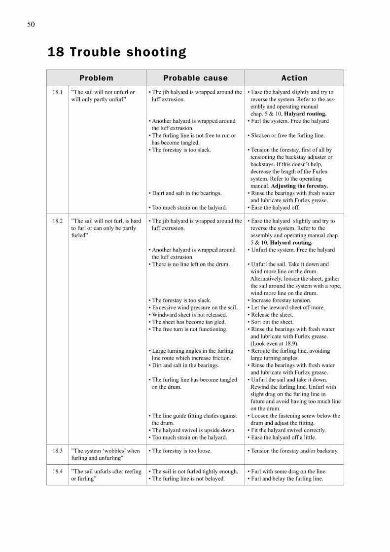
4. Move the joining sleeve upwards by holding it firmly with a pair of pliers and tapping the tool upwards. Protect the surface of the joining sleeve from the plier jaws with a sheet of material; thick paper for example.
5. Move the joining sleeve upwards 50-60 mm (2-2 3/8”) upwards so that it leaves the 1000 mm extrusion. Unclip the joining spring.
6. Turn the 1000 mm extrusion and the lower bearing assembly upside down. The lower joining sleeve has to be moved 25 mm to allow the parts to be disconnected. This is best done by striking the luff section against something that will not damage it, such as a piece of wood. Strike with the luff section no harder than necessary to move the distance tube and the joining sleeve.
Fig. 17.5.a
Fig. 17.6.a
Fig. 17.6.b
Reassembly of the luff extrusion.1. Check all metal corners, edges and holes for damage, and smooth with a file if necessary.2. Clean the wire and all extrusion parts with fresh water.3. Reassembly is carried out according to chap. 4, Assembly of the Furlex system.
17.5 Lower bear ing assembly
17.6 Luf f ext rus ion system
1. Push the joining sleeve at the sail feeder flush with the luff extrusion.
2. All luff extrusion parts can now be separated. Check, though, that the joining sleeves are flush with the luff extrusion ends at each joint. Twist the extrusions an push the distance tube backwards about 80 mm. This will make separ- ation easier. Twist one of the extrusions a little and detach the section.
50
18 Trouble shooting
Problem Probable cause Action
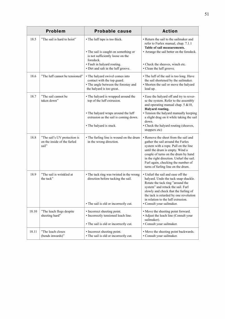
18.1 ”The sail will not unfurl or will only partly unfurl”
• The jib halyard is wrapped around the luff extrusion.
• Another halyard is wrapped around the luff extrusion.• The furling line is not free to run or has become tangled.• The forestay is too slack.
• Dairt and salt in the bearings.
• Too much strain on the halyard.
• Ease the halyard slightly and try to reverse the system. Refer to the ass- embly and operating manual chap. 5 & 10, Halyard routing.• Furl the system. Free the halyard
• Slacken or free the furling line. • Tension the forestay, first of all by tensioning the backstay adjuster or backstays. If this doesn’t help, decrease the length of the Furlex system. Refer to the operating manual. Adjusting the forestay.• Rinse the bearings with fresh water and lubricate with Furlex grease. • Ease the halyard off.
18.2 ”The sail will not furl, is hard to furl or can only be partly furled”
• The jib halyard is wrapped around the luff extrusion.
• Another halyard is wrapped around the luff extrusion.• There is no line left on the drum.
• The forestay is too slack.• Excessive wind pressure on the sail.• Windward sheet is not released.• The sheet has become tan gled.• The free turn is not functioning.
• Large turning angles in the furling line route which increase friction.• Dirt and salt in the bearings.
• The furling line has become tangled on the drum.
• The line guide fitting chafes against the drum.• The halyard swivel is upside down.• Too much strain on the halyard.
• Ease the halyard slightly and try to reverse the system. Refer to the assembly and operating manual chap. 5 & 10, Halyard routing.• Unfurl the system. Free the halyard
• Unfurl the sail. Take it down and wind more line on the drum. Alternatively, loosen the sheet, gather the sail around the system with a rope, wind more line on the drum.• Increase forestay tension.• Let the leeward sheet off more.• Release the sheet.• Sort out the sheet.• Rinse the bearings with fresh water and lubricate with Furlex grease. (Look even at 18.9).• Reroute the furling line, avoiding large turning angles.• Rinse the bearings with fresh water and lubricate with Furlex grease.• Unfurl the sail and take it down. Rewind the furling line. Unfurl with slight drag on the furling line in future and avoid having too much line on the drum.• Loosen the fastening screw below the drum and adjust the fitting.• Fit the halyard swivel correctly.• Ease the halyard off a little.
18.3 ”The system ‘wobbles’ when furling and unfurling”
• The forestay is too loose. • Tension the forestay and/or backstay.
18.4 ”The sail unfurls after reefing or furling”
• The sail is not furled tightly enough.• The furling line is not belayed.
• Furl with some drag on the line.• Furl and belay the furling line.
51
Problem Probable cause Action
18.5 ”The sail is hard to hoist” • The luff tape is too thick.
• The sail is caught on something or is not sufficiently loose on the foredeck.• Fault in halyard routing.• Dirt and salt in the luff groove.
• Return the sail to the sailmaker and refer to Furlex manual, chap. 7.1.1 Table of sail measurements.• Arrange the sail better on the foredeck.
• Check the sheaves, winch etc.• Clean the luff groove.
18.6 ”The luff cannot be tensioned” • The halyard swivel comes into contact with the top guard.• The angle between the forestay and the halyard is too great.
• The luff of the sail is too long. Have the sail shortened by the sailmaker.• Shorten the sail or move the halyard lead up.
18.7 ”The sail cannot be taken down”
• The halyard is wrapped around the top of the luff extrusion.
• The halyard wraps around the luff extrusion as the sail is coming down.
• The halyard is stuck.
• Ease the halyard off and try to rever- se the system. Refer to the assembly and operating manual chap. 5 &10, Halyard routing.• Tension the halyard manually keeping a slight drag on it while taking the sail down.• Check the halyard routing (sheaves, stoppers etc)
18.8 ”The sail’s UV protection is on the inside of the furled sail”
• The furling line is wound on the drum in the wrong direction.
• Remove the sheet from the sail and gather the sail around the Furlex system with a rope. Pull on the line until the drum is empty. Wind a couple of turns on the drum by hand in the right direction. Unfurl the sail. Furl again, checking the number of turns of furling line on the drum.
18.9 ”The sail is wrinkled at the tack”
• The tack ring was twisted in the wrong direction before tacking the sail.
• The sail is old or incorrectly cut.
• Unfurl the sail and ease off the halyard. Undo the tack snap shackle. Rotate the tack ring ”around the system” and retack the sail. Furl slowly and check that the furling of the tack is retarded by one revolution in relation to the luff extrusion.• Consult your sailmaker.
18.10 ”The leach flogs despite sheeting hard”
• Incorrect sheeting point.• Incorrectly tensioned leach line.
• The sail is old or incorrectly cut.
• Move the sheeting point forward.• Adjust the leach line (Consult your sailmaker).• Consult your sailmaker.
18.11 ”The leach closes(bends inwards)”
• Incorrect sheeting point.• The sail is old or incorrectly cut.
• Move the sheeting point backwards.• Consult your sailmaker.

We are sure that your Furlex will give you many years of enjoyment and wish you
and your crew happy sailing.
www.seldenmast.com
Sweden: Seldén Mast AB • Tel: +46 (0)31 69 69 00 • [email protected] Denmark: Seldén Mast A/S • Tel: +45 39 18 44 00 • [email protected]: Seldén Mast Ltd. • Tel: +44 (0)1329 50 40 00 • [email protected] the Nether lands: Seldén Mid Europe B.V. • Tel: +31 (0)111- 698 120 • [email protected] USA: Seldén Mast Inc. • Tel: +1 843-760-6278 • [email protected] France: Seldén Mast SAS • Tel: 33 (0) 251 362 110 • [email protected]
595-
9102
-E
Pri
nted
in S
wed
en
S
eldé
n an
d F
urle
x ar
e re
gist
ered
trad
emar
ks o
f S
eldé
n M
ast A
B
Go through the checklist below and make sure that all the important instructions have been carriedout. This will ensure that the Furlex system functions safely and reliably under all conditions.
19 Checklist
19.1 Points to check before sailingSee
chapter
� Check that the angle between the halyard and forestay is 5 - 10° when the sail is hoisted.
5
� Check that the clearance between the halyard swivel and the top guard is not less than 20 mm.
7.1
� Do all the sails used have the maximum luff length or an extension pendant? 7.1
� Check that no halyard can get caught in the halyard swivel or wrapped around the luff extrusion.
5.3
� Check that the line guide eye does not deflect the furling line too much, as this can cause extra friction and wear.
6.3
� Check that the free turn is functioning, i.e. the tack swivel is turned in the right direction. Some load on the sheet should cause the luff section to rotate one revolution before the tack rotates.
12.1
� Check that the line guide fitting does not contact the line drum flanges. 4.3
� Check that the Furlex stay articulates freely at the upper and lower attachment. 3.1
� Check that all the split pins are secured. 3.3