Embed Size (px)
Citation preview
Ohio EPA
State of Ohio Environmental Protection Agency
Manual of Ohio EPA Surveillance Methods
and Quality Assurance Practices
2009
Division of Surface Water
Division of Environmental Services
DSW Field Manual
Ohio EPA, Division of Surface Water Page 1 of 2
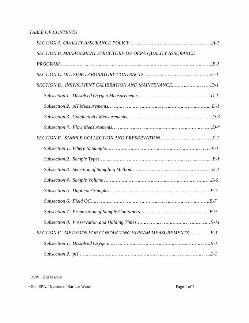
TABLE OF CONTENTS
SECTION A. QUALITY ASSURANCE POLICY ……………………………………………..….A-1
SECTION B. MANAGEMENT STRUCTURE OF OEPA QUALITY ASSURANCE
PROGRAM ……………………………………………………………………………………….…..B-1
SECTION C. OUTSIDE LABORATORY CONTRACTS ……………………………………….C-1
SECTION D. INSTRUMENT CALIBRATION AND MAINTENANCE………………………D-1
Subsection 1. Dissolved Oxygen Measurements…………………………………………. D-1
Subsection 2. pH Measurements……………………………………………………………...D-1
Subsection 3. Conductivity Measurements…………………………………………………..D-3
Subsection 4. Flow Measurements……………………………………………………………D-4
SECTION E. SAMPLE COLLECTION AND PRESERVATION………………………………E-1
Subsection 1. Where to Sample…………………………………………………………… …E-1
Subsection 2. Sample Types……………………………………………………………………E-1
Subsection 3. Selection of Sampling Method………………………………………………..E-2
Subsection 4. Sample Volume ………………………………………………………………..E-6
Subsection 5. Duplicate Samples…………………………………………………………….E-7
Subsection 6. Field QC……………………………………………………………………….E-7
Subsection 7. Preparation of Sample Containers…………………………………………E-9
Subsection 8. Preservation and Holding Times……………………………………………E-11
SECTION F. METHODS FOR CONDUCTING STREAM MEASUREMENTS……………E-1
Subsection 1. Dissolved Oxygen……………………………………………………………..E-1
Subsection 2. pH……………………………………………………………………………….E-1
DSW Field Manual
Ohio EPA, Division of Surface Water Page 2 of 2
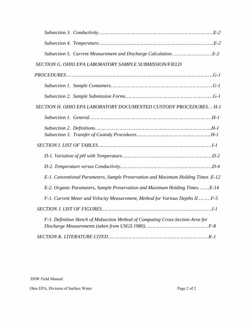
Subsection 3. Conductivity…………………………………………………………………….E-2
Subsection 4. Temperature…………………………………………………………………….E-2
Subsection 5. Current Measurement and Discharge Calculation……………………….E-2
SECTION G. OHIO EPA LABORATORY SAMPLE SUBMISSION/FIELD
PROCEDURES………………………………………………………………………………………..G-1
Subsection 1. Sample Containers…………………………………………………………….G-1
Subsection 2. Sample Submission Forms……………………………………………………G-1
SECTION H. OHIO EPA LABORATORY DOCUMENTED CUSTODY PROCEDURES… H-1
Subsection 1. General…………………………………………………………………………H-1
Subsection 2. Definitions……………………………………………………………………..H-1 Subsection 3. Transfer of Custody Procedures……………………………………………H-1
SECTION I. LIST OF TABLES……………………………………………………………………I-1
D-1. Variation of pH with Temperature……………………………………………………..D-2
D-2. Temperature versus Conductivity………………………………………………………D-4
E-1. Conventional Parameters, Sample Preservation and Maximum Holding Times .E-12
E-2. Organic Parameters, Sample Preservation and Maximum Holding Times……..E-14
F-1. Current Meter and Velocity Measurement, Method for Various Depths II………F-5
SECTION J. LIST OF FIGURES…………………………………………………………………J-1
F-1. Definition Sketch of Midsection Method of Computing Cross-Section Area for Discharge Measurements (taken from USGS 1980)………………….………………….F-8
SECTION K. LITERATURE CITED……………………………………………………………K-1
DSW Field Manual
Ohio EPA, Division of Surface Water Page 1 of 1
DISCLAIMER:
The mention of trade names or commercial products in this manual does not constitute endorsement or recommendation for use by the Ohio Environmental Protection Agency.
INTRODUCTION
In response to the need for an overall program to coordinate the collection and reporting of water quality monitoring data, and to ensure the reliability of such data, the Ohio Environmental Protection Agency (Ohio EPA), Division of Environmental Services (DES) and Division of Surface Water (DSW) have developed this Manual of Ohio EPA Surveillance Methods & Quality Assurance Practices. This manual includes a statement of the Ohio EPA quality assurance policy, as well as a description of the management structure of the quality assurance program. Laboratory elements to be used in support of the various monitoring activities are defined.
Quality assurance procedures for field operations, laboratory methods, data reporting, and chain of custody are defined. Included are minimum quality assurance requirements for contracts between Ohio EPA and outside laboratories.
Manual of Ohio EPA Surveillance Methods Document Revision: 0 And Quality Assurance Practices Section: Quality Assurance Policy Date: January 2, 2009
DSW Field Manual
Ohio EPA, Division of Surface Water Page 1 of 1
SECTION A. QUALITY ASSURANCE POLICY
The general objective of this manual is to promote greater standardization of procedures for all facets of sample collection, data generation, and reporting used in support of Ohio EPA's efforts in water pollution control and abatement. Therefore, the methods and quality assurance practices defined in this manual shall be used by all Ohio EPA personnel when collecting data.
Specific objectives of this manual are to establish detailed and documented procedures for the collection and reporting of all water quality data and to define criteria for the acceptance or rejection of data generated by these methods. Where applicable, control limits on the precision and accuracy of these methods will be established and only data that falls within these limits will be reported without qualification. To achieve these goals, Ohio EPA will commit a minimum of 10% of its monitoring and assessment program to quality assurance activities.
Laboratory Quality Control Policy. Ten percent of the samples collected will be analyzed in duplicate to establish levels of precision. Ten percent of the samples will be spiked and analyzed for recovery efficiency and accuracy. Control limits based on precision and accuracy will determine the acceptance or rejection of laboratory data on a daily basis. Quality control samples obtained from sources external to the laboratory will be analyzed daily. These samples are used to check laboratory performance. Quarterly intra-laboratory audits are also conducted during which unknown proficiency testing samples are analyzed for a majority of the parameters that are tested.
Field Quality Control Policy. Ten percent of the samples collected will be used for quality control purposes. Duplicate samples will be used to determine representativeness of sampling. Field samples may be split for inter-laboratory comparisons. Field blanks consisting of distilled deionized water and preservative, where appropriate, will be submitted along with regular samples to establish practicable detection limits and to monitor for levels of contaminants to which field samples may be exposed. All field instruments used in the measurement of physical, chemical, or biological parameters shall be properly calibrated and maintained. Records will be kept of these operations for each instrument.
Inter-laboratory Quality Control Policy. The Division of Environmental Services (DES) participates in several national inter-laboratory proficiency testing (PT) studies annually. These PT studies are administered by USEPA contractors and PT providers accredited by the National Institute of Standards and Technology (NIST). Participation in the studies satisfies some of the quality assurance requirements for the wastewater, drinking water and air pollution monitoring programs. Participation is on a biannual basis for the wastewater and drinking water programs and quarterly for the air program.
Manual of Ohio EPA Surveillance Methods Document Revision: 0 And Quality Assurance Practices Section: Management Structure of Ohio EPA Quality Assurance Program Date: January 2, 2009
DSW Field Manual
Ohio EPA, Division of Surface Water Page 1 of 1
SECTION B. MANAGEMENT STRUCTURE OF OEPA QUALITY ASSURANCE PROGRAM
Responsibility for the Ohio EPA surface water and effluent monitoring programs are divided among several semi-independent work sections. Field operations are conducted by various Ohio EPA District and Central Office personnel. The Division of Environmental Services is responsible for analyses of samples collected for routine monitoring programs and ambient and compliance monitoring, as well as intensive and TMDL water quality surveys. Ohio EPA Surface Water staffs collect samples for in-stream biological monitoring programs and laboratory bioassays. Fecal coliform, E. coli, and fecal strep analyses are performed at the DES laboratory as well as at contract laboratories in some of the districts.
DES quality assurance staff will review and update the Manual of Laboratory Standard Operating Procedures, Volumes I, II and III, and the Quality Assurance Plan at the end of each year. The Quality Assurance Plan defines performance standards for all aspects of data collection activities. Laboratory quality control and method detection limits (MDLs) are updated annually or more frequently as is deemed appropriate. Reporting limits (RLs) are assessed annually to ensure programmatic data quality objectives are being met.
The Division of Surface Water is in the process of identifying numerical Data Quality Objectives (DQO) and data submission expectations. The Division will initiate a rule making to address this issue. Meeting surface water quality standards and permit limits are our objectives, and these limits will help determine our DQOs.
Manual of Ohio EPA Surveillance Methods Document Revision: 0 And Quality Assurance Practices Section: Outside Laboratory Contracts Policy Date: January 2, 2009
DSW Field Manual
Ohio EPA, Division of Surface Water Page 1 of 1
SECTION C. OUTSIDE LABORATORY CONTRACTS POLICY
Whenever Ohio EPA negotiates an analytical services contract with a laboratory independent of direct Ohio EPA control, the DES Quality Assurance Officer (QAO) will be responsible for:
1) Ensuring that the laboratory has adequate facilities and staff to perform the analytical services,
2) Requiring the laboratory to use only analytical procedures set forth in 40 CFR 136 - "Test Procedures for the Analysis of Pollutants" (or Approved Alternative Test Procedures), and
3) Requiring that the laboratory demonstrate its analytical expertise by participating in PT studies administered by NIST accredited providers. PT samples must be analyzed for all parameters covered in the contract and performance evaluation reports must be made available to the QAO.
4) In addition, the QAO will outline the minimum day-to-day quality control program that the laboratory must carry out in order to document the validity of its analytical data.
Manual of Ohio EPA Surveillance Methods Document Revision: 0 And Quality Assurance Practices Section: Instrument Calibration and Maintenance Date: January 2, 2009
DSW Field Manual
Ohio EPA, Division of Surface Water Page 1 of 5
SECTION D. INSTRUMENT CALIBRATION AND MAINTENANCE
Each Ohio EPA monitoring crew will be required to maintain a separate, up-to-date calibration and maintenance logbook for each piece of equipment. The logbook must be hardbound with consecutively numbered pages. The make, model, serial and/or ID number of each meter must be entered in the logbook. The appropriate calibration procedure must be followed and the results must be recorded in the logbook each time a piece of field equipment is used, along with the date and name/initials of the person performing the calibration. If difficulty is encountered in calibrating an instrument, or if the instrument will not hold calibration, this information must also be recorded. Malfunctioning equipment should not be used to collect data. Proper steps should be taken to correct the problem as soon as possible. All equipment maintenance should be recorded in the logbook indicating what was done to correct the problem along with the date and signature of the staff person that corrected the problem.
Subsection 1. Dissolved Oxygen Measurement.
Maintain and operate the meter in accordance with the manufacturer's instructions. Record all calibration, use, and repair and maintenance information in the logbook including name/initials and date.
Subsection 2. pH Measurement
Part a) Maintain and operate the meter in accordance with the manufacturer's instructions. Record all calibration, use, and repair and maintenance information in the logbook, including name/initials and date.
Part b) At the start of each sampling day, calibrate using two reference buffers, (7 and either 4 or 10 depending upon the expected pH of the samples to be run). If the expected reading is alkaline, use pH 7 and pH 10 buffers. If the expected reading is acidic, use pH 7 and pH 4 buffers. The value of the sample should register within 2 pH units of the selected buffers.
Part c) Buffer solutions should not be used if past expiration date. Date all buffer bottles with the expiration date when new buffer solutions are received. Rotate stock as appropriate.
NOTE: The response of a pH electrode is temperature dependent. If a temperature compensating pH probe is not used, the instrument should be calibrated under field conditions. It may be necessary to store buffers in insulated containers to prevent them
Manual of Ohio EPA Surveillance Methods Document Revision: 0 And Quality Assurance Practices Section: Instrument Calibration and Maintenance Date: January 2, 2009
DSW Field Manual
Ohio EPA, Division of Surface Water Page 2 of 5
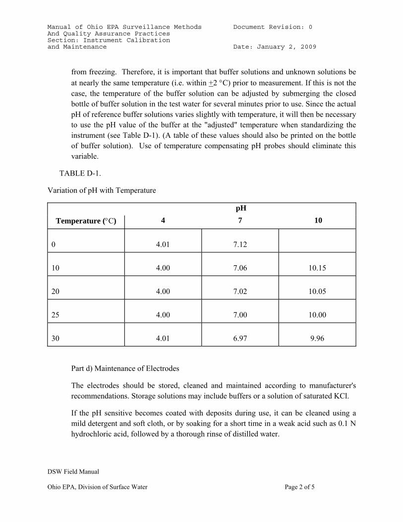
from freezing. Therefore, it is important that buffer solutions and unknown solutions be at nearly the same temperature (i.e. within +2 °C) prior to measurement. If this is not the case, the temperature of the buffer solution can be adjusted by submerging the closed bottle of buffer solution in the test water for several minutes prior to use. Since the actual pH of reference buffer solutions varies slightly with temperature, it will then be necessary to use the pH value of the buffer at the "adjusted" temperature when standardizing the instrument (see Table D-1). (A table of these values should also be printed on the bottle of buffer solution). Use of temperature compensating pH probes should eliminate this variable.
TABLE D-1.
Variation of pH with Temperature
pH Temperature (°C) 4 7 10
0
4.01 7.12
10
4.00 7.06 10.15
20
4.00 7.02 10.05
25
4.00 7.00 10.00
30
4.01 6.97 9.96
Part d) Maintenance of Electrodes
The electrodes should be stored, cleaned and maintained according to manufacturer's recommendations. Storage solutions may include buffers or a solution of saturated KCl.
If the pH sensitive becomes coated with deposits during use, it can be cleaned using a mild detergent and soft cloth, or by soaking for a short time in a weak acid such as 0.1 N hydrochloric acid, followed by a thorough rinse of distilled water.
Manual of Ohio EPA Surveillance Methods Document Revision: 0 And Quality Assurance Practices Section: Instrument Calibration and Maintenance Date: January 2, 2009
DSW Field Manual
Ohio EPA, Division of Surface Water Page 3 of 5
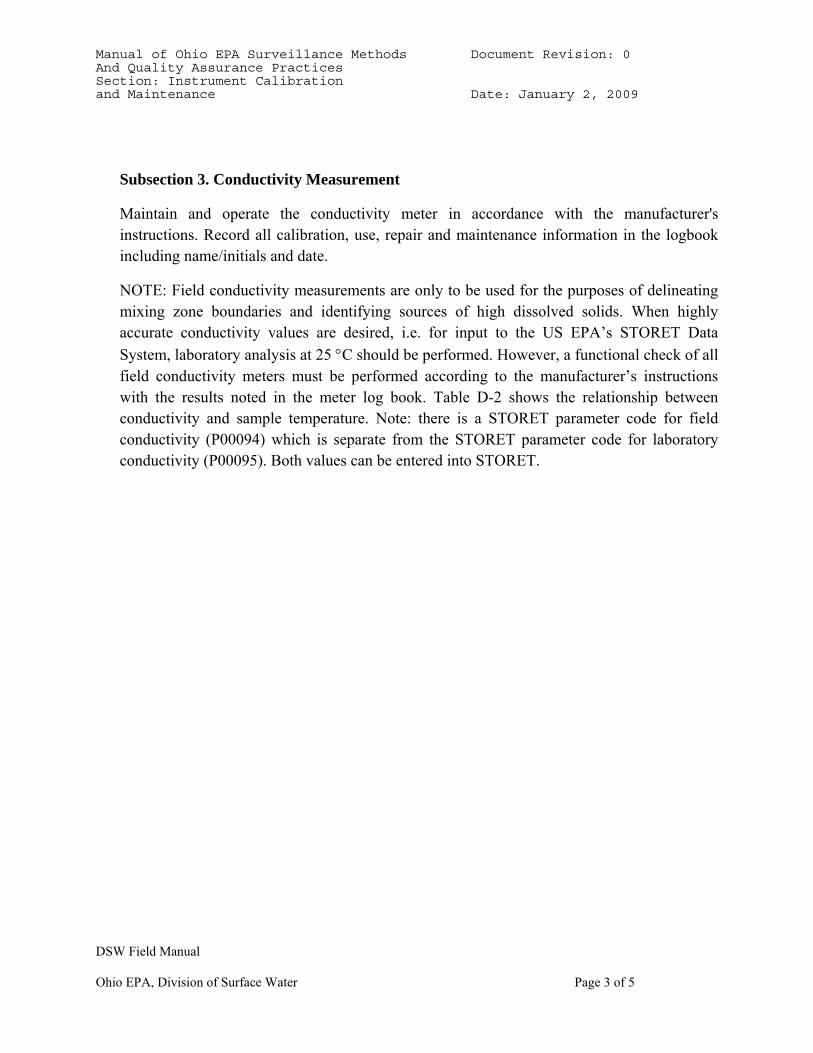
Subsection 3. Conductivity Measurement
Maintain and operate the conductivity meter in accordance with the manufacturer's instructions. Record all calibration, use, repair and maintenance information in the logbook including name/initials and date.
NOTE: Field conductivity measurements are only to be used for the purposes of delineating mixing zone boundaries and identifying sources of high dissolved solids. When highly accurate conductivity values are desired, i.e. for input to the US EPA’s STORET Data System, laboratory analysis at 25 °C should be performed. However, a functional check of all field conductivity meters must be performed according to the manufacturer’s instructions with the results noted in the meter log book. Table D-2 shows the relationship between conductivity and sample temperature. Note: there is a STORET parameter code for field conductivity (P00094) which is separate from the STORET parameter code for laboratory conductivity (P00095). Both values can be entered into STORET.
Manual of Ohio EPA Surveillance Methods Document Revision: 0 And Quality Assurance Practices Section: Instrument Calibration and Maintenance Date: January 2, 2009
DSW Field Manual
Ohio EPA, Division of Surface Water Page 4 of 5
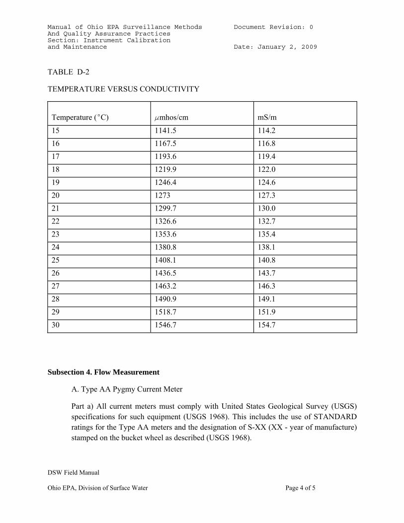
TABLE D-2
TEMPERATURE VERSUS CONDUCTIVITY
Temperature (EC)
Fmhos/cm mS/m
15 1141.5 114.2 16 1167.5 116.8 17 1193.6 119.4 18 1219.9 122.0 19 1246.4 124.6 20 1273 127.3 21 1299.7 130.0 22 1326.6 132.7 23 1353.6 135.4 24 1380.8 138.1 25 1408.1 140.8 26 1436.5 143.7 27 1463.2 146.3 28 1490.9 149.1 29 1518.7 151.9 30 1546.7 154.7
Subsection 4. Flow Measurement
A. Type AA Pygmy Current Meter
Part a) All current meters must comply with United States Geological Survey (USGS) specifications for such equipment (USGS 1968). This includes the use of STANDARD ratings for the Type AA meters and the designation of S-XX (XX - year of manufacture) stamped on the bucket wheel as described (USGS 1968).
Manual of Ohio EPA Surveillance Methods Document Revision: 0 And Quality Assurance Practices Section: Instrument Calibration and Maintenance Date: January 2, 2009
DSW Field Manual
Ohio EPA, Division of Surface Water Page 5 of 5
Part b) Up-to-date, accurate rating tables are available or can be established for all Type - AA meters.
Part c) If up-to-date, accurate rating tables are not available for the Pygmy current meters, they should be submitted to USGS for laboratory ratings as required. These meters cannot be used until such tables are available.
Part d) USGS guidelines (USGS 1968) will apply to the care and maintenance of all flow meters, including the following specific requirements:
1) A spin test must be performed before and after each use of Type AA, or Pygmy meter. The Type AA meter must spin for a minimum of 1.5 minutes and the Pygmy meter must spin for a minimum of 30 seconds. Record the spin times in the logbook or on the flow sheet. If the meter fails the initial spin test, it should be repaired before use. If it fails the final spin test, a note should be made on the data report sheet. If possible, the problem should be corrected and the measurement repeated.
2) Clean, oil, and store current meters according to USGS guidelines following each day's use (USGS 1968).
B. SonTek FlowTracker Flow Meter
Calibrate and operate the flow meter according to manufacturer’s instructions. Consult the SonTek Operation Manual for detailed operation and maintenance information. All velocimeters should be updated with the latest software and firmware available. About once per week (or prior to each field trip) perform a BeamCheck diagnostic test to verify FlowTracker performance.
An automated field QC check should be performed at least once/day (or preferably every time a flow is measured). The results are automatically stored with each discharge measurement. This test does not replace the office BeamCheck.
Manual of Ohio EPA Surveillance Methods Document Revision: 0 And Quality Assurance Practices Section: Sample Collection and Preservation Date: January 2, 2009
DSW Field Manual
Ohio EPA, Division of Surface Water Page 1 of 14
SECTION E. SAMPLE COLLECTION AND PRESERVATION
"The most precise and accurate analytical measurements are worthless and even detrimental if performed on a sample that was improperly collected and stored, or was contaminated in the process. The purpose of sampling and analysis is to provide data which can be used to interpret the quality or condition of the water under investigation. For this reason, the sampling and testing program should be established in accordance with principles which will permit valid interpretation. Unfortunately, water quality characteristics are not spatially or temporally uniform from one effluent to another. A sampling program must recognize such variations and provide a basis for compensations for their effects. The sample must be: (a) representative of the material being examined; (b) uncontaminated by the sampling technique or container; (c) of adequate size for all laboratory examinations; (d) properly and completely identified; (e) properly preserved, and (f) delivered and analyzed within established holding times. These six requirements are absolutely necessary for a proper water or wastewater survey. Additional aspects are discussed below" (OEPA 1978).
Note: appropriate personal protective equipment (PPE) such as gloves and safety glasses should be worn when collecting samples. PPE use should be based on known risks (CSO areas, unsewered areas, downstream from WWTP discharges, cuts on your hands, etc.). It is recommended that gloves be worn when collecting bacteria and CSI/toxics/bioassay samples. Use best professional judgment. If you are not sure, wear gloves.
Subsection 1. Where to Sample
It is impossible to establish hard and fast rules concerning sampling locations. However, the following general guidelines should be applied:
Part a) The sampling location should be selected based upon the specific information to be obtained.
Part b) If possible, the sampling location should be where the stream and effluent is well mixed. Natural turbulence can be used to provide a good mixture.
Part c) Samples should be collected at a location where the velocity is sufficient to prevent deposition of solids.
Subsection 2. Sample Types
Part a) Grab Sample - "A grab sample is defined as an individual sample collected over a period of time not exceeding 15 minutes. Grab samples represent only the condition that
Manual of Ohio EPA Surveillance Methods Document Revision: 0 And Quality Assurance Practices Section: Sample Collection and Preservation Date: January 2, 2009
DSW Field Manual
Ohio EPA, Division of Surface Water Page 2 of 14
exists at the time the wastewater is collected" (USEPA 1977).
1) Surface Grab Sample - the sample is collected at the water surface directly into the sample container or into an intermediate container such as a clean bucket.
2) Subsurface Grab Sample - the sample is collected at a specific depth in the water column. A Kemmerer or VanDorn water sampler (Welch 1948) may be used.
3) Integrated Grab Sample - defined as a "...mixture of grab samples collected from different points simultaneously, or as nearly so as possible...". An example of the need for such sampling occurs in a river or stream that varies in composition across its width and depth" (APHA 16th Edition 1985). Samples should be collected from several horizontal locations across the stream section. Vertical integration is accomplished by allowing the sampling container to fill continuously as it is dropped down through the water column and as it is pulled to the surface from the bottom.
Part b) Composite Sample - A composite sample should contain discrete samples taken at equal time intervals over the compositing period, or proportional to the flow rate over the compositing period (USEPA 1977). All composite samples should be identified as to the method of sampling collection, duration of composite (e.g. 24 hours), and frequency of the sampling (e.g. every 2 hours).
Subsection 3. Selection of Sampling Method
Part a) Grab Samples are appropriate for the characterization of a stream at a particular time, to provide information about minimum and maximum concentrations, to allow for the collection of variable sample volume, to comply with the NPDES Permit monitoring specifications, or to corroborate with a composite sample. When in the field, double rinse the sampling device (bucket, automatic sampler) with sample water prior to collecting the sample. For inorganic samples, a pre-rinse of the sample container is acceptable but not required. Do not pre-rinse sample containers for bacteria samples, organic samples and oil and grease.
NOTE: Grab samples are also used for the collection of some special types of samples as described in part c) Parameters that Require Specia1 Collection Techniques.
1) Surface grab samples are to be used for stream sampling when collecting floating materials, such as oil and grease. Surface grab samples should be collected from enough horizontal locations to characterize the shore-to-shore distribution of the parameter(s) of interest.
Manual of Ohio EPA Surveillance Methods Document Revision: 0 And Quality Assurance Practices Section: Sample Collection and Preservation Date: January 2, 2009
DSW Field Manual
Ohio EPA, Division of Surface Water Page 3 of 14
2) Subsurface grab samples may be appropriate when collecting a water sample to determine water quality at various discrete depths.
3) Integrated grab samples are to be used to collect stream grab samples when incomplete mixing exists. Conductivity measurements and visual observations can be utilized to determine if horizontal plumes and/or vertical stratification are present.
Part b) Composite samples are required when a widely variable flow, or parameter concentration, is being sampled and "average" concentrations, or loadings, are desired. Twenty-four hour composite samples are to be used in NPDES Compliance Monitoring
Sampling Inspections (except as noted in Part c below) to test compliance with "daily average" concentration limits in NPDES Permits. Twenty-four hour composite samples shall also be used to determine if any effluent toxicity exists, when collecting effluent samples for bioassays.
Part c) Parameters requiring special collection techniques:
1) Organics - Do not pre-rinse sample containers. All samples must be iced or refrigerated at less than or equal to 6 °C from the time of collection until analysis. Samples requiring analysis for purgeables-Volatile Organic Compounds (VOCs) must be collected as a GRAB sample in two- 40 ml glass vials with teflon-lined septum sealed caps. The sample vial must be filled to overflowing in such a manner that no air bubbles pass through the sample as the vial is being filled. If 2 drops of 1:1 HCl preservative have been added, the vial should be shaken vigorously for 1 minute. The addition of preservative extends the holding time from 7 to 14 days. The hermetic seal on the sample vial must be maintained until the time of analysis.
Samples requiring analysis of acid/base/neutral extractables (BNAs) should be collected in two, non-preserved, amber glass quart jars. The caps of sample containers must be teflon-lined. All samples must be iced or refrigerated at less than or equal to 6°C.
Samples for polychlorinated biphenyls (PCBs) and pesticide analyses require the collection of 2 additional, non-preserved, amber glass quart jars with teflon-lined caps. All samples must be iced or refrigerated at less than or equal to 6°C.
Samples analyzed for the organic compounds Alachlor, Atrazine, Metolachlor, Simazine, Metribuzin and the agricultural herbicide Cyanazine, using Ohio EPA
Manual of Ohio EPA Surveillance Methods Document Revision: 0 And Quality Assurance Practices Section: Sample Collection and Preservation Date: January 2, 2009
DSW Field Manual
Ohio EPA, Division of Surface Water Page 4 of 14
Method 525.2 require two, non-preserved glass amber jars and two glass amber jars preserved in the field with 40-50 mg of sodium sulfite to reduce residual chlorine then 6 N HCl to adjust the pH to<2. The non-preserved samples are only required for Cyanazine, as it degrades in acidic conditions.
All samples must be iced or refrigerated at less than or equal to 6°C.
Samples analyzed for CARBAMATE pesticides (Aldicarb, Aldicarb Sulfone, Aldicarb Sulfoxide, Carbaryl, Carbofuran, 3-Hydroxycarbofuran, Methiocarb, Methomyl, Oxamyl, Propoxur) using Ohio EPA Method 531.1 require two- 40 ml glass vials with teflon-lined septum sealed caps. Do not pre-rinse the vials. Add 4 mg of sodium thiosulfate per 40 ml of sample if chlorine is present or suspected. Fill vials approximately 1/2 to 3/4 full, add 1.2 ml of monochloroacetic acid buffer then top with additional sample (meniscus is not necessary). Shake vial vigorously to mix preservatives. All samples must be iced or refrigerated at less than or equal to 6°C.
Samples analyzed for GLYPHOSATE herbicides (Glialka, Roundup, Sting, Rodeo, Spasor, Muster, Tumbleweed, Sonic, Glifonox, Glycel, Rondo) using Ohio EPA Method 547 require two- 40 ml glass vials with teflon-lined septum sealed caps. Add 4 mg of sodium thiosulfate per 40 ml of sample if chlorine is present or suspected. Leave no headspace in the vial. All samples must be iced or refrigerated at less than or equal to 6°C. Keep samples away from light until analysis.
a) Automatic sampling equipment must be as free as possible of Tygon tubing and other potential sources of contamination. Teflon or teflon lined Tygon tubing is acceptable for use as organic sampling intake line. PVC/Tygon tubing is acceptable for use as conventional sampling intake line. The pump tubing can be organic chemical resistant Tygon peristaltic pump tubing or silicone tubing supplied by the manufacturer.
b) VOC samples containing residual chlorine must be treated with sodium thiosulfate. Use a spatula to add 3 mg of sodium thiosulfate per 40 ml of sample.
2) Oil & Grease - The only acceptable method for collecting oil and grease samples is to collect the sample DIRECTLY into a one quart, laboratory issued, glass jar. A teflon-lined lid must be used.
3) Cyanide - Samples requiring analysis of cyanide should be collected in quart
Manual of Ohio EPA Surveillance Methods Document Revision: 0 And Quality Assurance Practices Section: Sample Collection and Preservation Date: January 2, 2009
DSW Field Manual
Ohio EPA, Division of Surface Water Page 5 of 14
cubitainers and preserved with 6-10 pellets (depending on size) of sodium hydroxide (NaOH) transferred to the container without handling the preservative. The pH of the sample must be > 12 S.U. Verify the sample pH is within the desirable range before departing from the sampling site. Cyanide samples must be collected as GRAB samples.
4) Phenols - Samples requiring analysis of phenols must be collected in glass, laboratory issued, containers. A white polypropylene cap with a foam polyethylene liner must be used. Black and green caps contain phenol and must be avoided. Also avoid caps with cardboard liners. Phenols must be collected as grab samples.
Phenols for compliance monitoring require the collection of additional sample to meet the volume requirements of manual distillation. Sample volumes exceeding 125 ml should be collected in one liter glass container(s) with white polypropylene cap(s) with a foam polyethylene liner. Two ml of H2SO4 should be added per liter of sample as a preservative.
5) pH/Acidity/Alkalinity - Samples for the analysis of these parameters should not be composited when sampling NPDES Permit discharges whose effluent has a highly variable pH that might be expected to exceed the permit limits during a given 24 hour period. Note: pH must be collected as a GRAB sample.
6) Dissolved Parameters - Samples should be collected as grab samples, membrane filtered immediately using a 0.45 micron filter, and chemically preserved (if appropriate). See Table E-1 for preservatives. Note on cubitainer and the sample submission form that the sample has been filtered. Separate data sheets must be submitted for filtered samples.
7) Bacteria - Samples are to be collected directly into a sterilized, glass or polypropylene (or other autoclavable plastic) bottle. Samples should be collected by hand according to the following procedure:
The collection container should be submerged into the water carefully to avoid contamination from land and surface debris. This is accomplished by holding the container near the base with one hand and removing the cap with the other hand. The container is quickly pushed into the water to a depth of about six inches with the mouth of the collection container down. The mouth of the bottle is then tilted
Manual of Ohio EPA Surveillance Methods Document Revision: 0 And Quality Assurance Practices Section: Sample Collection and Preservation Date: January 2, 2009
DSW Field Manual
Ohio EPA, Division of Surface Water Page 6 of 14
upward into the current and is allowed to fill. If there is no current, move the container through the water in a continuous and unbroken movement. Bottles should be filled to between 2/3 and 3/4 full. Add sodium thiosulfate crystals or 0.1 ml of a 10 % sodium thiosulfate solution to the sample if residual chlorine is suspected.
For safety reasons, it may be impossible to collect a bacteria sample directly into the sterile container. If samples must be collected remotely, a clean bucket may be used to collect the sample and then the sampled transferred to the sterile container. An alternative method is to attach the sterile sample container to a string and lower into the stream. The collection method should eliminate any possibility of contamination of the sample. The sterile container should be filled to between 2/3 and 3/4 full.
Bacteria samples collected to document unsanitary conditions in water bodies that are not listed in the water quality standards rules should follow procedures in the Water Quality Standards Guidance #3, Sampling Methods for Documentation of a Public Health Nuisance Under OAC 3745-1-04 (F) & (G) (Ohio EPA 1998). This guidance document is available at: www.epa.state.oh.us/dsw/guidance/wqs3.pdf
8) Metals - Serious errors may be introduced during sampling due to contamination from a metal sampling device and the failure to remove residues of previous samples from the sample container. To eliminate such errors, ensure that the sampling device and all materials coming into contact with the sample are glass or polyethylene plastic and have been properly cleaned (non-phosphorus detergent wash, tap water rinse, distilled water rinse) prior to sampling.
Subsection 4. Sample Volume
The size of the final sample is an important consideration. This must be more than required for all the tests to be made, thus providing for any duplicate or repeat examinations that may be necessary. In general, this should be from 1 to 2 liters in volume, but will depend upon the number of parameters to be analyzed.
NOTE: Some analytical methods require that the entire sample be used so that separate samples are required for these tests (see Tables E-1 and E-2 for details).
Manual of Ohio EPA Surveillance Methods Document Revision: 0 And Quality Assurance Practices Section: Sample Collection and Preservation Date: January 2, 2009
DSW Field Manual
Ohio EPA, Division of Surface Water Page 7 of 14
Subsection 5. Duplicate Samples
The ability to collect reproducible samples of stream water, or wastewater, for subsequent laboratory analysis is dependent upon factors such as: the method of sample collection, the specific parameters to be analyzed, and the characteristics of the particular water being sampled.
In order to develop criteria for acceptable sample variations in physical and/or chemical composition resulting from sampling procedures, the above factors affecting the laboratory analysis of the sample(s) must be controlled. The results of these analyses will be used by the QAO to develop parameter-specific precision limits in accordance with the procedures outlined in USEPA 1977; USEPA 1972; and Youden 1973.
NOTE: If field filtration is required, those samples should be filtered in duplicate and submitted for laboratory analysis.
For inorganic parameters, oil and grease, volatile, semi-volatile, pesticides, PCBs, and herbicides, label one set of containers and complimentary lab sheet as ”DUPLICATE A“ and the other set as ”DUPLICATE B“. Duplicate samples should be submitted at a frequency of 10% of the total number of samples.
Trip blanks are used to document contamination attributable to shipping and field handling procedures. They should remain in the cooler at the sampling site.
Subsection 6. Field QC: Field Blanks/VOC Trip Blanks/ Equipment Blanks /Matrix Spike Duplicates/Acid Blanks
Part a) Field Blank- Procedure for Conventional and Organic Parameters (Acid/Base/Neutral Extractables (BNAs), Herbicides, Pesticides and PCBs): field blanks for conventional and organic parameter analysis must be prepared in the field to evaluate the potential for contamination of a sample by site contaminants from a source not associated with the sample collected (i.e. air-borne dust, etc.). Distilled deionized water (i.e. Nanopure) is taken into the field in a sealed container. The distilled deionized water is then poured into the sample container and the appropriate chemical preservative is added. The containers and sample submission forms are labeled as “FIELD BLANK“. The same template selected for the test samples should be used. Field blanks are subject to the same holding time limitations as samples. The appropriate FIELD QC box on the sample
Manual of Ohio EPA Surveillance Methods Document Revision: 0 And Quality Assurance Practices Section: Sample Collection and Preservation Date: January 2, 2009
DSW Field Manual
Ohio EPA, Division of Surface Water Page 8 of 14
submission form should be checked. Field blanks should be submitted at a frequency of 5%.
Note: the distilled deionized water (Nanopure) obtained from DES is acceptable for use for conventional parameter, BNA, pesticide, and PCB blanks, provided a fresh supply (stored less than 28 days in the carboy) of the distilled deionized water is available and it is stored in clean storage containers.
Part b) Trip Blank- Trip blanks are used to determine if samples were contaminated during storage and/or transportation back to the laboratory. A trip blank is only required for volatile organic compound sampling. A trip blank is prepared for field personnel by the laboratory staff prior to the sampling event and is stored in the same cooler with the investigative VOC samples throughout the sampling event. At no time after their preparation are trip blanks to be opened before they reach the laboratory. To obtain trip blanks, please contact the laboratory and inform them of the number needed. Trip blank VOC containers and sample submission forms are labeled ” TRIP BLANK “. Trip blanks should be kept on ice in the cooler, along with the VOC samples during the entire sampling run. They must be stored in an iced cooler from the time of collection, while they are in the sampling vehicle, until they arrive at the laboratory. One VOC trip blank per cooler should be submitted. VOC trip blanks must be analyzed within 14 days from the date they are taken into the field. Trip blanks prepared more than 30 days prior to the sampling event should be discarded and not taken into the field.
Part c) Equipment Blank- Equipment blanks are collected after the completion of decontamination of sampling equipment and prior to sampling. An equipment blank must be prepared by running distilled deionized water through the sampling equipment and adding the appropriate chemical preservative in order to check for the contamination of samples by the containers or the preservatives and to establish "practicable" detection limits. Equipment blanks can be prepared in the field or in the laboratory. One equipment blank must be prepared for each type of preservative used. Label the containers and lab sheet ”EQUIPMENT BLANK “. Mark the appropriate FIELD QC box on the sample submission form. Use the same parameter template as the test samples. Equipment blanks should be submitted at a frequency of 5%.
Part d) Matrix Spike Duplicates- matrix spike samples should be submitted at a frequency of 5%. For oil and grease use three jars. For VOC volatiles use four glass vials. For semi-volatiles, pesticides, PCBs, or herbicides use four amber,
Manual of Ohio EPA Surveillance Methods Document Revision: 0 And Quality Assurance Practices Section: Sample Collection and Preservation Date: January 2, 2009
DSW Field Manual
Ohio EPA, Division of Surface Water Page 9 of 14
glass laboratory issued jars. Eight jars are needed if both PCB and BNA samples are submitted. On the lab sheet, write ”MATRIX SPIKE“ across the top. Mark the appropriate FIELD QC box on the sample submission form.
Part e) Acid Blank- Acid blanks must be submitted whenever the acid dispensers have been cleaned or maintained or when a new lot of acid ampules have been received. Samples must be prepared by filling a sample container with distilled deionized water and adding the appropriate chemical preservative. Mark the appropriate FIELD QC box on the sample submission form.
Subsection 7. Preparation of Sample Containers
Part a) Quart and gallon size disposable, soft, polyethylene cubitainers with disposable polypropylene lids should be used as sample containers for all samples not requiring special containers (see Tables E-1 and E-2).
Containers must be stored with lids on until sample is collected. Prepare and submit cubitainer blank QA/QC samples as directed by DES. When cubitainer blanks are submitted to DES, enter the lot number from the box containing the cubitainers onto the lab sheet.
Part b) Oil & Grease
1) Only one quart glass jars with teflon-lined screw caps should be used as sample containers for this parameter. No intermediate container is allowed for sampling this parameter.
2) Jars must be stored with the lids ON until the sample is collected.
Part c) Organics
1) Quart amber glass jars with teflon-lined screw caps should be used as sample containers.
2) Glass jars must be stored with the lids ON until the sample is collected.
3) Volatile organic parameters must be collected in 40 ml glass vials with septum seals.
Manual of Ohio EPA Surveillance Methods Document Revision: 0 And Quality Assurance Practices Section: Sample Collection and Preservation Date: January 2, 2009
DSW Field Manual
Ohio EPA, Division of Surface Water Page 10 of 14
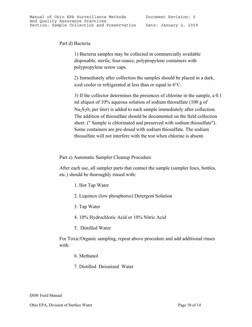
Part d) Bacteria
1) Bacteria samples may be collected in commercially available disposable, sterile, four-ounce, polypropylene containers with polypropylene screw caps.
2) Immediately after collection the samples should be placed in a dark, iced cooler or refrigerated at less than or equal to 6°C.
3) If the collector determines the presences of chlorine in the sample, a 0.1 ml aliquot of 10% aqueous solution of sodium thiosulfate (100 g of Na2S203 per liter) is added to each sample immediately after collection. The addition of thiosulfate should be documented on the field collection sheet. (" Sample is chlorinated and preserved with sodium thiosulfate"). Some containers are pre-dosed with sodium thiosulfate. The sodium thiosulfate will not interfere with the test when chlorine is absent.
Part e) Automatic Sampler Cleanup Procedure
After each use, all sampler parts that contact the sample (sampler lines, bottles, etc.) should be thoroughly rinsed with:
1. Hot Tap Water
2. Liquinox (low phosphorus) Detergent Solution
3. Tap Water
4. 10% Hydrochloric Acid or 10% Nitric Acid
5. Distilled Water
For Toxic/Organic sampling, repeat above procedure and add additional rinses with:
6. Methanol
7. Distilled Deionized Water
Manual of Ohio EPA Surveillance Methods Document Revision: 0 And Quality Assurance Practices Section: Sample Collection and Preservation Date: January 2, 2009
DSW Field Manual
Ohio EPA, Division of Surface Water Page 11 of 14
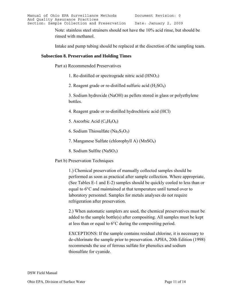
Note: stainless steel strainers should not have the 10% acid rinse, but should be rinsed with methanol.
Intake and pump tubing should be replaced at the discretion of the sampling team.
Subsection 8. Preservation and Holding Times
Part a) Recommended Preservatives
1. Re-distilled or spectrograde nitric acid (HNO3)
2. Reagent grade or re-distilled sulfuric acid (H2SO4)
3. Sodium hydroxide (NaOH) as pellets stored in glass or polyethylene bottles.
4. Reagent grade or re-distilled hydrochloric acid (HCl)
5. Ascorbic Acid (C6H8O6)
6. Sodium Thiosulfate (Na2S2O3)
7. Manganese Sulfate (chlorophyll A) (MnSO4)
8. Sodium Sulfite (NaSO3)
Part b) Preservation Techniques
1.) Chemical preservation of manually collected samples should be performed as soon as practical after sample collection. Where appropriate, (See Tables E-1 and E-2) samples should be quickly cooled to less than or equal to 6°C and maintained at that temperature until turned over to laboratory personnel. Samples for metals analyses do not require refrigeration after preservation.
2.) When automatic samplers are used, the chemical preservatives must be added to the sample bottle(s) after compositing. All samples must be kept at less than or equal to 6°C during the compositing period.
EXCEPTIONS: If the sample contains residual chlorine, it is necessary to de-chlorinate the sample prior to preservation. APHA, 20th Edition (1998) recommends the use of ferrous sulfate for phenolics and sodium thiosulfate for cyanide.
Manual of Ohio EPA Surveillance Methods Document Revision: 0 And Quality Assurance Practices Section: Sample Collection and Preservation Date: January 2, 2009
DSW Field Manual
Ohio EPA, Division of Surface Water Page 12 of 14
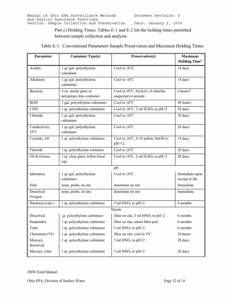
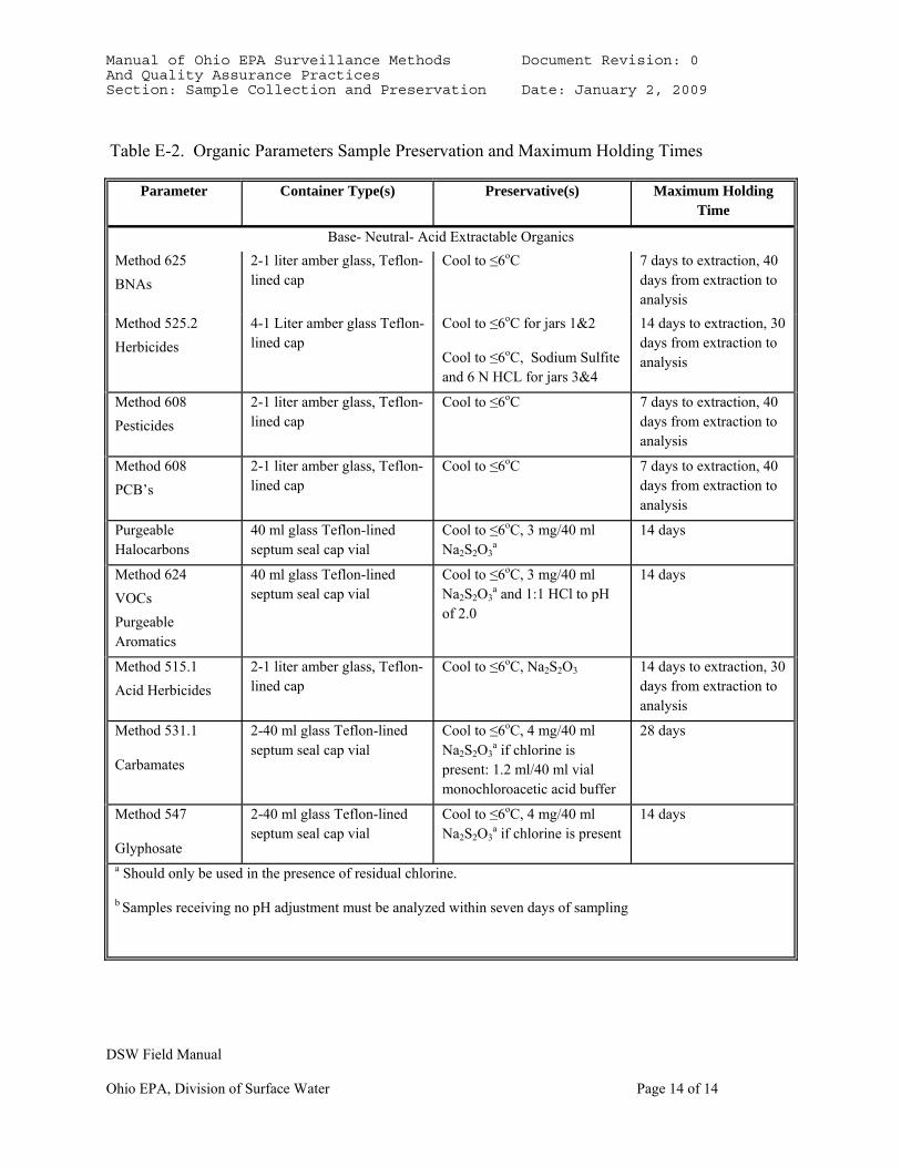
Part c) Holding Times: Tables E-1 and E-2 list the holding times permitted between sample collection and analysis.
Table E-1. Conventional Parameters Sample Preservation and Maximum Holding Times
Parameter Container Type(s) Preservative(s) Maximum Holding Timea
Acidity 1 qt./gal. polyethylene cubitainer
Cool to ≤6°C 14 days
Alkalinity 1 qt./gal. polyethylene cubitainer
Cool to ≤6oC 14 days
Bacteria 4 oz. sterile glass or polypropy-lene container
Cool to 10oC, Na2S2O3 if chlorine suspected or present
6 hours*
BOD 1 gal. polyethylene cubitainer Cool to ≤6oC 48 hours
COD 1 qt. polyethylene cubitainer Cool to ≤6oC, 2 ml H2SO4 to pH<2 28 days
Chloride 1 qt./gal. polyethylene cubitainer
Cool to ≤6oC 28 days
Conductivity, 25oC
1 qt./gal. polyethylene cubitainer
Cool to ≤6oC 28 days
Cyanide, All 1 qt. polyethylene cubitainer Cool to ≤6oC, 6-10 pellets NaOH to pH>12
14 days
Fluoride 1 qt. polyethylene container Cool to ≤6oC 28 days
Oil & Grease 1 qt. clear glass, teflon-lined cap
Cool to ≤6oC, 2 ml H2SO4 to pH<2 28 days
pH laboratory 1 qt./gal. polyethylene
cubitainer Cool to ≤6oC Immediate upon
receipt at lab field none, probe, in-situ determine on site Immediate
Dissolved Oxygen
none, probe, in-situ determine on site Immediate
Hardness (calc.) 1 qt. polyethylene cubitainer 5 ml HNO3 to pH<2 6 months
Metals Dissolved qt. polyethylene cubitainer filter on site, 5 ml HNO3 to pH<2 6 months Suspended 1 qt. polyethylene cubitainer filter on site, retain filter pad 6 months Total 1 qt. polyethylene cubitainer 5 ml HNO3 to pH<2 6 months Chromium (VI) 1 qt. polyethylene cubitainer filter on site, cool to 4oC 24 hours Mercury, dissolved
1 qt. polyethylene cubitainer 5 ml HNO3 to pH<2 28 days
Mercury, total 1 qt. polyethylene cubitainer 5 ml HNO3 to pH<2 28 days
Manual of Ohio EPA Surveillance Methods Document Revision: 0 And Quality Assurance Practices Section: Sample Collection and Preservation Date: January 2, 2009
DSW Field Manual
Ohio EPA, Division of Surface Water Page 13 of 14
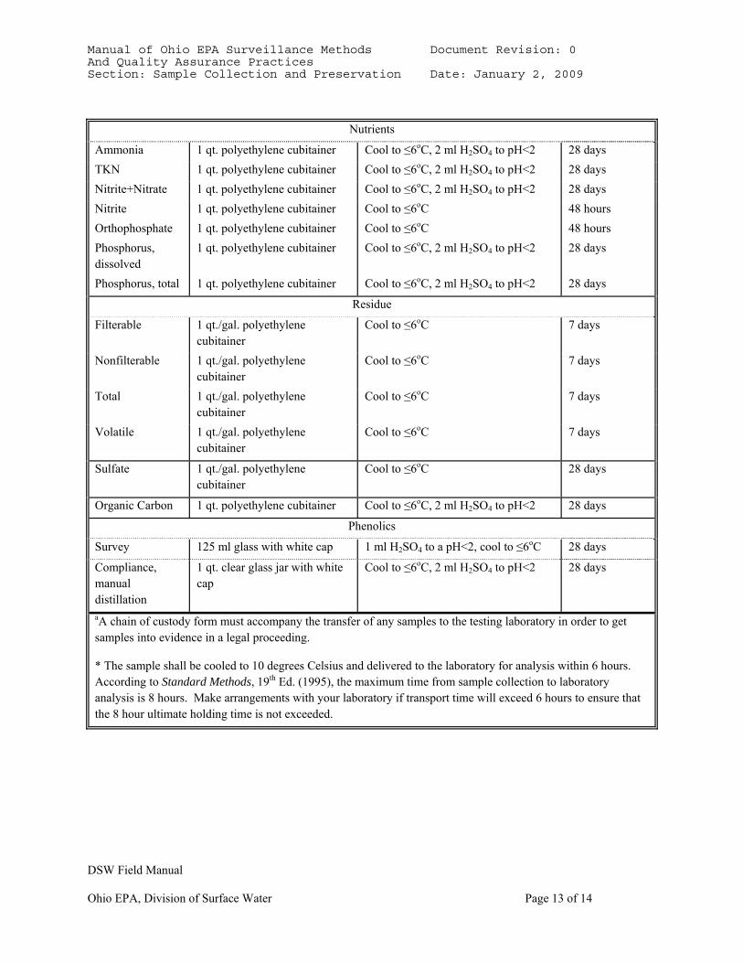
Nutrients
Ammonia 1 qt. polyethylene cubitainer Cool to ≤6oC, 2 ml H2SO4 to pH<2 28 days TKN 1 qt. polyethylene cubitainer Cool to ≤6oC, 2 ml H2SO4 to pH<2 28 days Nitrite+Nitrate 1 qt. polyethylene cubitainer Cool to ≤6oC, 2 ml H2SO4 to pH<2 28 days Nitrite Orthophosphate
1 qt. polyethylene cubitainer 1 qt. polyethylene cubitainer
Cool to ≤6oC Cool to ≤6oC
48 hours 48 hours
Phosphorus, dissolved
1 qt. polyethylene cubitainer Cool to ≤6oC, 2 ml H2SO4 to pH<2 28 days
Phosphorus, total 1 qt. polyethylene cubitainer Cool to ≤6oC, 2 ml H2SO4 to pH<2 28 days
Residue
Filterable 1 qt./gal. polyethylene cubitainer
Cool to ≤6oC 7 days
Nonfilterable 1 qt./gal. polyethylene cubitainer
Cool to ≤6oC 7 days
Total 1 qt./gal. polyethylene cubitainer
Cool to ≤6oC 7 days
Volatile 1 qt./gal. polyethylene cubitainer
Cool to ≤6oC 7 days
Sulfate 1 qt./gal. polyethylene cubitainer
Cool to ≤6oC 28 days
Organic Carbon 1 qt. polyethylene cubitainer Cool to ≤6oC, 2 ml H2SO4 to pH<2 28 days
Phenolics
Survey 125 ml glass with white cap 1 ml H2SO4 to a pH<2, cool to ≤6oC 28 days
Compliance, manual distillation
1 qt. clear glass jar with white cap
Cool to ≤6oC, 2 ml H2SO4 to pH<2 28 days
aA chain of custody form must accompany the transfer of any samples to the testing laboratory in order to get samples into evidence in a legal proceeding.
* The sample shall be cooled to 10 degrees Celsius and delivered to the laboratory for analysis within 6 hours. According to Standard Methods, 19th Ed. (1995), the maximum time from sample collection to laboratory analysis is 8 hours. Make arrangements with your laboratory if transport time will exceed 6 hours to ensure that the 8 hour ultimate holding time is not exceeded.
Manual of Ohio EPA Surveillance Methods Document Revision: 0 And Quality Assurance Practices Section: Sample Collection and Preservation Date: January 2, 2009
DSW Field Manual
Ohio EPA, Division of Surface Water Page 14 of 14
Table E-2. Organic Parameters Sample Preservation and Maximum Holding Times
Parameter Container Type(s) Preservative(s) Maximum Holding Time
Base- Neutral- Acid Extractable Organics Method 625 BNAs
2-1 liter amber glass, Teflon-lined cap
Cool to ≤6oC 7 days to extraction, 40 days from extraction to analysis
Method 525.2 Herbicides
4-1 Liter amber glass Teflon-lined cap
Cool to ≤6oC for jars 1&2
Cool to ≤6oC, Sodium Sulfite and 6 N HCL for jars 3&4
14 days to extraction, 30 days from extraction to analysis
Method 608 Pesticides
2-1 liter amber glass, Teflon-lined cap
Cool to ≤6oC 7 days to extraction, 40 days from extraction to analysis
Method 608 PCB’s
2-1 liter amber glass, Teflon-lined cap
Cool to ≤6oC 7 days to extraction, 40 days from extraction to analysis
Purgeable Halocarbons
40 ml glass Teflon-lined septum seal cap vial
Cool to ≤6oC, 3 mg/40 ml Na2S2O3
a 14 days
Method 624 VOCs Purgeable Aromatics
40 ml glass Teflon-lined septum seal cap vial
Cool to ≤6oC, 3 mg/40 ml Na2S2O3
a and 1:1 HCl to pH of 2.0
14 days
Method 515.1 Acid Herbicides
2-1 liter amber glass, Teflon-lined cap
Cool to ≤6oC, Na2S2O3 14 days to extraction, 30 days from extraction to analysis
Method 531.1
Carbamates
2-40 ml glass Teflon-lined septum seal cap vial
Cool to ≤6oC, 4 mg/40 ml Na2S2O3
a if chlorine is present: 1.2 ml/40 ml vial monochloroacetic acid buffer
28 days
Method 547
Glyphosate
2-40 ml glass Teflon-lined septum seal cap vial
Cool to ≤6oC, 4 mg/40 ml Na2S2O3
a if chlorine is present 14 days
a Should only be used in the presence of residual chlorine.
b Samples receiving no pH adjustment must be analyzed within seven days of sampling
Manual of Ohio EPA Surveillance Methods Document Revision: 0 And Quality Assurance Practices Section: Methods for Conducting Stream Measurements Date: January 2, 2009
DSW Field Manual
Ohio EPA, Division of Surface Water Page 1 of 8
SECTION F. METHODS FOR CONDUCTING STREAM MEASUREMENTS
Subsection 1. Dissolved Oxygen (D.O.)
Part a) General
1) Measurement of D.O. shall be performed using a dissolved oxygen meter. Values should be reported to the nearest 0.1 mg/1 unless calibrated to 0.01 mg/l.
2) It is important that a minimum water velocity of one foot per second be maintained across the surface of the D.O. probe. If the probe is used in slow-moving water, jiggling the probe cable will provide the needed agitation. However, some meters use a rapid pulse oxygen sensor that does not require stirring.
3) A temperature measurement should accompany each D.O. measurement (see Section D, Subsection 4). Readings should be recorded to the nearest 0.1 °C.
4) Dissolved oxygen measurements should be taken at enough locations across the stream section and through the vertical water column to characterize the variation in D.O. concentration at a given site. Use best professional judgment.
5) Dissolved oxygen measurements may be collected from bridges by using a dissolved oxygen meter equipped with the appropriate probe cable.
Subsection 2. pH
Part a) General
1) The pH meter must be standardized as described in Section B.
2) The sample should be stirred for several seconds by gently moving the pH electrode back and forth through the sample prior to measurement. This will minimize the time needed for the equilibration of the electrode.
3) An integrated grab sample (see Section C, Subsection 2, Part a-3), should be used to represent the "average" pH of the stream at any given time.
Manual of Ohio EPA Surveillance Methods Document Revision: 0 And Quality Assurance Practices Section: Methods for Conducting Stream Measurements Date: January 2, 2009
DSW Field Manual
Ohio EPA, Division of Surface Water Page 2 of 8
Subsection 3. Conductivity
The conductivity meter should be checked as described in Section B. Report conductivity values in umhos/cm. A temperature measurement should accompany each conductivity measurement (see Section D, Subsection 4). Conductivity measurements can be made in-situ, or remotely using a meter equipped with the appropriate length cable.
Specific conductance can only be reported from laboratory measurements. Field conductivity measurement results can be reported as long as the appropriate STORET code is used.
Subsection 4. Temperature
Thermistors on D.O. and conductivity meters, or thermometers, can be used to measure water temperature. All field temperature measuring devices (thermistors and field thermometers) must be standardized monthly against a non-mercury NBS calibrated thermometer. Report temperature values to the nearest 0.1 °C.
Subsection 5. Current Measurement and Discharge Calculation
The accuracy of a wastewater measurement system varies widely, depending principally upon the primary flow devices used. The total error inherent in a flow measuring system is, of course, the sum of each component part of the system. However, any system that cannot measure the wastewater flow within +10% is considered unacceptable for NPDES Permit compliance purposes.
1. Flow Meters The following procedures typically used for mechanical (Pygmy and AA) flow meters also apply to the use of the FlowTracker:
a.) The measurement section should be within a straight stream reach, where streamlines are parallel. The streambed should be relatively uniform and free of numerous boulders, debris, and heavy aquatic growth. The flow should be relatively uniform and free of eddies, slack water, and excessive turbulence. The ideal section is perpendicular to the direction of the flow, with uniform bed and banks, a minimum velocity greater than 0.5 fps, and a depth adequate for use of the two-point method.
b.) After selecting the reach, determine the width of the stream by stringing a tag line or measuring tape at right angles to the direction of flow.
Manual of Ohio EPA Surveillance Methods Document Revision: 0 And Quality Assurance Practices Section: Methods for Conducting Stream Measurements Date: January 2, 2009
DSW Field Manual
Ohio EPA, Division of Surface Water Page 3 of 8
c.) Determine the spacing of the verticals.
1) Generally, use about 25 to 30 partial sections. (When there are smooth cross-sections and a good velocity distribution, fewer sections may be used).
2) Space the sections so that any one section has no more than 10% (ideally 5%) of the total flow passing through it.
3) Equal widths of partial sections are not recommended unless the discharge is well distributed. (Make the section width less, as depths and velocities become greater.)
d.)Velocity sample time: under normal measurement conditions, each point velocity measurement should be sampled for a minimum of 40 seconds. Under extreme flow conditions, such as rapidly changing stage, a shorter sample time may be used to lessen the time needed to complete the discharge measurement. e.)Location of velocity observations in each vertical: at depths of 1.5 feet or less, the 0.6-depth method should be used; at depths between 1.5 and 2.5 feet, the 2 point (0.2/0.8) method should be used unless the 0.8 depth measurement is located less than 2 inches from a rock or other boundary. At depths greater than 2.5 feet, the two-point method should be used. f.)A flow data sheet should be completed every time a stream discharge measurement is made, specifying stream name, river mile, specific site description, latitude/longitude (including the method used, e.g. GPS), date and time, staff names, weather conditions, stream bottom description, the type of meter suspended and the meter’s serial number, and, if using the SonTek unit, the flowtracker data file name. Record the time the measurement began and ended. Record which bank of the stream that was the starting point (LEW or REW, i.e., left edge of water or right edge of water, when facing downstream). Record the duration of the current meter spin test, before and after measurement if using the Pygmy or AA meter.
g.) Flowtracker flow data: All flow measurement data files should be saved. Recommended format for file name: Filename.nnn, where “Filename” is an 8 digit stream and site ID. The “nnn” suffix serves to identify the date, with the first digit used for the month, and the other 2 digits for the day. The year can’t be specified in filename.nnn, so it s important to fill a field sheet with additional details for each filename used. See examples below:
Manual of Ohio EPA Surveillance Methods Document Revision: 0 And Quality Assurance Practices Section: Methods for Conducting Stream Measurements Date: January 2, 2009
DSW Field Manual
Ohio EPA, Division of Surface Water Page 4 of 8
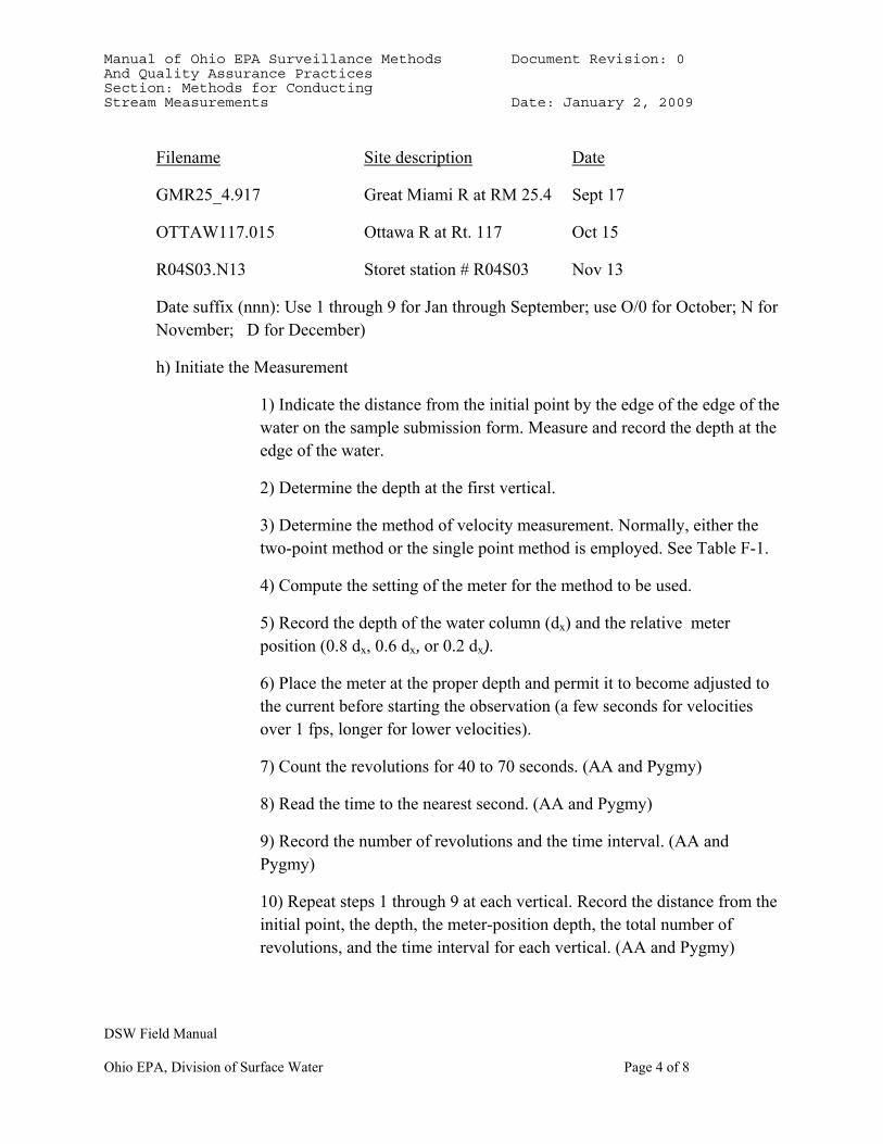
Filename Site description Date
GMR25_4.917 Great Miami R at RM 25.4 Sept 17
OTTAW117.015 Ottawa R at Rt. 117 Oct 15
R04S03.N13 Storet station # R04S03 Nov 13
Date suffix (nnn): Use 1 through 9 for Jan through September; use O/0 for October; N for November; D for December)
h) Initiate the Measurement
1) Indicate the distance from the initial point by the edge of the edge of the water on the sample submission form. Measure and record the depth at the edge of the water.
2) Determine the depth at the first vertical.
3) Determine the method of velocity measurement. Normally, either the two-point method or the single point method is employed. See Table F-1.
4) Compute the setting of the meter for the method to be used.
5) Record the depth of the water column (dx) and the relative meter position (0.8 dx, 0.6 dx, or 0.2 dx).
6) Place the meter at the proper depth and permit it to become adjusted to the current before starting the observation (a few seconds for velocities over 1 fps, longer for lower velocities).
7) Count the revolutions for 40 to 70 seconds. (AA and Pygmy)
8) Read the time to the nearest second. (AA and Pygmy)
9) Record the number of revolutions and the time interval. (AA and Pygmy)
10) Repeat steps 1 through 9 at each vertical. Record the distance from the initial point, the depth, the meter-position depth, the total number of revolutions, and the time interval for each vertical. (AA and Pygmy)
Manual of Ohio EPA Surveillance Methods Document Revision: 0 And Quality Assurance Practices Section: Methods for Conducting Stream Measurements Date: January 2, 2009
DSW Field Manual
Ohio EPA, Division of Surface Water Page 5 of 8
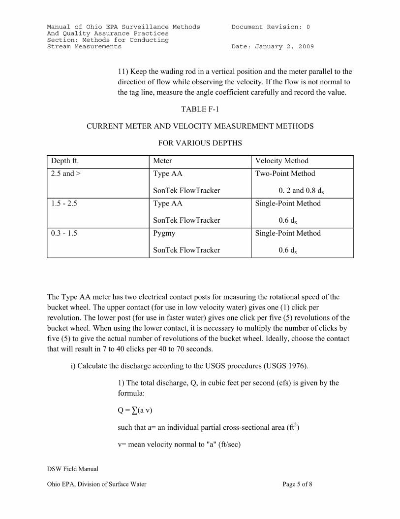
11) Keep the wading rod in a vertical position and the meter parallel to the direction of flow while observing the velocity. If the flow is not normal to the tag line, measure the angle coefficient carefully and record the value.
TABLE F-1
CURRENT METER AND VELOCITY MEASUREMENT METHODS
FOR VARIOUS DEPTHS
Depth ft. Meter Velocity Method 2.5 and > Type AA
SonTek FlowTracker
Two-Point Method
0. 2 and 0.8 dx 1.5 - 2.5 Type AA
SonTek FlowTracker
Single-Point Method
0.6 dx 0.3 - 1.5 Pygmy
SonTek FlowTracker
Single-Point Method
0.6 dx
The Type AA meter has two electrical contact posts for measuring the rotational speed of the bucket wheel. The upper contact (for use in low velocity water) gives one (1) click per revolution. The lower post (for use in faster water) gives one click per five (5) revolutions of the bucket wheel. When using the lower contact, it is necessary to multiply the number of clicks by five (5) to give the actual number of revolutions of the bucket wheel. Ideally, choose the contact that will result in 7 to 40 clicks per 40 to 70 seconds.
i) Calculate the discharge according to the USGS procedures (USGS 1976).
1) The total discharge, Q, in cubic feet per second (cfs) is given by the formula:
Q = 3(a v)
such that a= an individual partial cross-sectional area (ft2)
v= mean velocity normal to "a" (ft/sec)
Manual of Ohio EPA Surveillance Methods Document Revision: 0 And Quality Assurance Practices Section: Methods for Conducting Stream Measurements Date: January 2, 2009
DSW Field Manual
Ohio EPA, Division of Surface Water Page 6 of 8
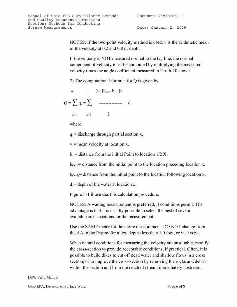
NOTES: If the two-point velocity method is used, v is the arithmetic mean of the velocity at 0.2 and 0.8 dx depth.
If the velocity is NOT measured normal to the tag line, the normal component of velocity must be computed by multiplying the measured velocity times the angle coefficient measured in Part h-10 above
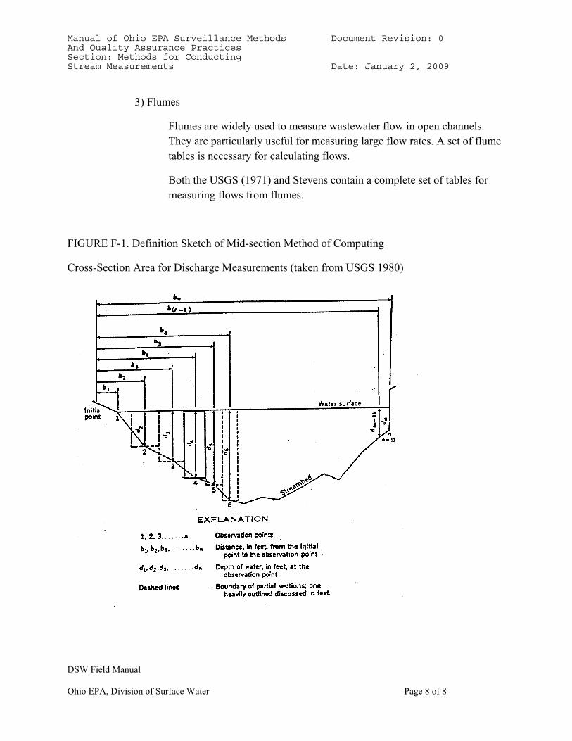
2) The computational formula for Q is given by
n n (vx [bx+1- b x-1])
Q = 3 qx = 3 --------------- dx
x-1 x-1 2
where
qx= discharge through partial section x,
vx= mean velocity at location x,
bx = distance from the initial Point to location 1/2 X,
b(X-l)= distance from the initial point to the location preceding location x.
b(X+l)= distance from the initial point to the location following location x,
dx= depth of the water at location x.
Figure F-1 illustrates this calculation procedure.
NOTES: A wading measurement is preferred, if conditions permit. The advantage is that it is usually possible to select the best of several available cross-sections for the measurement.
Use the SAME meter for the entire measurement. DO NOT change from the AA to the Pygmy for a few depths less than 1.0 foot, or vice versa.
When natural conditions for measuring the velocity are unsuitable, modify the cross-section to provide acceptable conditions, if practical. Often, it is possible to build dikes to cut off dead water and shallow flows in a cross section, or to improve the cross-section by removing the rocks and debris within the section and from the reach of stream immediately upstream.
Manual of Ohio EPA Surveillance Methods Document Revision: 0 And Quality Assurance Practices Section: Methods for Conducting Stream Measurements Date: January 2, 2009
DSW Field Manual
Ohio EPA, Division of Surface Water Page 7 of 8
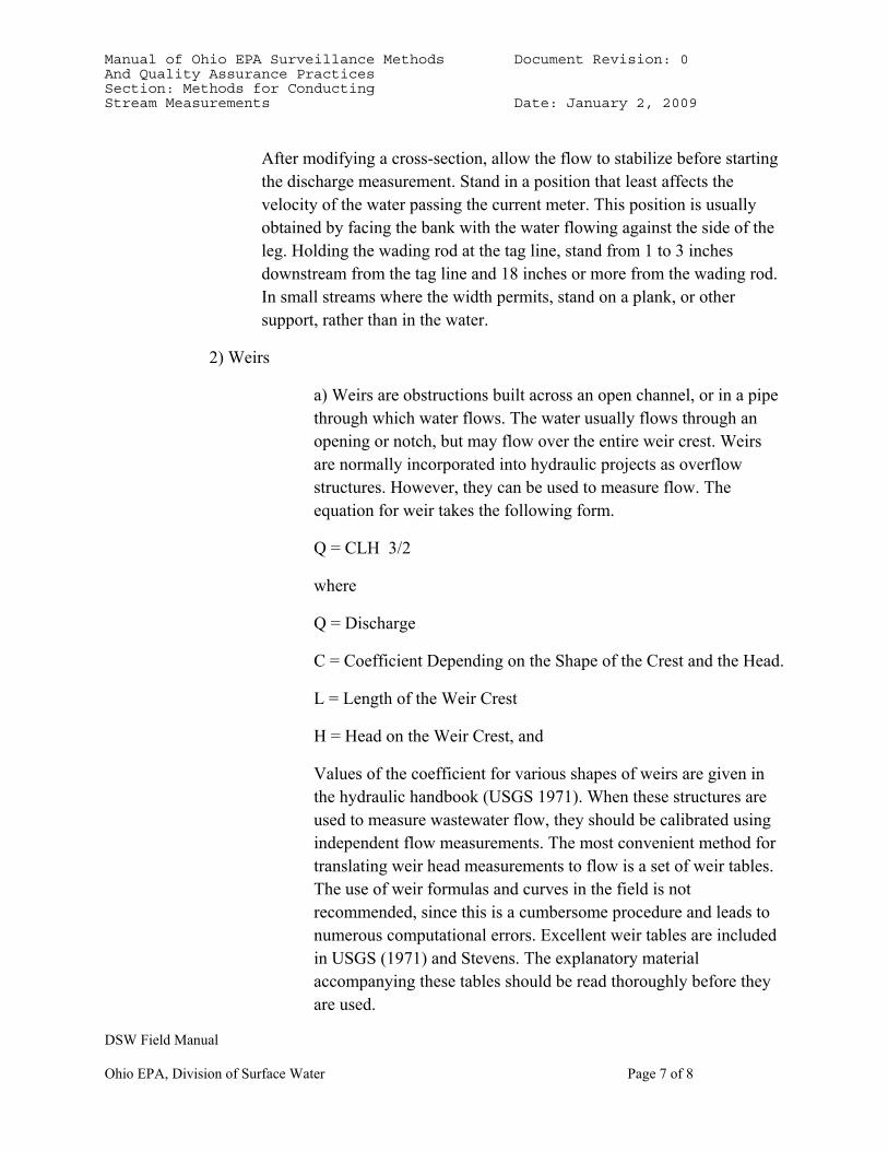
After modifying a cross-section, allow the flow to stabilize before starting the discharge measurement. Stand in a position that least affects the velocity of the water passing the current meter. This position is usually obtained by facing the bank with the water flowing against the side of the leg. Holding the wading rod at the tag line, stand from 1 to 3 inches downstream from the tag line and 18 inches or more from the wading rod. In small streams where the width permits, stand on a plank, or other support, rather than in the water.
2) Weirs
a) Weirs are obstructions built across an open channel, or in a pipe through which water flows. The water usually flows through an opening or notch, but may flow over the entire weir crest. Weirs are normally incorporated into hydraulic projects as overflow structures. However, they can be used to measure flow. The equation for weir takes the following form.
Q = CLH 3/2
where
Q = Discharge
C = Coefficient Depending on the Shape of the Crest and the Head.
L = Length of the Weir Crest
H = Head on the Weir Crest, and
Values of the coefficient for various shapes of weirs are given in the hydraulic handbook (USGS 1971). When these structures are used to measure wastewater flow, they should be calibrated using independent flow measurements. The most convenient method for translating weir head measurements to flow is a set of weir tables. The use of weir formulas and curves in the field is not recommended, since this is a cumbersome procedure and leads to numerous computational errors. Excellent weir tables are included in USGS (1971) and Stevens. The explanatory material accompanying these tables should be read thoroughly before they are used.
Manual of Ohio EPA Surveillance Methods Document Revision: 0 And Quality Assurance Practices Section: Methods for Conducting Stream Measurements Date: January 2, 2009
DSW Field Manual
Ohio EPA, Division of Surface Water Page 8 of 8
3) Flumes
Flumes are widely used to measure wastewater flow in open channels. They are particularly useful for measuring large flow rates. A set of flume tables is necessary for calculating flows.
Both the USGS (1971) and Stevens contain a complete set of tables for measuring flows from flumes.
FIGURE F-1. Definition Sketch of Mid-section Method of Computing
Cross-Section Area for Discharge Measurements (taken from USGS 1980)
Manual of Ohio EPA Surveillance Methods Document Revision: 0 And Quality Assurance Practices Section: Ohio EPA Laboratory Sample Submission/Field Procedures Date: January 2, 2009
DSW Field Manual
Ohio EPA, Division of Surface Water Page 1 of 2
SECTION G. OHIO EPA LABORATORY SAMPLE SUBMISSION/FIELD PROCEDURES
Subsection 1. Sample Containers
Part a) All sample containers must be clearly labeled with the following information:
1) Sampling Location (Stream Name and River Mile or cross road, station number, latitude/longitude reported),
2) Type of sample preservation i.e., H2SO4 (Sulfuric Acid), HNO3 (Nitric Acid), HCl (Hydrochloric Acid), NaOH (Sodium Hydroxide), Na2S2O3 (Sodium Thiosulfate), Na2SO3 (Sodium Sulfite), or "NP" (No Preservative)
3) Date and Time of collection (military time).
Note: whenever there are several trip blanks in the same cooler and sampling involved several individuals, the name of each sample collector must be written on each trip blank label.
Part b) The above information must be written on waterproof labels or on labels created using the CYBERINTERN application, which are then securely attached to all glass containers. The information may also be written on tape or duct tape which has been wrapped around the container, except for VOC vials, which require the use of labels rather than tape. When samples are collected in cubitainers, the information must be written directly on the sample containers with indelible ink or on labels created using the CYBERINTERN application.
Part c) All sample containers should be labeled as completely as possible before beginning the sample collection process to reduce probability of error and improve efficiency in the field.
Subsection 2. Sample Submission Forms
Part a) A separate sample submission form must be filled out for each sampling location.
Part b) The sample submission form must contain all the information recorded on the corresponding sample containers (see Section G, subsection 1, Part a above) plus the following:
Manual of Ohio EPA Surveillance Methods Document Revision: 0 And Quality Assurance Practices Section: Ohio EPA Laboratory Sample Submission/Field Procedures Date: January 2, 2009
DSW Field Manual
Ohio EPA, Division of Surface Water Page 2 of 2
1) all categories in the Sample Information Section must be completed and only one circle should be selected for each category,
2) the Client (Bill To) line must always be completed,
3) the type of sample collected ”grab” or ”composite“ must be indicated,
4) the sample Collection Date and time should be completed using military time format,
5) the frequency and duration of composite sample (where applicable), or the number of grab sub-samples/composite
6) the Container Information subsection enables DES to verify that the correct containers were submitted for each parameter requested so this subsection should be accurately completed.
7) when applicable, the appropriate circle Field QC should be checked.
8) the Customer ID is an internal code provided by DES to each sample collector. It enables the collector to collocate inorganic and organic samples from the same site. This ID should be recorded on both inorganic and organic sample submission forms.
9) the Station ID field should be used to record the Ohio set STORET code.
10) the information in the Sample Location section should correspond to what was recorded on the sample container,
11) the Template name should be indicated or parameters may be selected from the list (parameters in the template should not be selected twice). If parameters are to be deleted from the template for a particular site, the parameter should be crossed out on the sample submission form and initialed by the staff member making the change.
The back page of the sample submission form and the ”Ohio EPA Field Sampling Handbook“ may be consulted for additional information.
Part c) All sample submission forms should be filled out as completely as possible before beginning the sample collection process in order to minimize confusion and clerical work in the field.
Manual of Ohio EPA Surveillance Methods Document Revision: 0 And Quality Assurance Practices Section: Ohio EPA Laboratory Documented Custody Procedures Date: January 2, 2009
DSW Field Manual
Ohio EPA, Division of Surface Water Page 1 of 1
SECTION H. OHIO EPA LABORATORY DOCUMENTED CUSTODY PROCEDURES
Subsection 1. General
Whenever samples are collected, formal documented procedures for sample handling MUST be followed. The primary objective of these procedures is to create an accurate, written record which can be used to trace the possession and handling of the sample from the moment of its collection through its introduction as evidence.
Subsection 2. Definitions
Part a) Sample custody - A sample is in your custody if:
1) it is in your physical possession; or
2) it is in your view, after being in your physical possession; or
3) it was in your physical possession and you locked it in a transfer-proof container or storage area." (U.S. EPA 1976).
Part b) Transfer of sample custody - A transfer of custody occurs whenever a sample, or group of samples:
1) passes from the physical possession of one person to another, or;
2) is removed from a transfer-proof container, or storage area, by a person other than the person who put the sample(s) in said container or storage area.
Subsection 3. Transfer of Custody Procedures
Each time the custody of a sample or group of samples is transferred, the person relinquishing custody of the sample(s) must sign, date, and record the military time on a "transfer of custody" form. The form should also indicate the number of samples being transferred, the parameters to be analyzed, and a brief description of the origin of the sample(s). The person receiving custody of the samples must also sign, date, and record the military time on the DES "Chemistry Laboratory Chain of Custody Report" form. Both persons should keep a copy of the transfer form. The laboratory data sheets must be transferred with the samples.
Manual of Ohio EPA Surveillance Methods Document Revision: 0 And Quality Assurance Practices Section: List of Tables Date: January 2, 2009
DSW Field Manual
Ohio EPA, Division of Surface Water Page 1 of 1
SECTION I. LIST OF TABLES
D-1. Variation of pH with Temperature
D-2. Temperature versus Conductivity
E-1. Conventional Parameters, Sample Preservation and Maximum Holding Times
E-2. Organic Parameters, Sample Preservation and Maximum Holding Times
F-1. Current Meter and Velocity Measurement, Method for Various Depths II
Manual of Ohio EPA Surveillance Methods Document Revision: 0 And Quality Assurance Practices Section: List of Figures Date: January 2, 2009
DSW Field Manual
Ohio EPA, Division of Surface Water Page 1 of 1
SECTION J. LIST OF FIGURES
F-1. Definition Sketch of Midsection Method of Computing Cross-Section Area for Discharge Measurements (taken from USGS 1980)
Manual of Ohio EPA Surveillance Methods Document Revision: 0 And Quality Assurance Practices Section: Literature Cited Date: January 2, 2009
DSW Field Manual
Ohio EPA, Division of Surface Water Page 1 of 2
SECTION K. LITERATURE CITED
American Public Health Association et. al. 1998. Standard Methods for the Examination of Water and Wastewater. 20th Edition.
American Society for Testing and Materials. 1977. Annual Book of ASTM Standards. Part 31 - Water. Philadelphia
Inter-Agency Committee on Water Resources, Subcommittee on Sedimentation. 1963. A Study of Methods Used in Measurement and Analysis of Sediment Loads in Streams - Report No. 14 Determination of Fluvial Sediment Discharge .
Leopold Stevens, Incorporated. Stevens Water Resource Data Book, 2nd Ed. Beaverton. Oregon.
Ohio Environmental Protection Agency. 1976. Manual of Sampling, Analytical, and Reporting Procedures for Wastewaters.
Ohio Environmental Protection Agency. 2008. Ohio EPA Field Sampling Handbook. Division of Environmental Services.
Ohio Environmental Protection Agency. 2008. Flow Measurement Training- Using the SonTek FlowTracker, Division of Surface Water, Modeling & Assessment Section (unpublished document).
Sontek/YSI, Inc. 2006. Flowtracker Handheld ADV User’s Firmware Version 3.1.
USGS. 1968. Techniques of Water-Resources Investigations of the United States Geological Survey. Chapter B2.
USGS. 1971. Water Measurement Manual.
USGS. 1980. Techniques of Water-Resources Investigations of the United States Geological Survey. "Discharge Measurements at Gaging Stations." Chapter A8.
USGS. 2004. Office of Surface Water Technical Memorandum 2004.04.
USGS. 2007. Office of Surface Water Technical Memorandum 2007.01.
U.S. Environmental Protection Agency. 1976. Minimum Requirements for Water Quality Assurance Program.
U.S. Environmental Protection Agency. 1977. NPDES Compliance Sampling Inspection Manual.
U.S. Environmental Protection Agency. 1977. NPDES Compliance Sampling Inspection Manual.
Manual of Ohio EPA Surveillance Methods Document Revision: 0 And Quality Assurance Practices Section: Literature Cited Date: January 2, 2009
DSW Field Manual
Ohio EPA, Division of Surface Water Page 2 of 2
U.S. Environmental Protection Agency. 2007. Federal Register. Vol.72, No.57. Part III. 40 CFR Parts 136 and 503.
Welch. S. 1948. Limnological Methods. Chapter 14. McGraw-Hill Book Co.
Youden, W.J. 1973. Statistical Techniques for Collaborative Tests. Assn. of Official Analytical Chemists, Washington, D.