Embed Size (px)
Citation preview
pag. 1 / 12
MANUALE OPERATIVO / INSTRUCTION MANUAL IM457-IU v0.1
EMM-4L Multimetro digitale
EMM-4L Digital multimeter
pag. 2 / 12
ATTENZIONE!!!
• Leggere attentamente il manuale prima dell’utilizzo e l’installazione.
• Questi strumenti devono essere installati da personale qualificato, nel
rispetto delle vigenti normative impiantistiche, allo scopo di evitare danni
a persone o cose.
• Prima di qualsiasi intervento sullo strumento, togliere tensione dagli
ingressi di alimentazione e dalle uscite relè dove presenti.
• Il costruttore non si assume responsabilità in merito alla sicurezza
elettrica in caso di utilizzo improprio del dispositivo.
• I prodotti descritti in questo documento sono suscettibili in qualsiasi
momento di evoluzioni o di modifiche.
Introduzione Il multimetro EMM-4L è ideale per unire la massima semplicità di utilizzo con
funzionalità di analisi avanzate. In esecuzione per montaggio da fronte
quadro con dimensioni standard 96x96mm, ha un design moderno nel
frontale e con la sua profondità ridotta, facilita il montaggio anche nel caso di
spazi ridotti all’interno del quadro elettrico.
Il display retroilluminato LCD consente un’interfaccia chiara ed intuitiva ed
una facilità di lettura in ogni condizione di illuminazione. L’EMM-4L è inoltre
dotato di un’interfaccia di comunicazione RS-485 con protocollo Modbus,
facilitando la sua integrazione in sistemi di supervisione.
Descrizione • Multimetro digitale trifase
• Montaggio a pannello, contenitore standard 96x96mm
• Display LCD retroilluminato
• 4 tasti di navigazione per funzioni ed impostazioni
• Interfaccia di comunicazione RS485 incorporata (Modbus RTU)
• Uscita impulsi (opzionale)
• Misure in vero valore efficace (TRMS)
• Vasta gamma di misure disponibili, inclusive di THD di tensione e di
corrente
• Alimentazione ausiliaria ad ampio range di tensione (85-264 VCA)
• Programmazione dal fronte
• Protezione impostazioni via password
• Montaggio senza necessità di utensili
Funzione dei tasti frontali Tasto ENTER – Serve per entrare nei vari menu o per confermare una scelta
effettuata, per lo scorrimento delle sotto-pagine delle misure di tensione e
corrente.
Tasto – Serve per la selezione fra le possibili scelte presentate a display,
per uscire dai vari menu e per lo scorrimento delle sotto-pagine delle misure
di THD.
Tasto – Serve per la modifica delle impostazioni (incremento), per lo
scorrimento delle sotto-pagine delle misure di potenza e sommatorie.
Tasto – Serve per la modifica delle impostazioni (decremento), per lo
scorrimento delle sotto-pagine delle misure di energia.
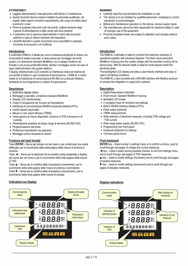
Indicazioni sul display
WARNING!
• Carefully read the manual before the installation or use.
• This device is to be installed by qualified personnel, complying to current
standards, to avoid damages.
• Before any maintenance operation on the device, remove supply inputs.
• The manufacturer cannot be held responsible for electrical safety in case
of improper use of the equipment.
• Products illustrated herein are subject to alteration and changes without
prior notice.
Introduction The EMM-4L multimeter is ideal to combine the maximum easiness of
operations together with advanced features. The flush mount execution
96x96mm housing joins the modern disegn with the tool-less mouting oft he
device body. With its reduced depth is ideal for small spaces inside the
electrical panel.
The backlighted LCD display provides a user-friendly interface and easy to
read in all lighting conditions.
The EMM-4L is also provided with a RS-485 interface with Modbus protocol
to consent the integration in supervision systems..
Description • Digital three-phase multimeter
• Flush-mount, standard 96x96mm housing
• Backlight LCD screen
• 4 navigation keys for functions and settings
• Built-in RS485 interface (Modbus RTU)
• Pulse output (optional)
• TRMS measurements
• Wide selection of electrical measures, including THD voltage and
THD current
• Wide range power supply (85-264 VAC)
• Programming from front panel
• Password protection for settings
• Tool-less panel mount
Front keyboard ENTER key – Used to enter in settings menu or to confirm a choice, used to
scroll through sub-pages of voltage and current measures.
key – Used to select among possible choices, to exit from settings menu
and to scroll through sub-pages of THD measures.
key – Used to modify settings (increment) and to scroll through sub-pages
of powers measures.
key – Used to modify settings (decrement) and to scroll through sub-
pages of energies measures.
Display indications
Display principale misure
Comunicazione attiva
Indicazione fase selezionata
Display energie
Indicazione unità misura
Indicazione THD
Main display for measures
Communication active
Indication of selected phase
Energy display
Indication of unit measure
Indication of THD
pag. 3 / 12
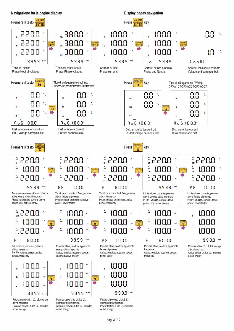
Navigazione fra le pagine display
Premere il tasto
Premere il tasto
Premere il tasto
Display pages navigation
Press key
Press key
Press key
Tipo di collegamento / Wiring: 1P2W-1P3W-3P4W1CT-3P4W3CT
Tipo di collegamento / Wiring: 3P3W1CT-3P3W2CT-3P3W3CT
L-L tensione, corrente, potenza attiva, frequenza PH-PH voltage, current, active power, frequency
Potenza attiva, reattiva, apparente energia attiva importata Active, reactive, apparent power, imported active energy
Potenza attiva, reattiva, apparente, fattore di potenza Active, reactive, apparent power, power factor
Potenza attiva, reattiva, apparente, frequenza Active, reactive, apparent power, frequency
Potenza attiva L1, L2, L3, energia attiva importata Active power L1, L2, L3, imported active energy
Tensione e corrente di fase, potenza attiva, energia attiva importata Phase voltage and current, active power, imp. active energy.
Tensione e corrente di fase, potenza attiva, fattore di potenza Phase voltage and current, active power, power factor
Tensione e corrente di fase, potenza attiva, frequenza Phase voltage and current, active power, frequency
L-L tensione, corrente, potenza attiva, energia attiva importata PH-PH voltage, current, active power, imp. active energy.
L-L tensione, corrente, potenza attiva, fattore di potenza PH-PH voltage, current, active power, power factor.
Dist. armonica tensioni L-N PH-L voltage harmonic dist.
Dist. armonica correnti Current harmonic dist.
Dist. armonica tensioni L-L PH-PH voltage harmonic dist.
Dist. armonica correnti Current harmonic dist.
Tensioni di fase Phase-Neutral voltages
Tensioni concatenate Phase-Phase voltages
Correnti di fase Phase currents
Correnti di fase e neutro Phase and Neutral currents
Sbilanc. tensione e corrente Voltage and current unbal.
Potenza reattiva L1, L2, L3, energia attiva importata Reactive power L1, L2, L3, imported active energy
Potenza apparente L1, L2, L3, energia attiva importata Apparent power L1, L2, L3, imported active energy
Fattore di potenza L1, L2, L3, energia attiva importata Power factor L1, L2, L3, imported active energy
pag. 4 / 12
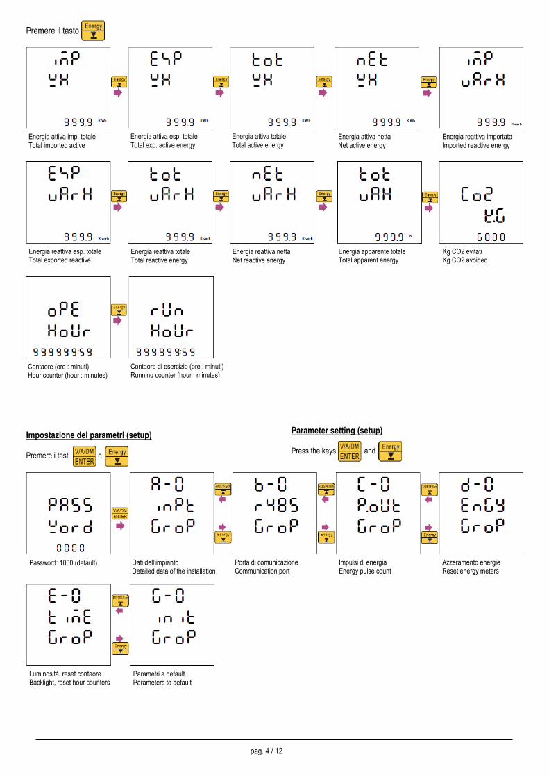
Premere il tasto
Impostazione dei parametri (setup)
Premere i tasti e
Parameter setting (setup)
Press the keys and
Energia attiva imp. totale Total imported active energy
Energia attiva esp. totale Total exp. active energy
Energia attiva totale Total active energy
Energia attiva netta Net active energy
Energia reattiva importata Imported reactive energy
Contaore (ore : minuti) Hour counter (hour : minutes)
Contaore di esercizio (ore : minuti) Running counter (hour : minutes)
Energia reattiva esp. totale Total exported reactive energy
Energia reattiva totale Total reactive energy
Energia reattiva netta Net reactive energy
Energia apparente totale Total apparent energy
Kg CO2 evitati Kg CO2 avoided
Luminosità, reset contaore Backlight, reset hour counters
Parametri a default Parameters to default
Password: 1000 (default) Dati dell’impianto Detailed data of the installation
Porta di comunicazione Communication port
Impulsi di energia Energy pulse count
Azzeramento energie Reset energy meters
pag. 5 / 12
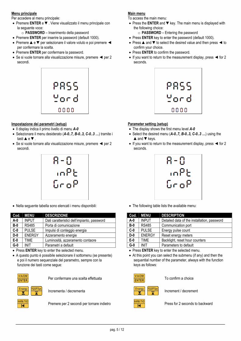
Menu principale
Per accedere al menu principale:
• Premere ENTER e . Viene visualizzato il menu principale con
la seguente voce:
o PASSWORD – Inserimento della password
• Premere ENTER per inserire la password (default 1000).
• Premere e per selezionare il valore voluto e poi premere
per confermare la scelta.
• Premere ENTER per confermare la password.
• Se si vuole tornare alla visualizzazione misure, premere per 2
secondi.
Impostazione dei parametri (setup)
• Il display indica il primo livello di menu A-0
• Selezionare il menu desiderato (A-0..7, B-0..3, C-0..3 …) tramite i
tasti e .
• Se si vuole tornare alla visualizzazione misure, premere per 2
secondi.
• Nella seguente tabella sono elencati i menu disponibili:
Cod. MENU DESCRIZIONE
A-0 INPUT Dati caratteristici dell’impianto, password
B-0 RS485 Porta di comunicazione
C-0 PULSE Impulsi di conteggio energia
D-0 ENERGY Azzeramento energie
E-0 TIME Luminosità, azzeramento contaore
G-0 INIT Parametri a default
• Press ENTER key to enter the selected menu.
• A questo punto è possibile selezionare il sottomenu (se presente)
e poi il numero sequenziale del parametro, sempre con la
funzione dei tasti come segue:
Per confermare una scelta effettuata
Incrementa / decrementa
Premere per 2 secondi per tornare indietro
Main menu
To access the main menu:
• Press the ENTER and key. The main menu is displayed with
the following choice:
o PASSWORD – Entering the password
• Press ENTER key to enter the password (default 1000).
• Press and to select the desired value and then press to
confirm your choice.
• Press ENTER to confirm the password.
• If you want to return to the measurement display, press for 2
seconds.
Parameter setting (setup)
• The display shows the first menu level A-0
• Select the desired menu (A-0..7, B-0..3, C-0..3 …) using the
and keys.
• If you want to return to the measurement display, press for 2
seconds.
• The following table lists the available menu:
Cod. MENU DESCRIPTION
A-0 INPUT Detailed data of the installation, password
B-0 RS485 Communication port
C-0 PULSE Energy pulse count
D-0 ENERGY Reset energy meters
E-0 TIME Backlight, reset hour counters
G-0 INIT Parameters to default
• Press ENTER key to enter the selected menu.
• At this point you can select the submenu (if any) and then the
sequential number of the parameter, always with the function
keys as follows:
To confirm a choice
Increment / decrement
Press for 2 seconds to backward
pag. 6 / 12
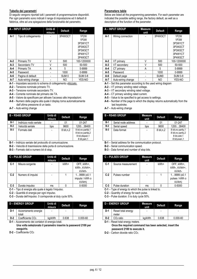
Tabella dei parametri Di seguito vengono riportati tutti i parametri di programmazione disponibili.
Per ogni parametro sono indicati il range di impostazione ed il default di
fabbrica, oltre ad una spiegazione della funzionalità del parametro.
A – INPUT GROUP Unità di
misura Default Range
A-1 Tipo di collegamento - 3P4W3CT 1P2W
1P3W
3P3W1CT
3P3W2CT
3P3W3CT
3P4W1CT
3P4W3CT
A-2 Primario TV V 500 100-1200000
A-3 Secondario TV V 500 50-500
A-4 Primario TA A 5 5-9999
A-5 Password - 1000 0-9999
A-6 Pagina di default - SUM 0 SUM 0-8
A-7 Auto-wiring change - NO YES-NO
A-1 – Impostare secondo lo schema di collegamento utilizzato.
A-2 – Tensione nominale primario TV.
A-3 – Tensione nominale secondario TV.
A-4 – Corrente nominale del primario dei TA.
A-5 – Valore da specificare per attivare l’accesso alle impostazioni.
A-6 – Numero della pagina alla quale il display torna automaticamente
dall’ultima pressione di un tasto.
A-7 – Auto-wiring change
B – RS485 GROUP Unità di
misura Default Range
B-1 Indirizzo nodo seriale - 01 01-247 B-2 Velocità seriale bps 9600 1200…38400 B-3 Formato dati - 8 bit,n,2 8 bit,no parità,1
8 bit,no parità,2 8 bit,dispari,1
8 bit,pari,1
B-1 – Indirizzo seriale del protocollo di comunicazione.
B-2 – Velocità di trasmissione della porta di comunicazione.
B-3 – Formato dati e numero bit di stop.
C – PULSE GROUP Unità di
misura Default Range
C-1 Misura sorgente - kWh+ OFF, kWh+,
kWh-, kVArh+,
kVArh- C-2 Numero di impulsi - 1 1…9999 (x0.1
impulsi / kWh o
kVArh)
C-3 Durata impulso ms 0 0-5000
C-1 – Tipo di energia alla quale è legato l’impulso.
C-2 – Quantità di energia per ogni impulso.
C-3 – Durata dell‘impulso. 0 corrisponde al duty cycle 50%.
D – ENERGY GROUP Unità di
misura Default Range
D-1 Azzerramento energie
totali
- - -
D-2 Coefficiente CO2 kg/kWh 0.638 0.000-60
D-1 – Azzeramento dei contatori di energia totali.
Una volta selezionato il parametro inserire la password 2100 per
eseguirlo. D-2 – Coefficiente CO2
Parameters table Below are listed all the programming parameters. For each parameter are
indicated the possible setting range, the factory default, as well as a
description of the function of the parameter.
A – INPUT GROUP Measure
unit Default Range
A-1 Wiring connection - 3P4W3CT 1P2W
1P3W
3P3W1CT
3P3W2CT
3P3W3CT
3P4W1CT
3P4W3CT
A-2 VT primary V 500 100-1200000
A-3 VT secondary V 500 50-500
A-4 CT primary A 5 5-9999
A-5 Password - 1000 0-9999
A-6 Default page - SUM0 SUM 0-8
A-7 Auto-wiring change - NO YES-NO
A-1 – Set this parameter according to the used wiring diagram
A-2 – VT primary winding rated voltage.
A-3 – VT secondary winding rated voltage.
A-4 – CT primary winding rated current.
A-5 – Value to be specified to get access to settings.
A-6 – Number of the page to which the display returns automatically from the
last keystroke.
A-7 – Auto-wiring change
B – RS485 GROUP Measure
unit Default Range
B-1 Serial node address - 01 01-247 B-2 Serial speed bps 9600 1200…38400 B-3 Data format - 8 bit,n,2 8 bit,no parity,1
8 bit,no parity,2 8 bit,odd,1 8 bit,even,1
B-1 – Serial address for the communication protocol.
B-2 – Serial communication speed.
B-3 – Data format and number of stop bits.
C – PULSES GROUP Measure
unit Default Range
C-1 Source measurement - kWh+ OFF, kWh+,
kWh-, kVArh+,
kVArh-
C-2 Pulses number - 1 1…9999 (x0.1
pulses / kWh o
kVArh)
C-3 Pulse duration ms 0 0-5000
C-1 – Type of energy to which the pulse is linked to.
C-2 – Quantity of energy for each pulse.
C-3 – Pulse duration. 0 is duty cycle 50%.
D – ENERGY GROUP Measure
unit Default Range
D-1 Reset total energy
meter
- - -
D-2 CO2 ratio kg/kWh 0.638 0.000-60
D-1 – Reset total energy meters.
Once the required command has been selected, insert the
password 2100 to execute it. D-2 – Carbon dioxide ratio CO2.
pag. 7 / 12
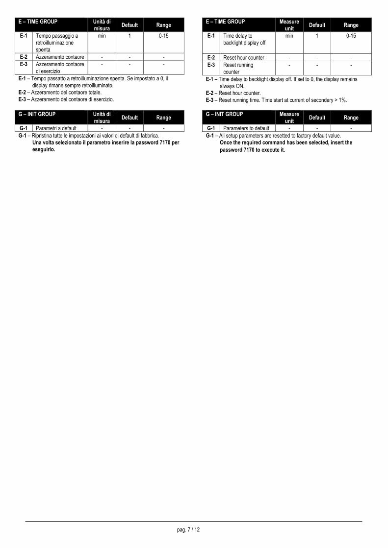
E – TIME GROUP Unità di
misura Default Range
E-1 Tempo passaggio a
retroilluminazione
spenta
min 1 0-15
E-2 Azzeramento contaore - - -
E-3 Azzeramento contaore
di esercizio
- - -
E-1 – Tempo passatto a retroilluminazione spenta. Se impostato a 0, il
display rimane sempre retroilluminato.
E-2 – Azzeramento del contaore totale.
E-3 – Azzeramento del contaore di esercizio.
G – INIT GROUP Unità di
misura Default Range
G-1 Parametri a default - - -
G-1 – Ripristina tutte le impostazioni ai valori di default di fabbrica.
Una volta selezionato il parametro inserire la password 7170 per
eseguirlo.
E – TIME GROUP Measure
unit Default Range
E-1 Time delay to
backlight display off
min 1 0-15
E-2 Reset hour counter - - -
E-3 Reset running
counter
- - -
E-1 – Time delay to backlight display off. If set to 0, the display remains
always ON.
E-2 – Reset hour counter. E-3 – Reset running time. Time start at current of secondary > 1%.
G – INIT GROUP Measure
unit Default Range
G-1 Parameters to default - - -
G-1 – All setup parameters are resetted to factory default value.
Once the required command has been selected, insert the
password 7170 to execute it.
pag. 8 / 12
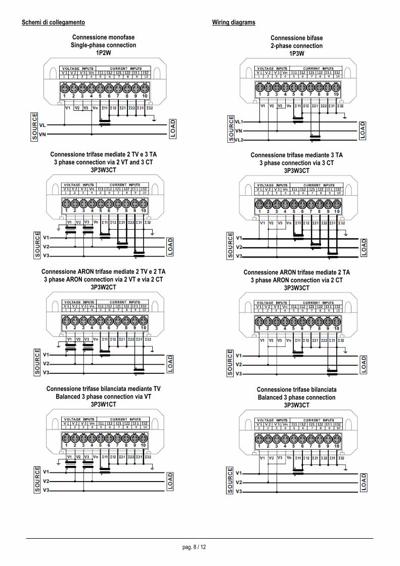
Schemi di collegamento
Connessione monofase Single-phase connection
1P2W
Connessione trifase mediate 2 TV e 3 TA 3 phase connection via 2 VT and 3 CT
3P3W3CT
Connessione ARON trifase mediate 2 TV e 2 TA 3 phase ARON connection via 2 VT e via 2 CT
3P3W2CT
Connessione trifase bilanciata mediante TV Balanced 3 phase connection via VT
3P3W1CT
Wiring diagrams
Connessione bifase 2-phase connection
1P3W
Connessione trifase mediante 3 TA 3 phase connection via 3 CT
3P3W3CT
Connessione ARON trifase mediate 2 TA 3 phase ARON connection via 2 CT
3P3W3CT
Connessione trifase bilanciata Balanced 3 phase connection
3P3W3CT
pag. 9 / 12
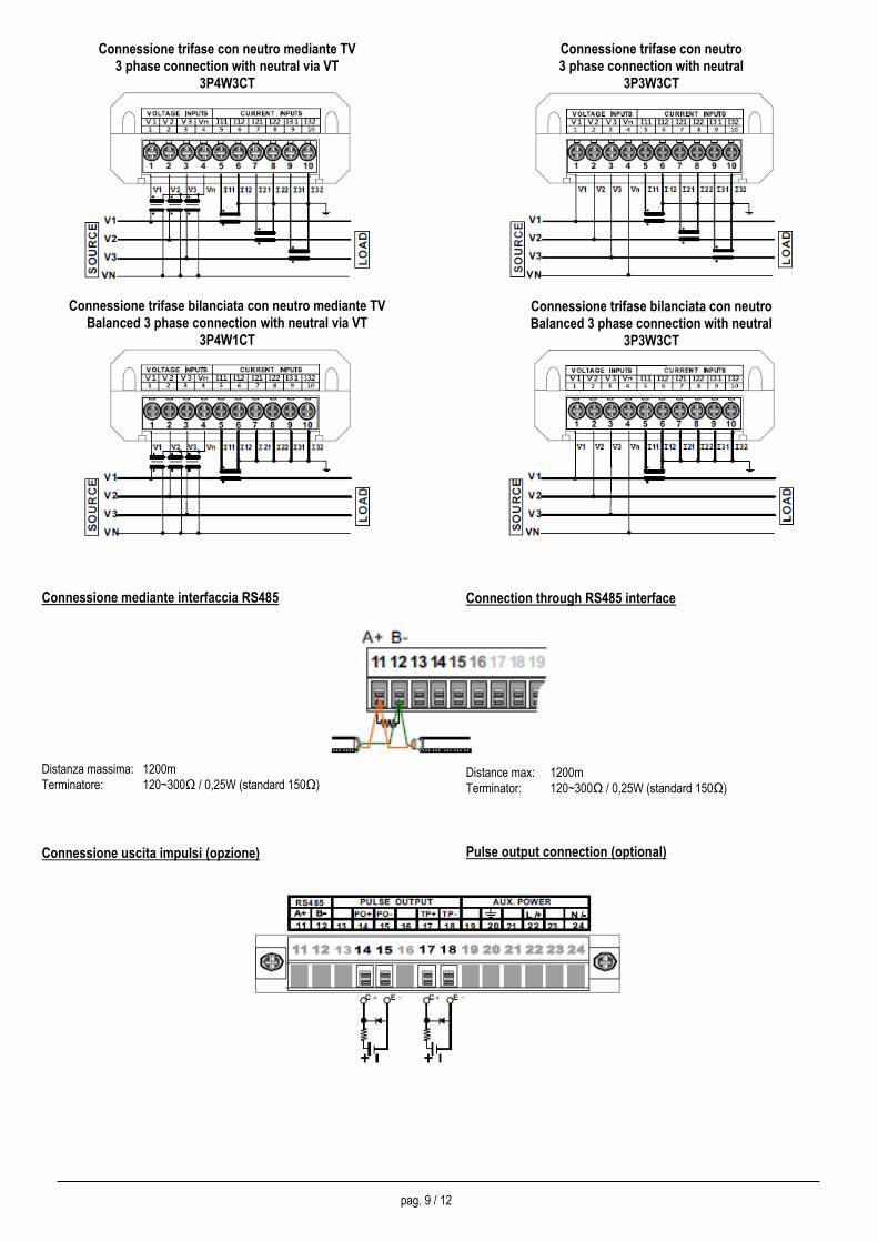
Connessione trifase con neutro mediante TV 3 phase connection with neutral via VT
3P4W3CT
Connessione trifase bilanciata con neutro mediante TV Balanced 3 phase connection with neutral via VT
3P4W1CT
Connessione mediante interfaccia RS485
Distanza massima: 1200m
Terminatore: 120~300Ω / 0,25W (standard 150Ω)
Connessione uscita impulsi (opzione)
Connessione trifase con neutro 3 phase connection with neutral
3P3W3CT
Connessione trifase bilanciata con neutro Balanced 3 phase connection with neutral
3P3W3CT
Connection through RS485 interface
Distance max: 1200m
Terminator: 120~300Ω / 0,25W (standard 150Ω)
Pulse output connection (optional)
pag. 10 / 12
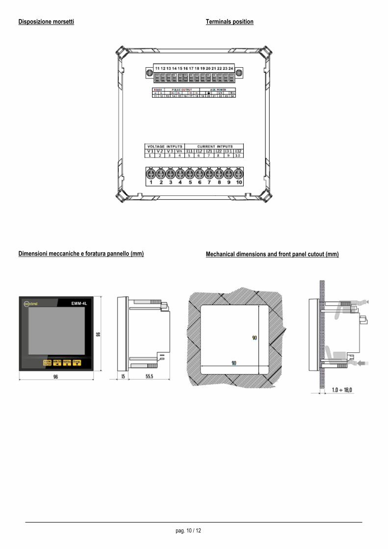
Disposizione morsetti
Dimensioni meccaniche e foratura pannello (mm)
Terminals position
Mechanical dimensions and front panel cutout (mm)
pag. 11 / 12
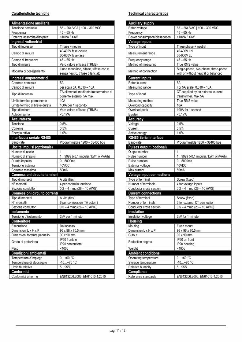
Caratteristiche tecniche
Alimentazione ausiliaria Tensione nominale 85 – 264 VCA | 100 – 300 VCC
Frequenza 45 – 65 Hz
Potenza assorbita/dissipata <10VA / <3W
Ingressi voltmetrici Tipo di ingresso Trifase + neutro
Campo di misura 40-400V fase-neutro
60-600V fase-fase
Campo di frequenza 45 – 65 Hz
Tipo di misura Vero valore efficace (TRMS)
Modalità di collegamento Linea monofase, bifase, trifase con e
senza neutro, trifase bilanciato
Ingressi amperometrici Corrente nominale 5A
Campo di misura per scala 5A: 0,010 – 10A
Tipo di ingresso TA alimentati mediante trasformatore di
corrente esterno. 5A max
Limite termico permanente 10A
Limite termico di breve durata 100A per 1 secondo
Tipo di misura Vero valore efficace (TRMS)
Autoconsumo <0,1VA
Accuratezza Tensione 0,5%
Corrente 0,5%
Energia attiva 1,0%
Interfaccia seriale RS485 Baud-rate Programmabile 1200 – 38400 bps
Uscita impulsi (opzionale) Numero di uscite 1
Numero di impulsi 1…9999 (x0.1 impulsi / kWh o kVArh)
Durata impulso 0…5000ms
Tensione esterna 40VCC
Corrente massima 50mA
Connessioni circuito tensioni Tipo di morsetti A vite (fissi)
N° morsetti 4 per controllo tensione
Sezione conduttori 0,2 – 4 mmq (26 – 10 AWG)
Connessioni circuito correnti Tipo di morsetti A vite (fissi)
N° morsetti 6 per connessioni TA esterni
Sezione conduttori 0,5 – 4 mmq (26 – 10 AWG)
Isolamento Tensione d‘isolamento 2kV per 1 minuto
Contenitore Esecuzione Da incasso
Dimensioni L x H x P 96 x 96 x 70,5 mm
Dimensioni foratura pannello 90 x 90 mm
Grado di protezione IP50 frontale
IP20 contenitore
Peso <400g
Condizioni ambientali Temperatura d’impiego 0…+60 °C
Temperatura di stoccaggio -10…+70 °C
Umidità relativa 5…95%
Conformità Conformità a norme EN613206:2006, EN61010-1:2010
Technical characteristics
Auxiliary supply Rated voltage 85 – 264 VAC | 100 – 300 VDC
Frequency 45 – 65 Hz
Power consumption/dissapation <10VA / <3W
Voltage inputs Type of input Three phase + neutral
Measurement range 40-400V LN
60-600V LL
Frequency range 45 – 65 Hz
Method of measuring True RMS value
Method of connection Single-phase, two-phase, three-phase
with or without neutral or balanced
Current inputs Rated current 5A
Measuring range For 5A scale: 0,010 – 10A
Type of input CT supplied by an external current
transformer. Max 5A
Measuring method True RMS value
Overload capacity 10A
Overload peak 100A for 1 second
Burden <0,1VA
Accuracy Voltage 0,5%
Current 0,5%
Active energy 1,0%
RS485 Serial interface Baud-rate Programmable 1200 – 38400 bps
Pulses output (optional) Output number 1
Pulse number 1…9999 (x0.1 impulsi / kWh o kVArh)
Pulse duration 0…5000ms
External voltage 40VDC
Max current 50mA
Voltage input connections Type of terminal Screw (fixed)
Number of terminals 4 for voltage inputs
Conductor cross section 0,2 – 4 mmq (26 – 10 AWG)
Current connections Type of terminal Screw (fixed)
Number of terminals 6 for external CT connection
Conductor cross section 0,5 – 4 mmq (26 – 10 AWG)
Insulation Insulation voltage 2kV for 1 minute
Housing Mouting Flush mount
Dimension L x H x P 96 x 96 x 70,5 mm
Cutout 90 x 90 mm
Protection degree IP50 on front
IP20 housing
Weight <400g
Ambient conditions Operating temperature 0…+60 °C
Storage temperature -10…+70 °C
Relative humidity 5…95%
Compliance Reference standards EN613206:2006, EN61010-1:2010

pag. 12 / 12
Per ulteriori informazioni contattare:
Contrel elettronica s.r.l.
Via San Fereolo, 9
I-26900 Lodi
Tel: +39 0371 30207 / 30761 / 35386
Fax: +39 0371 32819
E-Mail: [email protected]
www.contrel.it
For further details please contact: