Embed Size (px)
Citation preview
Matrix Decompositions and
Quantum Circuit Design
Stephen S. Bullock(joint with Vivek V.Shende,Igor L.Markov, U.M. EECS)
Mathematical andComputational Sciences Division
Division SeminarNational Institute of Standards and Technology
September 15, 2004
1
Motivation
Classical Technique: For AND-OR-NOT circuit for function ϕ on bit strings
� Build AND-NOT circuit firing on each bit-string with ϕ � 1
� Connect each such with an OR
Restatement:
� Produce a decomposition of the function ϕ
� Produce circuit blocks accordingly
2
Motivation, Cont.
Quotation, Feynman on Computation,
�
2.4:
However, the approach described here is so simple and generalthat it does not need an expert in logic to design it! Moreover, it isalso a standard type of layout that can easily be laid out in silicon.(ibid.)
Remarks:
� Analog for quantum computers?
� Simple & general?
3
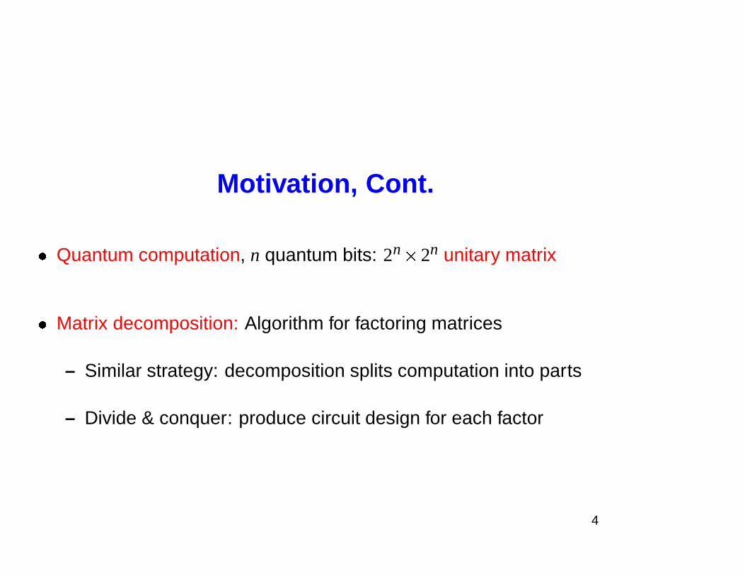
Motivation, Cont.
� Quantum computation, n quantum bits: 2n
� 2n unitary matrix
� Matrix decomposition: Algorithm for factoring matrices
– Similar strategy: decomposition splits computation into parts
– Divide & conquer: produce circuit design for each factor
4
Outline
I. Introduction to Quantum CircuitsII. Two Qubit Circuits (CD)
III. Circuits for Diagonal UnitariesIV. Half CNOT per Entry (CSD)V. Differntial Topology & Lower Bounds
5
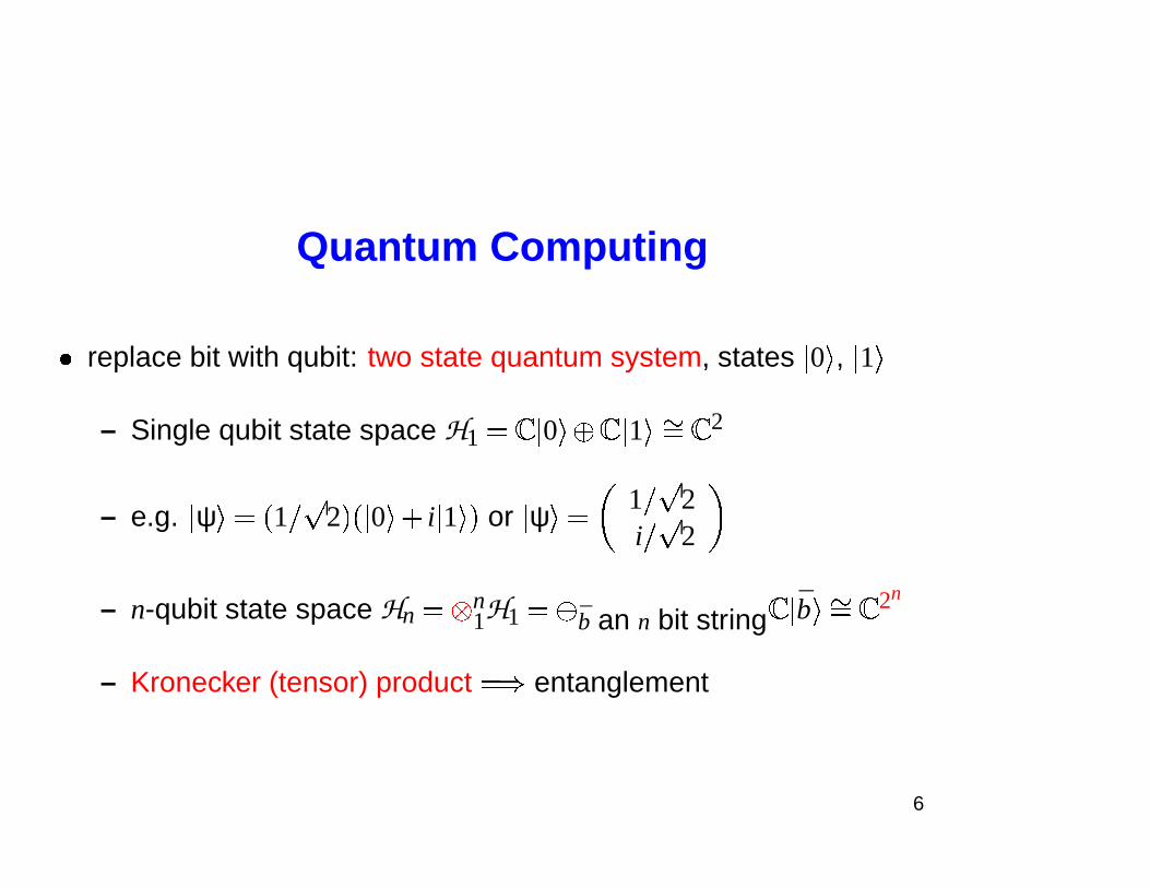
Quantum Computing
� replace bit with qubit: two state quantum system, states � 0 � , � 1 �
– Single qubit state space H1 � � � 0 ��� � � 1 ��� � � 2
– e.g. � ψ � � � 1 � 2 � � � 0 ��� i � 1 � � or � ψ � �
1 � 2i � 2
– n-qubit state space Hn � n1H1 � � b an n bit string � � b �� � � 2n
– Kronecker (tensor) product � � entanglement
6
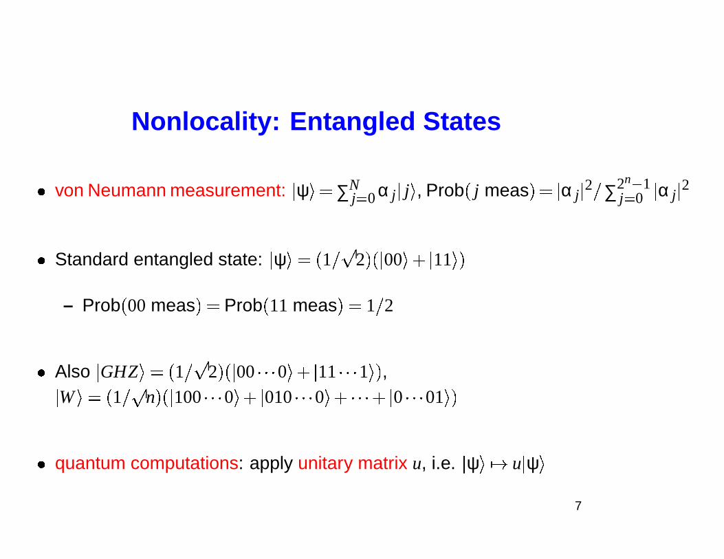
Nonlocality: Entangled States
� von Neumann measurement: � ψ � � ∑Nj� 0 α j � j � , Prob � j meas � � � α j � 2 � ∑2n � 1
j� 0 � α j � 2
� Standard entangled state: � ψ � � � 1 � 2 � � � 00 � � � 11 � �
– Prob � 00 meas � � Prob � 11 meas � � 1 � 2
� Also � GHZ � � � 1 � 2 � � � 00 � � � 0 ��� � 11 � � � 1 � � ,
�W � � � 1 � n � � � 100 � � � 0 ��� � 010 � � � 0 ��� � � �� � 0 � � � 01 � �
� quantum computations: apply unitary matrix u, i.e. � ψ ��� � u � ψ �7
Tensor (Kronecker) Productsof Data, Computations
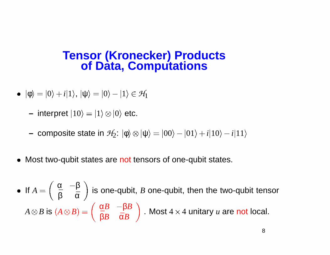
� � φ � � � 0 ��� i � 1 � , � ψ � � � 0 ��� � 1 ��� H1
– interpret � 10 � � � 1 � � 0 � etc.
– composite state in H2: � φ � � ψ � � � 00 � � � 01 ��� i � 10 ��� i � 11 �
� Most two-qubit states are not tensors of one-qubit states.
� If A �
α � ββ α is one-qubit, B one-qubit, then the two-qubit tensor
A B is � A B � �
αB � βBβB αB
. Most 4 � 4 unitary u are not local.
8
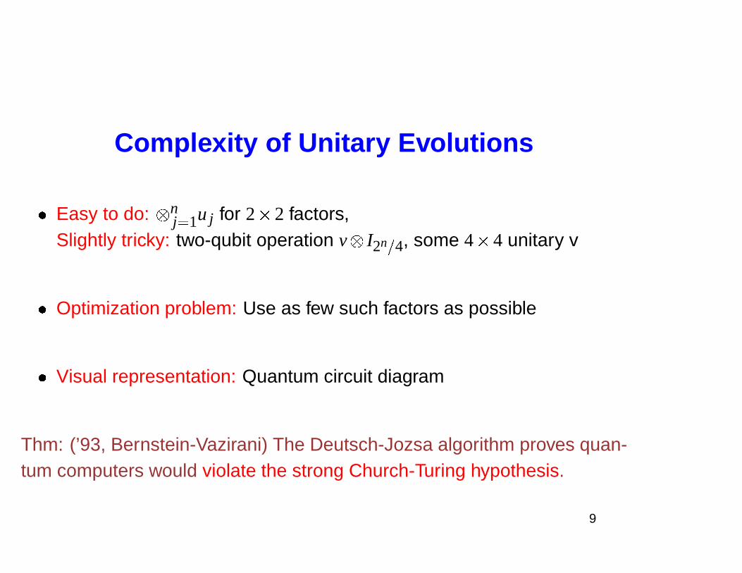
Complexity of Unitary Evolutions
� Easy to do: nj� 1u j for 2 � 2 factors,
Slightly tricky: two-qubit operation v I2n
�
4, some 4 � 4 unitary v
� Optimization problem: Use as few such factors as possible
� Visual representation: Quantum circuit diagram
Thm: (’93, Bernstein-Vazirani) The Deutsch-Jozsa algorithm proves quan-tum computers would violate the strong Church-Turing hypothesis.
9
Complexity of Unitary Evolutions Cont.
U
u1 u4
v2
u7
�� u2
v1
u5
v3
u8
u3 u6 u9
_ _ _ _�
�
�
�
�
�
�
�
�
�
�
�
�
�
�
�
�
�
�
�
�
�
�
�
�
�
�
�
�
�
�
�
_ _ _ _
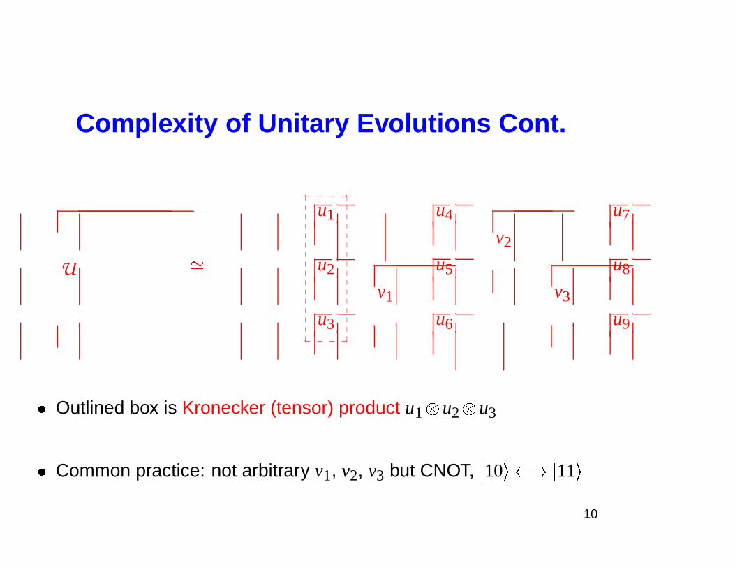
� Outlined box is Kronecker (tensor) product u1 u2 u3
� Common practice: not arbitrary v1, v2, v3 but CNOT, � 10 � � � � 11 �
10
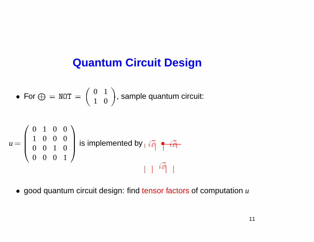
Quantum Circuit Design
� For � � � �� �
0 11 0
, sample quantum circuit:
u � ��
0 1 0 01 0 0 00 0 1 00 0 0 1
�� is implemented by 76540123 � 76540123
76540123
� good quantum circuit design: find tensor factors of computation u
11
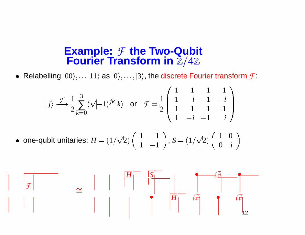
Example: F the Two-QubitFourier Transform in � � 4 �
� Relabelling � 00 ���� � � � 11 � as � 0 ���� � � � � 3 � , the discrete Fourier transform F :
� j �
F
� � 12
3
∑k� 0
� � 1 � jk � k � or F �
12
��
1 1 1 11 i � 1 � i1 � 1 1 � 11 � i � 1 i
��
� one-qubit unitaries: H � � 1 � 2 �1 11 � 1
, S � � 1 � 2 �
1 00 i
FH S � 76540123 �
��
� H 76540123 � 76540123
12
Outline
I. Introduction to Quantum CircuitsII. Two Qubit Circuits (CD)
III. Circuits for Diagonal UnitariesIV. Half CNOT per Entry (CSD)V. Differntial Topology & Lower Bounds
13
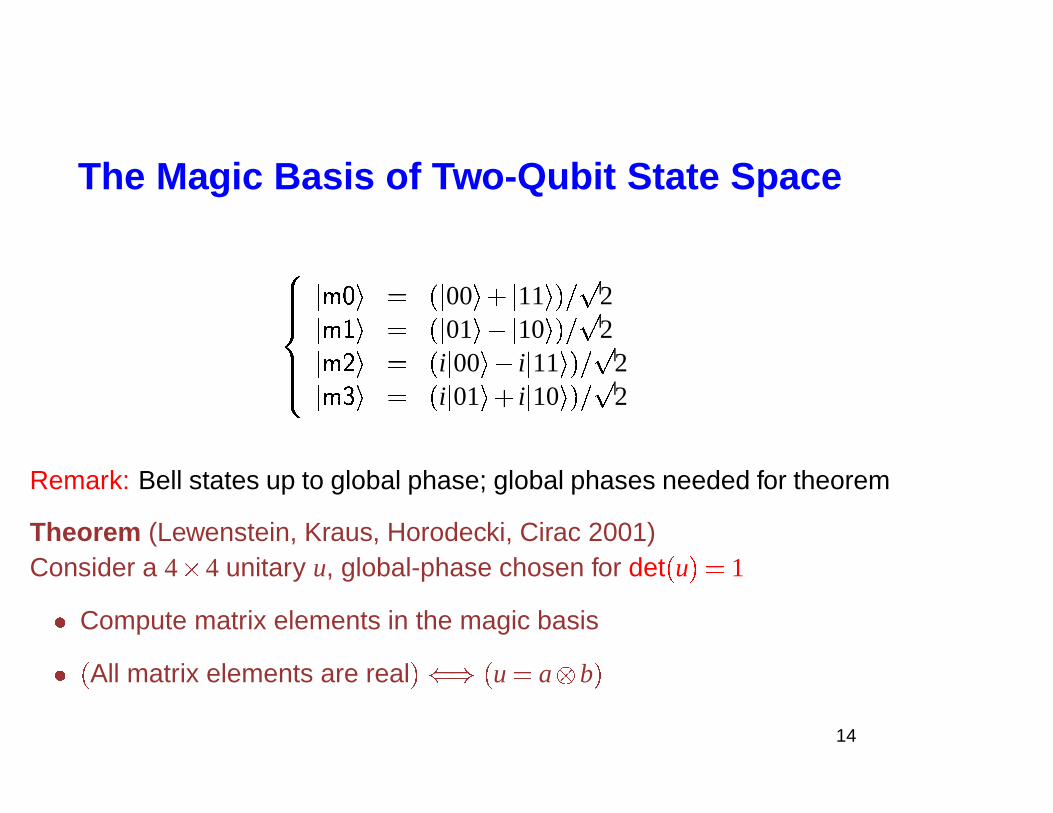
The Magic Basis of Two-Qubit State Space
� ���� ���
���� � � � � � 00 � � � 11 � � � 2
��� � � � � � 01 � � � 10 � � � 2��� � � � � i � 00 � � i � 11 � � � 2
��� � � � i � 01 � � i � 10 � � � 2
Remark: Bell states up to global phase; global phases needed for theorem
Theorem (Lewenstein, Kraus, Horodecki, Cirac 2001)Consider a 4 � 4 unitary u, global-phase chosen for det � u � � 1
� Compute matrix elements in the magic basis
� � All matrix elements are real �� � � u � a b �
14
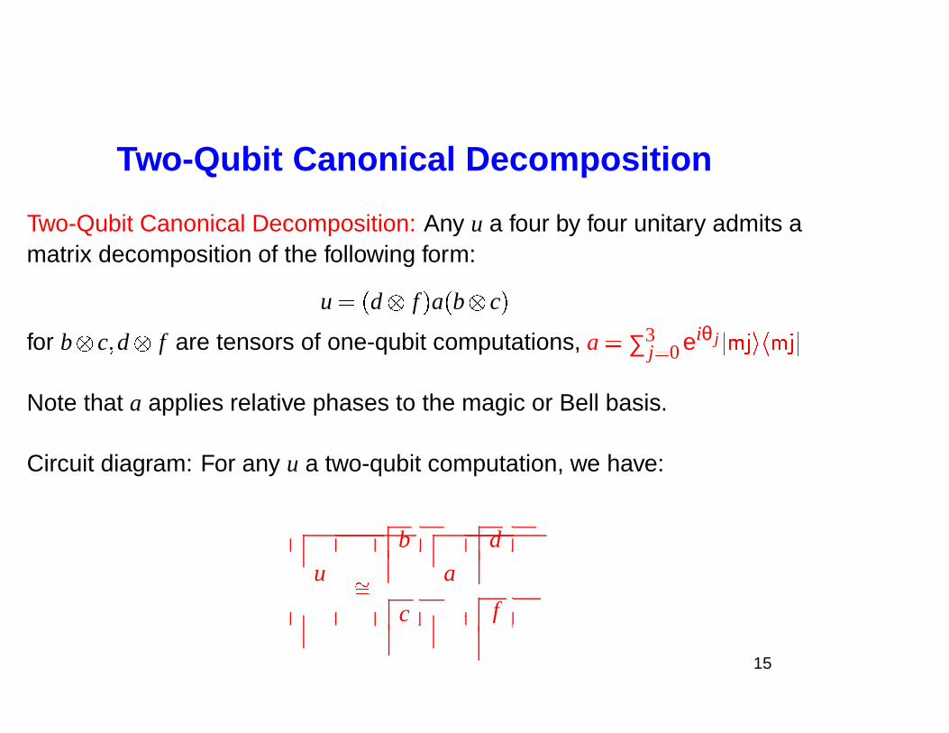
Two-Qubit Canonical Decomposition
Two-Qubit Canonical Decomposition: Any u a four by four unitary admits amatrix decomposition of the following form:
u � � d f � a � b c �
for b c� d f are tensors of one-qubit computations, a � ∑3j� 0 eiθ j ��� � � � � � �
Note that a applies relative phases to the magic or Bell basis.
Circuit diagram: For any u a two-qubit computation, we have:
u
b
a
d
��
c f
15
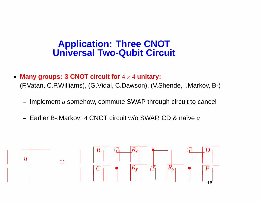
Application: Three CNOTUniversal Two-Qubit Circuit
� Many groups: 3 CNOT circuit for 4 � 4 unitary:(F.Vatan, C.P.Williams), (G.Vidal, C.Dawson), (V.Shende, I.Markov, B-)
– Implement a somehow, commute SWAP through circuit to cancel
– Earlier B-,Markov: 4 CNOT circuit w/o SWAP, CD & naıve a
uB 76540123 Rz � 76540123 D
��
C � Ry 76540123 Ry � F
16
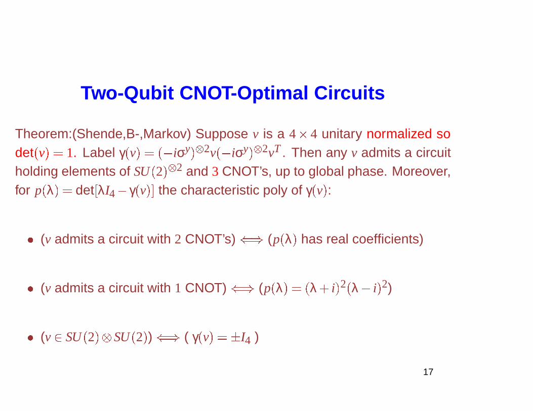
Two-Qubit CNOT-Optimal Circuits
Theorem:(Shende,B-,Markov) Suppose v is a 4 � 4 unitary normalized sodet � v � � 1. Label γ � v � � �� iσy ��� 2v �� iσy ��� 2vT . Then any v admits a circuitholding elements of SU � 2 � � 2 and 3 CNOT’s, up to global phase. Moreover,for p � λ � � det � λI4� γ � v �� the characteristic poly of γ � v � :
� (v admits a circuit with 2 CNOT’s) � (p � λ � has real coefficients)
� (v admits a circuit with 1 CNOT) � (p � λ � � � λ� i � 2 � λ� i � 2)
� (v� SU � 2 � SU � 2 � ) � ( γ � v � � � I4 )
17
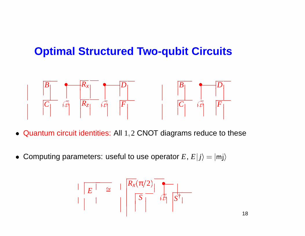
Optimal Structured Two-qubit Circuits
B � Rx � D B � D
C 76540123 Rz 76540123 F C 76540123 F
� Quantum circuit identities: All 1� 2 CNOT diagrams reduce to these
� Computing parameters: useful to use operator E, E � j � � ��� � �
ERx � π � 2 � �
��
S 76540123 S†
18
Outline
I. Introduction to Quantum CircuitsII. Two Qubit Circuits (CD)
III. Circuits for Diagonal UnitariesIV. Half CNOT per Entry (CSD)V. Differntial Topology & Lower Bounds
19
Relative Phase Group
� Easiest concievable n-qubit circuit question: How to build circuits for
A � 2n � �
2n � 1
∑j� 0
eiθ j � j � � j � ; θ j� � ?
� A � 2n � commutative � � vector group
– log : A � 2n � � � � 2n � carries matrix multiplication to vector sum
– Strategy: build decompositions from vector space decompositions
– Subspaces encoded by characters, i.e. continuous group mapsχ : A � 2n � � � eit
�
20
Characters Detecting Tensors
� ker logχ is a subspace of � � 2n �
� Subspaces � j ker logχ j exponentiate to closed subgroups
Example: a � ∑2n � 1j� 0 z j � j � � j �� A � 2n � has a � a Rz � α � if and only if
z0 � z1 � z2 � z3 � � � � � z2n � 2 � z2n � 1
So a factors on the bottom line if and only if a� �
2n� 1 � 1j� 0 ker χ j
for χ j � a � � z2 jz2 j � 2 � � z2 j � 1z2 j � 3 � .
21
Circuits for A
�
2n
�
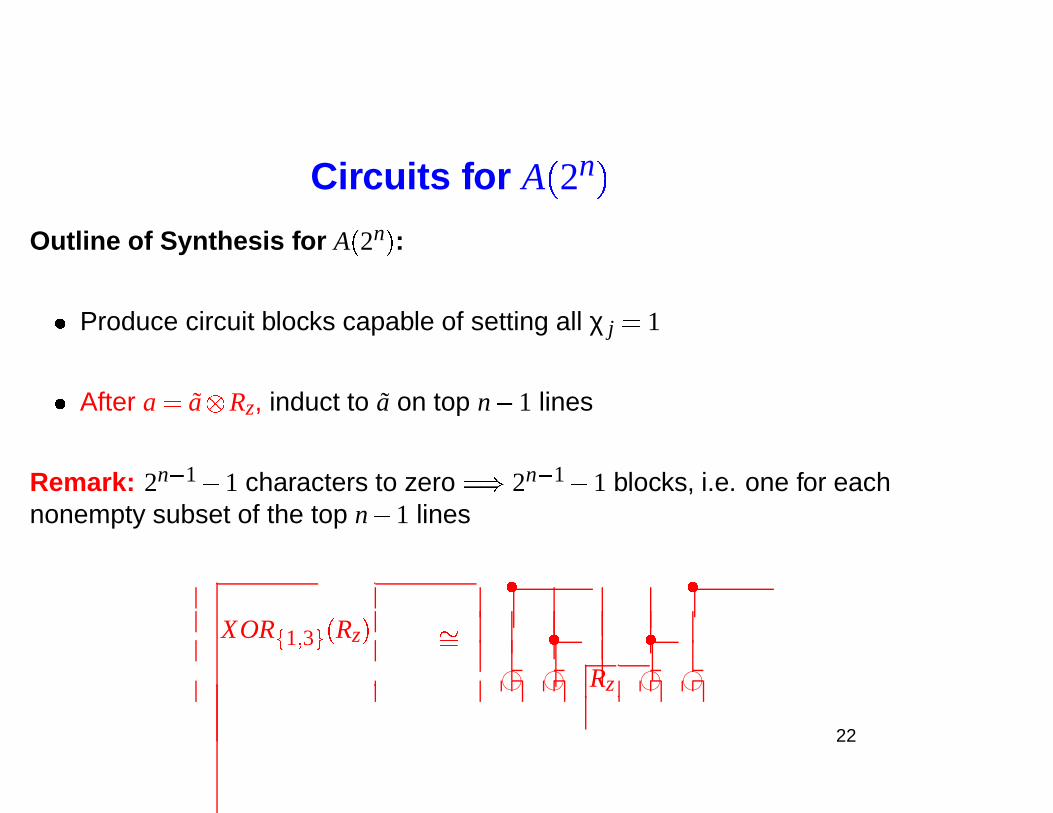
Outline of Synthesis for A � 2n � :
� Produce circuit blocks capable of setting all χ j � 1
� After a � a Rz, induct to a on top n� 1 lines
Remark: 2n � 1� 1 characters to zero � � 2n � 1� 1 blocks, i.e. one for eachnonempty subset of the top n� 1 lines
XOR
�
1 � 3 �
� Rz �
� �
�� � �
76540123 76540123 Rz 76540123 76540123
22
Circuits for A
�
2n
�
, Cont.
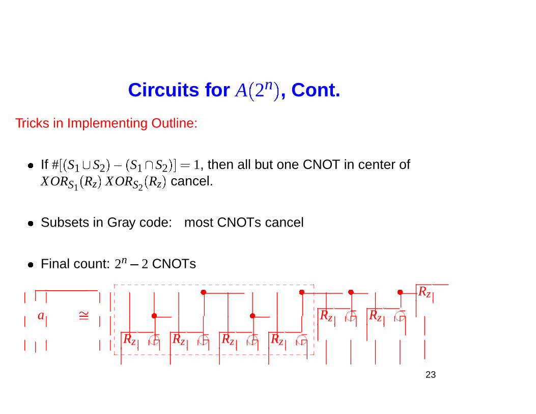
Tricks in Implementing Outline:
� If # � � S1 � S2 ��� � S1� S2 �� � 1, then all but one CNOT in center ofXORS1 � Rz � XORS2 � Rz � cancel.
� Subsets in Gray code: most CNOTs cancel
� Final count: 2n� 2 CNOTs
a
� � � � Rz
�� � � Rz 76540123 Rz 76540123
Rz 76540123 Rz 76540123 Rz 76540123 Rz 76540123
_ _ _ _ _ _ _ _ _ _ _ _ _ _ _ _ _ _ _ _ _ _ _ _ _ _ _ _ _ _�
�
�
�
�
�
�
�
�
�
�
�
�
�
�
�
�
�
�
�
_ _ _ _ _ _ _ _ _ _ _ _ _ _ _ _ _ _ _ _ _ _ _ _ _ _ _ _ _ _
23
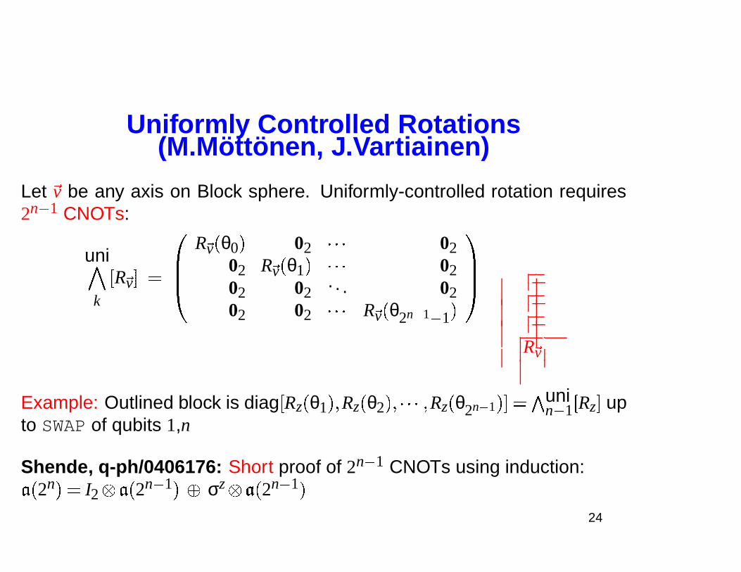
Uniformly Controlled Rotations(M.Mottonen, J.Vartiainen)
Let �v be any axis on Block sphere. Uniformly-controlled rotation requires2n � 1 CNOTs:
uni
k
�R �v� � ��
R �v � θ0 � 02 � � � 0202 R �v � θ1 � � � � 0202 02
. . . 0202 02 � � � R �v � θ2n� 1 � 1 �
��
R �v
Example: Outlined block is diag �Rz � θ1 � � Rz � θ2 �� � � � � Rz � θ2n� 1 �� � �
unin � 1 �Rz� up
to SWAP of qubits 1,n
Shende, q-ph/0406176: Short proof of 2n � 1 CNOTs using induction:
� � 2n � � I2 � � 2n � 1 � � σz � � 2n � 1 �
24
Outline
I. Introduction to Quantum CircuitsII. Two Qubit Circuits (CD)
III. Circuits for Diagonal UnitariesIV. Half CNOT per Entry (CSD)V. Differntial Topology & Lower Bounds
25
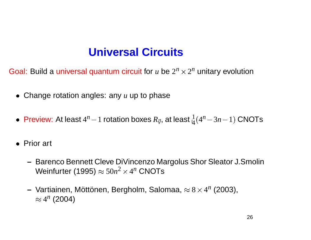
Universal Circuits
Goal: Build a universal quantum circuit for u be 2n
� 2n unitary evolution
� Change rotation angles: any u up to phase
� Preview: At least 4n� 1 rotation boxes R �v, at least 14 � 4n� 3n� 1 � CNOTs
� Prior art
– Barenco Bennett Cleve DiVincenzo Margolus Shor Sleator J.SmolinWeinfurter (1995) � 50n2
� 4n CNOTs
– Vartiainen, Mottonen, Bergholm, Salomaa, � 8 � 4n (2003),
� 4n (2004)
26
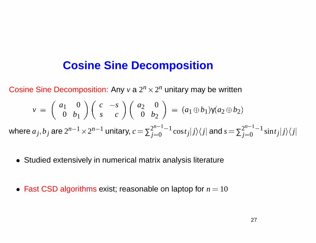
Cosine Sine Decomposition
Cosine Sine Decomposition: Any v a 2n
� 2n unitary may be written
v �
a1 00 b1
c � ss c
a2 00 b2
� � a1� b1 � γ � a2� b2 �
where a j� b j are 2n � 1
� 2n � 1 unitary, c � ∑2n� 1 � 1j� 0 cos t j � j � � j � and s � ∑2n� 1 � 1
j� 0 sin t j � j � � j �
� Studied extensively in numerical matrix analysis literature
� Fast CSD algorithms exist; reasonable on laptop for n � 10
27
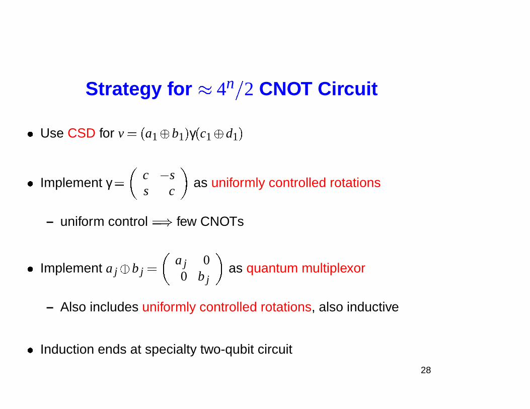
Strategy for � 4n
� 2 CNOT Circuit
� Use CSD for v � � a1� b1 � γ � c1� d1 �
� Implement γ �
c � ss c
as uniformly controlled rotations
– uniform control � � few CNOTs
� Implement a j� b j �
a j 00 b j
as quantum multiplexor
– Also includes uniformly controlled rotations, also inductive
� Induction ends at specialty two-qubit circuit
28
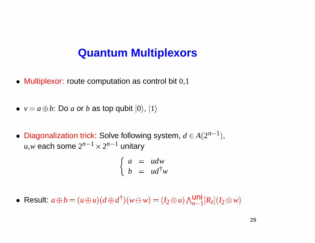
Quantum Multiplexors
� Multiplexor: route computation as control bit 0,1
� v � a� b: Do a or b as top qubit � 0 � , � 1 �
� Diagonalization trick: Solve following system, d� A � 2n � 1 � ,u,w each some 2n � 1
� 2n � 1 unitary
a � udwb � ud†w
� Result: a� b � � u� u � � d� d† � � w� w � � � I2 u � �
unin � 1 �Rz� � I2 w �
29
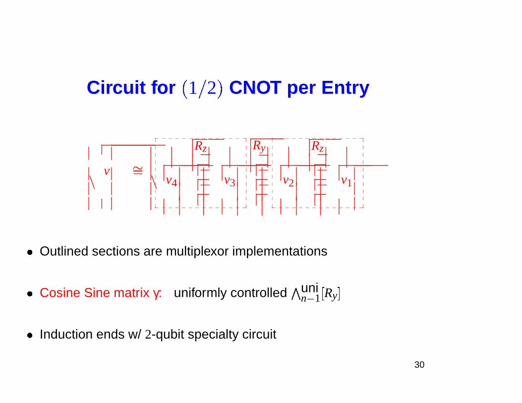
Circuit for
�
1 � 2
�
CNOT per Entry
v
Rz Ry Rz
v4 v3 v2 v1�
��
�
_ _ _ _ _ _ _ _ _ _ _ _ _ _�
�
�
�
�
�
�
�
�
�
�
�
�
�
�
�
�
�
�
�
_ _ _ _ _ _ _ _ _ _ _ _ _ _
_ _ _ _ _ _ _ _ _ _ _ _ _ _�
�
�
�
�
�
�
�
�
�
�
�
�
�
�
�
�
�
�
�
_ _ _ _ _ _ _ _ _ _ _ _ _ _
� Outlined sections are multiplexor implementations
� Cosine Sine matrix γ: uniformly controlled �unin � 1 �Ry�
� Induction ends w/ 2-qubit specialty circuit
30
Circuit Errata
� Lower bound � � (can be improved by no more than factor of 2)
� 21 CNOTs in 3 qubits: currently best known
� � 50% CNOTs on bottom two lines
– Adapts to spin-chain architecture with � 4� 5 � � 4n CNOTs
– Quantum charge couple device (QCCD) with 3 or 4 qubit chamber?
31
Outline
I. Introduction to Quantum CircuitsII. Two Qubit Circuits (CD)
III. Circuits for Diagonal UnitariesIV. Half CNOT per Entry (CSD)V. Differntial Topology & Lower Bounds
32
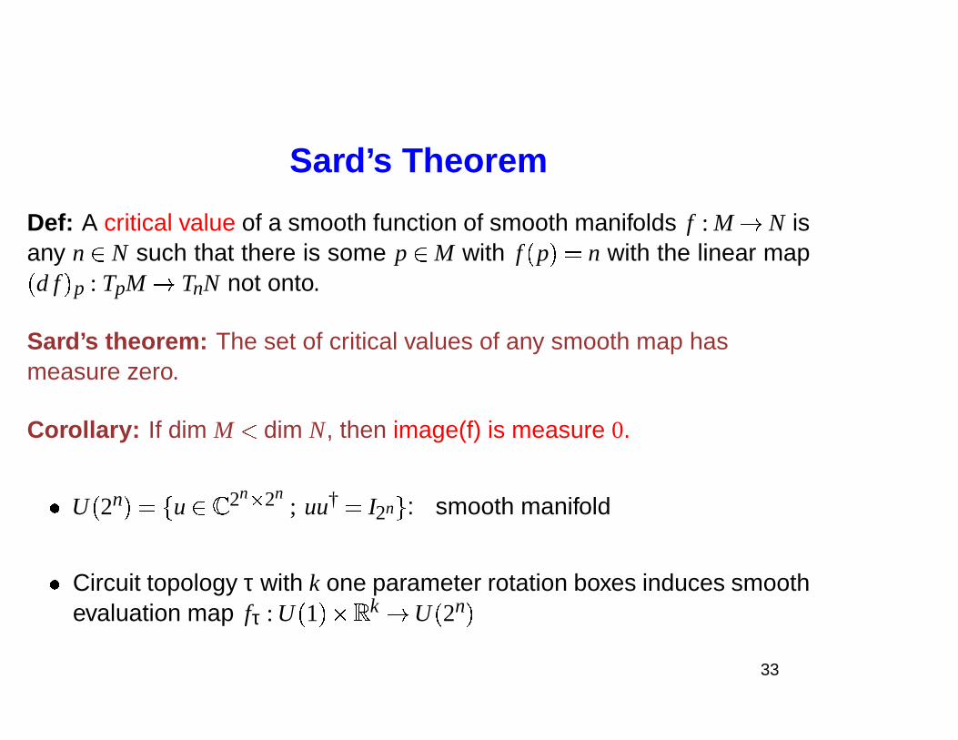
Sard’s Theorem
Def: A critical value of a smooth function of smooth manifolds f : M � N isany n� N such that there is some p� M with f � p � � n with the linear map
� d f � p : TpM � TnN not onto.
Sard’s theorem: The set of critical values of any smooth map hasmeasure zero.
Corollary: If dim M � dim N, then image(f) is measure 0.
� U � 2n � �
� u� � 2n � 2n; uu† � I2n � : smooth manifold
� Circuit topology τ with k one parameter rotation boxes induces smoothevaluation map fτ : U � 1 � � �
k � U � 2n �
33
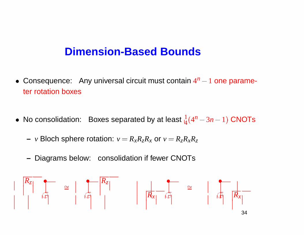
Dimension-Based Bounds
� Consequence: Any universal circuit must contain 4n� 1 one parame-ter rotation boxes
� No consolidation: Boxes separated by at least 14 � 4n� 3n� 1 � CNOTs
– v Bloch sphere rotation: v � RxRzRx or v � RzRxRz
– Diagrams below: consolidation if fewer CNOTs
Rz � � Rz � �
76540123
��
76540123 Rx 76540123
��76540123 Rx
34
On-going Work
� Subgroups H of unitary group U � 2n �
– More structure, smaller circuits?
– Symmetries encoded within subgroups H
– Native gate libraries?
� Special purpose circuits
– Backwards: quantum circuits for doing numerical linear algebra?
– Entanglement dynamics and circuit structure
35
http://www.arxiv.org Coordinates
� Two-qubits: q-ph/0308045
� Diagonal circuits: q-ph/0303039
� Uniform control: q-ph/0404089
� � 1 � 2 � CNOT/entry: q-ph/0406176
� Circuit diagrams by Qcircuit.tex: q-ph/0406003
36