Embed Size (px)
Citation preview

1
MATRIX MICROPROCESSOR
CONTROL PANEL
Installation – Operation – Maintenance Manual
9-7-10
REV-1.75

2
INDEX
• Introduction………………………………………………………………………. 3
• Liquid Recirculator Operation………………………………………………….. 4 o Level Control…………………………………………………………….. 4
� Level Probe………………………………………………………. 4 � Liquid Feed Solenoids………………………………………….. 5 � Liquid Feed Motorized Valves…………………………………. 7 � Float Switches………………………………..………………….. 10
o Pump Control…………………………………………………………….. 11 � Two Pump………………………………………………………… 12 � Three Pump………………………………. …………………….. 13 � Pump Bypass Control……………………………………. …….. 14 � Pump Cavitation Control………………………………………… 14 � Spiral Freezer Start-up Mode…………………………………… 15
• Configuration & Options…………………………………………………………. 16 o I/O descriptions…………………………………………………………… 17
• Keypad…………………………………………………………………………….. 22
• Display Screens………………………………………………………………….. 23
• Set-point Table…………………………………………………………………… 65
• Jumper Selection Tables………………………………………………………...68
• Specifications…………………………………………………………………….. 69
• Panel Layout & Drawings……………………………………………………….. 74

3
INTRODUCTION
The RVS Matrix Microprocessor Control utilizes the latest in microprocessor technology to provide a total control solution for Refrigeration Recirculator Vessels. RVS is the first in the industry to integrate all of the recirculator functions into a single microprocessor control panel. Standard features include, proportional liquid level control, automatic pump control, pump and pump motor protection, data collection and communications. Matrix is packaged into a UL/cUL listed NEMA 4 panel and is available with or without integrated motor starters. Matrix is easy to set-up and easy to use. The large graphic display and simple keypad combine to provide an easy to navigate, operator-friendly interface. Set-point entry and calibration require a few simple keystrokes. Matrix easily interfaces with most system controls through a globally standard MODBUS communications protocol. Factory packaging assures a completely tested and functional unit, ready-to-go, without expensive field wiring and complicated PLC logic.
Matrix is a lower installed cost solution! Liquid recirculators are used in industrial refrigeration systems to supply refrigerant to the evaporators in the product freezers. A Liquid Recirculator consists of the following components:
• Vessel
• Two or three pumps
• Pump motors
• Pump motor starters
• Liquid level sensor or liquid level floats
• Liquid make-up solenoids or motorized valves
• Control panel There are two basic control functions that need to be performed for proper operation. Liquid level control and pump control. This document will describe, in detail, the operation of a microprocessor controlled Liquid Recirculator package.
4
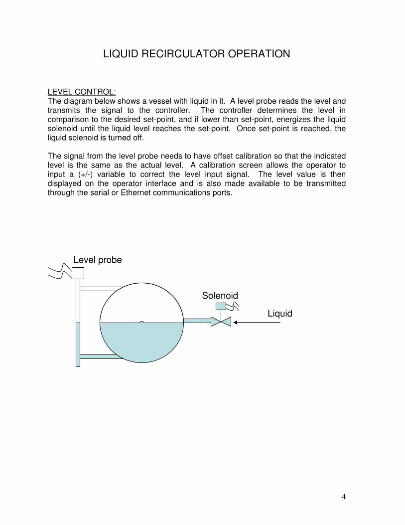
LIQUID RECIRCULATOR OPERATION LEVEL CONTROL: The diagram below shows a vessel with liquid in it. A level probe reads the level and transmits the signal to the controller. The controller determines the level in comparison to the desired set-point, and if lower than set-point, energizes the liquid solenoid until the liquid level reaches the set-point. Once set-point is reached, the liquid solenoid is turned off. The signal from the level probe needs to have offset calibration so that the indicated level is the same as the actual level. A calibration screen allows the operator to input a (+/-) variable to correct the level input signal. The level value is then displayed on the operator interface and is also made available to be transmitted through the serial or Ethernet communications ports.
Level probe
Liquid
Solenoid

5
The control algorithm is a simple servo feedback loop incorporating Proportional control as shown in the following diagram.
The analog value is read from the level probe and compared to the set-point entered by the operator. If the level is at set-point or higher, the output remains off and the solenoid is closed. If the level drops below set-point, the output is turned on and the solenoid is opened. The output remains open until the level reached the set-point. A small dead-band is placed at set-point (1%) so that the solenoid cannot chatter. An example would be if the operator set the desired level at 40%. The solenoid would close at 40% and open at 39%. If there is a “High Level Alarm” or “High Level Shutdown”, the liquid feed solenoid is de-energized. The liquid feed solenoid stays closed after a “High Level Alarm” or “High Level Shutdown” until the level drops below the operating level. Once below the operating level, the liquid feed solenoid is re-energized under control of the liquid level control set-point. When the “Stop key is pressed, the liquid feed solenoid is closed and remains closed until the “Enable” key is pressed and the level is below set-point. When there is a “Low Level Alarm” or “Low Level Shutdown”, the liquid feed solenoid continues to operate to get the vessel level back to normal operating level. The liquid feed solenoid can be manually operated from the “Mode Screen” if the proper system password is entered. This should only be done by a qualified person as the vessel can be overfilled. The controller will over ride the “Manual On” selection once the level reaches the “High Level Alarm” set-point. At this point, the solenoid is shut off. Once the level drops below the “High Level Alarm” set-point, the solenoid will be re-energized. Manual liquid feed for solenoids can be done in both “Enabled” and “Off” modes.
Controller
Level probe
Liquid make-up Solenoid
Analog in Digital out

6
Dual liquid make-up solenoids can be employed to optimize for full load and part load conditions. The two solenoids can be the same size or one larger than the other. The software would be configured so that the solenoids would be energized in a two-stage configuration. Using the previous example, where the set-point is at 40%, solenoid #1 would open when the level drops to 39%. Solenoid #2 would open when the level dropped to 34%. At this point, both solenoids are open and feeding liquid to the vessel. When the level begins to rise, the #2 solenoid would shut off at 35% and the #1 solenoid would shut off at 40%. If there is a “High Level Alarm” or “High Level Shutdown”, the liquid feed solenoids are de-energized. The liquid feed solenoids stay closed after a “High Level Alarm” or “High Level Shutdown” until the level drops below the operating level. Once below the operating level, the liquid feed solenoids are re-energized under control of the liquid level control set-point. When the “Stop key is pressed, the liquid feed solenoids are closed and remains closed until the “Enable” key is pressed and the level is below set-point. When there is a “Low Level Alarm” or “Low Level Shutdown”, the liquid feed solenoids continue to operate to get the vessel level back to normal operating level. The liquid feed solenoids can be manually operated from the “Mode Screen” if the proper system password is entered. This should only be done by a qualified person as the vessel can be overfilled. The controller will over ride the “Manual On” selection once the level reaches the “High Level Alarm” set-point. At this point, the solenoid is shut off. Once the level drops below the “High Level Alarm” set-point, the solenoids will be re-energized. Manual liquid feed for solenoids can be done in both “Enabled” and “Off” modes.
Level probe
Liquid
2 Solenoids

7
MOTORIZD LIQUID FEED VALVES Variable motorized valves can be substituted for the liquid make-up solenoids. The variable valve has the advantage of feeding liquid at full flow or part load. Motorized valves eliminate the liquid hammer effect from solenoids. True P-I-D control can be used with the motorized valve where only the proportional part of the P-I-D control can be used with the solenoid. The microprocessor controller outputs a 4-20mA signal to drive the valve.
The analog value is read from the level probe and compared to the set-point entered by the operator. The software is configured so that the valve opens proportional to the difference in level from set-point. An example would be if the operator set the desired level set-point at 40%, the valve closed set-point at 0% difference and fully open set-point at 10% difference. If the level is at set-point or higher, the analog output remains at 4 mA which drives the motorized valve closed. If the level drops below set-point, each 1% drop, opens the valve 10%. When the vessel level drops to 30%, the valve is at 20 mA and is fully open.
Analog out Analog in
Controller
Level probe
Liquid make-up motorized valve P-I-D

8
A solenoid should be included with the motorized valve. The reason for the solenoid is that it acts as a back-up safety device in case the motorized valve sticks open or fails operate. The controller will close the solenoid when the level reaches the “Level Control” set-point + the “Solenoid Off Diff” set-point, regardless of the motorized valve position. In addition, some valves may not close during a power failure, allowing liquid to continue to flow into the vessel, possibly over filling it. The solenoid assures liquid shutoff. If there is a “High Level Alarm” or “High Level Shutdown”, the motorized valve is driven closed. The liquid feed solenoid stays closed after the level reaches the “Level Control” set-point + the “Solenoid Off Diff” set-point, until the level drops below the operating level. Once below the operating level, the liquid feed solenoid is re-energized. The motorized valve then takes over control of the liquid level. When the “Stop” key is pressed, the liquid feed solenoid is closed and remains closed until the “Enable” key is pressed. The motorized valve is also driven closed when the “Stop” key is pressed and remains closed until the “Enable” key is pressed. When there is a “Low Level Alarm” or “Low Level Shutdown”, the liquid feed solenoid and motorized valve continue to operate to get the vessel level back to normal operating level. The liquid feed motorized valve can be manually operated from the “Mode Screen” if the proper system password is entered. This should only be done by a qualified person as the vessel can be overfilled. The manual operation of the motorized valve will only work when the panel is enabled. The motorized valve is always driven closed in the “Off” mode. Once the
Level probe
Liquid
Motorized valve Solenoid

9
panel is enabled the operator can select the motorized valve opening manually on the mode screen. The controller will over ride the “Manual” selection once the level reaches the “Level Control” set-point + the “Solenoid Off Diff” set-point. At this point, the solenoid valve is de-energized. The controller will also over ride the “Manual” selection once the level reaches the “High Level Alarm” set-point. At this point, the motorized valve is driven closed. Once the level drops below the operating set-point, the solenoid will be re-energized. The motorized valve will be held at 0% and the operator will have to reset the desired manual setting on the “Mode Screen”. If the “Stop key is pressed, the liquid solenoid will close and the motorized valve will be driven closed. Two motorized valves can be incorporated where they can be set up as a two stage system.
Operation is similar to the previous example, except that valve #1 operates from 0 to 10% deviation from set-point. Valve #2 would operate from 10% to 20% deviation from set-point.
Level probe
Liquid
motorized valves

10
LEVEL FLOAT SWITCHES In some situations, the controller will be fitted to older systems that may not be able to have an analog level probe fitted to it. In that case, the existing float valves will have to be utilized to measure the level in the vessel.
Single or dual liquid feed solenoid valves can be employed with this configuration, but variable motorized valves cannot be used. Multiple liquid solenoid operation is the same as previous descriptions, so we will concentrate on the operation of the float tree.
The mechanical floats are in fixed positions and cannot be moved. Therefore the level control set-points are fixed. The controller accepts up to four level floats as input devices. The top float is the high level system shutdown float. The bottom is
Digital out Digital in
Controller
Liquid make-up solenoid Level floats
Liquid
Liquid solenoids
Level floats

11
the low level pump shutdown float. The two middle floats control the two liquid feed valves. When the level drops and the float switch contacts open, the input to the microprocessor is disabled. The microprocessor delays the output to the liquid solenoid by an operator settable time delay to prevent solenoid chatter. After the delay, the solenoid is energized. When the level rises and the float switch contacts close, the input to the microprocessor is enabled. The microprocessor delays shutting off the solenoid by an operator settable time delay to prevent solenoid chatter. After the delay, the solenoid is de-energized. When float switches are employed, rather than an analog level probe, only two pumps can be controlled by the microprocessor panel. PUMP CONTROL The diagram below shows a refrigerant pump with:
• Pump oil level switch (Cornell pumps only)
• Pump bypass
• Pump run contacts
• Pump motor current
• Pump discharge pressure sensor
The operator can place the pumps in the following modes:
• Manual off
• Manual on
• Automatic
Inlet (from vessel)
Pump
Pump bypass solenoid
Pump discharge pressure sensor
Outlet (to freezer)
Pump oil level
Pump run contacts
A

12
TWO PUMP OPERATION In a typical two pump operation, one pump will run and one will be in the stand-by mode. The operator can select which pump will run and which pump will be in the stand-by mode. The operator can also select that there is no standby pump by placing the second pump in the off position. The pump is energized when the operator presses the “Enable” key or a communications “enable” command is received and the “Remote enable” input is energized. The “remote enable” I/O input must always be at a logic one for the pumps to run. If the remote enable I/O input is low, the pumps will remain off but in the ready to run mode. Once the pump output is energized, the software will look for verification that the pump is running by looking at the pump running contacts which should be at a logic one within 5 seconds. If not, the pump output is turned off and a “Pump Auxiliary Shutdown” is generated. The software also looks at pump motor current and verifies that the motor current is above the minimum motor current set-point. If not, after a time delay the pump is shut down and a “Low Amps Shutdown” is generated. If the pump fails due to cavitation, low differential pressure, low or high motor amps, the stand-by pump will be automatically started after the first pump is shut down. An alarm is issued due to the failure of the lead pump. If the standby pump also fails, the system is in a shutdown mode and requires operator intervention. If there is a “High Level Alarm” or “High Level Shutdown” the pumps will continue to operate. If it is a “High Level Alarm”, the pumps will continue to run after the alarm is cleared on the “Alarm Screen”. If it is a “High Level Shutdown” the pumps will shut down once the alarm is cleared, and the operator will have to press the “Enable” button to resume operation. If there is a “Low Level Alarm” or “Low Level Shutdown” the pumps will stop. If it is a “Low level Alarm”, the pumps will stop and stay off. The pump status will be indicated as “Hold-Off”. Once the vessel level reaches operating set-point, the pumps will start. If it is a “Low Level Shutdown”, the pumps will be held off. The operator will have to clear the alarm and press the “Enable’ button. The pumps can be manually operated from the “Mode Screen”. Manual pump control can be done in both “Enabled” and “Off” modes.
13
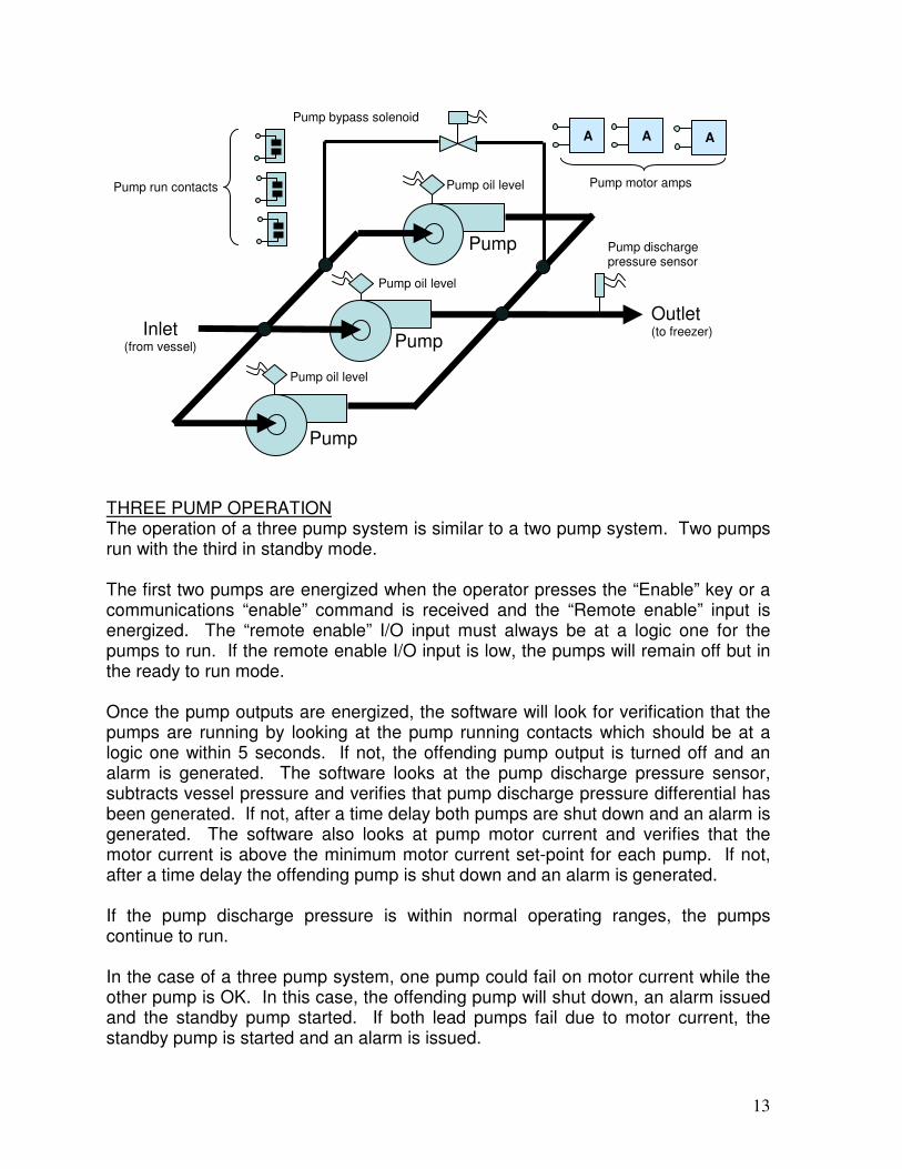
THREE PUMP OPERATION The operation of a three pump system is similar to a two pump system. Two pumps run with the third in standby mode. The first two pumps are energized when the operator presses the “Enable” key or a communications “enable” command is received and the “Remote enable” input is energized. The “remote enable” I/O input must always be at a logic one for the pumps to run. If the remote enable I/O input is low, the pumps will remain off but in the ready to run mode. Once the pump outputs are energized, the software will look for verification that the pumps are running by looking at the pump running contacts which should be at a logic one within 5 seconds. If not, the offending pump output is turned off and an alarm is generated. The software looks at the pump discharge pressure sensor, subtracts vessel pressure and verifies that pump discharge pressure differential has been generated. If not, after a time delay both pumps are shut down and an alarm is generated. The software also looks at pump motor current and verifies that the motor current is above the minimum motor current set-point for each pump. If not, after a time delay the offending pump is shut down and an alarm is generated. If the pump discharge pressure is within normal operating ranges, the pumps continue to run. In the case of a three pump system, one pump could fail on motor current while the other pump is OK. In this case, the offending pump will shut down, an alarm issued and the standby pump started. If both lead pumps fail due to motor current, the standby pump is started and an alarm is issued.
Inlet (from vessel) Pump
Pump bypass solenoid
Pump discharge pressure sensor
Outlet (to freezer)
Pump oil level
Pump run contacts
Pump
Pump
Pump oil level
Pump oil level
A A A
Pump motor amps

14
If the pumps fail due to cavitation or low differential pressure the stand-by pump will be automatically started after the two pumps are shut down, in a failure mode. An alarm is issued due to the failure of the lead pumps. If the standby pump also fails, the system is in a shutdown mode and requires operator intervention PUMP BYPASS CONTROL The pump bypass solenoid is normally closed when the pumps are not running or when the system is in a shutdown or off mode. The pump bypass solenoid remains closed when a pump (or pumps) are started and remains closed until the following conditions are met:
• Pump motor current drops below the “low amps bypass on set-point”. This action is taken when either pump’s motor current or both pump’s drops to this set-point.
• The pump bypass solenoid is closed when the pump(s) motor current rises above the “low amps bypass off set-point”
PUMP CAVITATION (two pumps) Pump cavitation is defined as a drop in pump differential pressure, while the pump(s) are running. If the pump begins to cavitate and the pump differential pressure drops below the low pump ∆P shutdown set-point for the time delay period, the pump is shut down. The pump will remain off for an operator settable time period. This time delay is determined by the “pump cavitation off time delay” period. If the pump cavitates six times in an hour or accumulates six minutes of cavitation time in an hour, the pump is failed due to cavitation and the standby pump is started.
Controller
Pump bypass solenoid Pump motor current
A

15
PUMP CAVITATION (three pumps) The logic is the same except that both pumps will be shutdown together and re-started together. If both pumps fail due to cavitation, the standby pump is started. START-UP MODE FOR SPIRAL FREEZERS When the pump recirculator is applied to spiral freezers, a start-up mode can be enabled by the operator. In this mode, the vessel level is reset to a higher level for an operator settable time period so that extra liquid is available for freezer fill-up. The operator has access to the following set-points for the start-up mode:
• Mode: Normal or start-up
• Vessel level start-up set-point which is set in % above normal liquid level set-points. An example would be if the vessel has two liquid feed valves with control points at 30% and 35% and the start-up set-point was at 10% (higher). In the normal mode, the level would be maintained at 30% and 35% for each liquid feed valve. When the start-up mode is selected, the liquid level set points would be reset to 40% and 45% for the start-up time period which is in minutes. The display screen would indicate that the system is in the start-up mode.
• Start-up mode time delay – This is the amount of time the vessel remains in the start-up mode before returning to the normal mode. 30 minutes would be typical.

16
CONFIGURATION & OPTIONS
I/O TABLE when using an Analog Probe for level input:
Standard Optional DI DO AI AO DI DO AI AO Pumps 2 2 1 1
• Motor current 2 1
• Oil level (Cornell pumps) 2 1
• Bypass solenoid 1
• Discharge pressure 1
Liquid feed solenoid 1 1 Liquid feed motorized valve 2 Level float input 1 Level probe input 1 Alarm horn 1 Remote enable/disable input 1 Remote reset input 1 Vessel pressure 1 Vessel temperature 1 4-20 mA level signal to system 1 Totals 6 5 5 3 3 2 2 0 DI DO AI AO
Total I/O (including options) 9 7 7 3

17
I/O TABLE when using Float Switches for level input:
Standard Optional DI DO AI AO DI DO AI AO Pumps 2 2
• Motor current 2
• Oil level (Cornell pumps) 2
• Bypass solenoid 1
• Discharge pressure 1
Liquid feed solenoid 1 1 Liquid feed motorized valve Level float input 4 Level probe input Alarm horn 1 Remote enable/disable input 1 Remote reset input 1 Vessel pressure 1 Vessel temperature 1 Totals 9 5 4 0 1 1 1 0 DI DO AI AO
Total I/O (including options) 10 6 5 0
I/O DESCRIPTIONS DIGITAL INPUTS (DI):
• Pump – feedback from the pump motor starter that the pump is energized. When the input is a logic one, the pump motor starter is on. When the input is logic zero, the pump motor starter is off. One digital input is provided for each pump. The standard system has two pumps. A third pump can be added on systems using an analog level probe as means of measuring vessel level. If float switches are used to measure level, only two pumps can be operated by the control. The third pump can also be configured as a liquid transfer device in the software.
• Oil level (Cornell pumps) – Cornell pumps have oil level switches that change state when the oil level drops in the pump. When the input is a logic one, the pump is available to run. When the input is a logic zero, the pump has a failure and is not available to run. A logic zero on this input is an alarm condition. Each pump has its own oil level switch. Hansen, Buffalo and Teikoku pumps do not have this feature.
• Level float(s) input – For systems with an analog level probe, one digital input is available to connect the mechanical “high level shutdown float” to the controller. A logic one allows the system to operate normally. A logic zero

18
indicates a high liquid level in the vessel which causes the following actions to be taken:
o Continue to run the liquid pump(s) or start the liquid pump(s) if off and available to run.
o Issue a “High level” alarm. o Turn on the liquid transfer device, if one is included with the system.
For systems with mechanical floats to measure vessel level, three additional float level inputs are available. The level of the vessel can be determined approximately by placing (up to three) mechanical float switches vertically along the vessel. When each succeeding level float, from the bottom to the top changes from a logic zero to a logic one, the liquid level in the vessel is at that float position or above it. Float inputs at logic zero are above the liquid level in the vessel. Float inputs at a logic one are equal to or below the liquid level in the vessel. The software that controls liquid level in the vessel uses these inputs to determine the control of the liquid feed solenoid(s).
• Remote enable/disable – This input must be energized in order for the system to run. When the input is a logic zero, the controller is in the standby mode. Plant system controls can utilize this input to control the operation of the recirculator package.
• Remote reset input – This input is intended for a pushbutton action type device. When the input is a logic zero, the controller can operate. When the input is a logic one, the program is held in reset. When the input returns to a logic zero, the controller can operate.
DIGITAL OUTPUTS (DO):
• Pumps – when the software determines that a pump should be turned on, the digital output is set to a logic one. A logic zero turns the pump off. The software assures that an output cannot toggle any faster than 20 second intervals to protect the pump motor. One digital output is provided for each pump. The standard system has two pumps. A third pump can be added on systems using an analog level probe as means of measuring vessel level. If float switches are used to measure level, only two pumps can be operated by the control. The third pump can also be configured as a liquid transfer device in the software.
• Pump bypass – The pump bypass output energizes a solenoid that essentially connects the pump outlet to the pump inlet, which establishes the minimum flow required by the pumps for proper operation. A logic one on the output opens the solenoid. A logic zero on the output closes the solenoid.
o The pump bypass solenoid is always closed when no pumps are running.
o The pump bypass solenoid remains closed when one or more pumps are running and the motor current(s) are above the “Low amps bypass off” set-point. The output is set to a logic zero which closes the solenoid.

19
o The pump bypass solenoid is opened when one or more pumps motor current drops below the “Low amps bypass on” set-point. The output is set to a logic one which opens the solenoid.
o The pump bypass solenoid remains open until all running pump’s motor amps rise above the “Low amps bypass off ” set-point, where the bypass solenoid is then closed.
• Liquid feed – The vessel is replenished with liquid from liquid feed valve(s). After reading the level in the vessel, the software could determine that the liquid level in the vessel is low and needs to add liquid. A logic one on the liquid feed output, opens a solenoid, allowing liquid to flow into the vessel. A logic zero on the output closes the solenoid and stops the liquid flow. Once the liquid level in the vessel reaches the desired point, the liquid feed is turned off. The software assures that an output cannot toggle any faster than 5 second intervals to protect the solenoid. A second liquid feed solenoid can be employed where the two liquid feed solenoids act as a two-stage device. The first liquid feed valve operates as previously described. The second liquid feed valve is energized when the liquid level reaches a point lower than the first liquid feed valves feed set-point. With both valves energized, the vessel can be filled rapidly. Once the level reached the first feed valves lower set-point, the second feed valve is turned off.
• Alarm horn - Whenever an alarm condition is detected by the software, the alarm output is set to a logic zero. During normal operation, the alarm output is set to a logic one.
ANALOG INPUTS (AI):
• Motor current – The microprocessor control reads one leg of the three phase pump motor current with a current transformer (CT). The microprocessor uses the motor current reading to protect the pump motor and control the pump bypass solenoid. Pump motor amps are displayed on the main screen and the data screen. Set-points related to motor current are:
o Motor FLA o High motor amps alarm – after a time delay, a high motor amps alarm
is issued. o High motor amps shutdown – after a time delay, the motor is turned
off. o Low amps bypass on – If any pumps motor current drops below this
set-point, after a time delay the pump bypass solenoid is opened. o Low amps bypass off – If all of the running pumps motor currents are
above this set-point, after a time delay the pump bypass is closed. o Motor amps minimum (zero amps means the motor is not running) –
When a motor is started, the software looks for the motor auxiliary contact to confirm the motor starter is energized. The software also looks to see if a minimum motor current is generated which confirms the pump is running.
• Pump discharge pressure – The pumping pressure of the pump(s) are read by a pump discharge pressure transducer that outputs a 1-5V signal. The
20
pressure transducer range is 0-200 PSI absolute (-14.7 to 185.3 PSIG) Pump discharge pressure is indicated on the operator screen and is also available to be transmitted from the communications port. The vessel pressure is subtracted from the pump discharge pressure to get pump differential pressure. Pump differential pressure is displayed and made available to the communications port(s). Set-points related to pump discharge and pump differential pressure are:
o Low pump differential pressure, “pump cavitation” set-point –If the pump (s) begin to cavitate and the pump differential pressure drops below the low pump ∆P shutdown set-point for the time delay period, the pump(s) are shut down. The pumps will remain off for an operator settable time period. This time delay is determined by the “pump cavitation off time delay” period. If the pump cavitates six times in an hour or accumulates six minutes of cavitation time in an hour, the pump is failed due to cavitation and the standby pump is started.
• Level probe input – Rather than using level floats to determine the liquid level in a vessel, an analog level probe is employed to provide continuous liquid level input to the controller. The level range is from 0% to 100%. The analog input signal is a 4-20mA signal. The software determines the desired level in the vessel by placing set-points on the level column entered by the operator. Set-points related to level probe are:
o High level shutdown o High level alarm o Enable liquid transfer device o Disable liquid transfer device o Level control #1 o Level control #2 o Low level alarm o Low level shutdown
When the analog level probe is used, level float switch inputs cannot be used. Only one float switch input is available, which is the high level shutdown input.
• Vessel pressure – The pressure is measured inside the vessel with a pressure transducer that outputs a 1-5V signal. The pressure transducer range is 0-200 PSI absolute (-14.7 to 185.3 PSIG). Vessel pressure is indicated on the operator screen and is also available to be transmitted from the communications port. Vessel pressure is subtracted from pump discharge pressure to get pump differential pressure.
• Vessel temperature - The temperature is measured inside the vessel with a temperature probe that outputs a I uA/ºK signal. The temperature probe range is scaled from -459ºF to + 441ºF temperature range. Vessel temperature is indicated on the operator screen and is also available to be transmitted from the communications port.

21
ANALOG OUTPUTS (AO):
• Liquid feed – Rather than using solenoids to control liquid feed to the vessel, a continuously variable, motorized valve can be employed to provide continuous liquid make-up. The software reads the liquid level in the vessel and outputs a 4-20mA signal which drives the valve. The software executes a P-I-D loop algorithm to exactly control the valve. The valve’s position is indicated from 0% (closed) to 100% (open) Up to two valves can be employed to achieve two-stage filling in a course and fine mode.
• 4-20 mA level signal to system – Transmits the conditioned (calibrated) level signal to supervisory system controls.
KEYPAD The keypad provides a user interface to the control panel and is divided into three sections.
• Soft keys
• Direction & entry keys
• Enable/ Stop keys Soft Keys The five soft keys are located directly below the display and are defined by the software on the screen. Direction/Entry Keys The direction and entry keys allow the operator to navigate a screen by pressing the arrow key in the direction desired. The enter key finalizes a command to the controller. The up/down arrows increment/decrement the value in a set-point field, and the right/left arrows move to the next/previous set-point. The enter key must be pressed in order for the value change to be accepted. Stop/Reset Key The stop/reset key stops the operation of all devices which includes: pumps, liquid feed valves or solenoids and pump bypass valves or solenoids. If the system is shut down and in alarm, pressing the stop/reset key, resets the alarms and places the unit in the ready to operate mode. When on the alarm screen, pressing the stop/reset key clears all of the alarms without shutting down the pumps. Enable Key The enable key initiates operation of the system.

22
ENTER
ENABLE STOP
RESET

23
DISPLAY SCREENS The display is a 320 X 240 monochrome graphic LCD device. Operator displays are organized into categories as follows:
• Main
• Mode Screen o Startup Setup Screen
• Data Screen
• Alarm Screen o Alarm History Screen
� Freeze #1 Screen � Freeze #2 Screen
• Set-point Screen o Level Set-points #1
� Level Set-points #2 � Level Set-points #3
o Pump Set-points #1 � Pump Set-points #2
o Motor Set-points #1 � Motor Set-points #2 � Motor Set-points #3
o Miscellaneous Set-points � Date & Time
• Minute Trend Screen #1 o Minute Trend Screen #2 o Hour Trend Screen #1 o Hour Trend Screen #2
• Calibration Screen o Analog out #1 Calibration
� Analog out #2 Calibration � Analog out #3 Calibration
• System Set-up Screen o System Setup Screen #2
� Communications Setup o Service Screen
� Digital Input Status � Digital Output Status � Analog Input Status � Analog Output Status
o Screen Saver Setup o Security Code Setup o Initialize Set-points o Run Hours Screen
• Program Version Info
24
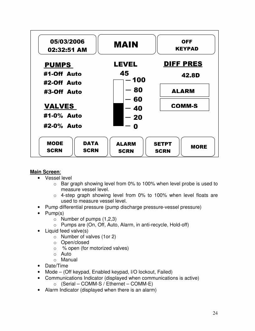
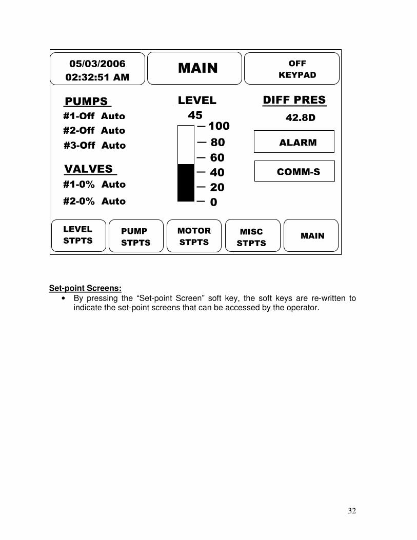
Main Screen:
• Vessel level o Bar graph showing level from 0% to 100% when level probe is used to
measure vessel level. o 4-step graph showing level from 0% to 100% when level floats are
used to measure vessel level.
• Pump differential pressure (pump discharge pressure-vessel pressure)
• Pump(s) o Number of pumps (1,2,3) o Pumps are (On, Off, Auto, Alarm, in anti-recycle, Hold-off)
• Liquid feed valve(s) o Number of valves (1or 2) o Open/closed o % open (for motorized valves) o Auto o Manual
• Date/Time
• Mode – (Off keypad, Enabled keypad, I/O lockout, Failed)
• Communications Indicator (displayed when communications is active) o (Serial – COMM-S / Ethernet – COMM-E)
• Alarm Indicator (displayed when there is an alarm)
#1-0% Auto
05/03/2006
02:32:51 AM MAIN
MODE
SCRN
DATA
SCRN
ALARM
SCRN
SETPT
SCRN MORE
PUMPS
#1-Off Auto
#2-Off Auto
#3-Off Auto
VALVES
#2-0% Auto
LEVEL
45
80
60
40
20
0
100
OFF
KEYPAD
DIFF PRES
42.8D
COMM-S
ALARM

25
Mode Screen: Micro Start Mode – Operator can select “Normal” or “Start-up”.
• Normal mode operates off of “Vessel Level #1 Set-point”
• Start-up mode is typically used for spiral freezers, but can be used for other applications as well. When the “Enable” button is pressed, the controller changes from the normal level to a higher level for a period of time. The higher level allows for extra liquid to fill the freezer and helps to prevent pump cavitation. After the “Startup Time” expires, the controller returns to the normal level setting. These settings are on the “Start-up Setup Screen”.
Pump Mode– Allows operator to select the operational mode for each pump.
• Pump #1 – On, Off, Auto
• Pump #2 – On, Off, Auto
• Pump #3 – On, Off, Auto Run hours – Displays run-time hours of each pump. Liquid Feed Mode – Allows the operator to select the operational mode of the solenoid or motorized liquid feed valves.
• (Solenoid) Liquid feed #1 – On, Off, Auto
• (Solenoid) Liquid feed #2 – On, Off, Auto
• (Motorized) Liquid feed #1 – Manual, Auto
• (Motorized) Liquid feed #1 – Manual, Auto
MAIN
MODE SCREEN
Micro Start Mode: Normal
Pump 1 Mode: Auto 22.9 Hrs
Pump 2 Mode: Auto 16.1 Hrs
Liq Feed 1 Mode: Manual 72%
Pump 3 Mode: Off 2.2 Hrs
STRTUP
SCRN
Liq Feed 1 Mode: Auto
Run Hours

26
Start-up Setup Screen:
• Level Control Set-point – Allows the operator to select a level (in %) above the normal operating level for startup.
• Startup Time – Operator adjustable startup time. The amount of time the level will be raised to the “Level Control Set-point Adjust” value. After the “Startup Time” has elapsed, the level is returned to the “Normal” level.
• Start-up mode is typically used for spiral freezers, but can be used for other applications as well. When the “Enable” button is pressed, the controller changes from the normal level to a higher level for a period of time. The higher level allows for extra liquid to fill the freezer and helps to prevent pump cavitation. After the “Startup Time” expires, the controller returns to the normal level setting. These settings are on the “Start-up Setup Screen”.
MAIN BACK
STARTUP SETUP SCREEN
Level Control Setpoint : 10%
Startup Time: 30 Min

27
Data Screen:
• Vessel Level %
• Pump Discharge Pressure PSI - Gauge
• Vessel Pressure PSI – Gauge or “Hg
• Pump Differential Pressure PSI - Differential
• Vessel Temperature ºF
• Pump #1: (On, Off, Auto, Alarm, in anti-recycle, hold-off)
• Pump #2: (On, Off, Auto, Alarm, in anti-recycle, hold-off)
• Pump #3: (On, Off, Auto, Alarm, in anti-recycle, hold-off)
• Pump #1: Motor Amps Amps
• Pump #2: Motor Amps Amps
• Pump #3: Motor amps Amps
• Liquid Feed Valve #1 (Open, Closed, %)
• Liquid Feed Valve #2 (Open, Closed, %)
• Bypass valve (Open, Closed) The “Scroll” indicator prompts the operator to press the up/down arrows to view additional data.
MAIN
DATA SCREEN
Vessel Level: 45.2%
Pump Disch Pressure: 75.8G
Vessel Pressure: 33.0G
Pump #1: On Auto
Pump #2: On Auto
Pump Diff. Pressure: 42.8D
Pump #3: Off Auto
Pump #1 Motor Amps 15.2A
Scroll

28
Alarm Screen:
• Displays up to 8 alarms along with time and date.
• In order to clear an alarm, the operator can clear individual alarms by pressing the clear alarm soft key on the alarm screen. An alternative would be to clear all of the alarms with a single key stroke by pressing the stop/reset key. While on the alarm screen, the stop/reset key can be pressed with the system running and not affect operation. If on any other screen, the stop/reset key will shut the system down if the stop/reset key is pressed while running.
• The “Alarm Silence” button turns off the alarm horn output.
ALARM SCREEN
MAIN CLEAR
ALARM
ALARM
SILEN
Pump #1 Auxiliary Shutdown
03:39:01AM – 05/04/2006
Scroll
Pump #1 Auxiliary Shutdown
03:29:31AM – 05/04/2006
ALARM
HIST
29
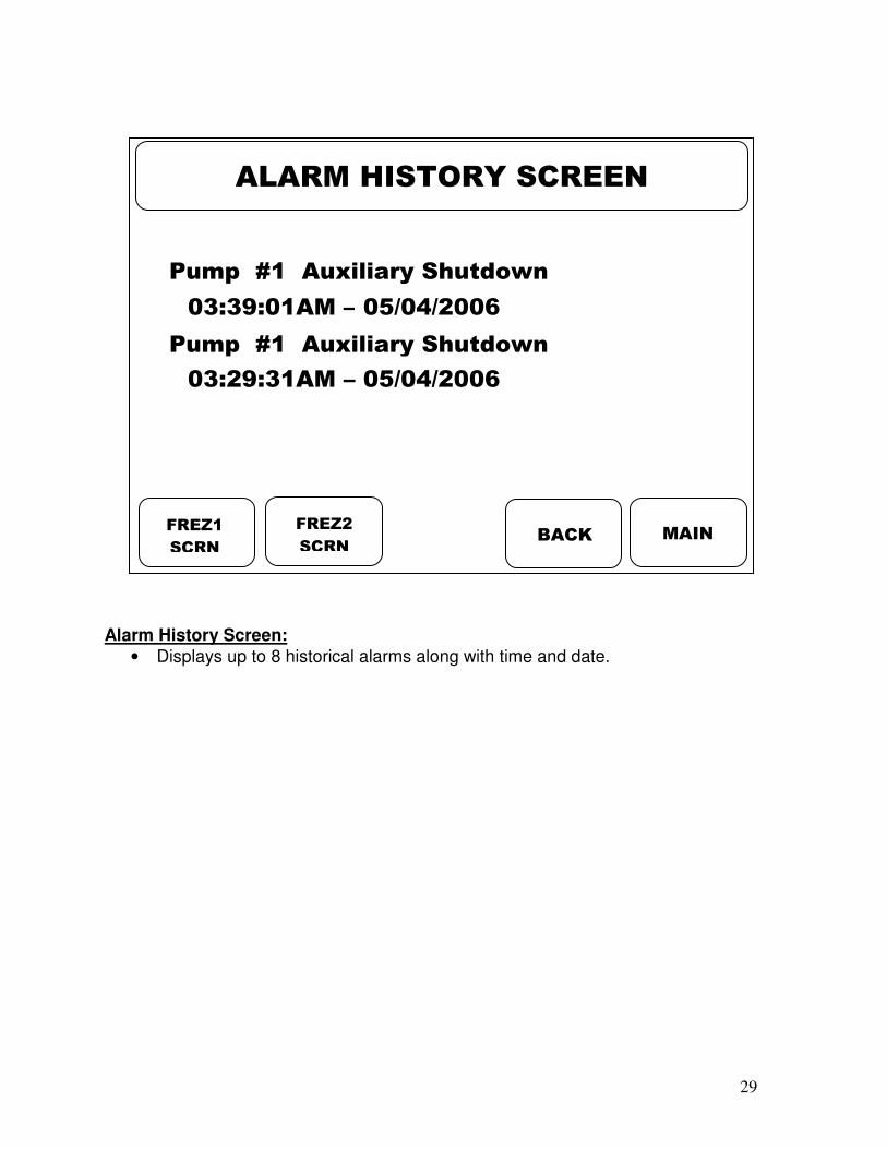
Alarm History Screen:
• Displays up to 8 historical alarms along with time and date.
MAIN
ALARM HISTORY SCREEN
BACK
Pump #1 Auxiliary Shutdown
03:39:01AM – 05/04/2006
Pump #1 Auxiliary Shutdown
03:29:31AM – 05/04/2006
FREZ1
SCRN
FREZ2
SCRN

30
Freeze Screen:
• Freezes main display at the point of failure.
• Allows the operator to view conditions at the time of failure
#1-0% Auto
05/03/2006
02:32:51 AM FREEZE
BACK MORE
PUMPS
#1-Alm Auto
#2-Alm Auto
#3-Alm Auto
VALVES
#2-0% Auto
LEVEL
45
80
60
40
20
0
100
OFF
FAILED
DIFF PRES
42.8D
COMM-S
ALARM
31
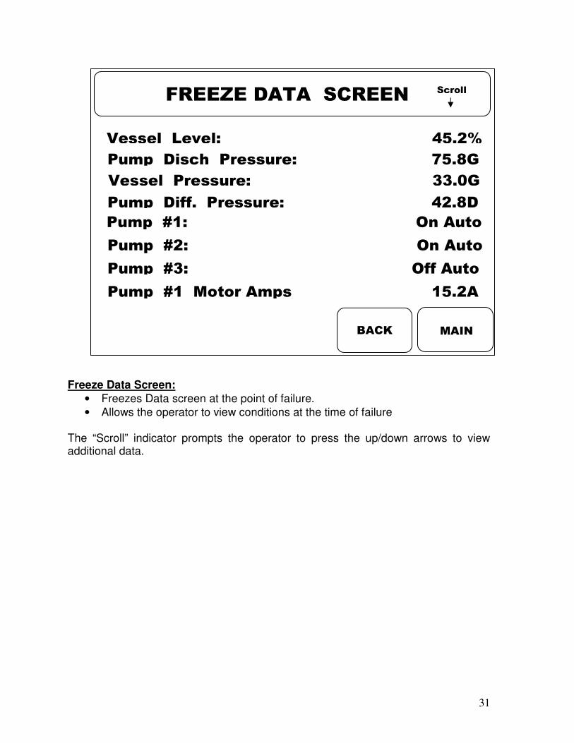
Freeze Data Screen:
• Freezes Data screen at the point of failure.
• Allows the operator to view conditions at the time of failure The “Scroll” indicator prompts the operator to press the up/down arrows to view additional data.
MAIN
FREEZE DATA SCREEN
Vessel Level: 45.2%
Pump Disch Pressure: 75.8G
Vessel Pressure: 33.0G
Pump #1: On Auto
Pump #2: On Auto
Pump Diff. Pressure: 42.8D
Pump #3: Off Auto
Pump #1 Motor Amps 15.2A
BACK
Scroll
32
Set-point Screens:
• By pressing the “Set-point Screen” soft key, the soft keys are re-written to indicate the set-point screens that can be accessed by the operator.
05/03/2006
02:32:51 AM MAIN
LEVEL
STPTS PUMP
STPTS
MOTOR
STPTS
MISC
STPTS MAIN
PUMPS
#1-Off Auto
#2-Off Auto
#3-Off Auto
VALVES
#1-0% Auto
#2-0% Auto
LEVEL
45
80
60
40
20
0
100
OFF
KEYPAD
DIFF PRES
42.8D
ALARM
COMM-S

33
Level Set-points #1 Screen: The operator can enter the vessel level % and time delay for high and low level alarms and shutdowns.
• High Level Shutdown – (Password protected) If you are in the factory set-up, the fixed high level float position can be entered. The vessel high level float switch is wired to the Matrix Micro. When the high level float trips, an alarm will be issued after the time delay entered. The time delay is not password protected.
• High Level Alarm – The high level alarm is based on the input from the level probe. The high level alarm is issued when the level reaches this set-point and remains equal to or above this set-point for the delay time period.
• Low Level Alarm – The low level alarm is based on the input from the level probe. The low level alarm is issued when the level drops to this set-point and remains equal to or below this set-point for the delay time period.
• Low Level Shutdown - The low level shutdown is based on the input from the level probe. The low level shutdown is issued when the level drops to this set-point and remains equal to or below this set-point for the delay time period. The pumps are turned off.
LEVEL
STPT2 MAIN BACK
LEVEL SETPOINTS #1
High Level Shutdown: 5 Sec
High Level Alarm: 70% 5 Sec
Low Level Alarm: 30% 5 Sec
Low Level Shutdown: 20% 5 Sec
Delay
76%
LEVEL
STPT3

34
Level Set-points #2 Screen: The operator can enter the vessel level control set-points and response rates for vessel level #1 set-points.
• Level Control Set-point #1 – The operator selects the desired level for the vessel. The controller will maintain the level in the vessel to equal this set-point.
• Dead Band #1 – The % level above and below the “Level Control set-point” where the controller takes no action.
• Proportional #1 – Proportional setting of a ”PID” control. Settings are 0-256.
• Integral #1 – Integral setting of a “PID control. Settings are 0-256.
• Derivative #1 – Derivative setting of a “PID” control. Settings are 0-99.
• Solenoid Off Diff #1 – The % level above the “Level Control set-point” where the controller cycles off the solenoid valve.
• Solenoid Off Delay #1 = This set-point sets the interval (in seconds) to delay before cycling off the solenoid valve when the level reaches the “Solenoid Off Diff #1” set-point.
Response #1: 0
MAIN BACK
LEVEL SETPOINTS #2
Level Cntrl Setpt #1: 30%
Dead Band #1: 1%
Integral #1: 5
Solenoid Off Diff #1: 0%
Solenoid Off Delay #1: 5 Sec
Proportional #1: 25
Derivative #1: 1

35
Level Set-points #3 Screen: The operator can enter the vessel level control set-points and response rates for vessel level #2 set-points.
• Level Control Set-point #2 – The operator selects the desired level for the vessel. The controller will maintain the level in the vessel to equal this set-point.
• Dead Band #2 – The % level above and below the “Level Control set-point” where the controller takes no action.
• Proportional #2 – Proportional setting of a ”PID” control. Settings are 0-256.
• Integral #2 – Integral setting of a “PID control. Settings are 0-256.
• Derivative #2 – Derivative setting of a “PID” control. Settings are 0-99.
• Solenoid Off Diff #2 – The % level above the “Level Control set-point” where the controller cycles off the solenoid valve.
• Solenoid Off Delay #2 = This set-point sets the interval (in seconds) to delay before cycling off the solenoid valve when the level reaches the “Solenoid Off Diff #2” set-point.
Response #1: 0
MAIN BACK
LEVEL SETPOINTS #3
Level Cntrl Setpt #2: 40%
Dead Band #2: 1%
Integral #2: 5
Solenoid Off Diff #2: 1%
Solenoid Off Delay #2: 5 Sec
Proportional #2: 25
Derivative #2: 1
36
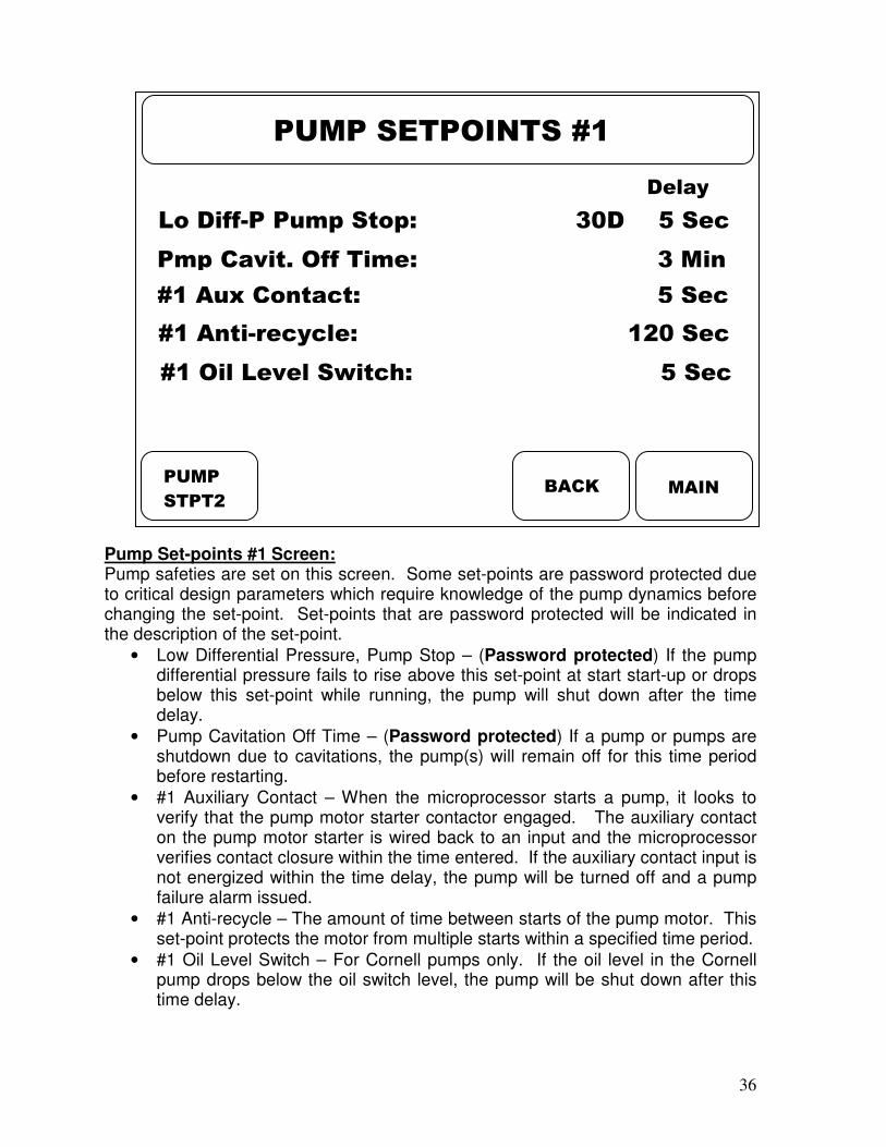
Pump Set-points #1 Screen: Pump safeties are set on this screen. Some set-points are password protected due to critical design parameters which require knowledge of the pump dynamics before changing the set-point. Set-points that are password protected will be indicated in the description of the set-point.
• Low Differential Pressure, Pump Stop – (Password protected) If the pump differential pressure fails to rise above this set-point at start start-up or drops below this set-point while running, the pump will shut down after the time delay.
• Pump Cavitation Off Time – (Password protected) If a pump or pumps are shutdown due to cavitations, the pump(s) will remain off for this time period before restarting.
• #1 Auxiliary Contact – When the microprocessor starts a pump, it looks to verify that the pump motor starter contactor engaged. The auxiliary contact on the pump motor starter is wired back to an input and the microprocessor verifies contact closure within the time entered. If the auxiliary contact input is not energized within the time delay, the pump will be turned off and a pump failure alarm issued.
• #1 Anti-recycle – The amount of time between starts of the pump motor. This set-point protects the motor from multiple starts within a specified time period.
• #1 Oil Level Switch – For Cornell pumps only. If the oil level in the Cornell pump drops below the oil switch level, the pump will be shut down after this time delay.
MAIN BACK
PUMP SETPOINTS #1
Lo Diff-P Pump Stop: 30D 5 Sec
Pmp Cavit. Off Time: 3 Min
#1 Aux Contact: 5 Sec
#1 Anti-recycle: 120 Sec
#1 Oil Level Switch: 5 Sec
PUMP
STPT2
Delay

37
Pump Set-points #2 Screen:
• Standby Pump – the operator can select which pump is the standby pump.
• #2 Auxiliary Contact – Same as “#1 Auxiliary Contact” description.
• #2 Anti-recycle – Same as “#1 anti-recycle” description.
• #2 Oil Level Switch – Same as “#1 Oil Level Switch” description.
• #3 Auxiliary Contact – Same as “#1 Auxiliary Contact” description.
• #3 Anti-recycle – Same as “#1 anti-recycle” description.
• #3 Oil Level Switch – Same as “#1 Oil Level Switch” description.
MAIN BACK
PUMP SETPOINTS #2
Standby Pump: 2
#2 Aux Contact: 5 Sec
#2 Anti-recycle 120 Sec
#2 Oil Press Switch: 5 Sec
#3 Aux Contact: 5 Sec
Delay
#3 Anti-recycle 120 Sec
#2 Oil Level Switch: 5 Sec

38
Motor Set-points #1 Screen: Motor safeties are set on this screen.
• High Amps Shutdown #1 – (Password protected) If the motor current exceeds this set-point for the time delay, the pump will be shut down and an alarm issued.
• High Amps Alarm #1 – If the motor current exceeds this set-point for the time delay, the pump will continue to run, but an alarm issued.
• Low Amps Alarm #1 – If the motor current drops below this set-point for the time delay, the pump will continue to run, but an alarm issued.
• Low Amps Shutdown #1 – (Password protected) If the motor current drops below this set-point for the time delay, the pump will be shut down and an alarm issued.
• CT Range #1 - (Password protected) Indicates the range of the motor amps of the (CT) current transformer. CT ranges are:
o 0-10 Amps, 0-30 Amps, 0-50 Amps, 0-70 Amps.
• Low Amps Bypass On - (Password protected) When the motor amps drop below this set-point, the pump bypass solenoid is opened. If there are multiple pumps running, any pump motor that is below it’s “Low Amps Bypass On” set-point, will energize the pump bypass solenoid.
• Low Amps Bypass Off - (Password protected) When the motor amps rise above this set-point, the pump bypass solenoid is closed. If there are multiple pumps running, all pump motors must be above their “Low Amps Bypass Off” set-point, in order to de-energize the pump bypass solenoid.
Delay
MAIN BACK
MOTOR SETPOINTS #1
High Amps Shtdwn #1: 10.0A 5 Sec
High Amps Alarm #1: 8.0A 5 Sec
Low Amps Alarm #1: 2.0A 5 Sec
Low Amps Shtdwn #1 1.0A 5 Sec
CT Range #1 0-10A
Low Amps Byp. On: 3.0A 5 Sec
Low Amps Byp. Off: 3.5A 5 Sec
MOTOR
STPT2
MOTOR
STPT3
Delay

39
Motor Set-points #2 Screen:
• High Amps Shutdown #2 – (Password protected) Same as “High Amps Shutdown #1” description.
• High Amps Alarm #2 – Same as “High Amps Alarm #1” description.
• Low Amps Alarm #2 – Same as “Low Amps Alarm #1” description.
• Low Amps Shutdown #2 – (Password protected) Same as “Low Amps Shutdown #1” description.
• CT Range #2 - (Password protected) Same as “CT Range #1” description.
MAIN BACK
MOTOR SETPOINTS #2
High Amps Shtdwn #2: 10.0A 5 Sec
High Amps Alarm #2: 8.0A 5 Sec
Low Amps Alarm #2: 2.0A 5 Sec
Low Amps Shtdwn #2: 1.0A 5 Sec
CT Range #2: 0-10A

40
Motor Set-points #3 Screen:
• High Amps Shutdown #3 – (Password protected) Same as “High Amps Shutdown #1” description.
• High Amps Alarm #3 – Same as “High Amps Alarm #1” description.
• Low Amps Alarm #3 – Same as “Low Amps Alarm #1” description.
• Low Amps Shutdown #3 – (Password protected) Same as “Low Amps Shutdown #1” description.
• CT Range #3 - (Password protected) Same as “CT Range #1” description.
MAIN BACK
MOTOR SETPOINTS #3
High Amps Shtdwn #3: 10.0A 5 Sec
High Amps Alarm #3: 8.0A 5 Sec
Low Amps Alarm #3: 2.0A 5 Sec
Low Amps Shtdwn #3: 1.0A 5 Sec
CT Range #3: 0-10A

41
Miscellaneous Set-points Screen:
• Alarm Horn Delay – When an alarm occurs, this set-point delays the alarm horn output for the amount of time entered.
• Power Fail Restart - After a power failure, the restart mode can be selected. (Stay off, always restart, or only if within the time limit). The time limit is defined as the “Power Restart Delay” set-point. If the power has been off for less than the “Power Restart Delay” set-point, then the pumps are re-started. If the power has been off for longer than the “Power Restart Delay” set-point, then the pumps are locked off.
• Power Restart Delay - The maximum amount of time the power can be off and allow a restart after power failure.
MAIN BACK
MISCELLANEOUS SETPOINTS
Alarm Horn Delay: 5 Sec
Power Fail Restrt: Stay Off
Power Restrt Delay: 60 Min
DATE
TIME
42
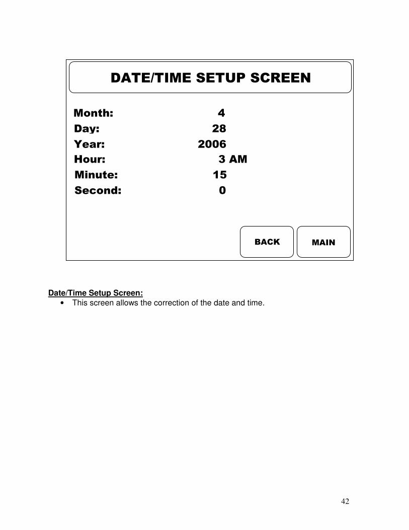
Date/Time Setup Screen:
• This screen allows the correction of the date and time.
MAIN BACK
DATE/TIME SETUP SCREEN
Month: 4
Day: 28
Year: 2006
Hour: 3 AM
Minute: 15
Second: 0

43
Additional Screens:
• By pressing the “More” soft key, the soft keys are re-written to indicate the additional screens that can be accessed by the operator.
05/03/2006
02:32:51 AM MAIN
TREND
SCRN
CALIB.
SCRN
SYSTEM
SETUP
VERSN
INFO BACK
PUMPS
#1-Off Auto
#2-Off Auto
#3-Off Auto
VALVES
#1-0% Auto
#2-0% Auto
LEVEL
45
80
60
40
20
0
100
OFF
KEYPAD
DIFF PRES
42.8D
ALARM
COMM-S

44
Minute Trend Screen #1:
• The “Minute Trend Screen” shows the High, Low and Average of the first five analog data values in minutes for up to 60 minutes.
• The “Refresh Data” key prompts the controller to start a new recording starting at the time of the key press.
The “Scroll” indicator prompts the operator to press the up/down arrows to view additional data.
MAIN
MIN. TREND SCREEN #1
SCRN#2
TREND
REFRSH
DATA
HOURLY
TREND
Scroll
05/03/2006 – 10:59:27 PM
45.2%
Pmp #2 Amps: 5.5A 5.5A 5.5A
45.2%
Pmp #1 Amps: 5.6A 5.6A 5.6A
45.2%
Disch Pres: 51.1G 50.9G 51.0G
45.2%
Ves. Pres: 20.9G 20.7G 20.8G
45.2%
Lev. Probe: 40.8% 40.6% 40.7%
45.2%
High Low Avg
45.2%

45
Minute Trend Screen #2:
• The “Minute Trend Screen” shows the High, Low and Average of the last three analog data values, in minutes, for up to 60 minutes.
• The “Refresh Data” key prompts the controller to start a new recording starting at the time of the key press.
The “Scroll” indicator prompts the operator to press the up/down arrows to view additional data.
MAIN
MIN. TREND SCREEN #2
REFRSH
DATA BACK
Scroll
05/03/2006 – 10:59:27 PM
45.2%
Mtr Val #1: 0.0% 0.0% 0.0%
45.2%
Pmp #3 Amps: 5.3A 5.3A 5.3A
45.2%
High Low Avg
45.2%
Mtr Val #2: 0.0% 0.0% 0.0%
45.2%

46
Hour Trend Screen #1:
• The “Hour Trend Screen” shows the hourly High, Low and Average of the first five analog data values every hour for 24 hours X 7 days.
The “Scroll” indicator prompts the operator to press the up/down arrows to view additional data.
MAIN
HOUR TREND SCREEN #1
SCRN#2
TREND BACK
Scroll
05/03/2006 – 10:59:27 PM
45.2%
Pmp #2 Amps: 5.5A 5.5A 5.5A
45.2%
Pmp #1 Amps: 5.6A 5.6A 5.6A
45.2%
Disch Pres: 51.1G 50.9G 51.0G
45.2%
Ves. Pres: 20.9G 20.7G 20.8G
45.2%
Lev. Probe: 40.8% 40.6% 40.7%
45.2%
High Low Avg
45.2%
47
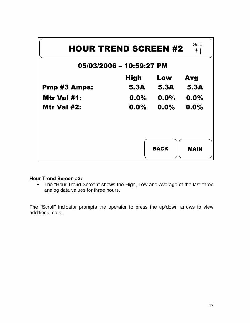
Hour Trend Screen #2:
• The “Hour Trend Screen” shows the High, Low and Average of the last three analog data values for three hours.
The “Scroll” indicator prompts the operator to press the up/down arrows to view additional data.
MAIN
HOUR TREND SCREEN #2
BACK
Scroll
05/03/2006 – 10:59:27 PM
45.2%
Mtr Val #1: 0.0% 0.0% 0.0%
45.2%
Pmp #3 Amps: 5.3A 5.3A 5.3A
45.2%
High Low Avg
45.2%
Mtr Val #2: 0.0% 0.0% 0.0%
45.2%
48
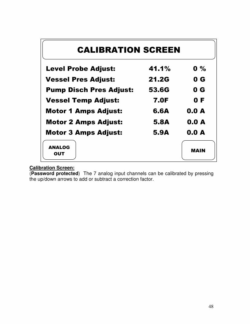
Calibration Screen: (Password protected) The 7 analog input channels can be calibrated by pressing the up/down arrows to add or subtract a correction factor.
MAIN
CALIBRATION SCREEN
Level Probe Adjust: 41.1% 0 %
Vessel Pres Adjust: 21.2G 0 G
Pump Disch Pres Adjust: 53.6G 0 G
Vessel Temp Adjust: 7.0F 0 F
Motor 1 Amps Adjust: 6.6A 0.0 A
Motor 2 Amps Adjust: 5.8A 0.0 A
Motor 3 Amps Adjust: 5.9A 0.0 A
ANALOG
OUT
49
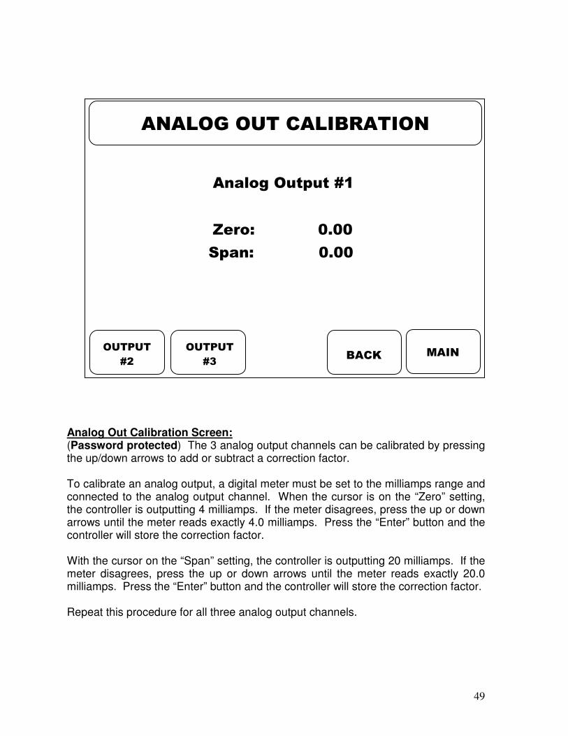
Analog Out Calibration Screen: (Password protected) The 3 analog output channels can be calibrated by pressing the up/down arrows to add or subtract a correction factor. To calibrate an analog output, a digital meter must be set to the milliamps range and connected to the analog output channel. When the cursor is on the “Zero” setting, the controller is outputting 4 milliamps. If the meter disagrees, press the up or down arrows until the meter reads exactly 4.0 milliamps. Press the “Enter” button and the controller will store the correction factor. With the cursor on the “Span” setting, the controller is outputting 20 milliamps. If the meter disagrees, press the up or down arrows until the meter reads exactly 20.0 milliamps. Press the “Enter” button and the controller will store the correction factor. Repeat this procedure for all three analog output channels.
MAIN
ANALOG OUT CALIBRATION
Analog Output #1
Zero: 0.00
Span: 0.00
OUTPUT
#2
OUTPUT
#3 BACK

50
Analog Out Calibration Screen: (Password protected) The 3 analog output channels can be calibrated by pressing the up/down arrows to add or subtract a correction factor. To calibrate an analog output, a digital meter must be set to the milliamps range and connected to the analog output channel. When the cursor is on the “Zero” setting, the controller is outputting 4 milliamps. If the meter disagrees, press the up or down arrows until the meter reads exactly 4.0 milliamps. Press the “Enter” button and the controller will store the correction factor. With the cursor on the “Span” setting, the controller is outputting 20 milliamps. If the meter disagrees, press the up or down arrows until the meter reads exactly 20.0 milliamps. Press the “Enter” button and the controller will store the correction factor. Repeat this procedure for all three analog output channels.
MAIN
ANALOG OUT CALIBRATION
Analog Output #2
Zero: 0.00
Span: 0.00
BACK

51
Analog Out Calibration Screen: (Password protected) The 3 analog output channels can be calibrated by pressing the up/down arrows to add or subtract a correction factor. To calibrate an analog output, a digital meter must be set to the milliamps range and connected to the analog output channel. When the cursor is on the “Zero” setting, the controller is outputting 4 milliamps. If the meter disagrees, press the up or down arrows until the meter reads exactly 4.0 milliamps. Press the “Enter” button and the controller will store the correction factor. With the cursor on the “Span” setting, the controller is outputting 20 milliamps. If the meter disagrees, press the up or down arrows until the meter reads exactly 20.0 milliamps. Press the “Enter” button and the controller will store the correction factor. Repeat this procedure for all three analog output channels.
MAIN
ANALOG OUT CALIBRATION
Analog Output #3
Zero: 0.00
Span: 0.00
BACK

52
Security Code Entry Screen: When the operator attempts to change a set-point that is password protected or to enter the “system Set-up” screens, this screen will appear. The proper password must be entered, pressing the enter key after each digit. The value of each digit is changed by pressing the up/down arrows.
MAIN
ACCESS RESTRICTED
Security Code: 0 0 0 0
53
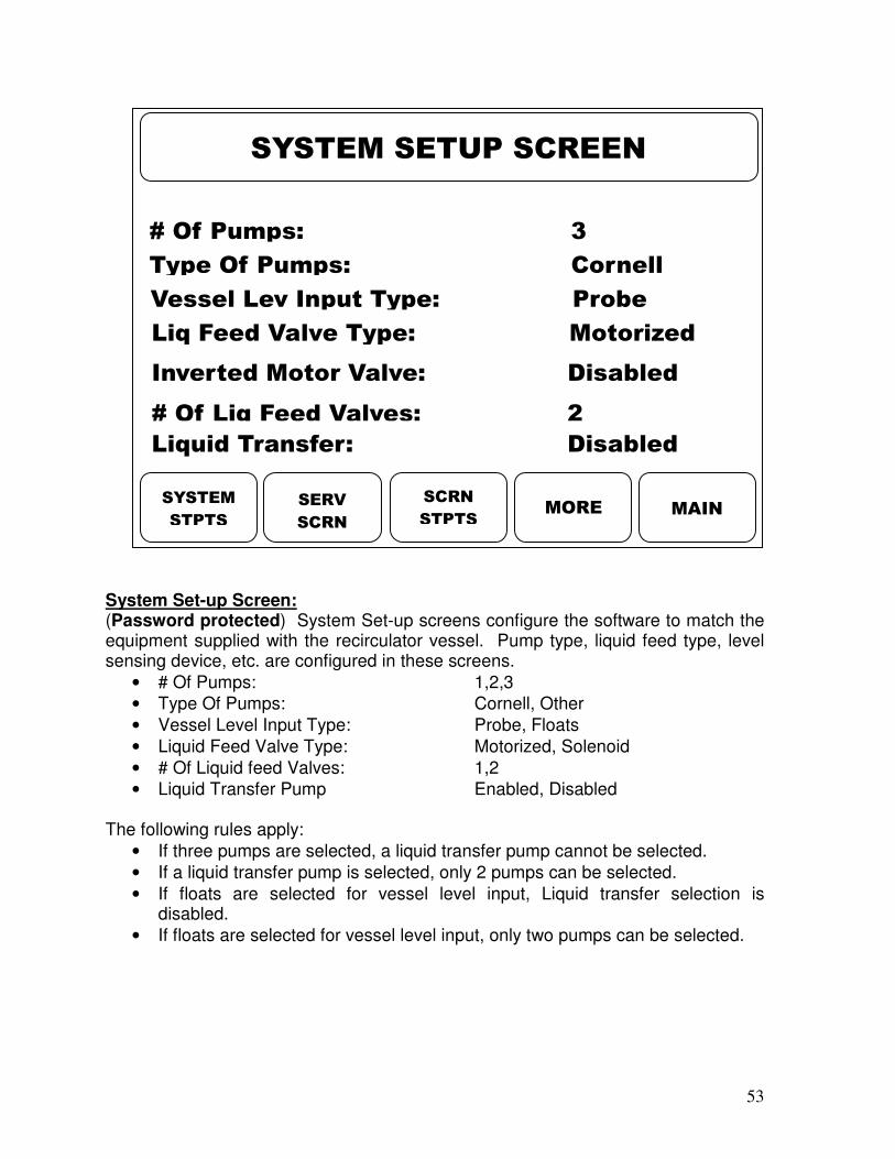
System Set-up Screen: (Password protected) System Set-up screens configure the software to match the equipment supplied with the recirculator vessel. Pump type, liquid feed type, level sensing device, etc. are configured in these screens.
• # Of Pumps: 1,2,3
• Type Of Pumps: Cornell, Other
• Vessel Level Input Type: Probe, Floats
• Liquid Feed Valve Type: Motorized, Solenoid
• # Of Liquid feed Valves: 1,2
• Liquid Transfer Pump Enabled, Disabled The following rules apply:
• If three pumps are selected, a liquid transfer pump cannot be selected.
• If a liquid transfer pump is selected, only 2 pumps can be selected.
• If floats are selected for vessel level input, Liquid transfer selection is disabled.
• If floats are selected for vessel level input, only two pumps can be selected.
MAIN MORE
SYSTEM SETUP SCREEN
# Of Pumps: 3
Type Of Pumps: Cornell
Vessel Lev Input Type: Probe
Liq Feed Valve Type: Motorized
# Of Liq Feed Valves: 2
Liquid Transfer: Disabled
SYSTEM
STPTS
SERV
SCRN
SCRN
STPTS
Inverted Motor Valve: Disabled

54
System Set-up Screen #2:
• Remote Reset Input – An input module can be added to the digital I/O board that will allow a remote pushbutton or PLC system to reset the panel remotely. This feature is enabled/disabled on this screen.
• Vessel Temperature – Vessel temperature can be measured by adding a temperature probe and well to the vessel. This feature is enabled/disabled on this screen.
• Startup Screen – If a startup mode is required for applications such as spiral freezers where the level is reset to a higher level for start-up. This feature is enabled/disabled on this screen.
• Analog Output Board – (Password Protected) If the controller does not require analog outputs, it can be disabled so that the controller is not looking for it in the software.
• Pump Auto Re-Start – Determines if a pump will automatically restart after pump cavitation or remain off.
• Pump Ramp Start – Selects between standard motor starter and soft starter.
• Pump Ramp Start Delay – If a soft starter is supplied, this set-point holds-off detection of the motor starter auxiliary and the minimum motor amps until the motor is fully up to speed.
• Analog Dampening – Selects a dampening factor for all the analog inputs. Sometimes required for vessels that have rapidly changing analog values.
MAIN BACK
SYSTEM SETUP SCREEN #2
Remote Reset Input: Enabled
Vessel Temperature: Enabled
Startup Screen: Enabled
COMM
STPTS
Analog Output Board: Enabled
Pump Auto Re-Start: Enabled
Pump Ramp Start: Enabled
Pump Ramp Start Delay: 10 Sec
Analog Dampening: 90

55
Communications Set-up Screen: Ethernet Settings:
• Slave Address – The slave address is the same as a unit ID number. If there are multiple devices on the serial or Ethernet network, this entry identifies which unit the master is communicating to.
• IP Address – Internet Protocol address is entered here.
• Subnet Mask – Internet Protocol subnet mask address is entered here. Serial Port settings:
• Baud Rate – Selects the data transfer rate. o 2400 o 4800 o 9600 o 19200
• Data bits – Selects the number of data bits. o 7 o 8
• Parity – Error checking based on parity. o Even o Odd o None
• Stop Bits – Number of stop bits. o 1 o 2
MAIN BACK
COMMUNICATIONS SETUP
Slave Address: 1
IP Address: 192.168. 0. 20
Subnet Mask: 255.255. 0. 0
Baud Rate: 19200
Data Bits: 8
Parity: Even
Stop Bits: 2

56
Digital Input Status Screen: This screen allows the service person to view the status of the digital inputs as seen by the microprocessor. An input that is not operating can be quickly diagnosed using this screen
• High Level Float: On, Off
• Remote Enable: On, Off
• Remote Reset: On, Off
• Pump #1 Auxiliary: On, Off
• Pump #1 Oil level: On, Off
• Pump #2 Auxiliary: On, Off
• Pump #2 Oil level: On, Off
• Pump #3 Auxiliary: On, Off
• Pump #3 Oil level: On, Off The “Scroll” indicator prompts the operator to press the up/down arrows to view additional data.
MAIN
DIGITAL INPUT STATUS
High Level Float: ON
Remote Enable: ON
Remote Reset: OFF
Pump #1 Oil Level: ON
Pump #2 Aux: OFF
Pump #1 Aux: OFF
Pump #2 Oil Level: ON
Pump #3 Aux: OFF
Scroll
BACK ANALOG
OUT
ANALOG
IN
DIG
OUT

57
Digital Output Status Screen: This screen allows the service person to view the status of the digital outputs as seen by the microprocessor. An output that is not operating can be quickly diagnosed using this screen
• Liquid Feed Solenoid #1: On, Off
• Liquid Feed Solenoid #2: On, Off
• Pump Bypass Solenoid: On, Off
• Alarm: On, Off
• Pump #1 Start/Stop: On, Off
• Pump #2 Start/Stop: On, Off
• Pump #3 Start/Stop: On, Off
MAIN
DIGITAL OUTPUT STATUS
Liquid Feed Solenoid #1: ON
Liquid Feed Solenoid #2: ON
Pump Bypass Solenoid: OFF
Pump #1 Start/Stop: ON
Pump #2 Start/Stop: OFF
Alarm: OFF
Pump #3 Start/Stop: ON
BACK
58
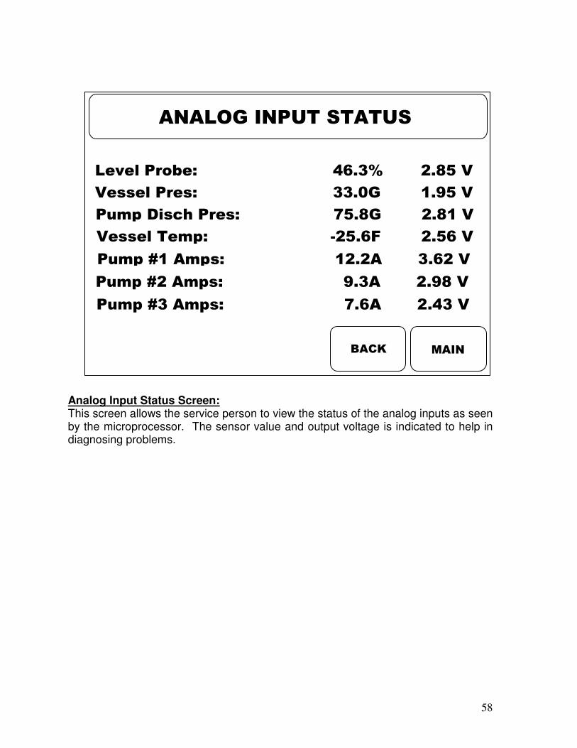
Analog Input Status Screen: This screen allows the service person to view the status of the analog inputs as seen by the microprocessor. The sensor value and output voltage is indicated to help in diagnosing problems.
MAIN BACK
ANALOG INPUT STATUS
Level Probe: 46.3% 2.85 V
Vessel Pres: 33.0G 1.95 V
Pump Disch Pres: 75.8G 2.81 V
Vessel Temp: -25.6F 2.56 V
Pump #1 Amps: 12.2A 3.62 V
Pump #2 Amps: 9.3A 2.98 V
Pump #3 Amps: 7.6A 2.43 V

59
Analog Output Status Screen: This screen allows the service person to view the status of the analog outputs as seen by the microprocessor. The output current is indicated to help in diagnosing problems.
MAIN BACK
ANALOG OUTPUT STATUS
Motor Liq Feed Valve #1: 6.3 mA
Motor Liq Feed Valve #2: 4.9 mA
Vessel Level Signal: 14.2 mA

60
Screen Saver Setup Screen:
• Screen Saver – Enables/disables the screen saver, which is displayed as the RVS logo. If the screen saver is enabled, it will revert to the RVS logo after the screen saver time delay has timed out. If disabled, the last screen viewed will stay active.
• Screen Saver Delay – Starts timing from the last key entry. If there has been no keypad activity for the delay period, the screen will revert to the RVS logo.
• Back Light Delay (o=Disable) – The display backlight can be turned off after the delay period. The delay period starts after the last key entry. When the time delay times out, the display light is turned off. If “0” is entered, the display back light remains on continuously.
• Screen Contrast – The screen contrast can be adjusted for better viewing. By pressing the up/down arrows, the screen contrast can be changed.
o Screen contrast set to zero = very light text. o Screen contrast set to 15-25 = best viewability o Screen contrast set to 31 = very dark background.
MAIN BACK
SCREEN SAVER SETUP
Screen Saver: Enabled
Screen Saver Delay: 60 Sec
Bck Lght Delay (0=Dis.): 300 Sec
Screen Contrast: 24
61
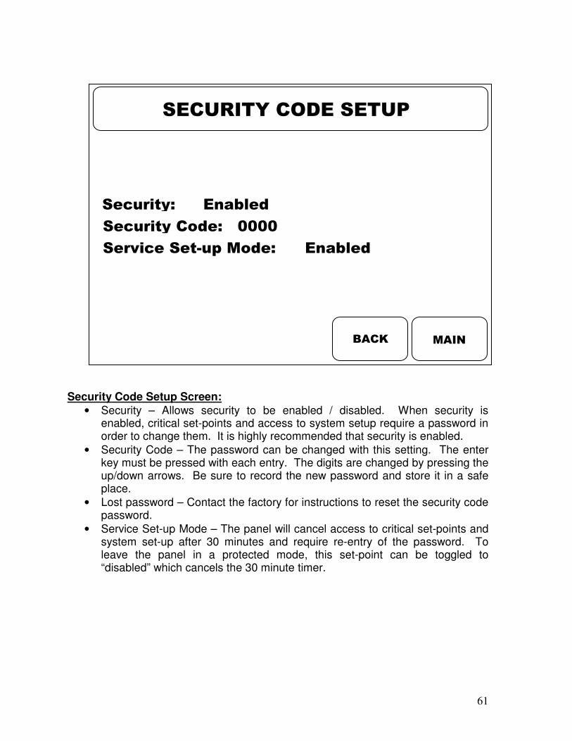
Security Code Setup Screen:
• Security – Allows security to be enabled / disabled. When security is enabled, critical set-points and access to system setup require a password in order to change them. It is highly recommended that security is enabled.
• Security Code – The password can be changed with this setting. The enter key must be pressed with each entry. The digits are changed by pressing the up/down arrows. Be sure to record the new password and store it in a safe place.
• Lost password – Contact the factory for instructions to reset the security code password.
• Service Set-up Mode – The panel will cancel access to critical set-points and system set-up after 30 minutes and require re-entry of the password. To leave the panel in a protected mode, this set-point can be toggled to “disabled” which cancels the 30 minute timer.
MAIN BACK
SECURITY CODE SETUP
Security: Enabled
Security Code: 0000
Service Set-up Mode: Enabled

62
Initialize Set-points Screen:
• Returns all set-points to factory default.
• Yes/NO
CAUTION!!!: SELECTING “YES” WILL CAUSE ALL CURRENT SETTINGS TO BE LOST.
MAIN BACK
INITIALIZE SETPOINTS
Initialize Setpoints: NO

63
Pump Run Hours Screen:
• If a microprocessor board is replaced, the run hours can be corrected with this screen.
MAIN BACK
PUMP RUN HOURS SCREEN
Pump 1 Run Hours: 000000
Pump 2 Run Hours: 000000
Pump 3 Run Hours: 000000

64
Program Version Information Screen:
• Indicated the current software program version and release date.
• Be sure and record this information when requesting assistance from the Service Department.
MAIN
PROGRAM VERSION INFO
Program Version: VER 1.75
Release Date: Sep. 10, 2010

65
SET-POINT TABLE Screen Set-point Description “X” Setting Range Mode Micro Start Mode Normal/Startup
Mode Pump #1 Mode On/Off/Auto
Mode Pump #2 Mode On/Off/Auto
Mode Pump #3Mode On/Off/Auto
Mode Liquid Feed #1 Mode On/Off/Auto/ Manual
Mode Liquid Feed #2 Mode On/Off/Auto/ Manual
Startup Set-up Level Control Set-point Adjust 10% 0-50%
Startup Set-up Startup Time 30 Min 1-120 Min
Level Set-points #1 High Level Shutdown 80% 50-100%
Level Set-points #1 High Level Shutdown Delay 5 Sec 0-10 Sec
Level Set-points #1 High Level Alarm 60% 50-100%
Level Set-points #1 High Level Alarm Delay 5 Sec 0-10 Sec
Level Set-points #1 Low Level Alarm 30% 0-50% Level Set-points #1 Low Level Alarm Delay 5 Sec 0-10 Sec
Level Set-points #1 Low Level Shutdown 10% 0-50%
Level Set-points #1 Low Level Shutdown Delay 5 Sec 0-10 Sec
Level Set-points #1 Level Control Set-point #1 40% 0-100%
Level Set-points #1 Dead Band #1 1% 0-5%
Level Set-points #1 Proportional #1 25 0-256
Level Set-points #1 Integral #1 5 0-256
Level Set-points #1 Derivative #1 1 0-99
Level Set-points #1 Solenoid Off Diff #1 5% 1-100%
Level Set-points #1 Solenoid Off Delay #1 5 Sec 0-10 Sec
Level Set-points #1 Level Control Set-point #2 50% 0-100%
Level Set-points #1 Dead Band #2 1% 0-5%
Level Set-points #1 Proportional #2 25 0-256
Level Set-points #1 Integral #2 5 0-256
Level Set-points #1 Derivative #2 1 0-99
Level Set-points #1 Solenoid Off Diff #2 5% 1-100%
Level Set-points #1 Solenoid Off Delay #2 5 Sec 0-10 Sec
Level Set-points #1 Liquid Transfer On 70% 50-100%
Level Set-points #1 Liquid Transfer On Delay 5 Sec 0-10 Sec
Level Set-points #1 Liquid Transfer Off 65% 50-100%
Level Set-points #1 Liquid Transfer Off Delay 5 Sec 0-10 Sec
Level Set-points #1 Level Control Float #1 5 Sec 0-10 Sec
Level Set-points #1 Level Control Float #2 5 Sec 0-10 Sec
Pump Set-points #1 Low Diff Press Pump Stop X 25 Psi 0-200Psi
Pump Set-points #1 Low Diff Press Pump Stop Delay X 5 Sec 0-10 Sec
Pump Set-points #1 Pump Cavitation Off Time X 3 Min 0-10 Min
Pump Set-points #1 #1 Auxiliary Contact 5 Sec 0-10 Sec
Pump Set-points #1 #1 Anti-recycle 20 Sec 0-120 Sec
Pump Set-points #1 #1 Oil Level Switch 5 Sec 0-10 Sec
Pump Set-points #2 Standby Pump 2 1,2,3
Pump Set-points #2 #2 Auxiliary Contact 5 Sec 0-10 Sec
Pump Set-points #2 #2 Anti-recycle 20 Sec 0-120 Sec
Pump Set-points #2 #2 Oil Level Switch 5 Sec 0-10 Sec

66
Pump Set-points #2 #3 Auxiliary Contact 5 Sec 0-10 Sec
Pump Set-points #2 #3 Anti-recycle 20 Sec 0-120 Sec
Pump Set-points #2 #3 Oil Level Switch 5 Sec 0-10 Sec
Motor Set-points #1 High Amps Shutdown #1 X 0-100 A
Motor Set-points #1 High Amps Shutdown #1 Delay X 5 Sec 0-10 Sec
Motor Set-points #1 High Amps Alarm #1 0-100 A
Motor Set-points #1 High Amps Alarm #1 Delay 5 Sec 0-10 Sec
Motor Set-points #1 Low Amps Alarm #1 0-100 A
Motor Set-points #1 Low Amps Alarm #1 Delay 5 Sec 0-10 Sec
Motor Set-points #1 Low Amps Shutdown #1 X 0-100 A
Motor Set-points #1 Low Amps Shutdown #1 Delay X 5 Sec 0-10 Sec
Motor Set-points #1 CT Range #1 X 10A, 30A, 50A,70A
Motor Set-points #1 Low Amps Bypass On X 0-100 A
Motor Set-points #1 Low Amps Bypass On Delay X 5 Sec 0-10 Sec
Motor Set-points #1 Low Amps Bypass Off X 0-100 A
Motor Set-points #1 Low Amps Bypass Off Delay X 5 Sec 0-10 Sec
Motor Set-points #2 High Amps Shutdown #2 X 0-100 A
Motor Set-points #2 High Amps Shutdown #2 Delay X 5 Sec 0-10 Sec
Motor Set-points #2 High Amps Alarm #2 0-100 A
Motor Set-points #2 High Amps Alarm #2 Delay 5 Sec 0-10 Sec
Motor Set-points #2 Low Amps Alarm #2 0-100 A
Motor Set-points #2 Low Amps Alarm #1 Delay 5 Sec 0-10 Sec
Motor Set-points #2 Low Amps Shutdown #2 X 0-100 A
Motor Set-points #2 Low Amps Shutdown #2 Delay X 5 Sec 0-10 Sec
Motor Set-points #2 CT Range #2 X 10A, 30A, 50A,70A
Motor Set-points #3 High Amps Shutdown #3 X 0-100 A
Motor Set-points #3 High Amps Shutdown #3 Delay X 5 Sec 0-10 Sec
Motor Set-points #3 High Amps Alarm #3 0-100 A
Motor Set-points #3 High Amps Alarm #3 Delay 5 Sec 0-10 Sec
Motor Set-points #3 Low Amps Alarm #3 0-100 A
Motor Set-points #3 Low Amps Alarm #3 Delay 5 Sec 0-10 Sec
Motor Set-points #3 Low Amps Shutdown #3 X 0-100 A
Motor Set-points #3 Low Amps Shutdown #3 Delay X 5 Sec 0-10 Sec
Motor Set-points #3 CT Range #3 X 10A, 30A, 50A,70A
Miscellaneous Set-points Alarm Horn Delay 5 Sec 0-10 Sec
Miscellaneous Set-points Power Fail Restart Stay off, Always,
Time limit
Miscellaneous Set-points Power Restart Delay 60 Min 0-240 Min
Miscellaneous Set-points Date/Time Setup
System Set-up # Of Pumps X 2 1,2,3
System Set-up Type Of Pumps X Other Other, Cornell
System Set-up Vessel Level Input Type X Probe Probe, Float
System Set-up Liquid Feed Valve Type X Motorized Motorized, Solenoid
System Set-up Inverted Motor Valve X Disabled Enabled, Disabled
System Set-up # Of Liquid Feed Valves X 1 1,2
67
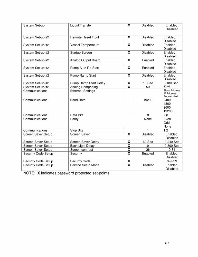
System Set-up Liquid Transfer X Disabled Enabled, Disabled
System Set-up #2 Remote Reset Input X Disabled Enabled, Disabled
System Set-up #2 Vessel Temperature X Disabled Enabled, Disabled
System Set-up #2 Startup Screen X Disabled Enabled, Disabled
System Set-up #2 Analog Output Board X Enabled Enabled, Disabled
System Set-up #2 Pump Auto Re-Start X Enabled Enabled, Disabled
System Set-up #2 Pump Ramp Start X Disabled Enabled, Disabled
System Set-up #2 Pump Ramp Start Delay X 10 Sec 0-180 Sec.
System Set-up #2 Analog Dampening X 50 40-99
Communications Ethernet Settings Slave Address IP Address Subnet Mask
Communications Baud Rate 19200 2400 4800 9600 19200
Communications Data Bits 8 7,8
Communications Parity None Even Odd None
Communications Stop Bits 1 1,2
Screen Saver Setup Screen Saver X Disabled Enabled, Disabled
Screen Saver Setup Screen Saver Delay X 60 Sec 0-240 Sec
Screen Saver Setup Back Light Delay X 0 0-300 Sec
Screen Saver Setup Screen contrast X 26 0-31
Security Code Setup Security X Enabled Enabled, Disabled
Security Code Setup Security Code X 0-9999
Security Code Setup Service Setup Mode X Disabled Enabled, Disabled
NOTE: X indicates password protected set-points

68
JUMPER TABLES: ANALOG I/O BOARD Analog Input Ch #1 0-5 V JP1 - Out JP2 - Out JP3 - Out
Vessel Level X 4-20 mA JP1 - In JP2 - Out JP3 - Out
ICTD JP1 - Out JP2 - In JP3 - Out
Analog Input Ch #2 Vessel Pressure X 0-5 V JP4 - Out JP5 - Out
4-20 mA JP4 - In JP5 - Out
ICTD JP4 - Out JP5 - In
Analog Input Ch #3 Pump Disch Press X 0-5 V JP6 - Out JP7 - Out
4-20 mA JP6 - In JP7- Out
ICTD JP6 - Out JP7 - In
Analog Input Ch #4 0-5 V JP8 - Out JP9 - Out
4-20 mA JP8 - In JP9 - Out
Vessel Temp X ICTD JP8 - Out JP9 - In
Analog Input Ch #5 Pump #1 Amps 0-10 A JP10 - Out JP11 - Out JP12 - Out
0-30 A JP10 - In JP11 - Out JP12 - Out
0-50 A JP10 - Out JP11 - In JP12 - Out
0-70 A JP10 - Out JP11 - Out JP12 - In
Analog Input Ch #6 Pump #2 Amps 0-10 A JP13 - Out JP14 - Out JP15 - Out
0-30 A JP13 - In JP14 - Out JP15 - Out
0-50 A JP13 - Out JP14 - In JP15 - Out
0-70 A JP13 - Out JP14 - Out JP15 - In
Analog Input Ch #7 Pump #3 Amps 0-10 A JP16 - Out JP17 - Out JP18 - Out
0-30 A JP16 - In JP17 - Out JP18 - Out
0-50 A JP16 - Out JP17 - In JP18 - Out
0-70 A JP16 - Out JP17 - Out JP18 - In
Analog Input Ch #8 Not Used
Analog Output Ch #1 Liquid Valve #1 X 4-20 mA JP22 (1-2) JP23 (1-2)
Analog Output Ch #2 Liquid Valve #2 X 4-20 mA JP24 (1-2) JP25 (1-2)
Analog Output Ch #3 Level Signal 4-20 mA
Analog Output Ch #4 Not Used
NOTE: X indicates recommended jumper settings

69
JUMPER TABLES:
Display Interface Board GPO Display X JP2 (1-2) JP3 (1-3)
Optrex Display JP2 (2-3) JP3 (2-3) Display frame to DC ground JP1 - In NOTE: X indicates recommended jumper settings CPU Board
J7 X Not Installed J8 X Not Installed
JP10 X (1-2) (4-6) RS-485 Termination NOTE: X indicates recommended jumper settings
HARDWARE SPECIFICATIONS INPUT POWER
o 105 – 125 VAC 47 – 63 Hz * Standard o 185 – 250 VAC 47 – 63 Hz *Optional (Contact factory)
DC OUTPUT POWER
o 5 VDC @ 2A (10 Watts) o 24 VDC @ 1A (24 Watts)
ENVIRONMENTAL
o Operating temperature -4ºF to 131ºF (-20ºC to 55ºC) o Storage temperature -13ºF to 140ºF (-25ºC to 60ºC) o Humidity (non condensing) 0% to 95% o Vibration 2.0g’s (19.61m/s2) o Shock 100g’s (980m/s2) o RFI Immunity 15v/m (15MHz to 1.5gHz) o EMI Immunity Complies with CE EMC directive
DISPLAY
o Dot format 320 x 240 ¼ VGA o Display mode FSTN, Positive, Transflective o Backlight Green LED o Brightness 28 cd/m2

70
KEYPAD
o Material Polycarbonate o Switches Stainless steel snap domes
CERTIFICATIONS
o UL 508A o cUL
STAND-ALONE PANEL
o Dimensions 17”x15”x7” (35.6x40.6x20.3 cm) o Weight o Design NEMA 4X o Material Fiberglass o Finish RVS blue paint
INTEGRATED STARTER PANEL
o Dimensions 30”x30”x8” (76.2x76.2x20.3 cm) o Weight o Design NEMA 4 o Material Painted steel o Finish RVS blue paint
INPUT/OUTPUT MODULES
o 120 VAC Input IACM5 (90 – 140 VAC) o 230 VAC Input (optional) IACM5A (180 – 280 VAC) o Output OACM5 (24 – 280 VAC) o *note, 230 VAC control is an option.
DIGITAL I/O (With Analog Level Probe for measuring vessel level)
o 0 Output Liquid feed solenoid #1 o 1 Output Liquid feed solenoid #2 o 2 Output Pump bypass solenoid o 3 Output Alarm o 4 Output Pump #1 start/stop o 5 Output Pump #2 start/stop o 6 Output Pump #3 start/stop o 7 Input High Level float switch o 8 Input Remote enable o 9 Input Remote reset o 10 Input Pump #1 motor starter Aux o 11 Input Pump #1 oil level switch o 12 Input Pump #2 motor starter Aux o 13 Input Pump #2 oil level switch

71
o 14 Input Pump #3 motor starter Aux o 15 Input Pump #3 oil level switch
DIGITAL I/O (With Float Switches for measuring vessel level)
o 0 Output Liquid feed solenoid #1 o 1 Output Liquid feed solenoid #2 o 2 Output Pump bypass solenoid o 3 Output Alarm o 4 Output Pump #1 start/stop o 5 Output Pump #2 start/stop o 6 Input High Level Float o 7 Input Remote Enable o 8 Input Remote Reset o 9 Input Pump #1 Motor Starter Aux. o 10 Input Pump #1 Oil Level Switch o 11 Input Pump #2 Motor Starter Aux. o 12 Input Pump #2 Oil Level Switch o 13 Input Level Control Float Switch #2 o 14 Input Level Control Float Switch #1 o 15 Input Low Level Float Switch
ANALOG INPUTS
o 1 Level probe o 2 Vessel pressure o 3 Pump discharge pressure o 4 Vessel temperature o 5 Pump #1 motor amps o 6 Pump #2 motor amps o 7 Pump #3 motor amps o 8 Not used
ANALOG OUTPUTS
o 1 4-20mA Motorized liquid feed valve #1 o 2 4-20mA Motorized liquid feed valve #2 o 3 4-20mA Liquid level to system o 4 Not used o 5 Not used o 6 Not used o 7 Not used o 8 Not used
SENSORS
o Pressure

72
o Material 100% stainless steel welded parts o Over pressure 2X Range o Burst pressure 5X Range o Technology Signal-conditioned silicon strain gauge o Range 0-200 PSIA (29.9”hg to 185.7 PSI) o Output 1-5 VDC or 4-20 mA o Accuracy +/- 1% of span o Excitation voltage 9-30 VDC o Temperature range -67ºF to 221ºF (-55ºC to 105ºC)
o Temperature
o Technology ICTD o Range -67ºF to 302ºF (-55ºC to 150ºC) o Output 1uA/ºKelvin o Accuracy +/- 2ºC over range o Excitation voltage 4 to 30 VDC
o Level
o Technology Capacitance probe o Range 20’’ to 168” @9 sizes (50.8 to 426.7 cm) o Output 4-20 mA o Accuracy +/- 1% of full scale o Excitation voltage 24 VAC or VDC o Temperature range -76ºF to 212ºF (-60ºC to 100ºC)
o Motor current o Technology Current transformer o Range 0-10, 0-30, 0-50 Amps o Output 1000:1 o Accuracy +/- 2% o Temperature range -76ºF to 212ºF (-60ºC to 100ºC)
COMMUNICATIONS
o Serial port #1 o Type RS-485 o Protocol MODBUS RTU o Baud rate 9.6K to 115K baud
o High speed Port #1 o Type Ethernet o Protocol MODBUS Ethernet o Data rate 10mb/s

73
N.C. N.C.

74
ANALOG I/O BOARD
+24VDC
GND
+5VDC
ANALOG OUTPUTS
ANALOG INPUTS
ANALOG
OUTPUT
BOARD
(PIGGYBACK)
CHAN
NEL
#3
LIQUID
LEVEL
SIGNAL
CHAN
NEL
#4
-NOT U
SED-
CHAN
NEL
#2
MOTO
RIZ
ED L
IQ. F
EED V
ALVE
CHAN
NEL
#1
MOTO
RIZ
ED L
IQ. F
EED V
ALVE
CHANNEL #8-NOT USED-
CHANNEL #7PUMP #3 MOTER AMPS
CHANNEL #6PUMP #2 MOTOR AMPS
CHANNEL #5PUMP #1 MOTOR AMPS
CHANNEL #4VESSEL TEMPERATURE
CHANNEL #3PUMP DISCHARGE PRESS.
CHANNEL #2VESSEL PRESSURE
CHANNEL #1VESSEL LEVEL

75
REMOTE ENABLE
REMOTE RESET
PUMP #1 AUX
PUMP #1 OIL LEVEL
PUMP #2 AUX
PUMP #2 OIL LEVEL
PUMP #3 AUX
PUMP #3 OIL LEVEL
HIGH LEVEL FLOAT SWITCH
PUMP #3 START
PUMP #2 START
PUMP #1 START
ALARM
PUMP BYPASS SOLENOID
LIQUID FEED SOLENOID #2
LIQUID FEED SOLENOID #1
INPUT
+5VDC POWER
DIGITAL I/O BOARD (LEVEL PROBE)
GROUND
INPUT
INPUT
INPUT
INPUT
INPUT
INPUT
INPUT
INPUT
OUTPUT
OUTPUT
OUTPUT
OUTPUT
OUTPUT
OUTPUT
OUTPUT

76
REMOTE ENABLE
REMOTE RESET
PUMP #1 AUX
PUMP #1 OIL LEVEL
PUMP #2 AUX
PUMP #2 OIL LEVEL
LEVEL CONTROL FLOAT SWITCH 1
LOW LEVEL FLOAT SWITCH
HIGH LEVEL FLOAT SWITCH
PUMP #2 START
PUMP #1 START
ALARM
PUMP BYPASS SOLENOID
LIQUID FEED SOLENOID #2
LIQUID FEED SOLENOID #1
INPUT
+5VDC POWER
DIGITAL I/O BOARD (FLOAT SWITCHES)
GROUND
INPUT
INPUT
INPUT
INPUT
INPUT
INPUT
INPUT
INPUT
OUTPUT
OUTPUT
OUTPUT
OUTPUT
OUTPUT
OUTPUT
LEVEL CONTROL FLOAT SWITCH 2INPUT

77
DC
P
OW
ER
S
UP
PL
Y
AN
ALO
GO
UT
PU
TB
OA
RD
(PIG
GY
BA
CK
)
OUTPUT
OUTPUT
OUTPUT
OUTPUT
OUTPUT
OUTPUT
OUTPUT
INPUT
INPUT
INPUT
INPUT
INPUT
INPUT
INPUT
INPUT
INPUT
LO
AD
RA
TIN
G V
OL
TS
XX
XX
HP
XX
XX

78
LO
W L
EV
EL
PU
MP
ST
OP
OP
TIO
N
PU
MP
#3
OIL
LE
VE
L(A
S R
EQ
. FO
R C
OR
NE
LL
PU
MP
S)
PU
MP
#3
AU
X
PU
MP
#2
OIL
LE
VE
L(A
S R
EQ
. FO
R C
OR
NE
LL
PU
MP
S)
PU
MP
#2
AU
X
VA
RIS
TO
R O
R S
UR
GE
SU
PP
RE
SS
ION
DE
VIC
E.
(NO
T S
UP
PL
IED
BY
MA
NU
FA
CT
UR
ER
)
CO
RN
EL
PU
MP
#3
HE
AT
ER
(AS
RE
Q. F
OR
CO
RN
EL
L P
UM
PS
)
CO
RN
EL
PU
MP
#2
HE
AT
ER
(AS
RE
Q. F
OR
CO
RN
EL
L P
UM
PS
)
CO
RN
EL
PU
MP
#1
HE
AT
ER
(AS
R
EQ
. FO
R C
OR
NE
LL P
UM
PS
)
PA
NE
L H
EA
TE
R
PU
MP
#1
OIL
LE
VE
L
(AS
RE
Q. F
OR
CO
RN
ELL
PU
MP
S)
PU
MP
#1
AU
X
RE
MO
TE
RE
SE
T
RE
MO
TE
EN
AB
LE
HIG
H L
EV
EL
FLO
AT
SW
ITC
H
PU
MP
#3
ST
AR
T
PU
MP
#2
ST
AR
T
PU
MP
#1
ST
AR
T
AL
AR
M
PU
MP
BY
PA
SS
SO
LE
NO
ID
LIQ
UID
FE
ED
SO
LE
NO
ID #
2
LIQ
UID
FE
ED
SO
LE
NO
ID #
1

79
RS
-485
CO
MM
DE
VIC
E(B
Y C
US
TO
ME
R)
MA
TR
IX C
PU
J10
RS
-23
2/R
S-4
85
C
ON
VE
RT
ER
TE
RM
S D
B-9
CH
AN
NE
L #
1M
OT
OR
IZE
D L
IQU
ID F
EE
D V
ALV
E #
1
CH
AN
NE
L #
2M
OT
OR
IZE
D L
IQU
ID F
EE
D V
ALV
E #
2
CH
AN
NE
L #
3L
IQU
ID L
EV
EL S
IGN
AL
CH
AN
NE
L #
4U
NU
SE
D
CH
AN
NE
L #
1V
ES
SE
L L
EV
EL
CH
AN
NE
L #
2V
ES
SE
L P
RE
SS
UR
E
CH
AN
NE
L #
5P
UM
P #
1 M
OT
OR
AM
PS
CH
AN
NE
L #
4V
ES
SE
L T
EM
PE
RA
TU
RE
CH
AN
NE
L #
3P
UM
P D
ISC
HA
RG
E P
RE
SS
UR
E
CH
AN
NE
L #
6P
UM
P #
2 M
OT
OR
AM
PS
CH
AN
NE
L #
7P
UM
P #
3 M
OT
OR
AM
PS
CH
AN
NE
L #
8U
NU
SE
D

1
MATRIX MICROPROCESSOR
CONTROL
COMMUNICATIONS ADDENDUM
6-12-09
REV-1.8

2
INDEX
• Introduction………………………………………………………………………. 3
• Display Screen………………………………………………………………….. 4
• Digital I/O …………………..…………………………………………………… 5
• Analog I/O ……………………..……………………………..………………… 6
• Status………………………………………………………………………………7
• Clock Set-points………………………………………………………………….. 7
• Set-points……………………………………………………………………….. 8
• Jumper table…………………………………………………………………….. 12
• Drawings………………….…………………………………………………….. 13

3
INTRODUCTION
The RVS Matrix Microprocessor Control utilizes two communications formats, based on Modbus protocol, to interface to supervisory control systems. The physical interfaces are RS-485 and Ethernet. The RS485 interface utilizes Modbus RTU and the Ethernet interface utilizes Modbus IP. The following pages will describe the communications functionality and the “code sets” related to the data and set-points within the Matrix Micro.

4
Communications Set-up Screen: Ethernet Settings:
• Slave Address – The slave address is the same as a unit ID number. If there are multiple devices on the serial or Ethernet network, this entry identifies which unit the master is communicating to.
• IP Address – Internet Protocol address is entered here.
• Subnet Mask – Internet Protocol subnet mask address is entered here. Serial Port settings:
• Baud Rate – Selects the data transfer rate. o 2400 o 4800 o 9600 o 19200
• Data bits – Selects the number of data bits. o 7 o 8
• Parity – Error checking based on parity. o Even o Odd o None
• Stop Bits – Number of stop bits. o 1 o 2
MAIN BACK
COMMUNICATIONS SETUP
Slave Address: 1
IP Address: 192.168. 0. 20
Subnet Mask: 255.255. 0. 0
Baud Rate: 19200
Data Bits: 8
Parity: Even
Stop Bits: 2

5
DIGITAL I/O (Read Only)
WITH LEVEL PROBE WITH FLOAT SWITCHES
MODBUS ADDRESS
DESCRIPTION MODULE TYPE
MODULE TYPE
MODULE TYPE
VALUE
43001 Liquid feed solenoid #1 Output Liquid feed solenoid #1 Output 0 = Off 1 = On
43002 Liquid feed solenoid #2 Output Liquid feed solenoid #2 Output 0 = Off 1 = On
43003 Pump bypass solenoid Output Pump bypass solenoid Output 0 = Off 1 = On
43004 Alarm Output Alarm Output 0 = Off 1 = On
43005 Pump #1 start/stop Output Pump #1 start/stop Output 0 = Off 1 = On
43006 Pump #2 start/stop Output Pump #2 start/stop Output 0 = Off 1 = On
43007 Pump #3 start/stop Output Level control float switch #2 Input 0 = Off 1 = On
43008 High level float switch Input High level float switch Input 0 = Off 1 = On
43009 Remote enable Input Remote enable Input 0 = Off 1 = On
43010 Remote reset Input Remote reset Input 0 = Off 1 = On
43011 Pump #1 motor starter Aux Input Pump #1 motor starter Aux Input 0 = Off 1 = On
43012 Pump #1 oil level switch Input Pump #1 oil level switch Input 0 = Off 1 = On
43013 Pump #2 motor starter Aux Input Pump #2 motor starter Aux Input 0 = Off 1 = On
43014 Pump #2 oil level switch Input Pump #2 oil level switch Input 0 = Off 1 = On
43015 Pump #3 motor starter Aux Input Level control float switch #1 Input 0 = Off 1 = On
43016 Pump #3 oil level switch Input Low level float switch Input 0 = Off 1 = On
43017 Future Input Future Input 0 = Off 1 = On
43018 Future Input Future Input 0 = Off 1 = On
43019 Future Input Future Input 0 = Off 1 = On
43020 Future Input Future Input 0 = Off 1 = On
43021 Future Input Future Input 0 = Off 1 = On
43022 Future Input Future Input 0 = Off 1 = On
43023 Future Input Future Input 0 = Off 1 = On
43024 Future Input Future Input 0 = Off 1 = On
43025 Future Input Future Input 0 = Off 1 = On
43026 Future Input Future Output 0 = Off 1 = On
43027 Future Output Future Output 0 = Off 1 = On

6
ANALOG I/O (Read Only) MODBUS ADDRESS
DESCRIPTION TYPE VALUE RANGE
43028 Vessel level Input Value x 10 0-100% 43029 Vessel pressure Input Value x 10 0 to 200 PSIA
43030 Pump discharge pressure Input Value x 10 0 to 200 PSIA 43031 Vessel temperature Input Value x 10 -459F to 440F 43032 Pump #1 motor amps Input Value x 10 0-100A 43033 Pump #2 motor amps Input Value x 10 0-100A 43034 Pump #3 motor amps Input Value x 10 0-100A 43035 Future Input Value x 10 43036 Future Input Value x 10 43037 Future Input Value x 10 43038 Future Input Value x 10 43039 Motorized feed valve #1 Output Value x 10 0-100% 43040 Motorized feed valve #2 Output Value x 10 0-100% 43041 Liquid level signal Output Value x 10 0-100% 43042 Future Output Value x 10
43043 Future Output Value x 10 43044 Future Output Value x 10 43045 Future Output Value x 10 43046 Future Output Value x 10 43047 Pump differential pressure Calculated Value x 10 0 to 200 PSID
STATUS
MODBUS ADDRESS
DESCRIPTION TYPE VALUE RANGE
43048 Pump #1 status Read Only 0 = Off 10 = On 20 = Auto 30 = Alarm 40 = Anti-recycle 50 = Cavitation
43049 Pump #2 status Read Only 0 = Off 10 = On 20 = Auto 30 = Alarm 40 = Anti-recycle 50 = Cavitation
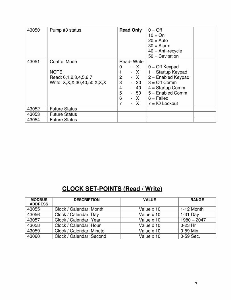
7
43050 Pump #3 status Read Only 0 = Off 10 = On 20 = Auto 30 = Alarm 40 = Anti-recycle 50 = Cavitation
43051 Control Mode NOTE: Read: 0,1,2,3,4,5,6,7 Write: X,X,X,30,40,50,X,X,X
Read- Write 0 - X 1 - X 2 - X 3 - 30 4 - 40 5 - 50 6 - X 7 - X
0 = Off Keypad 1 = Startup Keypad 2 = Enabled Keypad 3 = Off Comm 4 = Startup Comm 5 = Enabled Comm 6 = Failed 7 = IO Lockout
43052 Future Status 43053 Future Status 43054 Future Status
CLOCK SET-POINTS (Read / Write)
MODBUS ADDRESS
DESCRIPTION VALUE RANGE
43055 Clock / Calendar: Month Value x 10 1-12 Month 43056 Clock / Calendar: Day Value x 10 1-31 Day 43057 Clock / Calendar: Year Value x 10 1980 – 2047 43058 Clock / Calendar: Hour Value x 10 0-23 Hr
43059 Clock / Calendar: Minute Value x 10 0-59 Min. 43060 Clock / Calendar: Second Value x 10 0-59 Sec.

8
SET-POINTS (Read / Write) and (Read Only)
MODBUS ADDRESS
DESCRIPTION TYPE VALUE RANGE
43061 Program version Read Only Value x 10 43062 High level shutdown delay Read/Write Value x 10 0-10 Sec. 43063 High level alarm Read/Write Value x 10 50-100% 43064 High level alarm delay Read/Write Value x 10 0-10 Sec. 43065 Low level alarm Read/Write Value x 10 0-50% 43066 Low level alarm delay Read/Write Value x 10 0-10 Sec. 43067 Low level shutdown Read/Write Value x 10 0-50% 43068 Low level shutdown delay Read/Write Value x 10 0-10 Sec. 43069 Liquid transfer on Read/Write Value x 10 50-100% 43070 Liquid transfer on delay Read/Write Value x 10 0-10 Sec. 43071 Liquid transfer off Read/Write Value x 10 50-100% 43072 Liquid transfer off delay Read/Write Value x 10 0-10 Sec. 43073 Level control set-point #1 Read/Write Value x 10 0-100% 43074 Level control set-point #1 delay Read/Write Value x 10 0-10 Sec. 43075 Dead band #1 Read/Write Value x 10 0.0-2% 43076 Proportional #1 Read/Write Value x 10 0 – 256 43077 Level control set-point #2 Read/Write Value x 10 0-100% 43078 Level control set-point #2 delay Read/Write Value x 10 0-10 Sec. 43079 Dead band #2 Read/Write Value x 10 0.0-2% 43080 Proportional #2 Read/Write Value x 10 0 – 256 43081 Micro Start Mode Read/Write 0 = Startup
10 = Normal
43082 Level Control Set-point Adjust Read/Write Value x 10 0-50% 43083 Standby Pump Read/Write 10 = 1
20 = 2 30 = 3
43084 Pump cavitations off time Read/Write Value x 10 0-10 Min. 43085 Power fail restart Read/Write 0 = Stay off
10 = Time limit 20 = Always
43086 Low diff press pump stop Read Only Value x 10 0-200 PSI 43087 Low diff press pump stop delay Read Only Value x 10 0-30 Sec. 43088 #1 auxiliary contact delay Read/Write Value x 10 0-10 Sec. 43089 #2 auxiliary contact delay Read/Write Value x 10 0-10 Sec. 43090 #3 auxiliary contact delay Read/Write Value x 10 0-10 Sec. 43091 #1 oil level switch delay Read/Write Value x 10 0-10 Sec. 43092 #2 oil level switch delay Read/Write Value x 10 0-10 Sec.
43093 #3 oil level switch delay Read/Write Value x 10 0-10 Sec. 43094 #1 anti-recycle delay Read/Write Value x 10 0-120 Sec. 43095 #2 anti-recycle delay Read/Write Value x 10 0-120 Sec.

9
43096 #3 anti-recycle delay Read/Write Value x 10 0-120 Sec. MODBUS ADDRESS
DESCRIPTION TYPE VALUE RANGE
43097 High amps shutdown #1 Read Only Value x 10 0-100A 43098 High amps shutdown #1 delay Read Only Value x 10 0-10 Sec. 43099 High amps alarm #1 Read/Write Value x 10 0-100A
43100 High amps alarm #1 delay Read/Write Value x 10 0-10 Sec. 43101 Low amps alarm #1 Read/Write Value x 10 0-100A 43102 Low amps alarm #1 delay Read/Write Value x 10 0-30 Sec. 43103 Low amps shutdown #1 Read Only Value x 10 0-100A 43104 Low amps shutdown #1 delay Read Only Value x 10 0-30 Sec. 43105 High amps shutdown #2 Read Only Value x 10 0-100A
43106 High amps shutdown #2 delay Read Only Value x 10 0-10 Sec. 43107 High amps alarm #2 Read/Write Value x 10 0-100A 43108 High amps alarm #2 delay Read/Write Value x 10 0-10 Sec. 43109 Low amps alarm #2 Read/Write Value x 10 0-100A 43110 Low amps alarm #2 delay Read/Write Value x 10 0-30 Sec. 43111 Low amps shutdown #2 Read Only Value x 10 0-100A 43112 Low amps shutdown #2 delay Read Only Value x 10 0-30 Sec. 43113 High amps shutdown #3 Read Only Value x 10 0-100A 43114 High amps shutdown #3 delay Read Only Value x 10 0-10 Sec. 43115 High amps alarm #3 Read/Write Value x 10 0-100A 43116 High amps alarm #3 delay Read/Write Value x 10 0-10 Sec. 43117 Low amps alarm #3 Read/Write Value x 10 0-100A 43118 Low amps alarm #3 delay Read/Write Value x 10 0-10 Sec. 43119 Low amps shutdown #3 Read Only Value x 10 0-100A 43120 Low amps shutdown #3 delay Read Only Value x 10 0-10 Sec. 43121 Low amps bypass off Read Only Value x 10 0-100A 43122 Low amps bypass off delay Read Only Value x 10 0-10 Sec. 43123 Low amps bypass on Read Only Value x 10 0-100A 43124 Low amps bypass on delay Read Only Value x 10 0-10 Sec.
43125 Power-fail restart delay Read/Write Value x 10 0-240 Min. 43126 Alarm horn delay Read/Write Value x 10 0-10 Sec. 43127 Screen saver Read Only 0 = Disabled
10 = Enabled
43128 Screen saver delay Read Only Value x 10 0-240 Sec. 43129 Start-up screen Read Only 0 = Disabled
10 = Enabled
43130 # of pumps Read Only 10 = 1 20 = 2 30 = 3
43131 Type of pumps Read Only 0 = Other 10 = Cornell
43132 Vessel level input type Read Only 0 = Probe 10 = Float

10
MODBUS ADDRESS
DESCRIPTION TYPE VALUE RANGE
43133 Liquid feed valve type Read Only 0 = Solenoid 10 = Motorized
43134 # of liquid feed valves Read Only 10 = 1 20 = 2
43135 Security code digit #4 Read Only Value x 10 0-9 43136 Security code digit #3 Read Only Value x 10 0-9 43137 Security code digit #2 Read Only Value x 10 0-9 43138 Security code digit #1 Read Only Value x 10 0-9 43139 Pump #1 mode Read/Write 0 = Auto
10 = On 20 = Off
43140 Pump #2 mode Read/Write 0 = Auto 10 = On 20 = Off
43141 Pump #3 mode Read/Write 0 = Auto 10 = On 20 = Off
43142 Liquid transfer Read Only 0 = Disabled 10 = Enabled
43143 Screen contrast Read Only Value x 10 0-31 43144 Back light delay Read Only Value x 10 0-300 Sec. 43145 Security Read Only 0 = Disabled
10 = Enabled
43146 CT range #1 Read Only 0 = 10 Amps 10 = 30 Amps 20 = 50 Amps 30 = 70 Amps
43147 CT range #2 Read Only 0 = 10 Amps 10 = 30 Amps 20 = 50 Amps 30 = 70 Amps
43148 CT range #3 Read Only 0 = 10 Amps 10 = 30 Amps 20 = 50 Amps 30 = 70 Amps
43149 Initialize set-points Read Only 0 = No 10 = Yes
43150 Level probe adjust (calibrate) Read Only Value x 10 -15% to +15% 43151 Vessel press adjust (cal) Read Only Value x 10 -25G to +25G 43152 Pump disch press adjust (cal) Read Only Value x 10 -25G to +25G 43153 Vessel temp adjust (cal) Read Only Value x 10 -25F to +25F 43154 Motor #1 amps adjust (cal) Read Only Value x 10 -15A to +15A 43155 Motor #2 amps adjust (cal) Read Only Value x 10 -15A to +15A

11
MODBUS ADDRESS
DESCRIPTION TYPE VALUE RANGE
43156 Motor #3 amps adjust (cal) Read Only Value x 10 -15A to +15A 43157 Startup time Read/Write Value x 10 0-120 Min 43158 Remote reset input Read Only 0 = Disabled
10 = Enabled
43159 Vessel temperature Read Only 0 = Disabled 10 = Enabled
43160 Motor #1 run hours digit #1 Read Only Value x 10 0-9 43161 Motor #1 run hours digit #2 Read Only Value x 10 0-9 43162 Motor #1 run hours digit #3 Read Only Value x 10 0-9 43163 Motor #1 run hours digit #4 Read Only Value x 10 0-9 43164 Motor #1 run hours digit #5 Read Only Value x 10 0-9 43165 Motor #1 run hours digit #6 Read Only Value x 10 0-9 43166 Motor #2 run hours digit #1 Read Only Value x 10 0-9 43167 Motor #2 run hours digit #2 Read Only Value x 10 0-9 43168 Motor #2 run hours digit #3 Read Only Value x 10 0-9 43169 Motor #2 run hours digit #4 Read Only Value x 10 0-9 43170 Motor #2 run hours digit #5 Read Only Value x 10 0-9 43171 Motor #2 run hours digit #6 Read Only Value x 10 0-9 43172 Motor #3 run hours digit #1 Read Only Value x 10 0-9
43173 Motor #3 run hours digit #2 Read Only Value x 10 0-9 43174 Motor #3 run hours digit #3 Read Only Value x 10 0-9 43175 Motor #3 run hours digit #4 Read Only Value x 10 0-9 43176 Motor #3 run hours digit #5 Read Only Value x 10 0-9 43177 Motor #3 run hours digit #6 Read Only Value x 10 0-9 43178 Service set-up mode Read Only 0 = Disabled
10 = Enabled
43179 Integral #1 Read/Write Value x 10 0 – 256 43180 Integral #2 Read/Write Value x 10 0 – 256 43181 Liquid feed #1 mode Read Only 0 = Auto
10 = Manual
43182 Liquid feed #2 mode Read Only 0 = Auto 10 = Manual
43183 Liquid feed #1 manual percent Read Only Value x 10 0-100% 43184 Liquid feed #1 manual percent Read Only Value x 10 0-100% 43185 High level shutdown Read Only Value x 10 50-100% 43186 IP address digit #4 Read Only Value x 10 0-255 43187 IP address digit #3 Read Only Value x 10 0-255 43188 IP address digit #2 Read Only Value x 10 0-255 43189 IP address digit #1 Read Only Value x 10 0-255 43190 Subnet mask digit #4 Read Only Value x 10 0-255 43191 Subnet mask digit #3 Read Only Value x 10 0-255 43192 Subnet mask digit #2 Read Only Value x 10 0-255 43193 Subnet mask digit #1 Read Only Value x 10 0-255

12
MODBUS ADDRESS
DESCRIPTION TYPE VALUE RANGE
43194 Slave address Read Only Value x 10 1-99 43195 Baud rate Read Only 0 = 2400
10 = 4800 20 = 9600 30 = 19200
43196 Data bits Read Only 0 = 7 bits 10 = 8 bits
43197 Parity Read Only 0 = Even 10 = Odd 20 = None
43198 Stop bits Read Only 0 = 1 10 = 2
43199 Analog output #1 zero Read Only Value x 10 -1.00 to +1.00
43200 Analog output #1 span Read Only
Value x 10 -1.00 to +1.00
43201 Analog output #2 zero Read Only
Value x 10 -1.00 to +1.00
43202 Analog output #2 span Read Only
Value x 10 -1.00 to +1.00
43203 Analog output #3 zero Read Only Value x 10 -1.00 to +1.00
43204 Analog output #3 span Read Only Value x 10 -1.00 to +1.00
43205 Analog output board Read/Write 0 = Disabled 10 = Enabled
43206 Clear all active alarms Read/Write 0 = No 10 = Yes
43207 Solenoid Off Diff #1 Read/Write Value x 10 1-100%
43208 Solenoid Off Diff #2 Read/Write Value x 10 1-100%
43209 Pump Auto Restart Read/Write 0 = Disabled 10 = Enabled
43210 Pump Ramp Start Read/Write 0 = Disabled 10 = Enabled
43211 Pump Ramp Start Delay Read/Write Value x 10 0-180 Sec.
43212 Analog Dampering Read Only Value x 10 40 - 99
43213 Derivative #1 Read/Write Value x 10 0 – 99
43214 Derivative #2 Read/Write Value x 10 0 – 99

13
MODBUS ADDRESS
DESCRIPTION TYPE VALUE RANGE
43215 Adjustment Delay #1 Read/Write Value x 10 .1–10 Sec.
43216 Adjustment Delay #2 Read/Write Value x 10 .1–10 Sec.
43217-43230
Future
43231 Pump #1 auxiliary shutdown Read Only 0 = Normal 1 = Alarm
43232 Pump #2 auxiliary shutdown Read Only 0 = Normal 1 = Alarm
43233 Pump #3 auxiliary shutdown Read Only 0 = Normal 1 = Alarm
43234 Pump #1 oil level shutdown Read Only 0 = Normal 1 = Alarm
43235 Pump #2 oil level shutdown Read Only 0 = Normal 1 = Alarm
43236 Pump #3 oil level shutdown Read Only 0 = Normal 1 = Alarm
43237 Pump #1 high amps shutdown Read Only 0 = Normal 1 = Alarm
43238 Pump #2 high amps shutdown Read Only 0 = Normal 1 = Alarm
43239 Pump #3 high amps shutdown Read Only 0 = Normal 1 = Alarm
43240 Pump #1 high amps alarm Read Only 0 = Normal 1 = Alarm
43241 Pump #2 high amps alarm Read Only 0 = Normal 1 = Alarm
43242 Pump #3 high amps alarm Read Only 0 = Normal 1 = Alarm
43243 Pump #1 low amps alarm Read Only 0 = Normal 1 = Alarm
43244 Pump #2 low amps alarm Read Only 0 = Normal 1 = Alarm
43245 Pump #3 low amps alarm Read Only 0 = Normal 1 = Alarm
43246 Pump #1 low amps shutdown Read Only 0 = Normal 1 = Alarm
43247 Pump #2 low amps shutdown Read Only 0 = Normal 1 = Alarm
43248 Pump #3 low amps shutdown Read Only 0 = Normal 1 = Alarm
43249 Pump #1 min amps startup Read Only 0 = Normal 1 = Alarm

14
MODBUS ADDRESS
DESCRIPTION TYPE VALUE RANGE
43250 Pump #2 min amps startup Read Only 0 = Normal 1 = Alarm
43251 Pump #3 min amps startup Read Only 0 = Normal 1 = Alarm
43252 High vessel level shutdown Read Only 0 = Normal 1 = Alarm
43253 High vessel level alarm Read Only 0 = Normal 1 = Alarm
43254 Low vessel level alarm Read Only 0 = Normal 1 = Alarm
43255 Low vessel level shutdown Read Only 0 = Normal 1 = Alarm
43256 Complete pump fail shutdown Read Only 0 = Normal 1 = Alarm
43257 Pump #1 cavitation shutdown Read Only 0 = Normal 1 = Alarm
43258 Pump #2 cavitation shutdown Read Only 0 = Normal 1 = Alarm
43259 Pump #3 cavitation shutdown Read Only 0 = Normal 1 = Alarm
43260 Pump #1 running shutdown Read Only 0 = Normal 1 = Alarm
43261 Pump #2 running shutdown Read Only 0 = Normal 1 = Alarm
43262 Pump #3 running shutdown Read Only 0 = Normal 1 = Alarm
43263 Analog output comm failure Read Only 0 = Normal 1 = Alarm
JUMPER TABLE:
CPU Board J7 X Not Installed J8 X Not Installed
JP10 X (1-2) (4-6) NOTE: X indicates recommended jumper settings

15
MODBUS Ethernet
Connection
MODBUS RS-485
Connection Using
RS-232 to RS-485 Converter
NOTE: RS-485 port not active