Embed Size (px)
Citation preview

Air F low Meter
A superb way to save energy when usingcompressed air or nitrogen.
CP-PC-1474E
www.azbil .com
Please read the "Terms and Conditions" from the following URL before ordering or use:
http://www.azbil.com/products/bi/order.html
1-12-2 Kawana, FujisawaKanagawa 251-8522 JapanURL: http://www.azbil.com
1st Edition : Issued in Feb. 2008-SK9th Edition: Issued in Sep. 2013-AZ CP-PC-1474E
[Notice] Specifications are subject to change without notice. No part of this publication may be reproduced or duplicated
without the prior written permission of Azbil Corporation.
Yamatake Corporation changed its name to Azbil Corporation on April 1, 2012.
Other product names, model numbers and company names may be trademarks of the respective company.
(10)

Features of the Air Flow MeterFeatures of the Air Flow Meter
21
Energy Management SystemEnescope,PREXON
Converter
Converter
RS-485LAN
LAN
RS-485
¥$
Cost management for production line or whole departmentKnowing the total flow quantity and cost for an area, and budgeting by area, is sure to increase cost consciousness and enable measurement of cost reduction efforts.
Detecting air leakageSubstantial reduction of air leakage by determining the leakage quantity — generally said to be around 30% — and repairing the leaks.
Read the instantaneous �ow rate from the �owmeter.
Plot the instantaneous �ow rate using a PC.
Leakage check method
1
2
Instantaneous �ow rate
Line stop
Leakage quantity
Supply of appropriate quantities
Since the air quantity used by equipment can be checked to know if it is appropriate, waste can be reduced by restricting the air supply to an appropriate quantity.
1/50 of �ow rate range
1/10 of �ow rate range0 Flow rate range × 2-30% of �ow rate range Flow rate range
The measurement unit can be dismounted and replaced for easy maintenance at the application site without disconnecting the pipes.(Pipe sizes 25/40/50A only)
■ Practical measurement range of 50:1 and extended range function providing up to 2 times the standard range are useful for detecting air leakage
■ Reverse flow detection function
■ Use a single MCF for flow in various directions ■ Easy maintenance without removal from the piping
A dedicated air/nitrogen mass flowmeter, indispensable for cutting compressor energy use.
The display unit can rotate more than 90° counterclockwise and more than 180° clockwise.
■ The MCF series is a mass flowmeter.
MCF ±3 % FS accuracy range
Convent ional model
±10 % rdg. (approx.) ±6 % FS (guideline)
For ease of use and ease of selection,models in a broad range from small to large are available.
Pipe size: 8/15/25/40/50A Range: 200/500/1000/3000 /6000/12000 L/min
■ Model lineup meets a variety of application requirementsUseful for loop piping. Reverse flow detection and forward-reverse flow integration functions are provided.
・Reverse flow measurement range is up to 30% of forward flow rate measurement range.
CW 180°
CW 90°
CCW 90°
No f low
When gas f lows
FLOW
H o w m u c h i s u s e d i n t h i s s e c t i o n ?
Downstream temperature sensor (Rd)Upstream temperature sensor (Ru)
Diaphragm
Ambient temperature sensor (Rr)
Heater (Rh)0.5mm
1.7 mm
A
Silicon chip
Diaphragm
Cavity
RdRuRr Rh
Section A-A’
Silicon chip
FLOW
A’
Thermal mass flow measurement using Azbil Corporation's Micro Flow (μF) sensor ensures correct measurement even if gas temperature or pressure changes.
Sensor structure Measurement Principle
■ Battery drive model line up
Application examples
Temperature prof i le
Temperature prof i le
Model No.
Gas types
Flow rate range[L/min(normal)]*1
Reverse �ow range[L/min(normal)]*2
Extended range[L/min(normal)]*3
Accuracy guaranteed
�ow rate range[L/min(normal)]
Measurement accuracy
Smallest detectable �ow rate[L/min(normal)]
Display resolution[L/min(normal)]
Temperature
Storage temperature
Humidity
Pipe size
Connection type
Body material
O-ring material
Case material
Operating pressure range
Pressure resistance
Mounting orientation
Rated voltage
Sampling cycle/ response time
Output signal ("D01" 4 to 20 mA model only)*4
Event output ("D01" 4 to 20 mA model only)*4
Event function ("D01" 4 to 20 mA model only)*4
Communications("D10" RS485 Communication model only)
Electrical connection
Display
Protective structure
Standards compliance
Weight
MCF0080
0 to 200
-60
400
4 to 200
2
1
8A(1/4B)
400 g
MCF0150
0 to 500
-150
1000
10 to 500
5
1
15A(1/2B)
400 g
MCF0250
0 to 3000
-900
6000
60 to 3000
30
5
25A(1B)
500 g
Air/nitrogen. (Note that gas must be dry, without corrosive components such as chlorine, sulfur and acid. It must also be clean, without dust or oil mist.)
± 3% FS
-10 to +60 ℃ (without freezing)
-20 to +70 ℃ (without freezing)
0 to 90 % RH (without condensation)
MCF□□□□□R: Rc thread MCF□□□□□G : G thread
Aluminum alloy
MCF□□□□A : H-NBR MCF□□□□F : FKM
Denatured PPO
-0.07 to +1.0 MPa
1.5 MPa
・Horizontal (flow: left → right, right → left) ・Vertical (flow: up → down, down → up)
24V DC, 120 mA max.
50 ms to 1.5 s max. (time for 95 % of response to 0 →100 % FS step input)
4 to 20 mA, allowable load resistance 300 Ω max.
One open collector output (rating 30V DC, 50 mA), with output type selectable from event function.
Selectable from pulse output for integration*5, instantaneous flow rate high/low limit alarm, integration count up/down, or alarm output.
RS-485 Communications (3-wire system), MODBUS Protocol Transmission speed 19200 bps max.
PA5 Series VA connector (4 pins)
7-segment, 5-digit display changeable between instantaneous flow rate, integrated (cumulative) flow, and cost.
IP65. (Rating is based on JIS C 0920 and IEC529. For purposes of installation indoors, device is waterproof and dustproof.)
CE marked : EN61326-2-3 : 2006
MCF0400
0 to 6000
-1800
12000
120 to 6000
60
10
40A(1 1/2B)
700 g
MCF0500
0 to 12000
-3600
24000
240 to 12000
120
10
50A(2B)
1100 g
MCF0151
0 to 1000
-300
2000
20 to 1000
10
2
15A(1/2B)
400 g
MCF
Model No.MCF0080MCF0150
Pulse weight (L/pulse)10, 100, 100010, 100, 1000
Notes: *1. The unit L/min (normal) refers to the volumetric flow rate adjusted for 0℃, 101.325 kPa. *2. Flow is displayed as a negative value even if the setting is not changed.*3. Indication value and integrated pulse output can be displayed and output even if the setting is not changed, but 4–20 mA output requires a change of the span setting.*4. For RS485 communication models, there is no terminal output. *5. Integrated pulse output specifications (selectable by settings) ・ Pulse width: 50 ms, 250 ms, 500 ms ・ Pulse weight:
Note: Types other than the above are available. Please contact Yamatake Corporation.
*Note 1 Measurement modules in models MCF008, 015 (pipe sizes 8A, 15A) cannot be replaced.
008001500151025004000500
Material
A
F
Connection
RG
Gas type
N
Option 1
0
Option 3
0KDLYX
Option 2
0
Description
Air flowmeter MCF
8A(1/4B)・200L/min
15A(1/2B)・500L/min15A(1/2B)・1000L/min25A(1B)・3000L/min40A(1 1/2B)・6000L/min50A(2B)・12000L/minBody : aluminum alloy O-ring:H-NBR
Rc thread
G thread
Air/Nitrogen
24V DC / 4--20 mA output / one open collector
24V DC / RS-485 communication / none outputs*1
(None)
(None)
(None)
Antisulfidization*2
Inspection data provided
Antisulfidization + inspection data*2
Traceability certificate
Antisulfidization + traceability Certificate*2
Product version
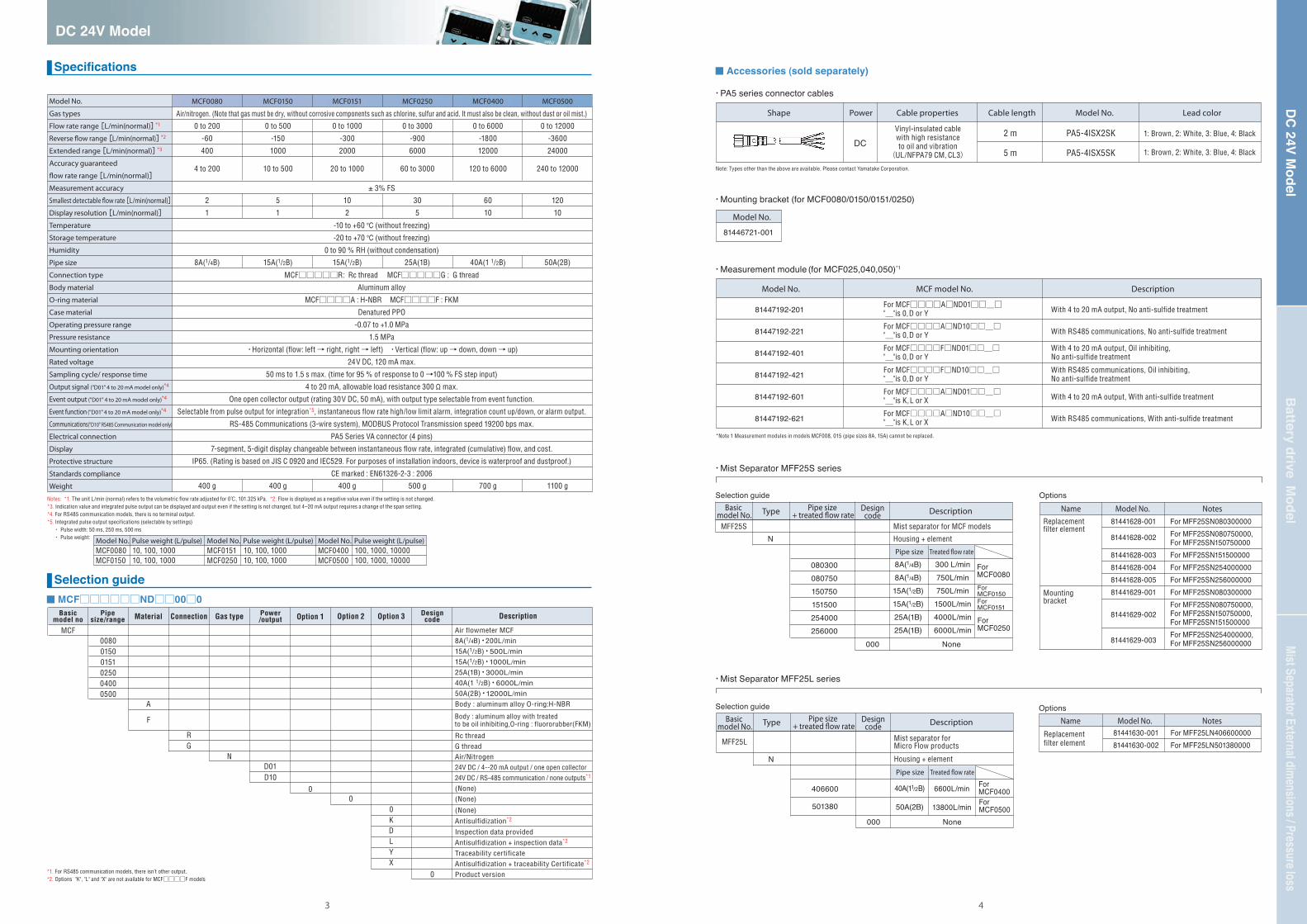
■ Specifications
■ MCF□□□□□□ND□□00□0
・PA5 series connector cables
Model No.MCF0151MCF0250
Pulse weight (L/pulse)10, 100, 100010, 100, 1000
Model No.MCF0400MCF0500
Pulse weight (L/pulse)100, 1000, 10000100, 1000, 10000
2 m
5 m
PA5-4ISX2SK
PA5-4ISX5SK
1: Brown, 2: White, 3: Blue, 4: Black
1: Brown, 2: White, 3: Blue, 4: Black
Shape Power Cable lengthCable properties
Vinyl-insulated cablewith high resistanceto oil and vibration
(UL/NFPA79 CM, CL3)
Model No. Lead color
DC
・Measurement module (for MCF025,040,050) *1
With 4 to 20 mA output, No anti-sulfide treatment
With RS485 communications, No anti-sulfide treatment
With 4 to 20 mA output, With anti-sulfide treatment
With RS485 communications, With anti-sulfide treatment
81447192-201
81447192-221
81447192-401
81447192-421
81447192-601
81447192-621
Model No. MCF model No.
For MCF□□□□A□ND01□□_□"_"is 0,D or Y
For MCF□□□□A□ND10□□_□"_"is 0,D or Y
For MCF□□□□F□ND01□□_□"_"is 0,D or Y
For MCF□□□□F□ND10□□_□"_"is 0,D or Y
With RS485 communications, Oil inhibiting,No anti-sulfide treatment
With 4 to 20 mA output, Oil inhibiting, No anti-sulfide treatment
For MCF□□□□A□ND01□□_□"_"is K,L or X
For MCF□□□□A□ND10□□_□"_"is K,L or X
Description
Basicmodel no
Designcode
0
Power/output
D01D10
Pipesize/range
■ Selection guide
Body : aluminum alloy with treated to be oil inhibiting,O-ring : fluororubber(FKM)
*1. For RS485 communication models, there isn’t other output. *2. Options "K", "L" and "X" are not available for MCF□□□□F models
DC 24V Model
43
DC
24V Model
Battery drive Model
Mist Separator External dimensions / Pressure loss
・Mounting bracket (for MCF0080/0150/0151/0250)
■ Accessories (sold separately)
・Mist Separator MFF25S series
Selection guide Options
81446721-001
Model No.
MFF25S
N
080300080750150750151500254000256000
000
Description
Pipe size Treated �ow rate
Mist separator for MCF models
Housing + element
Name NotesModel No.81441628-001
81441628-002
81441628-00381441628-00481441628-00581441629-001
81441629-002
81441629-003
Replacement filter element
Mounting bracket
For MFF25SN080300000For MFF25SN080750000, For MFF25SN150750000For MFF25SN151500000For MFF25SN254000000For MFF25SN256000000For MFF25SN080300000For MFF25SN080750000,For MFF25SN150750000,For MFF25SN151500000For MFF25SN254000000,For MFF25SN256000000
81441630-00181441630-002
For MFF25LN406600000For MFF25LN501380000
・Mist Separator MFF25L series
For MCF0080For MCF0150For MCF0151
For MCF0250
None
8A(1/4B)8A(1/4B)15A(1/2B)15A(1/2B)25A(1B)25A(1B)
300 L/min750L/min750L/min1500L/min4000L/min6000L/min
Pipe size + treated �ow rate
Designcode
Basic model No. Type
Selection guide
MFF25L
N
406600
501380
000
Description
Pipe size Treated �ow rate
Mist separator for Micro Flow products
Housing + element
For MCF0400For MCF0500
None
40A(11/2B)
50A(2B)
6600L/min
13800L/min
Pipe size + treated �ow rate
Designcode
Basic model No. Type
OptionsName NotesModel No.
Replacement filter element

DC 24V Model
65
DC
24V Model
Battery drive Model
Mist Separator External dimensions / Pressure loss
■ External dimensions (Unit: mm)
■ Wiring pin assignment
■ Wiring example
MCF0080 MCF0150 / MCF0151
MCF0250 MCF0400
PA5 cable with VA connector (optional)
PA5 cable with VA connector (optional)
PA5 cable with VA connector (optional)
PA5 cable with VA connector (optional)
VA connector (M12)
VA connector (M12)VA connector (M12)
VA connector (M12)
Rc or G 1/4 (2),thread depth 11
Rc or G 1/2 (2),thread depth 15
81446721-001 mounting bracket(optional)
81446721-001 mounting bracket(optional)
81446721-001 mounting bracket(optional)
(90)
(4.5) (4.5)
(78)
(90)
(78)
75 75
4824
4824
23.5 23.5
47 47
Rc or G 1(2),thread depth 19.1
Rc or G 11/2(2),thread depth 21.4
23.5
47
3060
(75)
65.
8
79.8
93.8
65.
8
34(46.
5)
(46.
5)
(8)
(60.
5)
(74.
5)
(8)
(8)
27
13.5
48
90 100
24
6130.5
27
13.5
34
1727
13.5
15
34
15
48
23.5
62
30
(63)
(75)
(63)
(4.5)
(90)
(78)
(75)
(63)
(for mounting)M4 screws (2), thread depth 7
(for mounting)M4 screws (2), thread depth 7
(for mounting)M5 screws (2), thread depth 7
(for mounting)
M4 screws (2), thread depth 7
MCF side Pin assignment
(male)Connector pin No., PA5 lead color, and signal
1: Brown・・・・V+: 24 Vdc2: White・・・・I+: 4 to 20 mA output3: Blue・・・・ COM4: Black・・・・EV: Event output
Connector pin No., PA5 lead color, and signal
1: Brown・・・・V+: DC24V2: White・・・・ DB: RS4853: Blue・・・・・COM / SG4: Black・・・・ DA: RS485
PA5 side with VA connectorPin assignment
(female)
MCF side Pin assignment
(male)
PA5 side with VA connectorPin assignment
(female)
PA5 cable with VA connector (optional)
VA connector (M12)
MCF0500
Rc or G 2 (2),thread depth 25.7
106.
8
(87.
5)
110
6130.5
34
17
37.5
75
75
37.5
(for mounting)
M5 screws (2), thread depth 7
■ MCF□□□□□□ND□□00□□: DC 24V Model ■ Mounting bracket, (for MCF0080/0150/0151/0250)
81446721-001
Material:SUS304
A, 4 locations
5.5
5012
.512
.5
4~4.5 dia hole
18276
3
75
6
15
6
48
78
90
4.5
A6.5
(R)
1
2
3
4
V
I
COM
EV
Instantaneous flow rate output4 to 20mA
Allowable load resistance (up to 300 )
Load
22.8 to 25.2V DC
30V DC or less30V DC, 50 mA or less
External connection exampleInternal circuit
Terminating resistor
Shield
Master station
MCF(Slave station)
DA
DB
SG
DA
DBCOM
FG
FG
V+
DA
DB
SG
FG
Slave station
4
2
3
1
Terminating resistor
External connection exampleInternal circuit
Shield
22.8 to 25.2V DC
(1)MCF□□□□□□ND01□□□□ 4-20mA, open collector output
(2)MCF□□□□□□ND10□□□□ (RS-485)
(1)MCF□□□□□□ND01□□□□ 4-20mA, open collector output
(2)MCF□□□□□□ND10□□□□ (RS-485)
Connect terminating resistors of 150 ±5%, 1/2 W min. at each end of the transmission line.The FG grounding must not be made at the both shielded wire ends but only at one location.Azbil Corporation's CMC10L001A000 can beused as a converter of the host station.
・
・
・

Battery drive Model
87
DC
24V Model
Battery drive Model
Mist Separator External dimensions / Pressure loss
Model No.
Gas types
Flow rate range[L/min(normal)]*1
Accuracy guaranteed �ow rate range[L/min(normal)]
Measurement accuracy
Smallest detectable �ow rate[L/min(normal)]
Display resolution[L/min(normal)]
Temperature
Storage temperature
Humidity
Pipe size
Connection type
Body material
O-ring material
Case material
Operating pressure range
Pressure resistance
Mounting orientation
Power supply
Sampling cycle/ response time
Output signal
Event output
Event function
Electrical connection
Display
Protective structure
Weight
Air/nitrogen (Note that gas must be dry, without corrosive components such as chlorine, sulfur and acid. It must also be clean, without dust or oil mist.)
± 3% FS
-10 to +60 ℃ (without freezing)
-10 to +60 ℃ (without freezing)
0 to 90 % RH (without condensation)
MCF□□□□□R: Rc thread MCF□□□□□G: G thread
Aluminum alloy
H-NBR
Denatured PPO
-0.07 to +1.0 MPa
1.5 MPa
・Horizontal (flow: left → right, right → left) ・Vertical (flow: up → down, down → up)
4AA alkaline batteries *2
1s / 30s max
no signal output
Two open collector output (rating 30V DC, 50 mA) ① Event ② Battery alarm
Selectable from pulse output for integration*2, instantaneous flow rate high/low limit alarm, integration count up/down or alarm output.
PA5 Series VA connector (4 pins)
7-segment, 5-digit display changeable between instantaneous flow rate, integrated (cumulative) flow, and cost.
IP65 (Rating is based on JIS C 0920 and IEC529. For purposes of installation indoors, device is waterproof and dustproof.)
MCF0080
0 to 200
4 to 200
2
1
8A(1/4B)
400 g
MCF0150
0 to 500
10 to 500
5
1
15A(1/2B)
400 g
MCF0250
0 to 3000
60 to 3000
30
5
25A(1B)
500 g
MCF0400
0 to 6000
120 to 6000
60
10
40A(1 1/2B)
700 g
MCF0500
0 to 12000
240 to 12000
120
10
50A(2B)
1100 g
MCF0151
0 to 1000
20 to 1000
10
2
15A(1/2B)
400 g
MCF
Notes: *1. The unit L/min (normal) refers to the volumetric flow rate adjusted for 0℃, 101.325 kPa. *2. The 4AA batteries included in the battery box kit are for a test run.*3. Integrated pulse output specifications (selectable by settings) ・ Pulse width: 125ms ・ Pulse weight:
Notes: *1. Use the model with a ‘T ’ at the end.
008001500151025004000500
Material
A
Connection
RG
Gas type
NB01
Option 1
0B
Option 3
0DY
Option 2
0
Description
Air flowmeter MCF
8A(1/4B)・200L/min
15A(1/2B)・500L/min15A(1/2B)・1000L/min25A(1B)・3000L/min40A(1 1/2B)・6000L/min50A(2B)・12000L/minBody : aluminum alloy, O-ring:H-NBR
Rc thread
G thread
Air/Nitrogen
Battery drive
(None)
(None)
(None)
Inspection data provided
Traceability certificate
Product version
■ Specifications
■ MCF□□□□A□NB010B□0Basic
model noDesigncode
Power/output
Pipesize/range
■ Selection guide・Mist Separator MFF25S series
Selection guide Options
MFF25S
N
080300080750150750151500254000256000
000
Description
Pipe size Treated �ow rate
Mist separator for MCF models
Housing + element
Name NotesModel No.81441628-001
81441628-002
81441628-00381441628-00481441628-00581441629-001
81441629-002
81441629-003
Replacement filter element
Mounting bracket
For MFF25SN080300000For MFF25SN080750000, For MFF25SN150750000For MFF25SN151500000For MFF25SN254000000For MFF25SN256000000For MFF25SN080300000For MFF25SN080750000,For MFF25SN150750000,For MFF25SN151500000For MFF25SN254000000,For MFF25SN256000000
81441630-00181441630-002
For MFF25LN406600000For MFF25LN501380000
・Mist Separator MFF25L series
For MCF0080
For MCF0150For MCF0151
For MCF0250
None
8A(1/4B)8A(1/4B)15A(1/2B)15A(1/2B)25A(1B)25A(1B)
300 L/min
750L/min
750L/min
1500L/min
4000L/min
6000L/min
Pipe size + treated �ow rate
Designcode
Basic model No. Type
Selection guide
MFF25L
N
406600
501380
000
Description
Pipe size Treated �ow rate
Mist separator for Micro Flow products
Housing + element
For MCF0400
For MCF0500
None
40A(11/2B)
50A(2B)
6600L/min
13800L/min
Pipe size + treated �ow rate
Designcode
Basic model No. Type
OptionsName NotesModel No.
Replacement filter element
■ Accessories, electrical connection
2m
3m
5m
PA5-4ISB2SK
PA5-4ISB3SK
PA5-4ISB5SK
Shape Cable lengthCable properties
Vinyl-insulated cablewith high resistanceto oil and vibration
(UL/NFPA79 CM, CL3)
Model No.
Note: Types other than the above are available. Please contact Yamatake Corporation.
・Cable for battery box to output
2m
5m
PA5-4ISX2SK
PA5-4ISX5SK
1: Brown, 2: White, 3: Blue, 4: Black
1: Brown, 2: White, 3: Blue, 4: Black
Shape Cable lengthCable properties
Vinyl-insulated cablewith high resistanceto oil and vibration
(UL/NFPA79 CM, CL3)
Model No. Lead color
Cable for MCF series to battery box kitThe cable included in MCF series (cable length: 500mm)
Cable for battery box to output (sold separately)
●Battery drive counter(Kimmon)KDC811T *1
SpecificationsInput: Pulse width:Power Supply: Mount: Profective:Weight:
PulseMore than 80msLitium batteryWall mountedStructure: IP×3250g
MCF series
Battery box kit
・MCF series to battery box kit MCF□□□□□□NB010B□0
・Measurement module
Battery drive model, No anti-sulfide treatment81447192-241
Model No. MCF model No.
For MCF□□□□A□NB01□□_□"_"is 0,D or Y
DescriptionModel No.MCF0080MCF0150
Pulse weight (L/pulse)10, 100, 100010, 100, 1000
Model No.MCF0151MCF0250
Pulse weight (L/pulse)10, 100, 100010, 100, 1000
Model No.MCF0400MCF0500
Pulse weight (L/pulse)100, 1000, 10000100, 1000, 10000

Battery drive ModelD
C 24V M
odelBattery drive M
odelMist Separator External dimensions / Pressure loss
MCF0080 MCF0150/0151
MCF0250 MCF0400
81446721-001 mounting bracket(optional)
81446721-001 mounting bracket(optional)
(90)
(4.5) (4.5)
(78)(90)(78)
75 75
48
24
48
24
23.5 23.5
47 47
23.5
47
30
60
(75)
65.8
79.8 93
.8
65.8
34(46
.5)
(46
.5)
(8)
(60
.5)
(74
.5)
(8)
(8)
27
13.5
M4 screws (2), thread depth 7(for mounting)
M5 screws (2), thread depth 7(for mounting)
48
90 100
24
6130.5
27
13.5
34
1727
13.5
15
34
15
48
23.5
62
30
(63)
(75)
(63)
(4.5)
(90)
(78)
(75)
(63)
VA connector (M12)VA connector (M12)
VA connector (M12)VA connector (M12)
■ MCF□□□□A□NB010B□0: Battery drive Model
MCF0500
106.
8
(87
.5)
M5 screws (2), thread depth 7(for mounting)
110
6130.5
34
17
37.5
75
75
37.5
VA connector (M12)
Rc or G 1/4 (2),thread depth 11
Rc or G 1/2 (2),thread depth 15
Rc or G 1(2),thread depth 19.1
Rc or G 11/2(2),thread depth 21.4
Rc or G 2 (2),thread depth 25.7
■ Battery box kit
■ Cable for MCF series to battery box kit ■ U-bolts included in MCF series are for mounting the Battery box kit.
(1)MCF□□□□A□NB010B□0 Pulse, Battery alarm output
■ Wiring pin assignment ■ Wiring example
MCF side Pin assignment
(male)
Connector pin No., PA5 lead color, and signal
1: Brown・・・None
2: White・・・AL: Battery Alarm output
3: Blue・・・・COM
4: Black・・・EV: Event output
PA5 side with VA connectorPin assignment
(female)
1
2
3
4
Externalconnection example
internalcircuit
30V DC or less
Load
30V DC,50 mA or lessCOM
EV
AL
Load
=MCF side
=Battery box kit side
Female
Male
500+5%0 C
B A
U-bolts
Hexagonal nut2×M6
5 0.4
40.2
10.5
25.2
44
15.5
9
45°45°
M12
M12×1
φ14
12.9
φ12
φ14
φ12
The 4AA batteries included in the battery box kit for a test ran
for MCF0500for MCF0400for MCF0250for MCF0150/0151for MCF0080Model
8068493627B
3025251815C
705741
29.521A
VA connect for output(optional)
VA connector for MCF13.313.3
27.2
37.7
12.2
26.6
49.9
67.7
31.6
114.
8
31.7
18.2
4.2
99
11610283.2
80.2
80
6.6
■ External dimensions (Unit: mm)
81446721-001 mounting bracket(optional)
M4 screws (2), thread depth 7(for mounting)
M4 screws (2), thread depth 7(for mounting)
1 09
DC
24V Model
Battery drive Model
Mist Separator External dimensions / Pressure loss
1 21 1
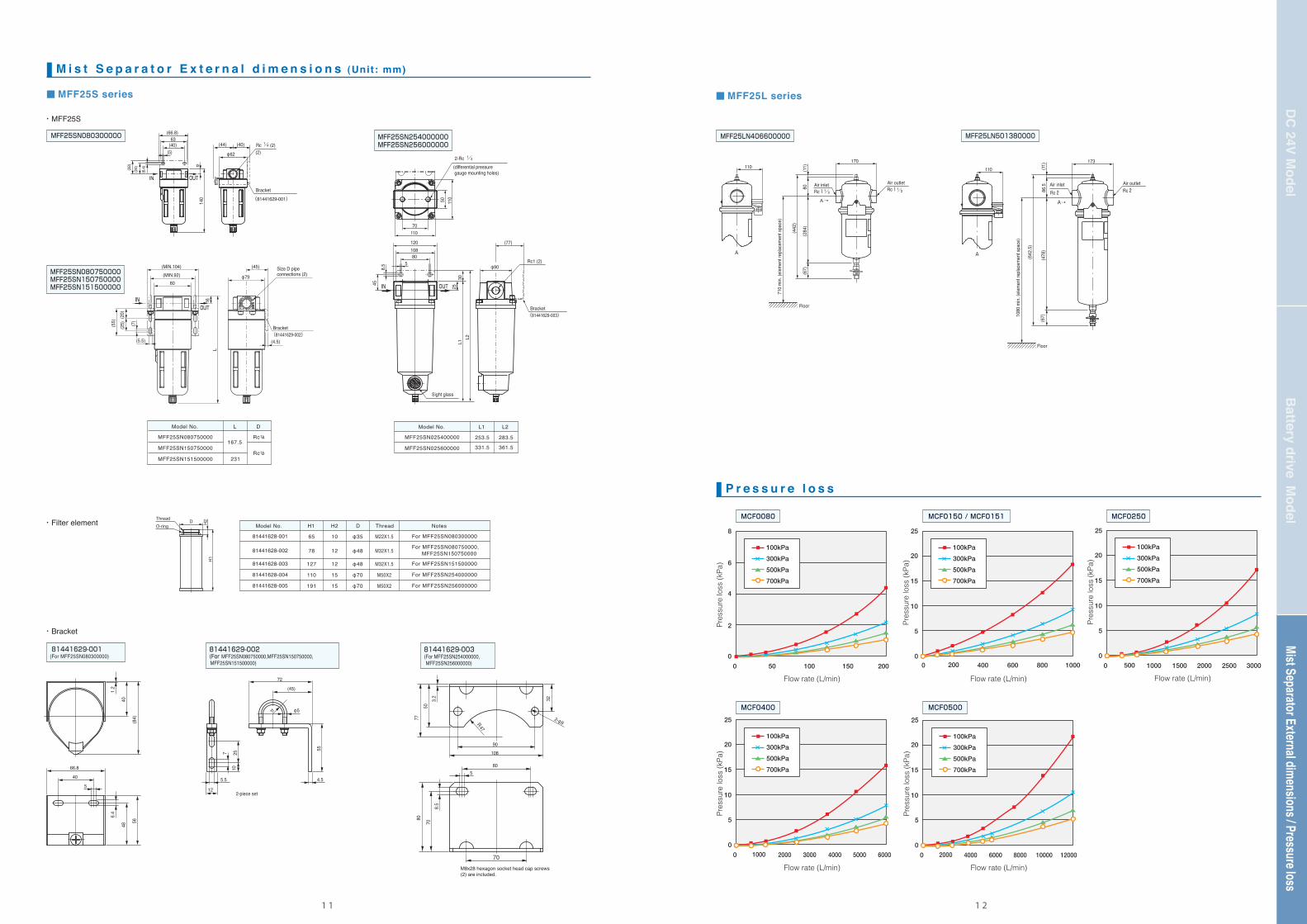
■ P r e s s u r e l o s s
8
6
4
2
0
0 50 100 150 200
Flow rate (L/min)
Pre
ssur
e lo
ss (
kPa)
100kPa
300kPa
500kPa
700kPa
25
20
15
10
5
0
Flow rate (L/min)
Pre
ssur
e lo
ss (
kPa)
100kPa
300kPa
500kPa
700kPa
25
20
15
10
5
0
0 1000 2000 3000 4000 5000 6000
Flow rate (L/min)
Pre
ssur
e lo
ss (
kPa)
100kPa
300kPa
500kPa
700kPa
25
20
15
10
5
0
0 500 1000 1500 2000 30002500
Flow rate (L/min)
Pre
ssur
e lo
ss (
kPa)
100kPa
300kPa
500kPa
700kPa
25
20
15
10
5
0
0 2000 4000 6000 8000 10000 12000
Flow rate (L/min)
Pre
ssur
e lo
ss (
kPa)
100kPa
300kPa
500kPa
700kPa
80
80
M8x28 hexagon socket head cap screws (2) are included.
10890
70
70
5
8.5
77
50
323.2
R47
2-φ9
7
5.5
2510
55
4.5
12
(45)
72
11 φ5
1.2
6.4
4048
5
(84)
40
66.8
56
A→
Air inletRc11/2
1/2
Air outlet Rc1
A
Floor
170110
2-piece set80
(11)
(284
)
710
min.
(elem
ent r
eplac
emen
t spa
ce)
(67)
(442
)
1080
min.
(elem
ent r
eplac
emen
t spa
ce)
A→
A
Floor
110
86.5
(478
)(11
) 173
(67)
(642
.5)
Air inlet Rc2
Air outlet Rc2
■ M i s t S e p a r a t o r E x t e r n a l d i m e n s i o n s (Unit: mm)
・Filter element
・Bracket
MFF25SN080300000 MFF25LN406600000 MFF25LN501380000
MFF25SN080750000MFF25SN150750000MFF25SN151500000
81441629-001 (For MFF25SN080300000)
81441629-002 (For MFF25SN080750000,MFF25SN150750000, MFF25SN151500000)
81441629-003 (For MFF25SN254000000, MFF25SN256000000)
MFF25SN254000000MFF25SN256000000
D H2
H1
■ MFF25S series ■ MFF25L series
・MFF25S
110
120 (77)
φ90Rc1 (2)
10880
5
IN OUT
70
50
458.
5
110
30L1
L2
25
OUTIN
(66.8)63
(40)(5)
(6.4
)
(24)(32) 12
140
φ62
(44) (40)
OUT
(55)
(5.5)
(20)
(7)
(25)
80(MIN.92) φ79
(MIN.104) (45)
(2)
IN 16L
(4.5)
ThreadO-ring
Model No. L D
MFF25SN080750000167.5
Rc1/4
MFF25SN150750000Rc1/2
MFF25SN151500000 231
253.5
331.5
283.5
361.5
Model No. L1 L2
MFF25SN025400000
MFF25SN025600000
65
78
127
110
191
10
12
12
15
15
φ35
φ48
φ48
φ70
φ70
M22X1.5
M32X1.5
M32X1.5
M50X2
M50X2
Model No. H1 H2 D Thread Notes
81441628-001
81441628-002
81441628-003
81441628-004
81441628-005
For MFF25SN080300000
For MFF25SN151500000
For MFF25SN254000000
For MFF25SN256000000
Rc (2)
2-Rc (differential pressure gauge mounting holes)
Bracket
(81441629-001)
Bracket
Size D pipeconnections (2)
Sight glass
(81441629-003)
Bracket(81441629-002)
1/4
1/4
For MFF25SN080750000, MFF25SN150750000
0 200 400 600 800 1000
MCF0150 / MCF0151 MCF0250MCF0080
MCF0400 MCF0500

PrecautionsMi
st Se
para
tor E
xtern
al dim
ensio
ns / P
ress
ure l
oss
Batte
ry d
rive
Mod
elD
C 2
4V M
odel
1 41 3
● Precautions for use・Do not use for gases other than air and nitrogen. Doing so might have serious consequences, such as fire or explosion.・Do not use in excess of the operating pressure range. Do not apply a pressure greater than the pressure resistance. Doing so might result in measurement error or damage to this device.・Application of more than 10 times the full-scale flow rate might result in measurement error or damage to this device.・Position the display, which can be rotated up to 270°, in an easy-to-see direction, taking into account the location of the cable and the location of the display.・When changing the output settings, stop the control system equipment first to avoid unexpected operational errors.・Since this device does not have built-in protection against lightning, be sure to provide lightning surge protection for the equipment.・If there is equipment or a device (e.g., electromagnetic lift, high-frequency induction furnace) generating surges nearby, take countermeasures at the surge- generating equipment, and do not run its wiring together with that of the MCF.・Be sure to use within the specified flow rate range. To prevent flow at an excessive rate, use instrumentation with appropriate supply pressure management and install a throttling valve. If the flow rate exceeds 10 times the upper limit of the range, the displayed and output values might be lower than the actual flow rate.
● Precautions for installation and piping・Handle this precision device with much care. Dropping it or subjecting it to impact may result in damage.・To attach this device to a pipe, fix the MCF in place, and then rotate the connecting pipe to the tightening torque specified in the table below.
・ Prevent foreign matter from entering the device. If rust, water droplets, oil mist, or dust in the piping enters the device, measurement error or damage to the device might result. Before installation, thoroughly flush the upstream and downstream piping and check that no foreign matter remains. If there is a possibility of foreign matter entering the device, install an upstream filter, strainer or mist trap capable of eliminating foreign matter 1 μm or greater in diameter, and be sure to periodically inspect and replace the filter.・Use an appropriate amount of sealant on the pipe threads, but do not coat the top two threads. If too much sealant is applied, it might enter the pipe, causing measurement error or damage to this device.・This device can be mounted in any direction. However, if it is mounted on a horizontal pipe with the display in front (in a vertical plane), a measurement error might occur, depending upon the application pressure (see specifications). Also, if the device is mounted on a horizontal pipe with the display facing downward, rust, water droplets, oil mist, or dust in the piping may stick to the sensor, resulting in measurement error or damage.・Do not install near the output of a compressor or in a similar location affected by pulsing flow or drift. Do not install near a check valve that is hunting. Measurement error might result.
● Accuracy and straight pipe length 〈Connection with different size piping, valve or filter〉・Install straight pipes as needed with the lengths given in the table below *1. If a device that is not listed in the table is installed either upstream or downstream,contact Azbil Corporation for the length of the straight pipe section.If reverse flow is also expected, it is necessary to have the same length of straight pipe downstream as upstream.
● Precautions for electric wiring・ Supply electrical power within the specified range.・ Be sure to check that the wiring is correct before turning the power ON. Incorrect wiring can cause damage or malfunction. Do not wire while the power is ON. ・ Do not rotate the connector after it is inserted into the device. If it is rotated, the internal wiring might be twisted and damaged.・ Run the wiring for this device separately from power or high voltage lines (use a separate electrical conduit).
Model No.
MCF0080
MCF0150MCF0151
MCF025
MCF040
MCF050
Pipe size1/4B
1/2B
1B
11/2B
2B
Tightening torque (N・m)
12 to 14
31 to 33
36 to 38
59 to 61
74 to 76
Flow rate (L/min)
Flow rate (L/min)
Flow rate (L/min)
Flow rate (L/min)
Flow rate (L/min)
Flow rate (L/min)
Pre
ssur
e lo
ss (
kPa)
Pre
ssur
e lo
ss (
kPa)
Pre
ssur
e lo
ss (
kPa)
Flow rate[L/min(1 atm.,32℃,75%RH)] Flow rate[L/min(1 atm.,32℃,75%RH)]
Pre
ssur
e lo
ss (
kPa)
Pre
ssur
e lo
ss (
kPa)
Pre
ssur
e lo
ss (
kPa)
Pre
ssur
e lo
ss (
kPa)
Pre
ssur
e lo
ss (
kPa)
■ P r e c a u t i o n s (For details, refer to the user’s manual.)
Straight pipe section for this devicePipe or connected device
For accuracy within productspecification range (±3 % FS)
For accuracy within productspecification range (±3 % FS)
Ball valve (full-bore type full open)
Regulator・for MCF0080
Regulator・For MCF0150/0151/0250/0400/0500
Air filter
Notes: *1. Do not connect a carbon steel pipe for pressure service (JIS G3454) or stainless steel pipe (JIS G3459) that is larger than schedule 40. Doing so might cause a deterioration of accuracy. (If the pipe schedule number is larger, the inner pipe diameter is smaller, resulting in reduced accuracy.)*2. The straight pipe section lengths given in the right-hand columns above are for connection of a filter the same size (internal diameter) as the MCF.
Straight pipe section for this devicePipe or connected device
Location inrelation tothe MCF
Location inrelation tothe MCF
For accuracyof ±5 % FS
For accuracyof ±5 % FS
MFF25S mist separator for MCF0080/0150/0151/0250 *2
MFF25L mist separator for MCF0400/0500 *2
Pipe one size larger in dia. (connected with reducer)
Pipe one size larger in dia.(connected with reducer)
MCF0080 3/8B → 1/4B MCF0150/0151 3/4B → 1/2B MCF0250 1 1/4B → 1B
MCF0500 2 1/2B → 2B
MCF0400 2B → 1 1/2B
Pipe more than one size smaller in dia.(connected with enlarging pipe)
MCF0080 1/8B → 1/4B MCF0150 / 0151 3/8B → 1/2B MCF0250 3/4B → 1B MCF0400 1 1/4B → 1 1/2B
Upstream
Upstream
Upstream
Upstream
Upstream
Upstream
Upstream
Upstream
Downstream
Downstream
Downstream
Downstream
Downstream
Downstream
Upstream
10D
20D
(Not required)
(Not required)
200D
10D
30D
5D
25D
(Not required)
(Not required)
(Not required)
(Not required)
(Not required)
(Not required)
(Not required)
Single elbow
Double elbow
Upstream
DownstreamUpstream
Downstream
10D
(Not required)
10D
(Not required)
(Not required)
(Not required)
10D
(Not required)
5D
10D
5D
5D
5D
20D
(Not required)
(Not required)
(Not required)
(Not required)
(Not required)
5D
(Not required)(Not required)
Pipe more than one size smaller in dia.(connected with enlarging pipe)
MCF0500 1 1/2B → 2B
Upstream
Downstream
25D
5D
10D
5D
Handl ing precaut ions Do not apply more than maximum operating pressure to the air inlet.
0
2
4
6
8
10
12
14
16
18
0 2000 4000 6000 8000 10000
0.20MPaMaximum
operating flow rate line
0.29MPa
0.39MPa
0.49MPa
0.59MPa
0.78MPa
0.88MPa
0.98MPa
0.69MPa
0
2
4
6
8
10
12
14
16
18
0 5000 10000 15000 20000
0.20MPa0.29
MPa
0.39MPa
0.49MPa
0.59MPa
0.69MPa 0.78
MPa
0.88MPa
0.98MPa
■ Mist Separator
・MFF25S ser ies
・MFF25L ser ies
MFF25LN406600000 MFF25LN501380000
0
5
10
15
20
100 200 3000
0
5
10
15
20
1500 300 450 600 750
0
5
10
15
20
1000 2000 3000 40000
0
5
10
15
20
1500 300 450 600 750
0
5
10
15
20
500 1000 15000
0
5
10
15
20
2000 4000 60000
MFF25SN080300000
MFF25SN150750000
MFF25SN254000000 MFF25SN256000000
MFF25SN151500000
MFF25SN080750000
100kPa300kPa500kPa700kPa
100kPa300kPa500kPa700kPa
100kPa300kPa500kPa700kPa
100kPa300kPa500kPa700kPa
100kPa300kPa500kPa700kPa
100kPa300kPa500kPa700kPa
Maximum operating flow rate line


![MCF CP-PC-1474E 8版 表紙 - Techniquip · Kanagawa 251-8522 Japan URL: ... Issued in Feb. 2008-SK 9th Edition: Issued in Sep. 2013-AZ CP-PC-1474E [Notice] ... H-NBR MCF F : FKM](https://img.pdfslide.tips/doc/110x75/5bf2de1609d3f26d518b4e04/mcf-cp-pc-1474e-8-techniquip-kanagawa-251-8522-japan-url-issued.jpg)


![機材仕様書 - JICA - 国際協力機構‚考銘柄① CPC 100、CP CU1、CP GB1 OMICRON [構成] CPC 100、CP CU1、CP GB1 各1 標準付属品: VEHK0622 イーサーネットPC接続ケーブル(1本/台)](https://img.pdfslide.tips/doc/110x75/5ae851f67f8b9a870490a6a4/-jica-cpc-100cp-cu1cp.jpg)