Embed Size (px)
Citation preview
WS9.1-1ANSYS, Inc. Proprietary© 2010 ANSYS, Inc. All rights reserved.
Release 13.0November 2010
Introduction to ANSYSMechanical
Customer Training Material
Workshop 9.1
Parameter Management
Introduction to ANSYS Mechanical
WS9.1-2ANSYS, Inc. Proprietary© 2010 ANSYS, Inc. All rights reserved.
Release 13.0 November 2010
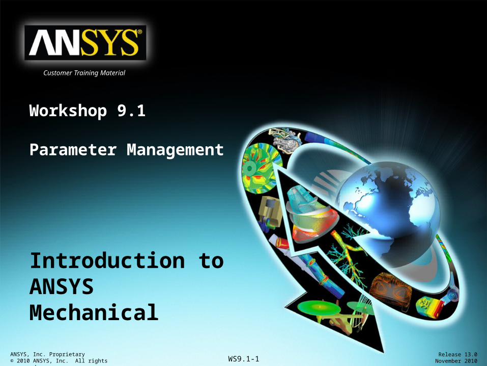
Customer Training MaterialGoals• Goal: – Use the Workbench Parameter Workspace to setup multiple
scenarios to explore structural responses in the bracket shown. – Material thickness will be varied in the gusset with the bracket
thickness held constant then the process will be reversed.
Gusset
Bracket

Introduction to ANSYS Mechanical
WS9.1-3ANSYS, Inc. Proprietary© 2010 ANSYS, Inc. All rights reserved.
Release 13.0 November 2010
Customer Training MaterialProject Schematic• Open the Project page.• From the Units menu verify:– Project units are set to “Metric (kg, mm, s, C, mA, mV).– “Display Values in Project Units” is checked (on).

Introduction to ANSYS Mechanical
WS9.1-4ANSYS, Inc. Proprietary© 2010 ANSYS, Inc. All rights reserved.
Release 13.0 November 2010
Customer Training Material. . . Project Schematic1. From the Toolbox double click
“Static Structural” to create a new system.
2. RMB the geometry cell and “Import Geometry” and browse to “Bracket.stp”.
1.
2.

Introduction to ANSYS Mechanical
WS9.1-5ANSYS, Inc. Proprietary© 2010 ANSYS, Inc. All rights reserved.
Release 13.0 November 2010
Customer Training MaterialPreprocessing
3. Double click the “Model” cell to open the Mechanical application.
4. Set/verify the working unit system:• “Units > Metric (mm, kg, N, s, mV, mA)”.
3.
4.
Introduction to ANSYS Mechanical
WS9.1-6ANSYS, Inc. Proprietary© 2010 ANSYS, Inc. All rights reserved.
Release 13.0 November 2010
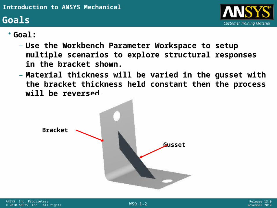
Customer Training Material. . . Preprocessing5. Highlight the part “Bracket”
and enter a thickness = 2mm in the details.
6. Highlight the part “Gusset” and enter a thickness = 1mm in the details.
7. Make both thicknesses parametric by toggling the check box.
8. Highlight the Geometry branch and, in the Property details, toggle the Mass parameter on.
5.
6.
7.
8.

Introduction to ANSYS Mechanical
WS9.1-7ANSYS, Inc. Proprietary© 2010 ANSYS, Inc. All rights reserved.
Release 13.0 November 2010
Customer Training Material. . . Preprocessing9. Highlight the Connections branch, RMB >
Insert > Connections Group.
10. In the details for the connections group change the Auto Detections for Face/Edge to “Yes”.
11. Highlight the connections group “RMB > Create Automatic Connections”.
9.
11.
10.
Introduction to ANSYS Mechanical
WS9.1-8ANSYS, Inc. Proprietary© 2010 ANSYS, Inc. All rights reserved.
Release 13.0 November 2010
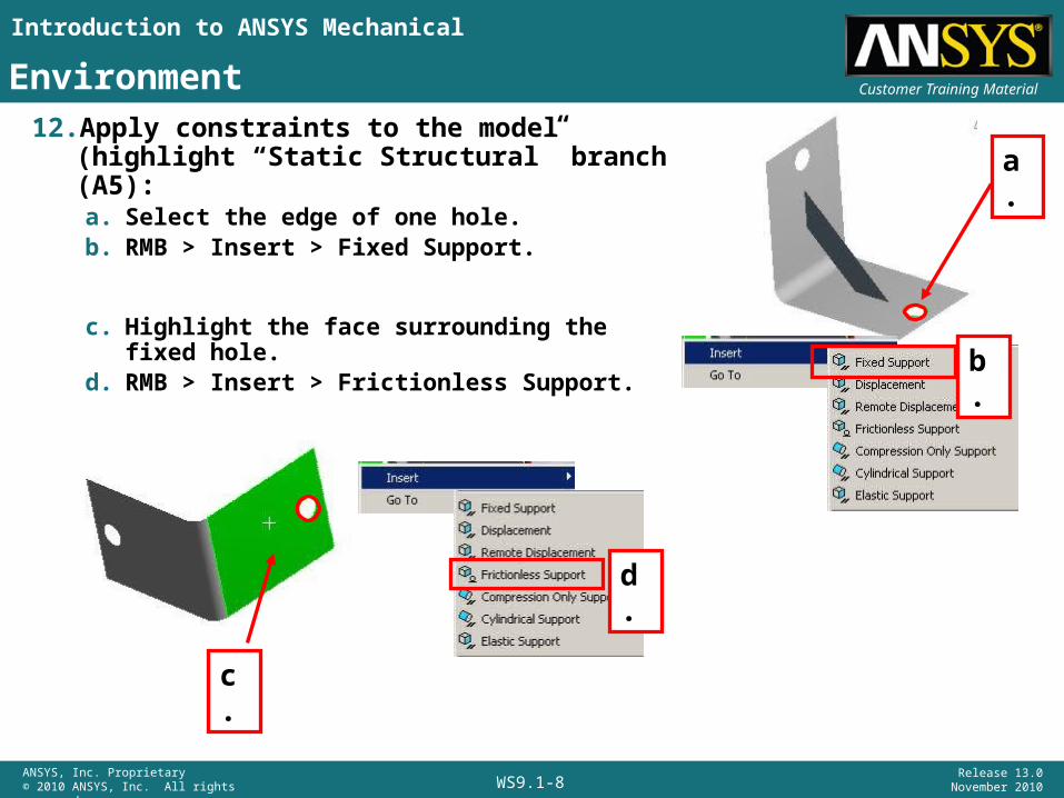
Customer Training MaterialEnvironment12. Apply constraints to the model (highlight
“Static Structural” branch (A5):a. Select the edge of one hole.b. RMB > Insert > Fixed Support.
c. Highlight the face surrounding the fixed hole.d. RMB > Insert > Frictionless Support.
a.
b.
c.
d.
Introduction to ANSYS Mechanical
WS9.1-9ANSYS, Inc. Proprietary© 2010 ANSYS, Inc. All rights reserved.
Release 13.0 November 2010
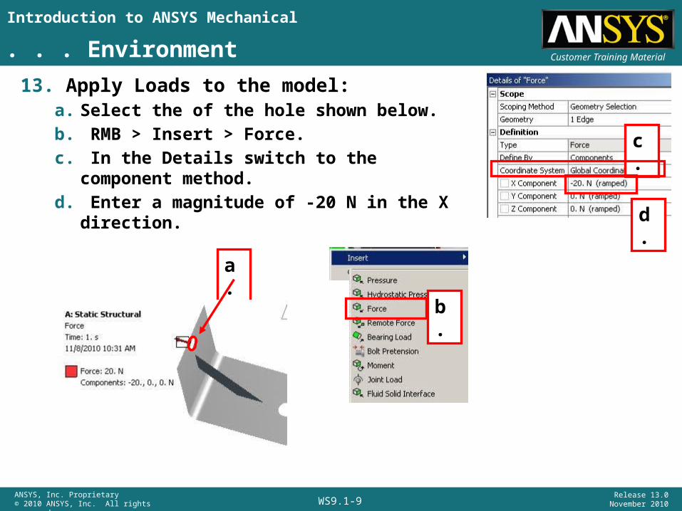
Customer Training Material. . . Environment13. Apply Loads to the model:
a. Select the of the hole shown below.b. RMB > Insert > Force.c. In the Details switch to the component method.d. Enter a magnitude of -20 N in the X direction.
a.
c.
b.
d.
Introduction to ANSYS Mechanical
WS9.1-10ANSYS, Inc. Proprietary© 2010 ANSYS, Inc. All rights reserved.
Release 13.0 November 2010
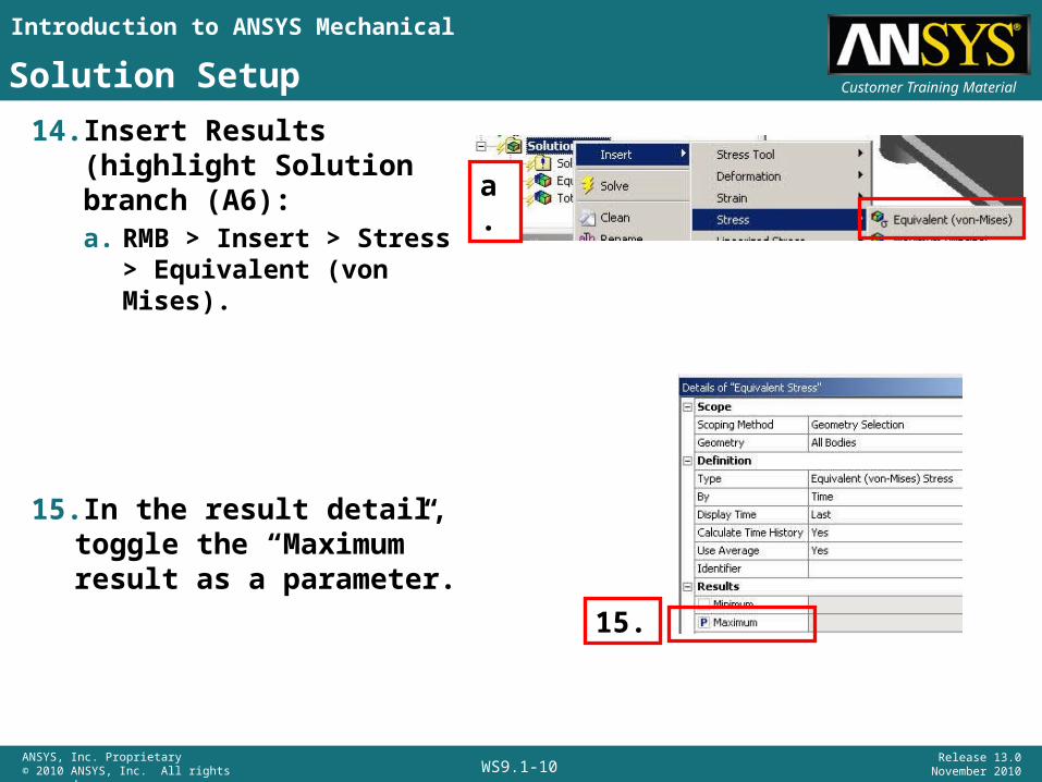
Customer Training MaterialSolution Setup14. Insert Results (highlight
Solution branch (A6):a. RMB > Insert > Stress >
Equivalent (von Mises).
15.In the result detail, toggle the “Maximum” result as a parameter.
a.
15.
Introduction to ANSYS Mechanical
WS9.1-11ANSYS, Inc. Proprietary© 2010 ANSYS, Inc. All rights reserved.
Release 13.0 November 2010
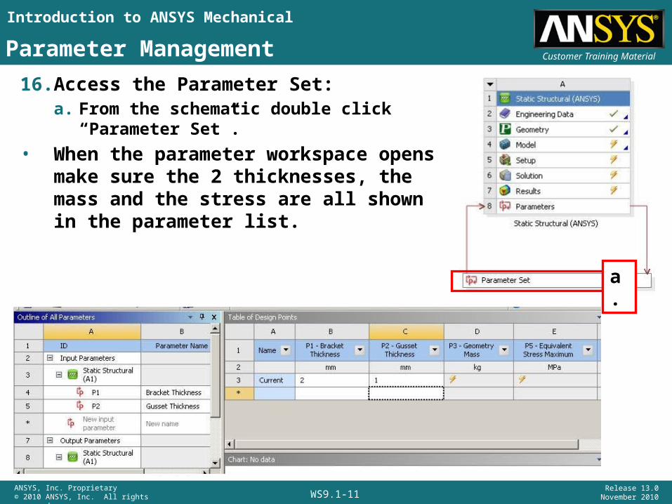
Customer Training MaterialParameter Management16. Access the Parameter Set:
a. From the schematic double click “Parameter Set”.
• When the parameter workspace opens make sure the 2 thicknesses, the mass and the stress are all shown in the parameter list.
a.
Introduction to ANSYS Mechanical
WS9.1-12ANSYS, Inc. Proprietary© 2010 ANSYS, Inc. All rights reserved.
Release 13.0 November 2010
Customer Training Material
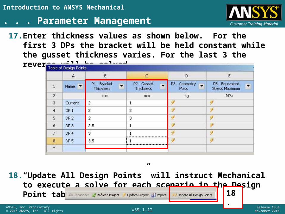
17. Enter thickness values as shown below. For the first 3 DPs the bracket will be held constant while the gusset thickness varies. For the last 3 the reverse will be solved.
18. “Update All Design Points” will instruct Mechanical to execute a solve for each scenario in the Design Point table.
. . . Parameter Management
18.
Introduction to ANSYS Mechanical
WS9.1-13ANSYS, Inc. Proprietary© 2010 ANSYS, Inc. All rights reserved.
Release 13.0 November 2010
Customer Training Material
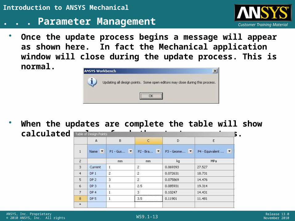
• Once the update process begins a message will appear as shown here. In fact the Mechanical application window will close during the update process. This is normal.
• When the updates are complete the table will show calculated values for both output parameters.
. . . Parameter Management
Introduction to ANSYS Mechanical
WS9.1-14ANSYS, Inc. Proprietary© 2010 ANSYS, Inc. All rights reserved.
Release 13.0 November 2010
Customer Training Material
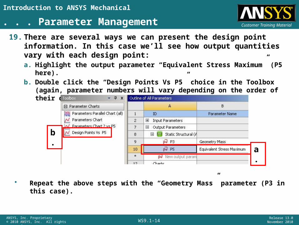
19. There are several ways we can present the design point information. In this case we’ll see how output quantities vary with each design point:a. Highlight the output parameter “Equivalent Stress Maximum” (P5 here).b. Double click the “Design Points Vs P5” choice in the Toolbox (again, parameter
numbers will vary depending on the order of their definition).
. . . Parameter Management
b.
a.
• Repeat the above steps with the “Geometry Mass” parameter (P3 in this case).
Introduction to ANSYS Mechanical
WS9.1-15ANSYS, Inc. Proprietary© 2010 ANSYS, Inc. All rights reserved.
Release 13.0 November 2010
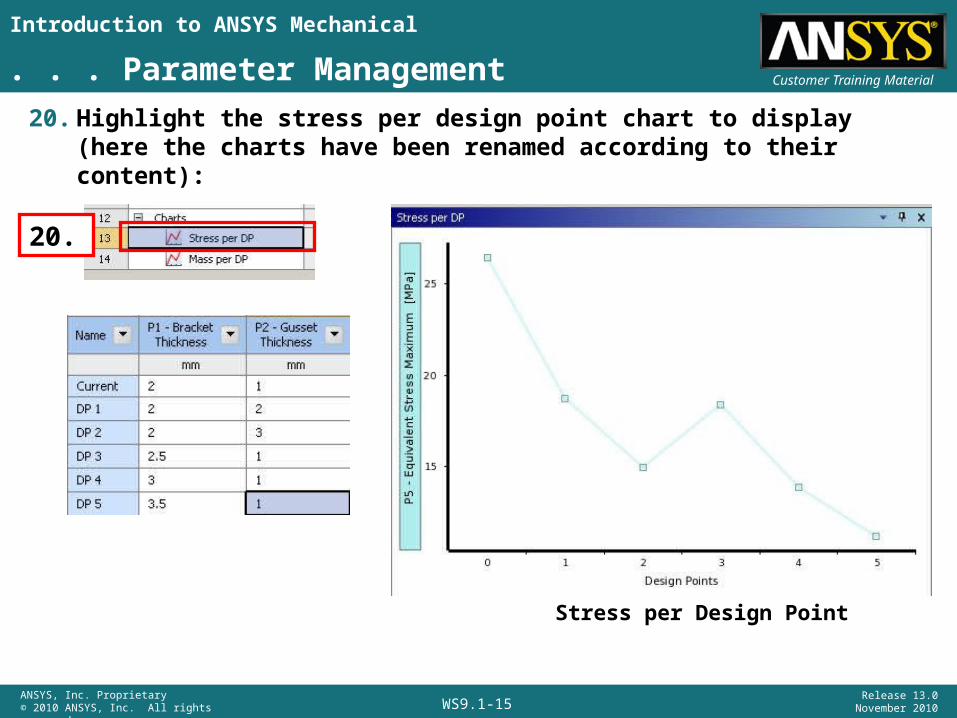
Customer Training Material. . . Parameter Management20. Highlight the stress per design point chart to display (here the charts
have been renamed according to their content):
20.
Stress per Design Point
Introduction to ANSYS Mechanical
WS9.1-16ANSYS, Inc. Proprietary© 2010 ANSYS, Inc. All rights reserved.
Release 13.0 November 2010
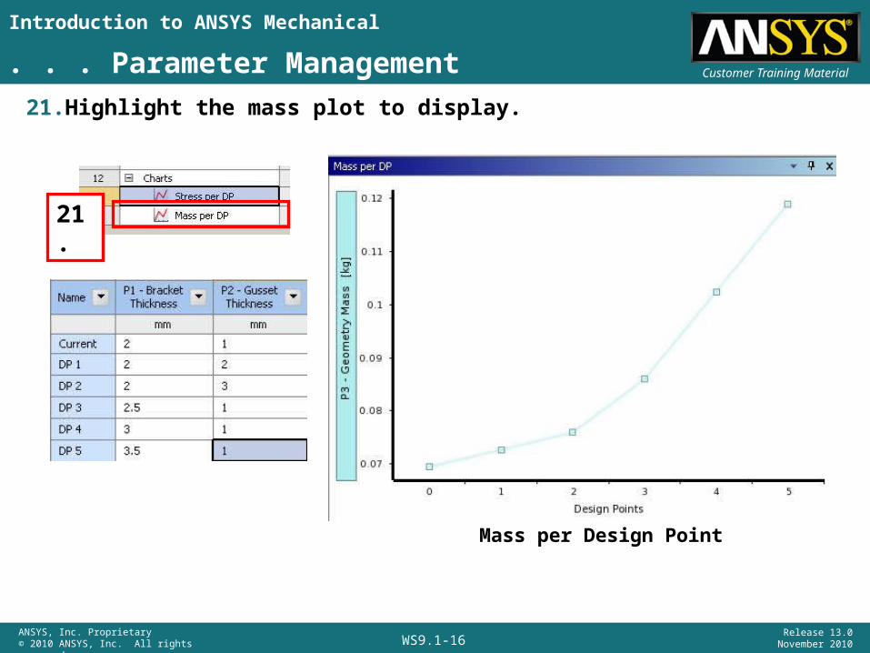
Customer Training Material. . . Parameter Management21. Highlight the mass plot to display.
Mass per Design Point
21.

Introduction to ANSYS Mechanical
WS9.1-17ANSYS, Inc. Proprietary© 2010 ANSYS, Inc. All rights reserved.
Release 13.0 November 2010
Customer Training Material. . . Parameter Management• Repeat step 19 and create a stress vs DP plot.• In the properties window choose to display “Geometry Mass” on the
right side Y axis as shown below.
Plots like this one allow us to visualize the trade off that often accompanies these kinds of choices.