Embed Size (px)
Citation preview

©2014SeeedTechnologyInc. MB_2014_D02
1
MeshBee®
Open Source ZigBee RF Module CookBook
©2014SeeedTechnologyInc.www.seeedstudio.com

©2014SeeedTechnologyInc. MB_2014_D02
2
Doc Version Date Author Remark v0.1 2014/05/07 Oliver Createdv0.2 2014/06/18 Oliver v0.3 2016/1/21 Jack Modifiedtheexampleaccordingtothe
firmwarev1004

©2014SeeedTechnologyInc. MB_2014_D02
3
Table of contents
TableofcontentsChapter 1: Getting Started .............................................................................................. 4
1.1 Introduction ...................................................................................................... 4 1.2 Installing IDE .................................................................................................... 5 1.3 Setting up the MeshBee .................................................................................... 8 1.4 Upgrade firmware ........................................................................................... 10 1.5 Setting up the network .................................................................................... 11
Chapter 2: Example of Mode Operation ....................................................................... 13 2.1 AT mode .......................................................................................................... 13
Additional Documentation ............................................................................ 14 2.2 API Mode ........................................................................................................ 15
Remote led blink example ............................................................................ 15 Sending Data packets example ..................................................................... 18
2.3 MCU Mode ..................................................................................................... 21 Mechanism .................................................................................................... 21 Additional documentation ............................................................................. 23 Blink example in AUPS ................................................................................ 23
2.4 Data Mode ....................................................................................................... 24 Chat example ................................................................................................ 24
Chapter 3: Handle a sleep node .................................................................................... 26 3.1 Typical application scenario ............................................................................ 26 3.2 implementation ............................................................................................... 26 3.3 Configuring Sleep ........................................................................................... 28
Sleep example in AUPS ................................................................................ 28 Chapter 4: Make an RPC .............................................................................................. 32
4.1 What's a micro-RPC? ...................................................................................... 32 4.2 What kind of system can make an RPC? ........................................................ 32 4.3 Why micro-RPC? ............................................................................................ 32 4.2 How to deploy your own PRC method? ......................................................... 32

©2014SeeedTechnologyInc. MB_2014_D02
4
Introduction
Chapter1:GettingStarted1.1 Introduction
MeshBee® is a 2.4 GHz wireless zigbee RF module. It use microchip JN516x from NXP that enables several different flvors of standards-based zigbee mesh networking. Our released firmware
fully supports Zigbee Pro stack. You can use MeshBee® in three different ways: Master Mode: the factory firmware warps the complicated Zigbee stack operation into a few
easy to use serial commands(AT commands). Slave Mode: for a complex mesh network, a host application can send API frames to the
MeshBee® that contain short address and payload information instead of using AT command. Transparent Mode: MeshBee® can also work as a transparent serial communication node that
can be part of a simple point-to-point connection. When operating in this mode, the modules act as a serial line replacement - all UART data received through UART1 is directly send to a specified remote node.

©2014SeeedTechnologyInc. MB_2014_D02
5
Installing IDE
1.2 InstallingIDE
NXP provides full-scale development environment, tools and documents. The development environment consists of the SDK toolchain and the ZigBee stack SDK. Please visit NXP's website to get some detailed description: http://www.nxp.com/techzones/wireless-connectivity/smart-energy.html
To create the development environment, perform these steps: 1) Install JN-SW-4041 SDK Toolchain to default disk: C:/ 2) Install JN-SW-4064 ZigBee Smart Energy SDK to default disk: C:/ 3) Install JN-SW-4067-JN516x ZigBee Home Automation SDK to default disk C:/
Note: MeshBee’s factory firmware is developed on top of the smart energy profile.

©2014SeeedTechnologyInc. MB_2014_D02
6
Installing IDE
When finished the installing, you can test the tool chain if you are not sure whether it is successful or not. Perform these steps:
1) Clone the latest firmware source code from github. 2) Copy the source code folder to C:/Jennic/Application/. 3) Open Jennic Bash Shell. 4) Type these shell commands:
cd MeshBeeMasterBranch cd build ./build.sh
Note: The developing toolchain supports windows only. For Linux and Mac users, a windows VM is recommended.
Note: execute ./build.sh or ./build_xxx_clean.sh + ./build_xxx.sh. Make sure the “clean” step was taken.

©2014SeeedTechnologyInc. MB_2014_D02
7
Installing IDE
If three binary files are generated successfully, congratulations, you have finished all the
preparation work.
Open eclipse IDE and import the project, you can catch a glimpse of the firmware:
To edit the .oscfgdiag file and .zpscfg file, you should install the eclipse plugins according to the guide in
section 6.2.2 in <SDK Installation and User Guide.pdf>.

©2014SeeedTechnologyInc. MB_2014_D02
8
Setting up the MeshBee
1.3 SettinguptheMeshBee
To assemble your experimental environment, perform the following steps: 1) Step1: Insert MeshBee into the socket of UartBeeV5; 2) Step2: Connecting UartBeeV5 with PC by USB port;

©2014SeeedTechnologyInc. MB_2014_D02
9
Setting up the MeshBee
Note: Switch the SW to “3V3” and SW3 to “Prog” position at first.

©2014SeeedTechnologyInc. MB_2014_D02
10
Upgrade firmware
1.4 Upgradefirmware
A wireless network comprises a set of nodes that can communicate with each other by means of radio transmissions according to a set of routing rules (for passing messages between nodes). ZigBee network includes three types of node:
1) Coordinator: This is the first node to be started and is responsible for forming the network by
allowing other node to join the network through it. 2) Router: This is the node with routing capability, and is also able to send/receive data. 3) End device: Only capability to send/receive data.
Different device role should burn different image. Burn the latest firmware using JN51xx Flash Programmer. Four steps are required as below:

©2014SeeedTechnologyInc. MB_2014_D02
11
Setting up the network
1.5 Settingupthenetwork
Zigbee network lifecycle
Note: When you burn a new binary file which is different from the previous one. For example: burn an end.bin overwrite the coo.bin, you should erase the EEPROM completely at frist.

©2014SeeedTechnologyInc. MB_2014_D02
12
Setting up the network
Normally, MeshBee will form the Network automatically. If a router or end device failed to join network, you can use command “ATRS” to rescan and perform network actions again.

©2014SeeedTechnologyInc. MB_2014_D02
13
Example of Mode operation
Chapter2:ExampleofModeOperation
MeshBee has four different types of mode: AT, API, DATA, MCU, illustrated in figure below:
No matter which mode MeshBee works in, input “+++” can go back to AT command mode.
2.1 ATmode
The AT commands that MeshBee radios use for interactive are a descendant of hayes command set. Every AT command starts with “AT”, and followed by two characters that indicate which command is being executed, then by some optional configuration values.
To communicate with MeshBee from Win7, we will use SecureCRT. In CoolTerm on a Mac, the procedure works pretty much the same.

©2014SeeedTechnologyInc. MB_2014_D02
14
Example of Mode operation
Use AT commands is very easy. Here are the steps: 1) Input “+++” to go to AT command mode. 2) Wait for a MeshBee “ok” response. 3) To read a register, just typing an AT command. 4) To set a register, type an AT command followed by the register value.
AT command contain three different types:
Additional Documentation
For more information about the AT command operations, please refer to the MeshBee User’s manual v0.1.
Note: The baud-rate must be set to 115200 in SecureCRT. Make sure MeshBee works in AT mode.

©2014SeeedTechnologyInc. MB_2014_D02
15
Example of Mode operation
2.2 APIMode
API is simply a set of standard interfaces created to allow other MCU to interact with MeshBee. For our purposes, API supports local operation and remote operation. For example, a host application can send an “ATIO” frame to Coordinator A, A will set its GPIO when it receives this frame. The most important thing to note is that APIs are specifically engineered to enable MeshBee to talk efficiently to other MCU. The target of API-mode is to transmit highly structured data quickly and reliably.
Remote led blink example
Sending commands over the wireless network to control the remote device is kind of exhilarating, it is something you can accomplish in API mode.
Some kinds of AT commands can also be sent wirelessly for execution on remote device. Here, we implement a remote IO control demo.
Hardware list:
Arduino X1 MeshBee X2 XBee shield X1 UartBeeV5 X1

©2014SeeedTechnologyInc. MB_2014_D02
16
Example of Mode operation
Install hardware like that:
1) Connect Arduino with MeshBee’s Coordinator through UART, switch ‘USB_UART_M8’ to M8 side, switch ‘D11/D12_XBEE_UART’ to UART side.
2) Connect MeshBee’s Router with UartBeeV5.
This example will send API packet from Coordinator, and control the RSSI led on the UARTSBee where the Router is plugged in. You should setup the network first to make the Router connect to the Coordinator, then put the Coordinator into API mode with the ATAP command. (The Rounter can be under any mode, it will always accept the remote command.)
Arduino sketch: #include <Arduino.h> /* LED Pin */ int led = 13; /* declaration */ void remoteATIO_Onoff(unsigned char onoff); void setup() { pinMode(led, OUTPUT); /* open the serial port at 115200 bps */ Serial.begin(115200); } void loop() {

©2014SeeedTechnologyInc. MB_2014_D02
17
Example of Mode operation
remoteATIO_Onoff(1); digitalWrite(led, LOW); delay(500); remoteATIO_Onoff(0); digitalWrite(led, HIGH); delay(500); } /* Turn on/off remote Led */ void remoteATIO_Onoff(unsigned char onoff) { unsigned char remote_at_req[] = { 0x01, //frame ID 0x00, //option 0x70, //AT cmd index //-- start of 4 bytes 0x00, //read/write: 0x00 - write 0x09, //IO pin - RSSI 0x00, //State 0x00, //-- end of 4 bytes 0xf5, //unicast addr high byte 0x28, //unicast addr low byte 0x00,0x00,0x00,0x00,0x00,0x00,0x00,0x00 //unicast long addr }; remote_at_req[5] = onoff; int frm_len = sizeof(remote_at_req); unsigned char sum = 0; for (int i=0; i<frm_len; i++) { sum += remote_at_req[i]; } Serial.write(0x7e); //start delimiter Serial.write(frm_len); //length Serial.write(0x17); //API identifier: remote AT require Serial.write(remote_at_req, frm_len); //API_REMOTE_AT_REQ frame Serial.write(sum); //check sum }
Sending Data packets example Now that you may understand how API mode works. It’s simple enough to
write your own MCU code to work with API mode. Sometimes, you want to send some data packet in your protocol. API data
packet can meet your requirements. This example uses the same hardware as the remote led blink example.
Steps should be done: 1) Configure the Router into data mode with the ATDT command. 2) Reflash the Arduino board with the following code.

©2014SeeedTechnologyInc. MB_2014_D02
18
Example of Mode operation
Arduino sketch: #include <Arduino.h> /* LED Pin */ int led = 13; /* declaration */ void sendDataPkt(); void setup() { pinMode(led, OUTPUT); /* open the serial port at 115200 bps */ Serial.begin(115200); } void loop() { digitalWrite(led, LOW); delay(500); digitalWrite(led, HIGH); delay(500); sendDataPkt(); } void sendDataPkt() { unsigned char data_pkt[] = { 0x01, //frame ID 0x00, //option 0xf5, //unicast addr high byte 0x28, //unicast addr low byte 0x00,0x00,0x00,0x00,0x00,0x00,0x00,0x00, //unicast long addr 0x07, //data length 's', //data begin 'e', 'e', 'e', 'd', '\r', '\n' }; int frm_len = sizeof(data_pkt); unsigned char sum = 0; for (int i=0; i<frm_len; i++) { sum += data_pkt[i]; } Serial.write(0x7e); //start delimiter Serial.write(frm_len); //length Serial.write(0x02); //API identifier: API_DATA_PACKET Serial.write(data_pkt, frm_len); //API_DATA_PACKET frame Serial.write(sum); //check sum }
Notice that the length of the data block can be flexible but with the right
data length specified.
©2014SeeedTechnologyInc. MB_2014_D02
19
Example of Mode operation
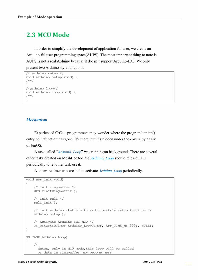
2.3 MCUMode
In order to simplify the development of application for user, we create an Arduino-ful user programming space(AUPS). The most important thing to note is AUPS is not a real Arduino because it doesn’t support Arduino-IDE. We only present two Arduino style functions: /* arduino setup */ void arduino_setup(void) { /**/ } /*arduino loop*/ void arduino_loop(void) { /**/ }
Mechanism
Experienced C/C++ programmers may wonder where the program’s main() entry point function has gone. It’s there, but it’s hidden under the covers by a task of JenOS.
A task called “Arduino_Loop” was running on background. There are several other tasks created on MeshBee too. So Arduino_Loop should release CPU periodically to let other task use it.
A software timer was created to activate Arduino_Loop periodically. void ups_init(void) { /* Init ringbuffer */ UPS_vInitRingbuffer(); /* init suli */ suli_init(); /* init arduino sketch with arduino-style setup function */ arduino_setup(); /* Activate Arduino-ful MCU */ OS_eStartSWTimer(Arduino_LoopTimer, APP_TIME_MS(500), NULL); } OS_TASK(Arduino_Loop) { /* Mutex, only in MCU mode,this loop will be called or data in ringbuffer may become mess

©2014SeeedTechnologyInc. MB_2014_D02
20
Example of Mode operation
*/ if(E_MODE_MCU == g_sDevice.eMode) { /* Back-Ground to search AT delimiter */ uint8 tmp[AUPS_UART_RB_LEN]; uint32 avlb_cnt = suli_uart_readable(NULL, NULL); uint32 min_cnt = MIN(AUPS_UART_RB_LEN, avlb_cnt); /* Read,not pop,make sure we don't pollute user data in AUPS ringbuffer */ vHAL_UartRead(tmp, min_cnt); if (searchAtStarter(tmp, min_cnt)) { /* Set AT mode */ setNodeState(E_MODE_AT); suli_uart_printf(NULL, NULL, "Enter AT Mode.\r\n"); /* Clear ringbuffer of AUPS */ OS_eEnterCriticalSection(mutexRxRb); clear_ringbuffer(&rb_uart_aups); OS_eExitCriticalSection(mutexRxRb); } else { arduino_loop(); } /* * If a sleep event has already been scheduled in arduino_loop, * don't set a new arduino_loop */ if(true == bGetSleepStatus()) return; /* re-activate Arduino_Loop */ if(g_sDevice.config.upsXtalPeriod > 0) { OS_eStartSWTimer(Arduino_LoopTimer, APP_TIME_MS(g_sDevice.config.upsXtalPeriod), NULL); } else { OS_eActivateTask(Arduino_Loop); //this task is the lowest priority } } }
Write your own code in “ups_arduino_sketch.c”, then compile and upload
the binary file to MeshBee. In AT mode, using “ATMFxx” to set the delay period between each
Arduino_Loop. The delay period, which is also called “simulate crystal oscillator frequency” (not a real one), range from 4ms to 3000ms.
Then using “ATMC” to enter MCU mode.
Additional documentation:
©2014SeeedTechnologyInc. MB_2014_D02
21
Example of Mode operation
For more information about the function list that AUPS can call, please
refer to the MeshBee User’s manual v0.1.
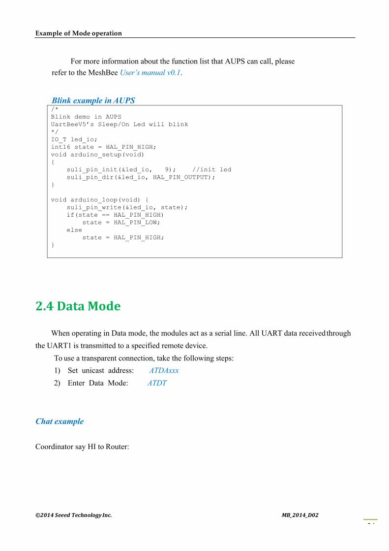
Blink example in AUPS /* Blink demo in AUPS UartBeeV5’s Sleep/On Led will blink */ IO_T led_io; int16 state = HAL_PIN_HIGH; void arduino_setup(void) { suli_pin_init(&led_io, 9); //init led suli_pin_dir(&led_io, HAL_PIN_OUTPUT); } void arduino_loop(void) { suli_pin_write(&led_io, state); if(state == HAL_PIN_HIGH) state = HAL_PIN_LOW; else state = HAL_PIN_HIGH; }
2.4 DataMode
When operating in Data mode, the modules act as a serial line. All UART data received through the UART1 is transmitted to a specified remote device.
To use a transparent connection, take the following steps: 1) Set unicast address: ATDAxxx 2) Enter Data Mode: ATDT
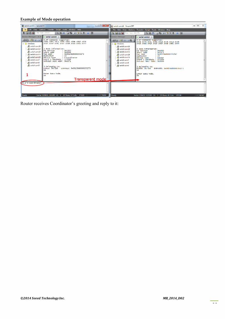
Chat example
Coordinator say HI to Router:
©2014SeeedTechnologyInc. MB_2014_D02
22
Example of Mode operation
Router receives Coordinator’s greeting and reply to it:

©2014SeeedTechnologyInc. MB_2014_D02
23
Example of Mode operation
Coordinator receives Router’s reply:

©2014SeeedTechnologyInc. MB_2014_D02
24
Handle a sleep node
Chapter3:Handleasleepnode
An end device can join networks and participate in communications, but never act as a step stone for any other devices. End device always require a router or the coordinator to be their parent device. In the zigbee stack, only an end device can sleep. When an end device goes to sleep, any external contact will fail because it turns off its trans/receiver and most of the integrated peripherals. Its parent will store a single message for it, and this piece of message will be discarded after 7 seconds, so make sure the traffic is light-weight in a sleep enabled network.
3.1 Typicalapplicationscenario
Using sleep mode, the life of an end device powered by battery can stretch into months and sometimes even years.
1) If the end devices are only needed to send a heartbeat back to the central node cyclically, you can enable the cyclic sleep mode.
2) If the end devices not only require cyclical wake, but also require a button wake, you can enable the cyclic sleep with pin wake mode.
3.2 Implementation
Sleep mode always works with APUS. Two software timer are created to activate bound task, The main implementation was illustrated in figure below:

©2014SeeedTechnologyInc. MB_2014_D02
25
Handle a sleep node
Figure: Implementation of sleep end device

©2014SeeedTechnologyInc. MB_2014_D02
26
Handle a sleep node
3.3 ConfiguringSleep
There are three AT commands associated with sleep mode.
An end device has four sleep behaviors, which can be set with ATSM commands. 1) ATSM0: Disable sleep mode
The end device will never go to sleep in that mode even if you schedule a sleep in AUPS. 2) ATSM1,2,3: These modes are currently undefined, and retained for future use. 3) ATSM4: cyclic sleep mode
The node will sleep and wake cyclically. Set the sleep time using ATSP, set how long before a node goes to sleep using ATST.
4) ATSM5: cyclic sleep mode with pin wake This is generally the same as cyclic sleep mode but also waking by PIO (any of the digital
IO).
Sleep example in AUPS
/*
Sleep demo in AUPS
End device sends ten heartbeats and then sleep 3s
*/
ANALOG_T temp_pin;
void arduino_setup(void)
{
suli_analog_init(&temp_pin, TEMP);
}
Note: Please refer to User’s manual for more details.

©2014SeeedTechnologyInc. MB_2014_D02
27
Handle a sleep node
void arduino_loop()
{
/* Finish user job */
static jobCnt = 0;
uint8 tmp[sizeof(tsApiSpec)]={0};
tsApiSpec apiSpec;
int16 temper = suli_analog_read(temp_pin);
sprintf(tmp, "E-HeartBeat:%ld\r\n", temper);
PCK_vApiSpecDataFrame(&apiSpec, 0xec, 0x00, 0x0000, tmp, strlen(tmp));
/* Air to Coordinator */
uint16 size = i32CopyApiSpec(&apiSpec, tmp);
if(API_bSendToAirPort(UNICAST, 0x0000, tmp, size))
{
suli_uart_printf(NULL, NULL, "<HeartBeat%d>\r\n", jobCnt);
jobCnt++;
}
if(10 == jobCnt)
{
jobCnt = 0;
Sleep(3000);
}
}

©2014SeeedTechnologyInc. MB_2014_D02
28
Make an RPC
Chapter4:MakeanRPC
A micro-RPC framework was implemented in MeshBee firmware. Here is the brief guide for your application programming.
4.1 What'samicro-RPC?
A method used for connecting two remotely placed functions by first using a protocol for connecting the processes. It’s used in the cases of distributed tasks.
Micro-RPC is a tiny RPC framework on resource-limit embedded device.
4.2 WhatkindofsystemcanmakeanRPC?
Each system in peer-to-peer mode can make an RPC. RPC Commands are in the format:
"/<Object name>/<Method name> <Arguments separated by spaces>" This is an example of the RPC command required to turn on a LED on MeshBee:
"/myled/write HIGH"
4.3 Whymicro-RPC?
Divide different kinds of remote procedure into groups which is marked by a simple obj_name.
Time-complexity of the function search is highly reduced with the hash algorithm.
4.2HowtodeployyourownPRCmethod?
1) Open /include/rpc_usr.h at first. 2) Add a set of methods which is divided into groups according to their objName to a
methodEntity. 3) Add one obj(something like air_conditioner, or light_switch) to rpcEntity[]

©2014SeeedTechnologyInc. MB_2014_D02
29
Make an RPC
4) Implement these RPC method.
/*
Rpc demo in rpc_usr.h
modify to meet your request
*/
tsMethodEntity methodEntityA[] = {
{0, "run", A_run},
{0, "stop", A_stop}
};
tsMethodEntity methodEntityB[] = {
{0, "run", B_run},
{0, "stop", B_stop}
};
/* Step2, Rpc Entity: HashKey, objName, MethodArray, MethodNum */
tsRpcEntity rpcEntity[] = {
{0, "home_obj1", methodEntityA, METHOD_ENTITY_SIZE(methodEntityA)},
{0, "office_obj2", methodEntityB, METHOD_ENTITY_SIZE(methodEntityB)},
};
/* Step3, [Rpc Method defined here] */
bool A_run(tsArguments tsArg)
{
DBG_vPrintf(TRACE_RPC, "home_obj is running \r\n");
return TRUE;
}
bool A_stop(tsArguments tsArg)
{
DBG_vPrintf(TRACE_RPC, "home_obj is stopping \r\n");
return TRUE;
}

©2014SeeedTechnologyInc. MB_2014_D02
30
Make an RPC
bool B_run(tsArguments tsArg)
{
DBG_vPrintf(TRACE_RPC, "office_obj2 is running \r\n");
return TRUE;
}
bool B_stop(tsArguments tsArg)
{
DBG_vPrintf(TRACE_RPC, "office_obj2 is stopping \r\n");
return TRUE;
}
After that, you can call these remote functions at any nodes by RPC_vCaller(uint64 macAddress, char* rpcCmd):
eg: RPC_vCaller(0x00158d0000355273, "/home_obj1/run param1 param2");


![RF Module Design - [Chapter 5] Low Noise Amplifier](https://img.pdfslide.tips/doc/110x75/55c6d4bcbb61ebf2428b46cc/rf-module-design-chapter-5-low-noise-amplifier.jpg)

![RF Module Design - [Chapter 1] From Basics to RF Transceivers](https://img.pdfslide.tips/doc/110x75/55cf0481bb61eb002d8b458b/rf-module-design-chapter-1-from-basics-to-rf-transceivers.jpg)
![RF Module Design - [Chapter 8] Phase-Locked Loops](https://img.pdfslide.tips/doc/110x75/55cebb77bb61eba32f8b45bd/rf-module-design-chapter-8-phase-locked-loops.jpg)

![RF Module Design - [Chapter 7] Voltage-Controlled Oscillator](https://img.pdfslide.tips/doc/110x75/55cebbaebb61eb912f8b45f9/rf-module-design-chapter-7-voltage-controlled-oscillator.jpg)