Embed Size (px)
Citation preview
CHAPTER
Methods forTwo-DimensionalCell Confinement
14Mael Le Berre, Ewa Zlotek-Zlotkiewicz, Daria Bonazzi,
Franziska Lautenschlaeger, and Matthieu PielSystems Cell Biology of Cell Division and Cell Polarity, Institut Curie, CNRS, Paris, France
CHAPTER OUTLINE
Introduction............................................................................................................ 214
14.1 Slide Design for Geometrical Confinement ........................................................216
14.2 Geometrical Confinement Slide Fabrication.......................................................217
14.2.1 Materials ................................................................................... 217
14.2.2 Equipment................................................................................. 218
14.2.3 Fabrication ............................................................................... 218
14.2.3.1 Slide Treatment ................................................................. 219
14.3 Soft Confinement Slide Fabrication ..................................................................220
14.3.1 Materials ................................................................................... 220
14.3.2 Equipment................................................................................. 220
14.3.3 Method...................................................................................... 221
14.4 Dynamic Cell Confiner .....................................................................................222
14.4.1 Materials ................................................................................... 223
14.4.2 Design and Fabrication ............................................................... 225
14.4.3 Handling ................................................................................... 225
14.5 Multiwell Confiner ..........................................................................................226
14.5.1 Materials ................................................................................... 226
14.5.2 Fabrication ................................................................................ 227
14.5.3 Handling ................................................................................... 228
14.6 Discussion......................................................................................................228
General Conclusion ................................................................................................. 229
References ............................................................................................................. 229
AbstractProtocols described in this chapter relate to a method to dynamically confine cells in
two dimensions with various microenvironments. It can be used to impose on cells a
Methods in Cell Biology, Volume 121 ISSN 0091-679X
Copyright © 2014 Elsevier Inc. All rights reserved. http://dx.doi.org/10.1016/B978-0-12-800281-0.00014-2213
given height, with an accuracy of less than 100 nm on large surfaces (cm2). The
method is based on the gentle application of a modified glass coverslip onto a
standard cell culture. Depending on the preparation, this confinement slide can
impose on the cells a given geometry but also an environment of controlled stiffness,
controlled adhesion, or a more complex environment. An advantage is that the
method is compatible with most optical microscopy technologies and molecular
biology protocols allowing advanced analysis of confined cells. In this chapter,
we first explain the principle and issues of using these slides to confine cells in a
controlled geometry and describe their fabrication. Finally, we discuss how the na-
ture of the confinement slide can vary and provide an alternative method to confine
cells with gels of controlled rigidity.
INTRODUCTION
Numerousmethods have been used to study cells in a confined environment. Themost
common methods have certainly been three-dimensional (3D) cell cultures, which in-
volve embedding cells in a gel or another 3D material (see Justice, Badr, & Felder,
2009). Although these methods offer environmental conditions for cells that are close
to those of intermediate tissues in vivo, the various physical parameters of the cell en-
vironment (geometry adhesion, environment elasticity, etc.) are not homogeneous and
well defined, making it difficult to decipher their respective roles. Moreover, observa-
tion is challenging since cells can migrate in the three dimensions, limiting the possi-
bilities of high-resolution microscopy. To circumvent these limitations, other methods
have been developed. Among them, many have been driven to a large extent by tech-
nological developments that allow controlling forces or geometries at the micrometer
scale, for example, apparatuses such as atomic force microscopes, microplates, or mi-
cromanipulators that have been designed by physicists to manipulate single cells and
constrain them in various manners (see Mitrossilis et al., 2010). The main advantage
of these approaches is the possibility to dynamically measure and control forces on
a single cell. On the other hand, statistical and molecular analysis of a single cell is
challenging. Microfluidic channels offer a different strategy to answer specific ques-
tions using simple ways to confine cells in a given geometry (see Velve-Casquillas
et al., 2010). These channels allow the observation of many cells at the same time
and offer tools to control specifically the microenvironment of the cell (chemical gra-
dients, temperature, electric fields, etc.). Even though thesemicrochannels are suitable
to obtain statistics and build complex environments, the dynamic change of cell
confinement and molecular analyses remain challenging in these conditions.
Here we describe an intermediary method that allows confining a population of
adherent cells in a culture without the need to detach them from their original culture
substrate. Because the confinement is applied on a population of cells, statistical data
are easy to obtain, and because confinement can be released, the cell material is us-
able for further study (immunofluorescence, Western blot, qPCR [quantitative poly-
merase chain reaction], or other molecular analysis). The method is based on the
gentle application of a confining slide on the cultured cell (Fig. 14.1A) using a
214 CHAPTER 14 Methods for 2D Cell Confinement
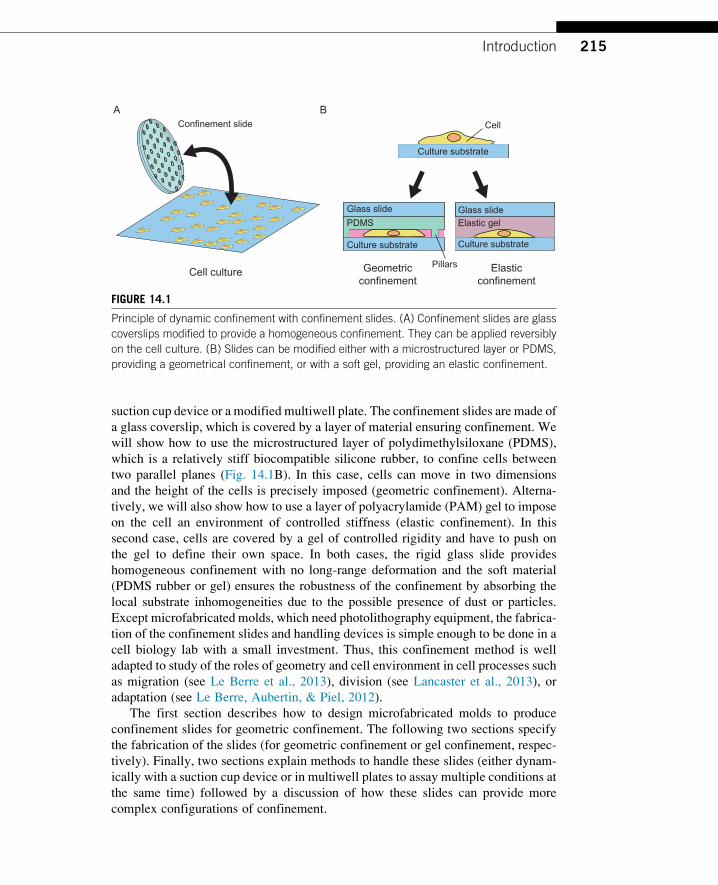
suction cup device or a modified multiwell plate. The confinement slides are made of
a glass coverslip, which is covered by a layer of material ensuring confinement. We
will show how to use the microstructured layer of polydimethylsiloxane (PDMS),
which is a relatively stiff biocompatible silicone rubber, to confine cells between
two parallel planes (Fig. 14.1B). In this case, cells can move in two dimensions
and the height of the cells is precisely imposed (geometric confinement). Alterna-
tively, we will also show how to use a layer of polyacrylamide (PAM) gel to impose
on the cell an environment of controlled stiffness (elastic confinement). In this
second case, cells are covered by a gel of controlled rigidity and have to push on
the gel to define their own space. In both cases, the rigid glass slide provides
homogeneous confinement with no long-range deformation and the soft material
(PDMS rubber or gel) ensures the robustness of the confinement by absorbing the
local substrate inhomogeneities due to the possible presence of dust or particles.
Except microfabricated molds, which need photolithography equipment, the fabrica-
tion of the confinement slides and handling devices is simple enough to be done in a
cell biology lab with a small investment. Thus, this confinement method is well
adapted to study of the roles of geometry and cell environment in cell processes such
as migration (see Le Berre et al., 2013), division (see Lancaster et al., 2013), or
adaptation (see Le Berre, Aubertin, & Piel, 2012).
The first section describes how to design microfabricated molds to produce
confinement slides for geometric confinement. The following two sections specify
the fabrication of the slides (for geometric confinement or gel confinement, respec-
tively). Finally, two sections explain methods to handle these slides (either dynam-
ically with a suction cup device or in multiwell plates to assay multiple conditions at
the same time) followed by a discussion of how these slides can provide more
complex configurations of confinement.
Geometricconfinement
Cell culture
Confinement slide
Elasticconfinement
Glass slide Glass slide
Culture substrate Culture substrate
PDMS
Pillars
Elastic gel
Culture substrate
Cell
A B
FIGURE 14.1
Principle of dynamic confinement with confinement slides. (A) Confinement slides are glass
coverslips modified to provide a homogeneous confinement. They can be applied reversibly
on the cell culture. (B) Slides can be modified either with a microstructured layer or PDMS,
providing a geometrical confinement, or with a soft gel, providing an elastic confinement.
215Introduction

14.1 SLIDE DESIGN FOR GEOMETRICAL CONFINEMENTFor geometrical confinement, microspacers have to be molded under the confine-
ment slides in a PDMS layer in order to control the distance between the slide
and the culture substrate.
To get a robust confinement, the geometry of these spacers needs to be controlled.
If the pillars are too close, many cells will be squashed by the pillars, but if they are
too sparse, the glass slide sags in between the pillars, and the thickness of the cells is
weakly controlled. In addition, if the surface of the pillars is large, a large proportion
of the cells will be squashed, but, if the pillars are too small, they deform under
pressure, giving an uncontrolled confinement height.
An optimal geometry of these spacers has been determined by in silicomechanical
simulations to get pillars as far as possible from each other while making negligible
long-range deformation of the confinement geometry (<100 nmwhen a 10-kPa pres-
sure is applied on the slide) and a small amount of squashed cells (6%) (see Le Berre
et al., 2012). Typically, spacers of 440 mm in diameter spaced by 1 mm in a hexagonal
network providemeet these specifications (see Fig. 14.2A). Note that this geometry is
adapted to confine cells to thicknesses above 3 mm.Below this height, sagging ismore
pronounced, and acapillary effect often sticks thePDMSlayeron the culture substrate,
squashing the cells on the whole surface.
Based on this geometry, we need a mold to imprint the structures on the confine-
ment slides. This mold can be produced by photolithography of a layer of photoresist
deposited on a silicon wafer by using standard microfabrication protocols. These
protocols require a photomask that is used to shade a layer of photoresist from
A B
1 mm
D
440 mm
FIGURE 14.2
Optimal geometry of the pillars for geometrical confinement. (A) Dimensions of the pillars in a
round slide of diameter D. Typically, D¼10 mm for the suction cup device, and D¼18 mm
for a 6-well plate, and D¼12 mm for a 12-well plate. The number of pillars has to be adapted
depending on D. (B) Photomask to produce a negative photoresist layer (such as SU8)
corresponding to the design in (A).
216 CHAPTER 14 Methods for 2D Cell Confinement
the applied UV light and define the shape of the spacer after development of the
photoresist. With this fabrication mode, the thickness of the photoresist layer
corresponds to the height of the pillars and, therefore, the thickness of the cells after
confinement. If manipulated carefully, a mold can be used many times. Thus, it is not
necessary to have access to a microfabrication facility, and the mold, which is tech-
nically easy to fabricate, can be created by a specialized collaborator or a microflui-
dic foundry company. The mold provider usually needs a drawing of the photomask
in DXF (Drawing eXchange Format) or GDSII (Graphic Database System II) format,
which can be done easily with CAD software like AutoCAD (Autodesk) or L-Edit
(Tanner). But due to the poor resolution required to produce the mold, the mask can
also be printed on a plastic sheet with a high-resolution printer by using a simple
drawing software like Adobe Illustrator. This way, many academic microfabrication
facilities can make such a mold for less than $200. (For more details on mold
fabrication, see, for example, Velve-Casquillas et al., 2010.)
14.2 GEOMETRICAL CONFINEMENT SLIDE FABRICATIONThis section describes the fabrication of stiff confinement slides for geometrical
confinement.
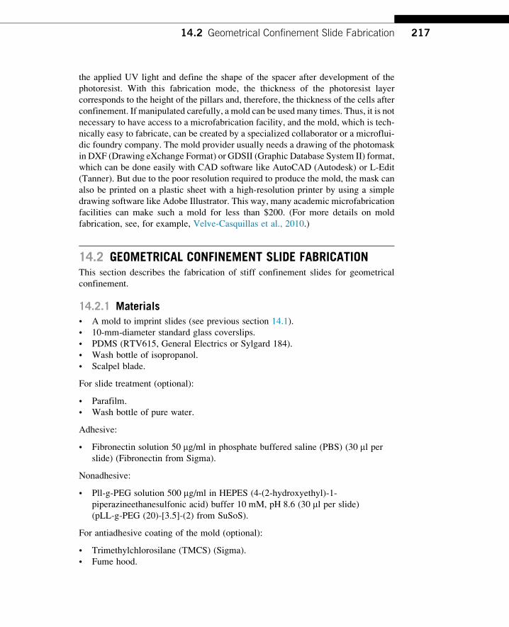
14.2.1 Materials• A mold to imprint slides (see previous section 14.1).
• 10-mm-diameter standard glass coverslips.
• PDMS (RTV615, General Electrics or Sylgard 184).
• Wash bottle of isopropanol.
• Scalpel blade.
For slide treatment (optional):
• Parafilm.
• Wash bottle of pure water.
Adhesive:
• Fibronectin solution 50 mg/ml in phosphate buffered saline (PBS) (30 ml perslide) (Fibronectin from Sigma).
Nonadhesive:
• Pll-g-PEG solution 500 mg/ml in HEPES (4-(2-hydroxyethyl)-1-
piperazineethanesulfonic acid) buffer 10 mM, pH 8.6 (30 ml per slide)(pLL-g-PEG (20)-[3.5]-(2) from SuSoS).
For antiadhesive coating of the mold (optional):
• Trimethylchlorosilane (TMCS) (Sigma).
• Fume hood.
21714.2 Geometrical Confinement Slide Fabrication

14.2.2 Equipment• Plasma cleaner (for example, PDC-32G, Harrick).
• Pressurized, filtered, and oil-less air stream.
• Hot plate.
14.2.3 Fabrication (Fig. 14.3A–F)1. Prepare 10 g of PDMS mix with a ratio of PDMS/cross-linker (A/B) of 8/1
(w/w), avoiding introducing too many bubbles during mixing. PDMS can be
mixed either manually with a simple swizzle stick or with an automatic
planetary mixer (e.g., ARE-250, Thinky). If the PDMS is mixed manually,
bubbles can be removed by centrifugation (2 min at 1000 rpm). Be careful in
A
B
B C
D D2
E F
C
D
E
F
Si
Glc
Pd
Res
Rb
Rb
Ipa
Mo
Pd
Gr
Cs Cs
PrPr
Pr
FIGURE 14.3
Confinement slide fabrication. The schemes and corresponding photos summarize the
fabrication process: (A) Start with a microfabricated mold (Mo) made of a silicon wafer (Si)
covered by a patterned layer of photoresist (Res). (B) A drop of PDMS (Pd) is placed on
the mold, for instance, with the help of a glass rod (Gr). (C) A plasma-activated glass coverslip
(Glc) is pressed onto the drop of PDMS with the help of tweezers in order to keep only a
residual layer of PDMS under the coverslip. The excess PDMS should make rims around the
coverslips (Pr). (D) After baking, the PDMS rims (Pr) are removed. (D2) No residual
PDMS should be visible on the mold at this stage. (E) To unmold the confinement slide (Cs),
the slide is wet in isopropanol (Ipa) before a razor blade (Rb) is introduced between the
mold and the slide. (F) After unmolding, the confinement slide (Cs) is rinsed with isopropanol
and air dried.
218 CHAPTER 14 Methods for 2D Cell Confinement
this case that PDMS is well mixed because unreticulated PDMS is very difficult
to remove and can make your mold unusable.
2. Place the 10-mm glass coverslips on a big glass slide and treat it in the plasma
cleaner for 2 min at maximum power in order to activate one side of the slide
(when the plasma is on, the plasma may produce a dense pink glow). This step
allows the glass slide to stick onto the PDMS layer in the next step.
3. With a glass rod or equivalent, distribute drops of PDMS on the mold in the
places you want to put the plasma-treated coverslips (Fig. 14.3B).
4. Place the coverslips on top of the drop and push gently with tweezers
everywhere on top of the coverslips to keep only a very thin layer of PDMS
under the coverslip. If you push too hard on the coverslip, it will break, and, if
you push too gently, the residual layer of PDMSwill be too thick, and the pillars
will collapse. To gauge the right pressure, notice that it corresponds to the
minimum pressure where you see a small white star appearing under the
tweezers. Do not use sharp tweezers: You will break your coverslips! The
ejected PDMS should form a rim partially covering the slide (Fig. 14.3C).
5. Bake the mold with the coverslips on the hot plate at 95 �C for 15 min. At this
step, if the PDMS is baked too long or not long enough, it will stick too strongly
to the mold, and it will be very difficult to unstick confining slides without
breaking them.
6. Remove the PDMS rim with tweezers (Fig. 14.3D).
7. Place a droplet of isopropanol on the mold; it will help to unmold the slide.
8. Usea razorblade togentlyunstick thecoverslip fromthemold.Toavoid scratching
the mold (molds made of photoresist are very easy to scratch) or breaking the
coverslip, use the followingmethod:At the beginning, place the razor blade on the
edge between themold and the coverslip at an angle of 20�, and then carefully slidethe blade under the confining coverslip parallel to the mold surface (Fig. 14.3E).
9. Rinse the coverslip with isopropanol.
10. Dry the confining coverslip with an air gun (otherwise it will leave stains and
inhomogeneities on the confining slide surface) (Fig. 14.3 F).
11. Gently clean the mold with a clean wipe soaked with isopropanol.
12. Optional: If the mold becomes too sticky and coverslips are difficult to detach,
use an antiadhesive agent. For this step, work under a fume hood: TMCS is very
toxic. Carefully clean the mold with isopropanol and a soft cleaning paper wipe
(e.g., Kimtech, Kimberly-Clark), and put it in a petri dish. Seed two or three
drops of TMCS around the mold, and close the petri dish. The drops will
evaporate and react with the surface. After 5 min, open the petri dish, and vent
the remaining TMCS vapors for 5 min, then bake the mold for 10 min at 70 �Cto stabilize the surface.
14.2.3.1 Slide treatmentThe coverslip can be used either without any treatment (it is not toxic to the cells) or
with a chemical treatment to promote or avoid cell adhesion. However, we advise
treating the confining slide systematically in order to avoid trapping air bubbles
21914.2 Geometrical Confinement Slide Fabrication
between the slide and the substrate, which can kill the cells (PDMS is very hydro-
phobic and often retains air bubbles on its surface).
1. For nonadhesive treatment only: Place the confinement slide on a big glass slide
with the PDMS side facing upward, and treat it in the plasma cleaner for 30 s
maximum at maximum power in order to activate the PDMS surface.
2. On a piece of parafilm, drop 30 ml of the fibronectin solution (for adhesive
treatment) or of the pLL-g-PEG solution (for nonadhesive treatment).
3. Place the confinement slide on the drops, the structured slide in contact with the
solution, and wait for 30 min.
4. Rinse extensively with pure water.
5. Dry the slide with an air jet.
14.3 SOFT CONFINEMENT SLIDE FABRICATIONThis section describes the fabrication of soft confinement slides for elastic
confinement.
14.3.1 Materialsa. Coverslips (any glass coverslip size can be used).
b. Ethanol 70%.
c. Deionized water.
d. Acrylamide 40% (Biorad).
e. Bis-acrylamide 2% (Biorad).
f. 10 mM HEPES buffer pH 7.6.
g. Irgacure 0.5% in 10 mM HEPES pH 7.6 (Irgacure 2959, CIBA). The Irgacure
stock solution has to be protected from light.
h. Aminopropyltrimethoxysilane (APTMS) (Sigma) 4% solution in acetone.
i. Clean and smooth PMMA (polymethyl methacrylate) plate (Good Fellow)
(Also available under the commercial name of “plexiglas”).
j. PDMS (RTV615, GE).
k. Wash bottle of isopropanol.
14.3.2 Equipmentl. Ultrasonic bath.
m. Plasma cleaner (e.g., PDC-32G, Harrick).
n. UV lamp (e.g., Delolux 03 S).
o. Fume hood.
p. Vacuum bell cloche.
220 CHAPTER 14 Methods for 2D Cell Confinement
14.3.3 Method1. Coverslip surface preparation
a. Wash the glass coverslip with ethanol 70% and dry it.
b. Expose the dry coverslips to air plasma for 30 s, maximum power.
c. Incubate clean slides in a solution of APTMS (4% in acetone) for 30 min
under sonication.
d. Wash with distilled water, and air dry (slides can be stored for several weeks
at room temperature).
e. Place the slide on a drop of glutaraldehyde solution (0.5% in PBS) for 30 min.
It is convenient to do it on a laboratory parafilm. Drops of 100 ml are sufficientfor coverslips of 18 mm. Keep track of the side of the coverslip that was
treated. Coverslips should be used right after this step. (Glutaraldehyde is
toxic and an irritant, and it has to be manipulated under a fume hood.)
f. Wash coverslips with distilled water, and air dry.
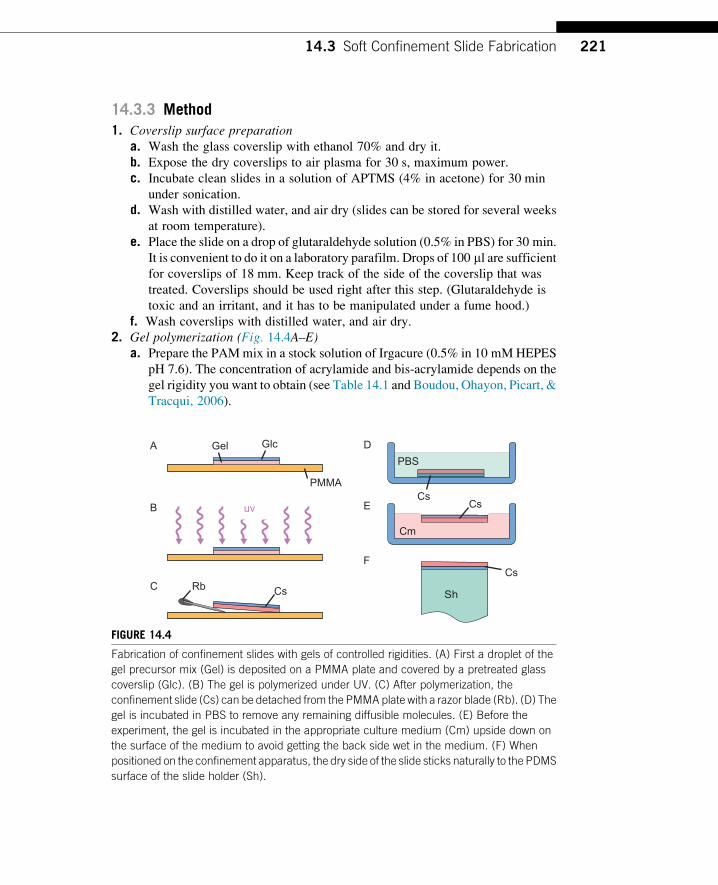
2. Gel polymerization (Fig. 14.4A–E)a. Prepare the PAMmix in a stock solution of Irgacure (0.5% in 10 mMHEPES
pH 7.6). The concentration of acrylamide and bis-acrylamide depends on the
gel rigidity you want to obtain (see Table 14.1 and Boudou, Ohayon, Picart, &
Tracqui, 2006).
A
C
D
Rb Cs
Gel Glc
PMMA
uv
PBS
E
F
Cm
Cs
Cs
CsB
Sh
FIGURE 14.4
Fabrication of confinement slides with gels of controlled rigidities. (A) First a droplet of the
gel precursor mix (Gel) is deposited on a PMMA plate and covered by a pretreated glass
coverslip (Glc). (B) The gel is polymerized under UV. (C) After polymerization, the
confinement slide (Cs) can be detached from the PMMA plate with a razor blade (Rb). (D) The
gel is incubated in PBS to remove any remaining diffusible molecules. (E) Before the
experiment, the gel is incubated in the appropriate culture medium (Cm) upside down on
the surface of the medium to avoid getting the back side wet in the medium. (F) When
positioned on the confinement apparatus, the dry side of the slide sticks naturally to the PDMS
surface of the slide holder (Sh).
22114.3 Soft Confinement Slide Fabrication
b. Put drops of the PAM solution on the PMMA plate, and gently place the
coverslips on them with the treated surface toward the PAM solution (the
coverslip should float on the drop). The volume of the drops can be adapted
according to the thickness of the gel you want to obtain (200 ml for an 18-mm
coverslip will result in gels of �0.8 mm during the fabrication, but note that
the gel will swell to �2 mm after incubation) (Fig. 14.4A).
c. Place the setup under a UV lamp for 10 min (Fig. 14.4B).
d. Carefully detach the coverslips with gel from the plastic using a razor blade or
a scalpel (Fig. 14.4C), and quickly place it in sterile PBS for incubation
overnight (Fig. 14.4D).
e. Before experiments with cells, gels have to be incubated at least 2 h in the
cell culture medium that will be used during the experiment. If drugs will
be used in the experiment, the gel has to be incubated in the medium
containing the appropriate concentration of the given drug. To avoid wetting
the back side of the confinement slide, it can be deposited upside down on
the medium surface. This way, the slide will be incubated floating on the
surface (Fig. 14.4E).
14.4 DYNAMIC CELL CONFINERThe application of the confinement slide on the cultured cells can be done in several
ways. In all cases, a slight pressure (�10 kPa) has to be applied on the slide to get a
robust and uniform contact with the substrate of the cultured cells, and tangential
movement must be eliminated to avoid shearing the cells. A practical way to proceed
is to use the so-called cell confiner that is described in this section.
The cell confiner is a device that acts as a suction cup, as shown in Figure 14.5. It
is composed of a soft empty part that forms a sealed cavity when it is placed on a
surface. When a vacuum is created in the sealed cavity, the device is stuck on the
substrate and cannot move. In the center of the empty part, a piston holds the
confinement slide, which can be displaced vertically by changing the strength of
the vacuum in the device. After the threshold strength of the vacuum is applied,
the confinement slide comes into contact with the cultured cells.
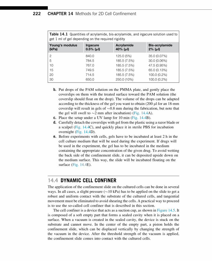
Table 14.1 Quantities of acrylamide, bis-acrylamide, and irgacure solution used to
get 1 ml of gel depending on the required rigidity
Young’s modulus(kPa)
Irgacure0.5% (ml)
Acrylamide40% (ml)
Bis-acrylamide2% (ml)
2 840.0 125.0 (5%) 35.0 (0.07%)
5 784.5 185.5 (7.5%) 30.0 (0.06%)
10 767.0 185.5 (7.5%) 47.5 (0.95%)
15 749.5 185.5 (7.5%) 65.0 (0.13%)
20 714.5 185.5 (7.5%) 100.0 (0.2%)
30 650.0 250.0 (10%) 100.0 (0.2%)
222 CHAPTER 14 Methods for 2D Cell Confinement
By using this device, confinement slides can be applied onto any substrate pro-
vided that it is flat. The culture substrate just has to be large enough to accept the
device (the schematic shown in Fig. 14.6A is adapted to 35-mm-diameter petri
dishes).
14.4.1 MaterialsFor fabrication:• Machined confiner mold: This mold, intended to mold the PDMS device, can
be fabricated in stainless steel in a standard workshop. In the simplest version,
the mold is composed of two stainless rings, a silicon wafer (which can be
replaced by a glass slide), and a 0.5-mm-thick, round glass coverslip of 16 mm
diameter (which can be created by gluing several thinner glass coverslips
together), according to the layout shown in Figure 14.6B.
• PDMS (RTV615, GE).
• A standard glass slide (typically 1�3 in., 1 mm thick).
• A hot plate.
• A 0.75-mm puncher to make the vacuum inlet hole in the device (Elveflow).
For handling:• The cell confiner.
• A confinement slide.
• 70% alcohol.
• Absorbing paper.
CusCs
Ch
Pi
Mem
Vac
AtmA B
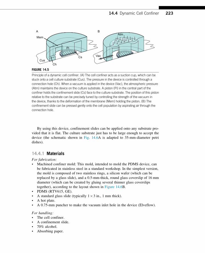
FIGURE 14.5
Principle of a dynamic cell confiner. (A) The cell confiner acts as a suction cup, which can be
stuck onto a cell culture substrate (Cus). The pressure in the device is controlled through a
connection hole (Ch). When a vacuum is applied in the device (Vac), the atmospheric pressure
(Atm) maintains the device on the culture substrate. A piston (Pi) in the central part of the
confiner holds the confinement slide (Cs) face to the culture substrate. The position of this piston
relative to the substrate can be precisely tuned by controlling the strength of the vacuum in
the device, thanks to the deformation of the membrane (Mem) holding the piston. (B) The
confinement slide can be pressed gently onto the cell population by aspirating air through the
connection hole.
22314.4 Dynamic Cell Confiner
• Removable adhesive tape (e.g., Scotch Magic Tape, 3 M).
• A precision vacuum generator or controller (e.g., Elveflow VG1006). Check
before the experiment that you have all the connections plugged into the device.
Sometimes, the culture medium is aspirated into the controller by the vacuum,
which can cause severe damage to the controller. To avoid this, we strongly
recommend placing a security reservoir between the device and the vacuum
controller.
B
A
C
D 85 °C, 30 min
E
F G
Pd
Gs
Glc
Ipm
Cc
Cc
Opm
Si
a
b
b
c
c
d
d
e
e
a
Pn
Bl
Vt
Cn
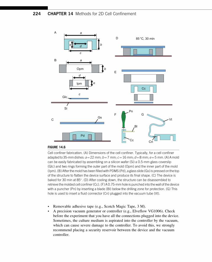
FIGURE 14.6
Cell confiner fabrication. (A) Dimensions of the cell confiner. Typically, for a cell confiner
adapted to35-mmdishes:a¼22 mm;b¼7 mm;c¼16 mm;d¼8 mm;e¼5 mm. (A)Amold
can be easily fabricated by assembling on a silicon wafer (Si) a 0.5-mm glass coverslip
(Glc) and two rings forming the outer part of the mold (Opm) and the inner part of the mold
(Ipm). (B)After themold hasbeen filledwithPDMS (Pd), a glass slide (Gs) is pressed on the top
of the structure to flatten the device surface and produce its final shape. (C) The device is
baked for 30 min at 85�. (D) After cooling down, the structure can be disassembled to
retrieve themoldedcell confiner (Cc). (F)A0.75-mmhole is punched into thewall of thedevice
with a puncher (Pn) by inserting a blade (Bl) below the drilling zone for protection. (G) This
hole is used to insert a fluid connector (Cn) plugged into the vacuum tube (Vt).
224 CHAPTER 14 Methods for 2D Cell Confinement
• Adapted tubing to plug into the vacuum generator, including a 0.51-mm ID tygon
tube (Saint-Gobain) and Stainless Steel Tubing 0.02500 OD (see, e.g., microfluidic
kits, Elveflow) as a connector to plug the tube into the device (see Fig. 14.6G). It is
best to bend the tube to avoid it taking up too much space in the petri dish.
• A sharp pair of tweezers.
14.4.2 Design and FabricationThedesignshown inFigure14.6A is for a35-mmpetridish.Thisparticulargeometryhas
beenoptimized toget aworkingpressureof�10 kPa (�100 mbar),which is sufficient to
handle the device easily, but does not notably change the pressure around the cells. For
other formats of cell cultures, thedevice can be scaledupordown:Theworkingpressure
of the device is independent of the device size if the proportions are respected.
The suction cup device can be molded with PDMS in a simple mold provided the
top and bottom surfaces of the mold are flat enough to get a good optical transpar-
ency. Here, we describe a simple method to make a mold based on the simplest
pieces, which can be done in any workshop.
1. Prepare a mix of PDMS/cross-linker (10/1 w/w) with no bubbles. (If you do not
have a planetary mixer, you can remove bubbles either with a vacuum bell cloche
for 2 h or by centrifuging PDMS for 2 min at 1000 rpm.)
2. Stack the different parts of the mold directly on a (cold) hot plate (Fig. 14.6B).
3. Pour PDMS very slowly into the mold, avoiding bubble formation (Fig. 14.6C).
4. Cover the filled mold with a glass slide, and press on it until there remains only a
residual layer of PDMS between the mold and the slide (Fig. 14.6D).
5. Heat up the hot plate to 85 �C for 30 min (Fig. 14.6D).
6. Cool down the molded part before unmolding. To make unmolding easier, use a
razor blade and isopropanol to reduce adhesion of the PDMS on the mold.
7. Punch the inlet hole with the 0.75-mm puncher as shown in Figure 14.6 F.
14.4.3 Handling1. At least 1 h before the experiment, incubate the confinement slide in the cell
culture medium that will be used for the experiment to equilibrate the PDMS
with the medium. The structured side (PDMS side) of the slide should face
upward. Be careful not to lose the orientation of the slide during manipulation;
it can be difficult to recover. Note that PDMS absorbs small hydrophobic
molecules from the medium. So, if drugs are used in the experiment, these drugs
have to be present during this incubation step.
2. Before the experiment, clean the cell confiner with 70% alcohol, and dry it
carefully with absorbing paper. Be careful not to leave the device in contact with
the alcohol for a long time, or it will absorb the alcohol and become toxic to cells.
3. Clean the bottom face of the device with removable adhesive tape to remove
dust particles.
22514.4 Dynamic Cell Confiner
4. Plug the device into the controllable vacuum source, and tune the controller to
�3 kPa (�30 mbar). At this pressure, and with a good seal, the device sticks
to the substrate, but the confinement slide does not yet touch the cells.
5. Prepare an absorbing paper to dry the back side of the confinement slide.
6. Pick up the confinement slide with tweezers, and dry its back side on the
absorbing paper by placing it onto the paper. (If the back side is not totally dry, it
will not stick onto the device and can be lost during handling.)
7. Place the confinement slide onto the piston of the cell confiner, structured side
up. The slide should stick naturally onto the piston.
8. Put the device in contact with the cell culture substrate. Take care not to deform
the device to achieve a good seal of the device cavity. Also, be careful not
to push on the center of the device, or cells could be crushed by the device. After
the device is well sealed, the membrane sustaining the piston should be
slightly deformed. The step of placing the device must be carried out quickly,
otherwise the medium will fill the device and enter the vacuum outlet. If the
medium enters the vacuum tube, the device may not work properly due to the
capillary pressure of the meniscus in the tube. If the medium has entered the
tube by accident, the device and the tube must be cleaned and dried to
avoid the formation of a meniscus in the tube.
9. At this point, cells canbeobservedbefore confinement.Thepetri dishwill notmove
during theconfinementoperation, andseveral cells canbeobservedsimultaneously.
10. To confine cells, slowly decrease the pressure down to �10 kPa (�100 mbar).
By observing the cells during this time, one should see the confinement slide
touching cells at approximately �5 kPa.
11. Confinement can be released if the pressure is increased back to �3 kPa.
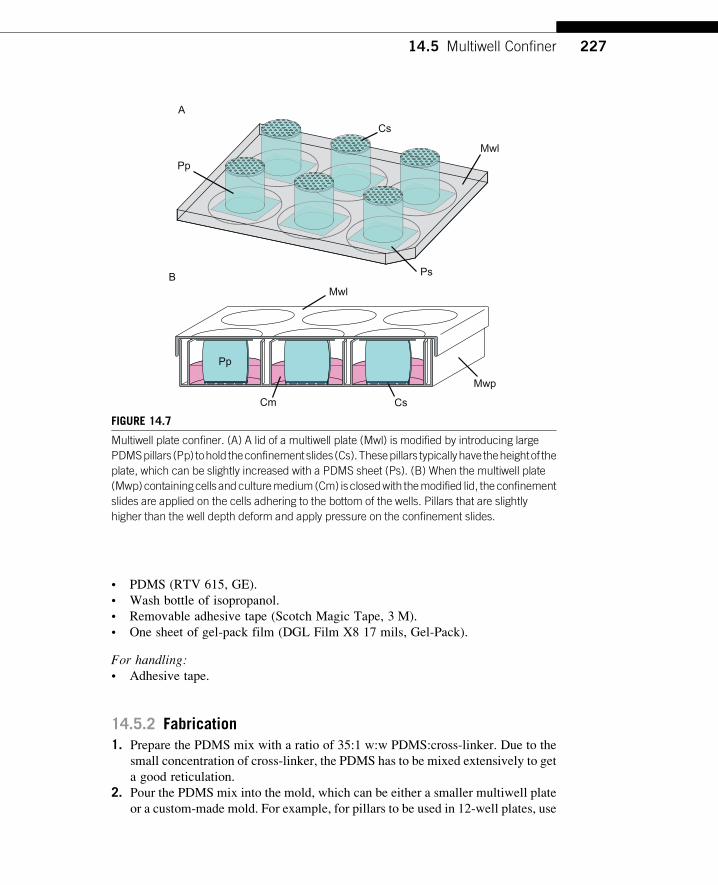
14.5 MULTIWELL CONFINERIf a large amount of confined cells or multiple conditions are required, a modified
multiwell plate can be used to apply confinement slides on cells (Fig. 14.7). In this
case, it is not the force induced by a vacuum that holds the slide on the cells, but the
pressure induced by the deformation of a soft pillar. In this case, big PDMS pillars are
stuck on the lid of the multiwell plate and hold the confinement slides.When the lid is
closed, the pillars push the confinement slides onto the culture substrate and confine
the cells. Many wells can be processed simultaneously, and confinement slides of
larger surfaces can be used; however, the speed of confinement is not controlled,
and it is not convenient to observe what happens during the confinement application.
For this reason, this method is not applicable to the study of short-time events. In
contrast, it is well adapted to long-term experiments and molecular analysis (e.g.,
overnight time-lapse imaging, immunofluorescence).
14.5.1 MaterialsFor fabrication:• A 12 (or 6) well multiwell plate (TPP).
• A 48 (or 12) well multiwell plate.
226 CHAPTER 14 Methods for 2D Cell Confinement
• PDMS (RTV 615, GE).
• Wash bottle of isopropanol.
• Removable adhesive tape (Scotch Magic Tape, 3 M).
• One sheet of gel-pack film (DGL Film X8 17 mils, Gel-Pack).
For handling:• Adhesive tape.
14.5.2 Fabrication1. Prepare the PDMS mix with a ratio of 35:1 w:w PDMS:cross-linker. Due to the
small concentration of cross-linker, the PDMS has to be mixed extensively to get
a good reticulation.
2. Pour the PDMS mix into the mold, which can be either a smaller multiwell plate
or a custom-made mold. For example, for pillars to be used in 12-well plates, use
Cs
Mwl
Pp
Ps
A
CsCm
Mwp
MwlB
Pp
FIGURE 14.7
Multiwell plate confiner. (A) A lid of a multiwell plate (Mwl) is modified by introducing large
PDMSpillars (Pp) tohold theconfinementslides(Cs).Thesepillars typicallyhave theheightof the
plate, which can be slightly increased with a PDMS sheet (Ps). (B) When the multiwell plate
(Mwp)containingcells andculturemedium(Cm) isclosedwith themodified lid, theconfinement
slides are applied on the cells adhering to the bottom of the wells. Pillars that are slightly
higher than the well depth deform and apply pressure on the confinement slides.
22714.5 Multiwell Confiner
a 24-well plate as mold and fill themwith PDMS. Pour the PDMS in excess, leave
it in the vacuum bell cloche to get rid of bubbles, and carefully close with the
lid of the plate avoiding bubble creation. For confinement slides including PAM
gels, which have a higher thickness, spacers of appropriate thickness can be
stuck on the plate lid to reduce the thickness of the final pillars.
3. A small amount of isopropanol will help get the pillars out of the mold. After
unmolding and cleaning, the pillars should be soft and sticky.
4. Clean the pillars carefully with isopropanol.
5. On the multiwell plate lid, place a gel-pack sheet on each well position in order to
raise the pillars slightly.
6. Place the pillars on the gel-pack sheet at the center of each well position. Clean
pillars will stick naturally. You can clean the PDMS and gel-pack sheet before
use with the adhesive tape to remove dust.
7. Now the lid is ready to be used.
14.5.3 Handling1. Place one confinement slide on each pillar of the modified lid.
2. Optional: sterilize the lid under UV (365 nm).
3. Optional: incubate the pillars in culture medium to equilibrate the PDMS.
4. Gently close the multiwell plate with the modified lid.
5. While pushing on the lid, fix the lid to the multiwell plate with adhesive tape.
During this step, avoid moving the lid laterally: This will shear cells and kill
them. Pull on the adhesive tape while applying it to the closed plate to put the
plate under tension.
6. Verify under a microscope that the cells are well confined.
14.6 DISCUSSIONIn this chapter, we have discussed how to confine cells in between two parallel surfaces
separated by a defined gap in a reversible manner. Alternatively, we explained an ad-
aptation of the method to confine cells below a soft PAM gel of controlled stiffness.
However, since the twosurfacescanbe treated independently, andbecause the treatment
of the confinement slides can be very versatile, this method is not limited to these two
configurations in its principles; an infinity of confinement configuration can be imag-
ined. The method can be easily combined with others to build more complex environ-
ments for specific studies. For the geometric confinement, for example, the flat roof can
be replaced by more complex geometric features by using advanced photolithography
methods (see del Campo&Greiner, 2007). Thus, it might be possible to introduce var-
ious textures or restrictions into the geometric landscape of the cell environment. An-
other parameter that canbevaried is the level of adhesion.This canbedonebymixing in
a radiometric manner pLL-g-PEGwith pLL-g-PEG-RGD, which is a modified version
of pLL-g-PEG modified with the RGD motif and is responsible for integrin-mediated
adhesion (see Barnhart, Lee, Keren, Mogilner, & Theriot, 2011). In this case, the
228 CHAPTER 14 Methods for 2D Cell Confinement
adhesion level of cells can be modulated independently on both sides of the cell. Con-
finement can also be combined with other methods. For example, it is possible to print
adhesive micropatterns on the bottoms of the wells to restrict geometric cell adhesion.
This allows a more reproducible organization of the cell under confinement (see
Azioune, Carpi, Tseng, Thery, & Piel, 2010).
GENERAL CONCLUSION
Confinement parameters are taking on increasing importance in cell biology studies,
and tools that allow the control of the different confinement parameters indepen-
dently while remaining simple enough to be used in a biological routine are crucial.
We described in this chapter a versatile way to confine a population of cells in a con-
trolled environment (geometry, stiffness, adhesion, etc.), which is easily combinable
with specific observation techniques and molecular biology protocols. We hope that
these protocols will help the community answer certain questions and will lead to
new and innovative ideas about how to study cells in complex environments.
ReferencesAzioune, A., Carpi, N., Tseng, Q., Thery, M., & Piel, M. (2010). Protein micropatterns:
A direct printing protocol using deep UVs. Methods in Cell Biology, 97, 133–146.Barnhart, E. L., Lee, K. C., Keren, K., Mogilner, A., & Theriot, J. A. (2011). An adhesion-
dependent switch between mechanisms that determine motile cell shape. PLoS Biology,9(5), e1001059.
Boudou, T., Ohayon, J., Picart, C., & Tracqui, P. (2006). An extended relationship for the char-
acterization of Young’s modulus and Poisson’s ratio of tunable polyacrylamide gels.
Biorheology, 43, 721–728.del Campo, A., & Greiner, C. (2007). SU-8: A photoresist for high-aspect-ratio and 3D sub-
micron lithography. Journal of Micromechanical Microengineering, 17, R81–R95.Justice, B. A., Badr, N. A., & Felder, R. A. (2009). 3D cell culture opens new dimensions in
cell-based assays. Drug Discovery Today, 14(1–2), 102–107.Lancaster, O. M., Le Berre, M., Dimitracopoulos, A., Bonazzi, D., Zlotek-Zlotkiewicz, E.,
Picone, R., et al. (2013). Mitotic rounding alters cell geometry to ensure efficient bipolar
spindle formation. Developmental Cell, 25(3), 270–283.Le Berre, M., Aubertin, J., & Piel, M. (2012). Fine control of nuclear confinement identifies a
threshold deformation leading to lamina rupture and induction of specific genes. Integra-tive Biology, 4(11), 1406–1414.
Le Berre, M., Liu, Y.-J., Hu, J., Maiuri, P., Benichou, O., Voituriez, R., et al. (2013). Geomet-ric friction directs cell migration, unpublished.
Mitrossilis, D., Fouchard, J., Pereira, D., Postic, F., Richert, A., Saint-Jean, M., et al. (2010).
Real-time single-cell response to stiffness. Proceedings of the National Academy ofSciences of the United States of America, 107(38), 16518–16523.
Velve-Casquillas, G., Le Berre, M., Piel, M., & Tran, P. T. (2010). Microfluidic tools for cell
biological research. Nano Today, 5(1), 28–47.
229References