Embed Size (px)
Citation preview
G A S F I R E D H I G H E F F I C I E N C Y /C O N S D E N S I N G U L T R A L O W N O x B O I L E R
S I N G L E U N I T O U T P U T 1 2 0 k W
I N S T R U C T I O N S F O R I N S T A L L A T I O N ,S E R V I C I N G & O P E R A T I O N
STRA
TA2
2
STRATA2Index
page section
3 . . . . . . . . .1.0 General1.1 Product Description1.2 Certification Details
3-5 . . . . . .2.0 Product Description
6 . . . . . . . . .3.0 Technical Details3.1 Technical Data
7 . . . . . . . . .3.2 Critical Dimensions
8 . . . . . . . . .3.3 System Guidance3.4 Flue Options4.0 Appliance Installation
Requirements4.1 Statutory Requirements
8-9 . . . . . .4.2 Boiler Position
9-15 . . . .4.3 Flue Options &Terminal Position
15 . . . . . . .4.4 Ventilation Requirements
16-17 . .4.5 Hydraulic System Design
17 . . . . . . .4.6 Gas Supply4.7 Electrical Supply
18 . . . . . . .5.0 Installation Instructions5.1 Unpacking the Boiler5.2 Positioning the Boiler5.3 Air Supply &
Exhaust Connections5.4 Gas Connection
19 . . . . . . .5.5 Water Connections5.6 Condense Waste
Connections5.7 Electrical Connections -
General5.7.1 Connecting the
Power Supply
20 . . . . . . .5.7.2 Connecting of System Safety Interlocks
20-23 . .5.7.3 Connecting of System Safety InterlocksConnection Diagrams
24 . . . . . . .5.7.4 Electrical Wiring Diagrams
25 . . . . . . .5.7.5 Connecting Remote Fault Alarms
5.8 Connecting Additional Boilers
5.8.1 Connecting Third, Fourth, Fifth, Sixth, Seventh and Eighth Units
page section
25 . . . . . . .5.8.2 Boiler Manager RVA 47 Installation Procedure(Normally Factory Fitted)
26 . . . . . . .5.8.3 Mixing Valve Controller RVA 46 Installation Procedure
5.9 Connecting a Condensate Pump
27 . . . . . . .5.9.1 Condensate Receptacle and Pump - Model No. KHPI
6.0 Commissioning and Testing
6.1 Filling the Boiler
28 . . . . . . .6.2 Appliance OperationLeft Switch Panel
6.2.1 Left Switch Panel6.2.2 Module Control Panels
29 . . . . . . .6.2.3 DIP Switches
30 . . . . . . .6.3 Firing the Appliance6.3.1 Initial Start Up6.4 Setting and Adjusting
the Load
31 . . . . . . .6.4.1 Setting Minimum Load6.4.2 Setting Maximum Load6.4.3 Setting Maximum/
Minimum Load for Upper Module
6.5 Setting for Propane Gas
32 . . . . . . .6.6 Setting Domestic Hot Water
6.7 Switching Offthe Appliance
7.0 Boiler Control Settings
32-33 . .7.1 End User Parameter Settings
33-36 . .7.2 Heating Engineer Parameter Setting
37-38 . .7.3 OEM Parameter Setting
38 . . . . . . .8.0 Maintenance and Inspection
8.1 Inspection
39 . . . . . . .8.2 Maintenance9.0 Fault Diagnosis9.1 Control Panel
39-40 . .9.1.1 Operation Indicator9.1.2 Fault Indicator
41 . . . . . . .9.1.3 System Faults9.2 RVA 47 Fault Indication
42 . . . . . . .10.0 Parts List11.0 Guarantees
3
1.0 general
STRATA2
1.1 general notes
These instructions are intended to assist the installer, commissioning engineer, maintenance engineerand user with the installation, maintenance and usage of the Strata 2-120 gas fired condensing boiler.
Please read this manual fully before commencing the installation of the appliance. MHS Boilers Ltd shallnot be responsible for any damage resulting from failure to carefully observe the instructions given.
The Strata 2-120 must only be installed by persons deemed to be competent i.e. Corgi Registered. Thismanual must be handed to the user following completion of the installation.
1.2 certification details
The Strata 120-2 complies with all relevant European Directives and has been independently certifiedto comply with the requirements of prEN 483 for use in GB and IE with Gas Category II2H3P.
(Natural gas G20 @ 20 mbar inlet pressure).
The flue classification (depending upon the required flue option) is either B23; C13X; C33X; C43X;C53X; C63X; C83X.
CE0063AT3426-98
2.0 product
descriptionThe Strata 2-120 boiler is a gas-fired, fully condensing floor standing appliance with a fully modulating
output of 12.2 to 119.7 kW at 30ºC return water temperature. The appliance may be used singularly or inmultiples serving the needs of LTHW systems up to a maximum flow temperature of 85ºC.
Each Strata 2-120 boiler incorporates two modules, each module accommodates its own burner,combustion fan, gas valve, ignition/ionisation, electrode and burner control with safety circuits.
Each module contributes 50% of the total output, and can be operated independently. Each heatexchanger has a modulating capacity of 20% to 100%. If a fault should occur with one of the burner/heatexchanger modules, the other will continue to operate.
The boiler includes, as standard, matched modulating speed pumps which automatically adjust theprimary flow rate for the heat exchangers to (where possible) maintain the design temperature difference.The pumps have residual duty to convey the boiler mass flow rate to the installers system low loss manifold,ensuring correct flow rates through the boiler at all times and reduces installer involvement in this critical area.
The Strata 2-120 incorporates comprehensive microprocessor controls. A RVA47 (CLI) cascademanager is used to translate the heat demand of the installation into a boiler load for each module. Thefirst RVA47 (CLI) manager has the potential to control up to four modules (burner/heat exchangers) inmodulating/cascading fashion. Therefore when installing Strata 2-120 boiler in twin form, all serving thesame system, an RVA47 (CLI) controller is only required and supplied in the first boiler.
The RVA47 (CLI) controller in boiler no.1 is always the ‘master’ and every subsequent controller mustbe set as a ‘slave’.
In addition to the RVA47 (CLI) controller, each Strata 2-120 boiler incorporates individual burner/heatexchanger safety controls which provide the essential safety functions of burner ignition and flamemonitoring, overheat cut off devices for excessive water or flue gas temperature, an LCD display screento indicate run or fault status codes, and individual burner on/off switches.
Room Sealed OptionWhen required, the Strata 2-120 boiler, may be installed as a room sealed appliance, taking air for
combustion from outside the building. This option is recommended for installations where air from withinthe building may be contaminated with oxidising agents, which occur in appliances such as swimming poolplant rooms, dry cleaners and in various manufacturing and industrial process environments etc.
4
STRATA22.0 product description (contd)
Extended Flue Lengths and Difficult Flue RoutesThe excess fan pressure from the combustion system is in the order of 100Pa which allows the
appliance to be exhausted using small diameter flue components over long distances or awkward routes,which allows a considerable degree of flexibility in boiler siting.
As the efficiency of this unit is extremely high, high grade plastic flue components can be utilisedbecause the temperature of the flue gas will at all times remain below 80ºC. (To protect the plasticdischarge pipe against excessive temperatures, a safety thermostat is employed set at 80ºC, which is fittedinside the plastic discharge pipe in the unit, immediately above the upper heat exchanger).
Note: These flue components are available exclusively from MHS.
The Strata 2-120 includes a wealth of enhanced operating facilities and features as standard:
Floor mounted with compact dimensions (provides maximum heat from a minimalfootprint).
Fully modulating heat output: The output is fully variable across the twin burner/heatexchanger arrangement providing a 10:1 turn down ratio, sliding between 10% and 100% of outputwhich automatically and instantly adjusts to meet the needs of the system. The percentage of powerat any given time may be dictated by flow temperature, outside air temperature, room temperature,stored domestic hot water temperature or a combination of these.
Fully condensing stainless steel heat exchanger. The Strata 2-120 boiler features a heatexchanger which deliver exceptional heat transfer, and is fabricated from corrosion resistant, long life,stainless steel. The uniquely designed Spiranox heat exchanger will return operating efficiencies of upto 105% nett (95.5% gross) with a return water temperature of 30ºC.
Extremely low harmful emissions. The boiler utilises 100% premixed gas/air fed at positivepressure to the metal fibre sheathed radiant burners. The optimum amount of gas/air is mixed beforethe combustion fan, and then blown into the burner.
Single/double heat exchanger operation for maximum flexibility of operation. A spring loaded non-return valve has been fitted in the air intake to the combustion fan, preventing fluegases from a firing module from entering the air intake of the non firing module. Also a hydraulic non-return valve is fitted in each heat exchanger return pipe to prevent circulation of water if one of theheat exchangers is not functioning.
Low CO and NOx emissions. The advanced burner and controls allows extremely clean andefficient combustion to be achieved, which in turn gives extremely low emissions certified inaccordance with DIN 4702, CO 15mg/kWh (14ppm) – Nox 11mg/kWh (8.0ppm).
Accurate variable burner output control. The premix fans have very accurate speed controlwhich allows precise control over combustion air volumes. This system facilitates great accuracy andinstantly provides variable burner output. The nature of the variable rate fans allows, in the case of alower heat demand, the fan to run at a slower speed, resulting in lower power consumption.
Each boiler incorporates LCD display screens to display current operational status and operational parameters. Each RVA controller provides cascade modulating burner output control,hours run counters for each burner and programmable lead/lag sequencing.
5
STRATA22.0 product description (contd)
The ‘master’ RVA47 (CLI) controller provides:• Overall modulating output in accordance with the demands of the system.• Inbuilt weather compensation giving direct-on-boiler VT control if required.• Remote stored domestic hot water temperature control• Domestic hot water primary pump or diverter valve control. (2 Amps max)• Heating system pump control. (2 Amps max)• Inbuilt heating system time control with 35 on and 35 off programmable set points within 7 days.• Inbuilt DHW time control with 3 on and 3 off sets points per day.• An option to control the boiler/s from external 0-10V input, or volt free switching.• Programmable frost protection.• The additional option to connect remote control devices.• The additional option to connect VT zone controllers. (RVA46)
Designed for Ease of MaintenanceThe appliance has been designed and engineered to be easy to maintain, with most major service
operations being quick and easy to complete with the minimum of tools.Each module can operate independently, without affecting the service of the other modules within
the system.To facilitate the annual inspection and cleaning of the syphon, there is a rinsing pipe at the back of the
unit. The condense is led through a built-in syphon to a plastic connection at the back, where a suitableconnection can be made to the termination point.
Operational Data LoggingEach burner assembly has a data logging facility to record operational actions, which can be accessed
via an RS232 communication from a PC. This facility provides a useful service tool as it allows a record ofoperation to be viewed and any faults to be identified.
6
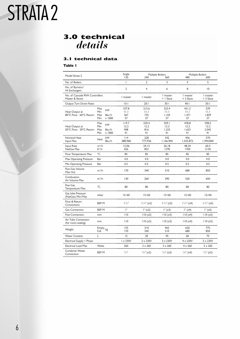
STRATA23.0 technical
details3.1 technical data
Table 1
Model Strata 2
No. of Boilers
No. of Burners/Ht Exchangers
No. of Cascade RVA ControllersMaster & Slaves
Output Turn Down Ratio
MaxkW
Heat Output at Min80°C Flow - 60°C Return Max Btu/h
Min x 1000
MaxkW
Heat Output at Min50°C Flow - 30°C Return Max Btu/h
Min x 1000
Nominal HeatNett
kWInput Max Btu/h
Input Rate m3/hNatGas Max ft3/h
Flow Temperature Max °C
Max Operating Pressure Bar
Min Operating Pressure Bar
Flue Gas Volumem3/h
Max Hot
Combustionm3/h
Air Volume Max
Flue Gas°C
Temperature Max
Gas Inlet Pressurembar
(NatGas) Min/Max
Flow & ReturnBSP-M
Connections
Gas Connection BSP-M
Flue Connection mm
Air Tube Connectionmm
(for room sealing)
WeightEmpty
kgFull
Water Content L
Electrical Supply 1 Phase
Electrical Load Max Watts
Condense WasteBSP-M
Connection
Single120
1
2
1 master
10:1
107.811.136737
119.712.240841
114388,968
12.06426
85
4.0
0.5
170
130
80
15/60
11/4"
1"
110
110
155170
15
1 x 230V
260
3/4"
240
2
4
1 master
20:1
215.611.173537
239.412.281641
228777,936
24.12852
85
4.0
0.5
340
260
80
15/60
11/4" (x2)
1" (x2)
110 (x2)
110 (x2)
310340
30
2 x 230V
2 x 260
3/4" (x2)
360
3
6
1 master+ 1 Slave
30:1
323.411.11,103
37
359.112.21,225
41
3421,166,904
36.181278
85
4.0
0.5
510
390
80
15/60
11/4" (x3)
1" (x3)
110 (x3)
110 (x3)
465510
45
3 x 230V
3 x 260
3/4" (x3)
480
4
8
1 master+ 2 Slave
40:1
431.211.11,471
37
478.812.21,633
41
4561,555,872
48.241704
85
4.0
0.5
680
520
80
15/60
11/4" (x4)
1" (x4)
110 (x4)
110 (x4)
620680
60
4 x 230V
4 x 260
3/4" (x4)
600
5
10
1 master+ 3 Slave
50:1
53911.11,839
37
598.512.22,042
41
5701,944,840
60.32130
85
4.0
0.5
850
650
80
15/60
11/4" (x5)
1" (x5)
110 (x5)
110 (x5)
775850
75
5 x 230V
5 x 260
3/4" (x5)
Multiple Boilers Multiple Boilers
STRATA2
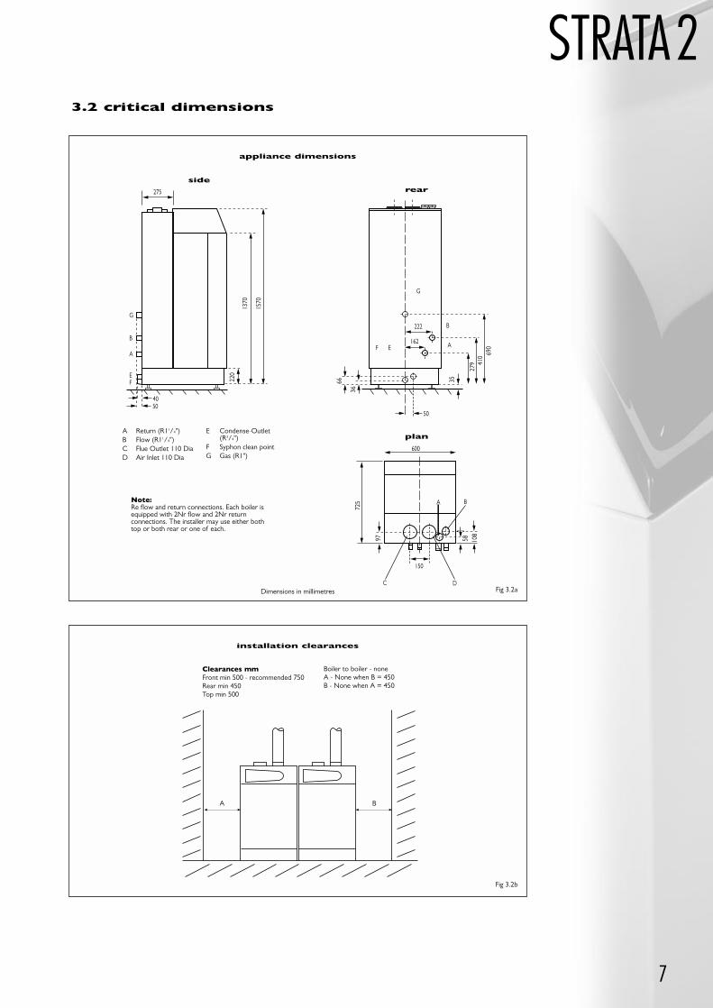
7
600
150
725
97 108
58
A
C
B
D
222
162
50
690
410
279
3566
36F E
G
B
A
4050
275
1570
1370
220
G
B
A
EF
plan
rearside
A Return (R11/4")B Flow (R11/4")C Flue Outlet 110 DiaD Air Inlet 110 Dia
E Condense-Outlet(R3/4")
F Syphon clean pointG Gas (R1")
Dimensions in millimetres
Note:Re flow and return connections. Each boiler isequipped with 2Nr flow and 2Nr returnconnections. The installer may use either bothtop or both rear or one of each.
Clearances mmFront min 500 - recommended 750Rear min 450Top min 500
A B
Boiler to boiler - noneA - None when B = 450B - None when A = 450
3.2 critical dimensions
appliance dimensions
installation clearances
Fig 3.2a
Fig 3.2b
8
STRATA23.3 system guidance
In summary, the Strata is designed for use with a sealed pressurised hydronic circuit operating upon adesign temperature difference of 20ºC. The integral primary pumps have approximately 1m head availableto overcome a primary loop incorporating a low velocity mixing header. Full details regarding suitablesystem designs are given in section 4.3.
3.4 flue options
The Strata 2-120 may be used with either an open or room sealed flue and air system. Approximately100Pa is available as residual flue pressure at the exit from the appliance. Full details regarding fluespecification are given in section 4.3.
4.0 appliance
installation requirements4.1 statutory requirements
Gas Safety (Installation and Use) Regulations (Current Issue)It is the law that all gas appliances are installed by a registered person, in accordance with the above
regulations. Failure to install appliances correctly could lead to prosecution. It is in your own interest, andthat of safety, to ensure that the law is complied with.
In addition to the above regulations, this appliance must be installed in accordance with the current IEEWiring Regulations for electrical installation, (BS 7671), Local Building Regulations, the Building Standards(Scotland) (Consolidation) Regulations, Bye laws of the Local Water Undertaking and Health and SafetyDocument No. 635 ‘The Electricity at Work Regulations 1989’.
It should also be in accordance with the relevant recommendations in the current editions of thefollowing British Standards and Codes of Practice, plus any others that are relevant to the proposedinstallation: BS5449, BS5546, BS5440:1, BS6798, BS6891, BS6644, BS6880, IGE/UP/2, IGE/UP/7, & IM11.Clean Air Act Memorandum on Chimney Heights.
Important Note: Manufacturer’s instructions must NOT be taken in any way as overriding statutory obligations.
4.2 boiler position
The following considerations must be observed when siting the Strata 2-120:The boiler is not suitable for external installation. The position selected for installation should be within
the building, unless otherwise protected by a suitable enclosure, and MUST allow adequate space forinstallation, servicing, and operation of the appliance, and for air circulation around it. (Refer to figure 4.3e).In a multiple set-up (modular set-up), the sides of the units may be placed against one another, without anyroom in between.
This position MUST allow for a suitable flue system and terminal position (Refer to sections 4.3). Aconnection to a suitable termination point for the discharge of condense must be available . If this is notpresent, a condensation pump with an elevation level of 5 metres may be fitted to the appliance. The Strata2-120 must be installed on a flat horizontal floor which is capable of supporting the boiler and any ancillaries(circa 200kg).
If the appliance is to be fitted in a timber framed building it should be fitted in accordance with theBritish Gas publication ‘Guide for Gas Installations In Timber Frame Housing’, Reference DM2. If in doubt,advice must be sought from the Gas Supplier.
If the appliance is to be installed in a room containing a bath or a shower, any electrical switch orcontrol utilising mains electricity must be so situated that it cannot be touched by a person using the bathor shower. Attention is drawn to the requirements of BS7671 (the current I.E.E. Wiring Regulations), andin Scotland the electrical provisions of the Building Regulations applicable in Scotland.
A compartment used to enclose the appliance MUST be designed and constructed specifically for thispurpose. An existing cupboard, or compartment, may be used provided it is modified accordingly. BS5376:2 gives details of the essential features of cupboard/compartment design, including airing cupboards.
9
4.2 boiler position (contd)
STRATA2Where installation will be in an unusual location, special procedures may be necessary. BS6798 gives
detailed guidance on this aspect.The unit cannot be used in the vicinity of chlorine, halogen or sulphur as may be the case in
environments such as swimming pools, coolant filling stations etc. In such cases the appliances MUST beroom sealed to take air for combustion from outside of the building.
DN100 PPS tube x 1000mm DN100 PPS bend x 90° DN100 PPS bend x 45° DN100 wall bracket DN125 PPS tube x 1000mm DN125 PPS bend x 90° DN125 PPS bend x 45° DN125 wall bracket DN150 PPS tube x 1000mm DN150 PPS bend x 90° DN150 PPS bend x 45° DN150 PPS tee with 45° branch DN100 x 125 PPS increaser DN125 x 150 PPS increaser DN150 wall bracket 100/100 to 100/150 concentric adaptor
100/150 concentric tube x 1000mm 100/150 concentric bend x 90° 100/150 concentric bend x 45° 100/150 concentric horizontal terminal effective
length 975mm 100/150 concentric vertical terminal effective
length 500mm DN100 flat roof flashing DN100 pitched roof flashing DN125 flat roof flashing DN125 pitched roof flashing DN150 flat roof flashing DN150 pitched roof flashing Flat roof for 100/150 concentric terminal Adjustable pitched roof flashing for 100/150
concentric terminal
4.3 flue options &
terminal positionThe Strata 2 has an excess pressure combustion system that allows the appliance to be exhausted over
extended distances using small OD flue components.The flue gas temperature is extremely low (typically the same as the flow water temperature), which
allows the use of easy to install PPS (polypropylene) flue pipe and fittings.The appliance can take combustion air from the room in which it is installed (conventional application)
or can be room sealed (fanned balanced flue) using a concentric flue arrangement of a 100mm PPS flueduct within a 150mm galvanised metal air duct, finished in off-white RAL 7035. A full range of flue pipe andair duct components including roof and wall terminals is available from MHS Boilers.
list of flue components
calculating flue resistance
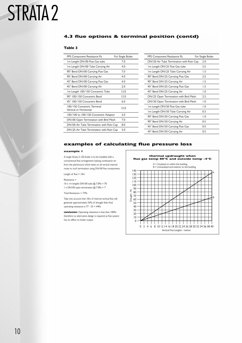
The excess pressure available for overcoming the frictional resistance of a flue system is 100 P.a. Thetable of flue component resistances will assist the designer in calculating total flue system frictional loss.
If the total installed flue system resistance exceeds 100 P.a., then the result will be a reduction in boileroutput. Reference to the “Effect of Flue System Resistance On Boiler Output”, graphs will assist. If theresistance of a proposed flue system has an unacceptable effect on boiler output, then a larger diameterflue tube should be selected. Thermal up-draught is generated in a vertical flue system, reducing theresistance of the system. Reference to the “Thermal Up-draught Graph” will provide a figure in P.a., whichmay be deducted from the total calculated flue system resistance.
Note: Does not apply to horizontal sections of a flue system.
10
STRATA24.3 flue options & terminal position (contd)
PPS Component Resistance Pa For Single Boiler
1m Length DN100 Flue Gas tube 7.0
1m Length DN100 Tube Carrying Air 4.0
90° Bend DN100 Carrying Flue Gas 7.0
90° Bend DN100 Carrying Air 4.0
45° Bend DN100 Carrying Flue Gas 4.0
45° Bend DN100 Carrying Air 2.0
1m Length 100/150 Concentric Tube 12.0
90° 100/150 Concentric Bend 12.0
45° 100/150 Concentric Bend 6.0
100/150 Concentric Terminal15.0
Vertical or Horizontal
100/100 to 100/150 Concentric Adaptor 2.0
DN100 Open Termination with Bird Mesh 7.0
DN100 Air Tube Termination with Rain Cap 8.0
DN125 Air Tube Termination with Rain Cap 5.0
PPS Component Resistance Pa For Single Boiler
DN150 Air Tube Termination with Rain Cap 2.0
1m Length DN125 Flue Gas tube 2.5
1m Length DN125 Tube Carrying Air 1.5
90° Bend DN125 Carrying Flue Gas 2.5
90° Bend DN125 Carrying Air 1.5
45° Bend DN125 Carrying Flue Gas 1.5
45° Bend DN125 Carrying Air 1.0
DN125 Open Termination with Bird Mesh 2.5
DN150 Open Termination with Bird Mesh 1.0
1m Length DN150 Flue Gas tube 1.0
1m Length DN150 Tube Carrying Air 0.5
90° Bend DN150 Carrying Flue Gas 1.0
90° Bend DN150 Carrying Air 0.5
45° Bend DN150 Carrying Flue Gas 0.5
45° Bend DN150 Carrying Air 0.5
Table 3
examples of calculating flue pressure loss
1401301201101009080706050403020100
0 2 4 6 8 10 12 14 16 18 20 22 24 26 28 30 32 34 36 38 40
B
A
Vertical Flue Lengths - metres
A = Insulated or within the buildingB = Uninsulated and exterior to the building
Dra
ught
- P
a
example 1
A single Strata 2-120 boiler is to be installed with a
conventional flue arrangement (taking combustion air
from the plantroom) which takes an all vertical internal
route to roof termination using DN100 flue components.
Length of flue = 10m
Resistance =
10 x 1m lengths DN100 tube @ 7.0Pa = 70
1 x DN100 open termination @ 7.0Pa = 7
Total Resistance = 77Pa
Take into account that 10m of internal vertical flue will
generate approximately 33Pa of draught then final
operating resistance is 77 - 33 = 44Pa
conclusion: Operating resistance is less than 100Pa
therefore no alternative design is required as flue system
has no effect on boiler output.
thermal updraught whenflue gas temp 80°C and outside temp -5°C
11
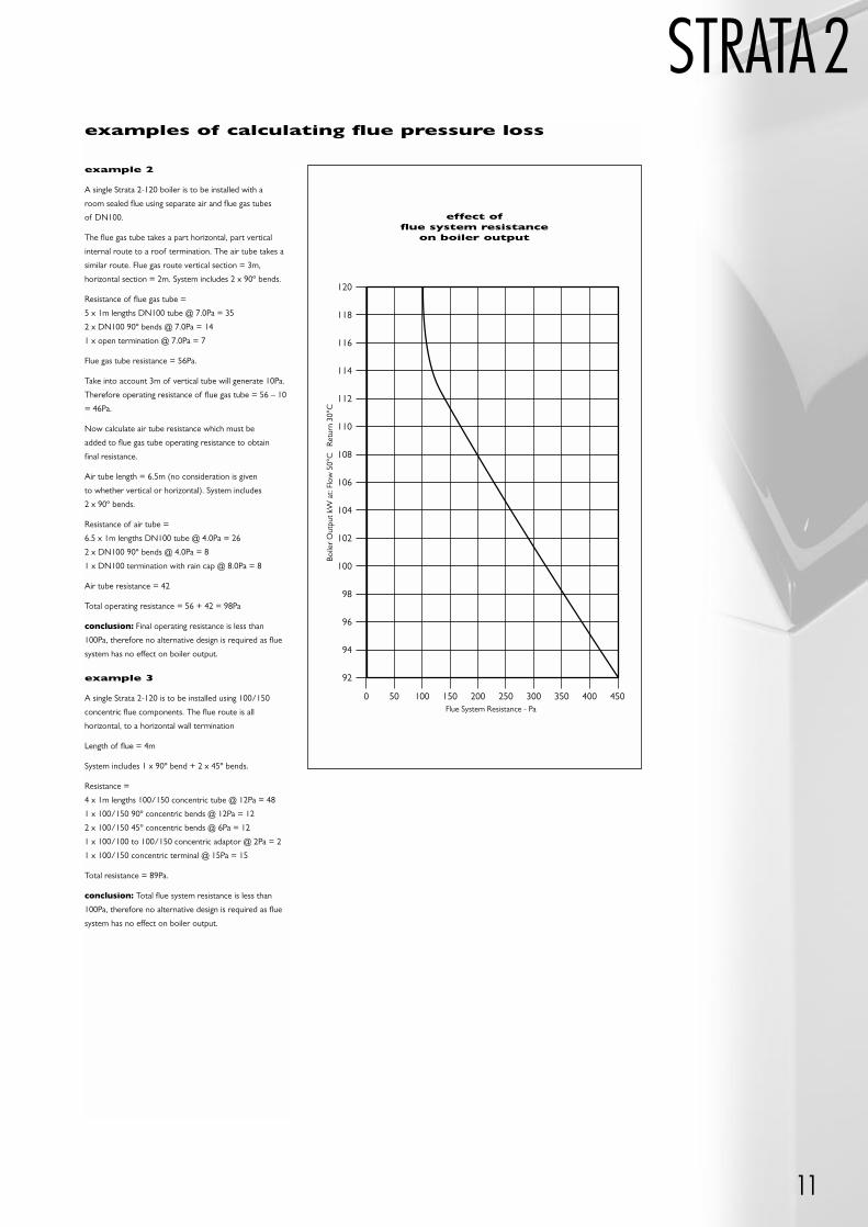
STRATA2example 2
A single Strata 2-120 boiler is to be installed with a
room sealed flue using separate air and flue gas tubes
of DN100.
The flue gas tube takes a part horizontal, part vertical
internal route to a roof termination. The air tube takes a
similar route. Flue gas route vertical section = 3m,
horizontal section = 2m. System includes 2 x 90º bends.
Resistance of flue gas tube =
5 x 1m lengths DN100 tube @ 7.0Pa = 35
2 x DN100 90º bends @ 7.0Pa = 14
1 x open termination @ 7.0Pa = 7
Flue gas tube resistance = 56Pa.
Take into account 3m of vertical tube will generate 10Pa.
Therefore operating resistance of flue gas tube = 56 – 10
= 46Pa.
Now calculate air tube resistance which must be
added to flue gas tube operating resistance to obtain
final resistance.
Air tube length = 6.5m (no consideration is given
to whether vertical or horizontal). System includes
2 x 90º bends.
Resistance of air tube =
6.5 x 1m lengths DN100 tube @ 4.0Pa = 26
2 x DN100 90º bends @ 4.0Pa = 8
1 x DN100 termination with rain cap @ 8.0Pa = 8
Air tube resistance = 42
Total operating resistance = 56 + 42 = 98Pa
conclusion: Final operating resistance is less than
100Pa, therefore no alternative design is required as flue
system has no effect on boiler output.
example 3
A single Strata 2-120 is to be installed using 100/150
concentric flue components. The flue route is all
horizontal, to a horizontal wall termination
Length of flue = 4m
System includes 1 x 90º bend + 2 x 45º bends.
Resistance =
4 x 1m lengths 100/150 concentric tube @ 12Pa = 48
1 x 100/150 90º concentric bends @ 12Pa = 12
2 x 100/150 45º concentric bends @ 6Pa = 12
1 x 100/100 to 100/150 concentric adaptor @ 2Pa = 2
1 x 100/150 concentric terminal @ 15Pa = 15
Total resistance = 89Pa.
conclusion: Total flue system resistance is less than
100Pa, therefore no alternative design is required as flue
system has no effect on boiler output.
examples of calculating flue pressure loss
Flue System Resistance - Pa
120
118
116
114
112
110
108
106
104
102
100
98
96
94
92
0 50 100 150 200 250 300 350 400 450
Boile
r O
utpu
t kW
at:
Flow
50°
C
Ret
urn
30°C
effect offlue system resistance
on boiler output
12
STRATA24.3 flue options & terminal position (contd)
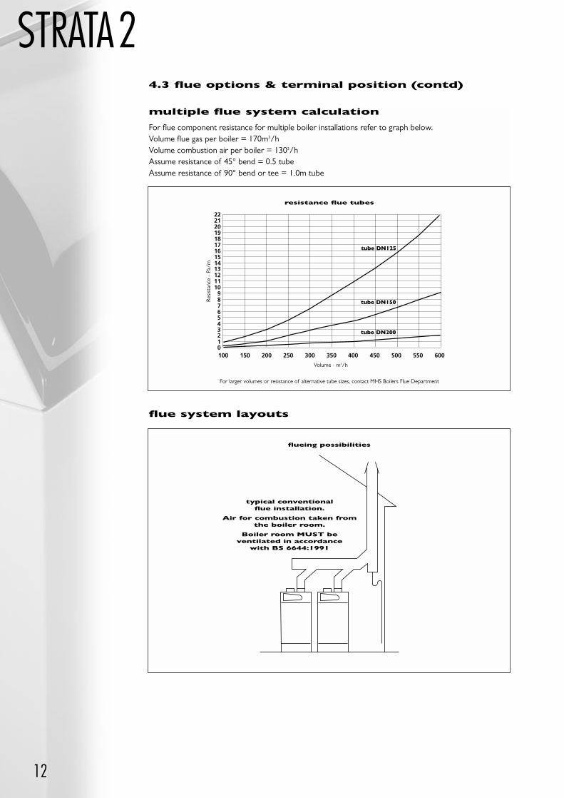
multiple flue system calculation
For flue component resistance for multiple boiler installations refer to graph below.Volume flue gas per boiler = 170m3/hVolume combustion air per boiler = 1303/hAssume resistance of 45° bend = 0.5 tubeAssume resistance of 90° bend or tee = 1.0m tube
150100
222120191817161514131211109876543210
200 250 300 350 400 450 500 550 600
resistance flue tubes
tube DN125
tube DN150
tube DN200
Res
ista
nce
- Pa
/m
Volume - m3/h
For larger volumes or resistance of alternative tube sizes, contact MHS Boilers Flue Department
flueing possibilities
typical conventionalflue installation.
Air for combustion taken fromthe boiler room.
Boiler room MUST beventilated in accordance
with BS 6644:1991
flue system layouts
13
STRATA2
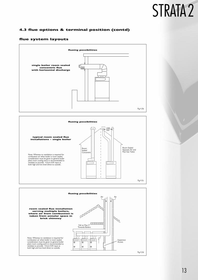
flueing possibilities
single boiler room sealedconcentric flue
with horizontal discharge
flueing possibilities
typical room sealed flueinstallations - single boiler
flueing possibilities
room sealed flue installationserving multiple boilers,
where air from combustion istaken from annular space in
brick chimney
Note: Whereas no ventilation is required forcombustion air when boiler is room sealed,consideration must be given to general boilerplant room cooling and it is recommended toventilate to provide:- 4.5cm/kW input atboth high and low level direct to outside.
RoomSealedConcentric
Room SealedSeparate Air andFlue Gas Tubes
1200min
Note: Whereas no ventilation is required forcombustion air when boiler is room sealed,consideration must be given to general boilerplant room cooling and it is recommended toventilate to provide:- 4.5cm/kW input atboth high and low level direct to outside.
Air Air
Fall on Flue 3°Towards Boilers
InspectionAccess
flue system layouts
4.3 flue options & terminal position (contd)
Fig 4.3b
Fig 4.3c
Fig 4.3d

14
STRATA2Additional Notes for Room Sealed Appliances:
The Clean Air Act Memorandum prevents the use of balanced flue appliances discharging at low levelwhere the total heat input to the plant room exceeds 150kW. Where the Clean Air Act does not preventinstallation, the following rules must be applied.
Note: Detailed recommendations for flue installation are given in BS5440:1
The following points are for general guidance:
The boiler must be installed so that the terminal is exposed to external air.
It is important that the position of the terminal allows free passage of air across it at all times.
It is essential to ensure that products of combustion discharging from the terminal cannot re-enter thebuilding or any other adjacent buildings, through ventilators, windows, doors, other sources of naturalair infiltration, or forced ventilation/air conditioning.
The minimum acceptable dimensions from the terminal to obstructions and ventilation openings arespecified in figure 4.3e.
If the terminal discharges into a pathway or passageway check that combustion products will not causenuisance and that the terminal will not obstruct the passageway.
Where the lowest part of the terminal is fitted less than 2m (78ins) above ground, above a balcony or above a flat roof to which people have access, the terminal MUST be protected by a purposedesigned guard.
Where the terminal is fitted within 850mm (34ins) of a plastic or painted gutter, or 450mm (18ins) of painted eaves, an aluminium shield at least 750mm long must be fitted to the underside of thepainted surface.
The air inlet/flue outlet duct MUST NOT be closer than 25mm (1in) to combustible material.
Note: Under most weather conditions the terminal will emit a plume of steam. This is normal butpositions where this would cause a nuisance should be avoided.
In the case of horizontal flue gas discharge pipes, an angle of 3º must be observed in the direction ofthe boiler (5.0cm for every metre of pipe length) with a fall towards the boiler, to allow condense in theflue gases to return to the unit.
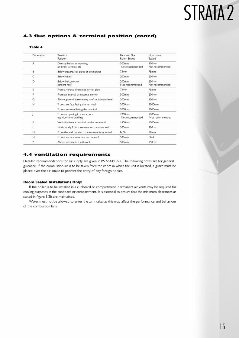
Minimum dimensions of flue terminal positions:
flue terminal positions
H,I
J
PA
G
F D
E AG
P
B,C
F
F
LK
LK
P
N
4.3 flue options & terminal position (contd)
15
STRATA2
4.4 ventilation requirements
Detailed recommendations for air supply are given in BS 6644:1991. The following notes are for generalguidance. If the combustion air is to be taken from the room in which the unit is located, a guard must beplaced over the air intake to prevent the entry of any foreign bodies.
Room Sealed Installations Only:If the boiler is to be installed in a cupboard or compartment, permanent air vents may be required for
cooling purposes in the cupboard or compartment. It is essential to ensure that the minimum clearances asstated in figure 3.2b are maintained.
Water must not be allowed to enter the air intake, as this may affect the performance and behaviourof the combustion fans.
Dimension Terminal Balanced Flue Non room Position Room Sealed Sealed
A Directly below an opening, 300mm 300mmair brick, window etc Not recommended Not recommended
B Below gutters, soil pipes or drain pipes 75mm 75mm
C Below eaves 200mm 200mm
D Below balconies or 200mm 200mm carport roof Not recommended Not recommended
E From a vertical drain pipe or soil pipe 75mm 75mm
F From an internal or external corner 300mm 200mm
G Above ground, intersecting roof or balcony level 300mm 300mm
H From a surface facing the terminal 2000mm 2000mm
I From a terminal facing the terminal 2000mm 2000mm
J From an opening in the carport 1200mm 1200mme.g. door into dwelling Not recommended Not recommended
K Vertically from a terminal on the same wall 1500mm 1500mm
L Horizontally from a terminal on the same wall 300mm 300mm
M From the wall on which the terminal is mounted N/A 50mm
N From a vertical structure on the roof 500mm N/A
P Above intersection with roof 500mm 150mm
4.3 flue options & terminal position (contd)
Table 4
16
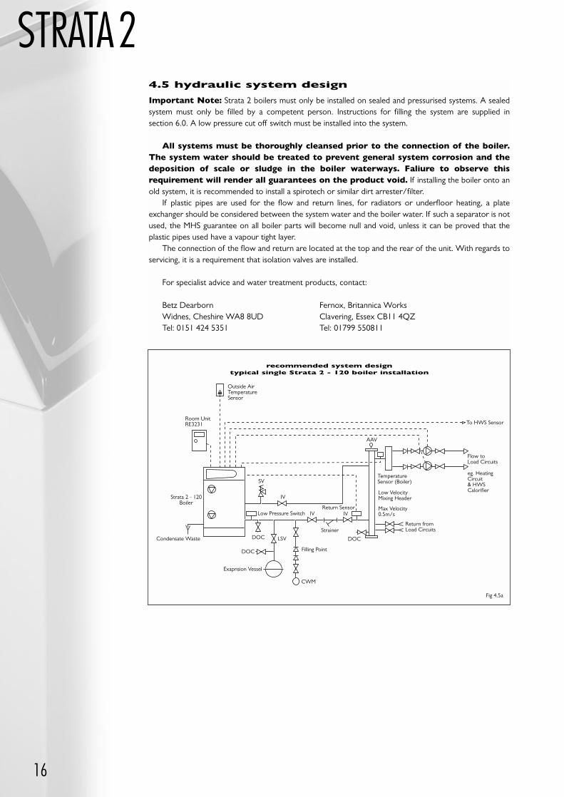
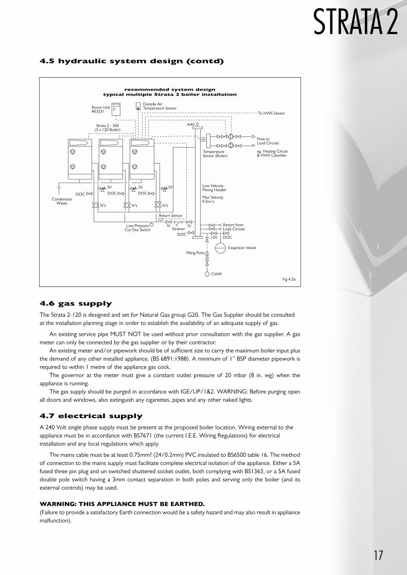
STRATA24.5 hydraulic system design
Important Note: Strata 2 boilers must only be installed on sealed and pressurised systems. A sealedsystem must only be filled by a competent person. Instructions for filling the system are supplied in section 6.0. A low pressure cut off switch must be installed into the system.
All systems must be thoroughly cleansed prior to the connection of the boiler.The system water should be treated to prevent general system corrosion and thedeposition of scale or sludge in the boiler waterways. Faliure to observe thisrequirement will render all guarantees on the product void. If installing the boiler onto anold system, it is recommended to install a spirotech or similar dirt arrester/filter.
If plastic pipes are used for the flow and return lines, for radiators or underfloor heating, a plateexchanger should be considered between the system water and the boiler water. If such a separator is notused, the MHS guarantee on all boiler parts will become null and void, unless it can be proved that theplastic pipes used have a vapour tight layer.
The connection of the flow and return are located at the top and the rear of the unit. With regards toservicing, it is a requirement that isolation valves are installed.
For specialist advice and water treatment products, contact:
Betz Dearborn Fernox, Britannica WorksWidnes, Cheshire WA8 8UD Clavering, Essex CB11 4QZTel: 0151 424 5351 Tel: 01799 550811
AAV
Outside AirTemperatureSensor
Room UnitRE3231
Strata 2 - 120Boiler
Condensate Waste
Low Pressure Switch
Exapnsion Vessel
Filling Point
CWM
DOC
DOC
LSV
IV
SV
IV IV
Strainer
DOC
Return Sensor
Return fromLoad Circuits
TemperatureSensor (Boiler)
Low VelocityMixing Header
Max Velocity0.5m/s
Flow toLoad Circuits
eg. HeatingCircuit& HWSCalorifier
To HWS Sensor
recommended system designtypical single Strata 2 - 120 boiler installation
Fig 4.5a
17
STRATA2
AAV
Outside AirTemperature SensorRoom Unit
RE3231
Strata 2 - 360(3 x 120 Boiler)
CondensateWaste
Low PressureCut Out Switch
Exapnsion VesselFilling Point
CWM
DOC
DOCLSV
IV’s IV’s IV’s
SV SV SV
IV IVStrainer
DOC DOC
Return Sensor
Return fromLoad Circuits
TemperatureSensor (Boiler)
Low VelocityMixing Header
Max Velocity0.5m/s
Flow toLoad Circuits
eg. Heating Circuit& HWS Calorifier
To HWS Sensor
recommended system designtypical multiple Strata 2 boiler installation
DOC
4.6 gas supply
The Strata 2-120 is designed and set for Natural Gas group G20. The Gas Supplier should be consultedat the installation planning stage in order to establish the availability of an adequate supply of gas.
An existing service pipe MUST NOT be used without prior consultation with the gas supplier. A gasmeter can only be connected by the gas supplier or by their contractor.
An existing meter and/or pipework should be of sufficient size to carry the maximum boiler input plusthe demand of any other installed appliance. (BS 6891:1988). A minimum of 1” BSP diameter pipework isrequired to within 1 metre of the appliance gas cock.
The governor at the meter must give a constant outlet pressure of 20 mbar (8 in. wg) when theappliance is running.
The gas supply should be purged in accordance with IGE/UP/1&2. WARNING: Before purging openall doors and windows, also extinguish any cigarettes, pipes and any other naked lights.
4.7 electrical supply
A 240 Volt single phase supply must be present at the proposed boiler location. Wiring external to theappliance must be in accordance with BS7671 (the current I.E.E. Wiring Regulations) for electricalinstallation and any local regulations which apply.
The mains cable must be at least 0.75mm? (24/0.2mm) PVC insulated to BS6500 table 16. The methodof connection to the mains supply must facilitate complete electrical isolation of the appliance. Either a 5Afused three pin plug and un-switched shuttered socket outlet, both complying with BS1363, or a 5A fuseddouble pole switch having a 3mm contact separation in both poles and serving only the boiler (and itsexternal controls) may be used.
WARNING: THIS APPLIANCE MUST BE EARTHED.(Failure to provide a satisfactory Earth connection would be a safety hazard and may also result in appliancemalfunction).
Fig 4.5b
4.5 hydraulic system design (contd)
18
STRATA25.0 installation
intructions5.1 unpacking the boiler
The boiler is delivered in a palletted carton containing the boiler and associated fittings, plus any otheroptional ancillary flue or control components in separate cartons.
The boiler carton contains:
Fully assembled boiler.
The Strata 2-120 is also delivered with the following items:
User manual and operating instructions.
Installation and Servicing instructions for the Engineer.
Built into each unit are the following:
A gas stop cock for each heat module.
Three way return water cut-off.
RVA 47 control unit (master and slave boilers), 1 outside air sensor, 1 flow sensor and 1 return sensor.
The unit must be inspected immediately after delivery. Any damage to the consignments must bereported within 3 days.
To unpack the boiler, carefully cut away the outer packaging and open the carton top. Lift off thebottomless carton. By holding the chassis only lift the appliance away from the palette.
To remove the casing from the boiler:
Remove the two screws on the bottom front edge of the top casing panel.
Remove panel to the front.
5.2 positioning the boiler
Move the appliance to the desired location, making sure that all clearance dimensions as stated insection 3.2 are adhered to. Level the appliance in a vertical position by turning the adjustable feetunderneath the base of the unit. Check that the appliance is in a true vertical position by using a spirit level.Once the appliance is in a true vertical position, the adjustable feet must be secured by locking the nuts.
5.3 air supply and exhaust connections
The unit has two connections, one for the supply of combustion air and the other for the discharge ofthe products of combustion. Each connection is clearly labelled and located at the rear top of the appliance.
5.4 gas connection
The Gas connection is located at the rear of the appliance. The gas supply should be sized, installed,tested and purged in accordance with IGE/UP/1&2.
The connection to the appliance must include a suitable method of disconnection and a gas controlcock must be installed adjacent to the appliance for isolation purposes.
The gas pipe used to supply the appliance must not allow a pressure drop of greater than 1 mbar fromthe meter to the appliance. The nominal inlet working gas pressure measured at the appliance should be20.0 mbar for Nat Gas (G20). The installer should install a pressure test point adjacent to the gas inletconnection. The gas supply line should be purged.
WARNING: Before purging open all doors and windows, also extinguish any cigarettes, pipes and anyother naked lights.
19
STRATA25.5 Water Connections
The central heating flow and return connections are 11/4" BSP male. Two sets of flow and returnconnections are provided and located on the rear top of the appliance and the rear of the appliance. Theinstaller may use both top or both rear connections or one of each for connection of the flow and return pipes.
A suitable safety valve must be installed onto the boiler flow pipe between the boiler and any isolation valve. The boiler flow and return pipes must include a method of disconnection and must includeisolation valves.
5.6 condense waste connections
The condense waste connection is located at the lower rear of the appliance. The condense syphoncleaning point is factory fitted with a heavy grade black plastic cap which MUST NOT BE REMOVED.Operating the appliance with the cap removed from the syphon cleaning point will allow products ofcombustion to be discharged from the cleaning point.
The condense waste connection is a 3/4" BSP male threaded stub fabricated from plastic. The installermust connect to this stub, a condense waste pipe fabricated from plastic tube and fittings (3/4", 22mmoverflow pipe is considered suitable). Only plastic components must be used for the condensationdischarge. Metal pipes are not acceptable due to the acidic nature of the condensate.
The built in syphon allows the unit to be connected directly to a drain system. If any part of thecondense waste pipe is to be run external to the building or is at risk of freezing, then the pipe must besuitable insulated to protect from freezing.
If a suitable drain for accepting the condense waste is not available nearby to and below the boiler (e.g.if the boiler is installed in a basement below ground level), then an (optional extra) condensate receptacleand pump can be installed into the free space at the base of the appliance. This will collect and removecondense water to a remote drain up to 5 metres height difference above the receptacle position.
Note: Blockage of the waste discharge will cause the unit to switch off by means of a built in level switch.
When making the condense waste pipe connection to the boiler, do not use adhesives, it isrecommended to lightly apply a suitable jointing tape (PTFE or similar) and use only light pressure toconnect fittings to the appliance to avoid damage to the condense waste outlet assembly. It isrecommended that the condense waste pipework should include a method of disconnection and cleaning points.
5.7 electrical connections – general
The Strata 2-120 has a number of standard connection points. In addition, a number of panel locationshave been reserved for the installation controller, which can be mounted in the spaces provided afterremoving the blank panels.
At the top of the boiler, behind the controllers, is a connector plate stretching across the entire widthof the boiler, flanked by three cable clamp brackets. All electrical connections are made via plugs andsockets and to avoid mistakes during the connection of the cables, each plug has its own colour.
5.7.1 connecting the power supply
The incoming power supply (230V) must be connected to the black 3 pin Weiland plug located at thefar left hand side of the connectors mounting plate in the top area of the boiler. The unit has a 2-poleon/off switch for the power supply of the entire boiler and all the connected controllers, pumps and valves.
Determine the cross sectional area of the power supply cable and take into account the power usageof the combined components connected to the control units.
In addition each burner module has a single pole-switch to switch off one burner unit while the secondunit may continue to function. The main switch is protected by a 6.3 AT fuse.
CAUTION: The main power supply for the boiler must have a higher fuse value.
20
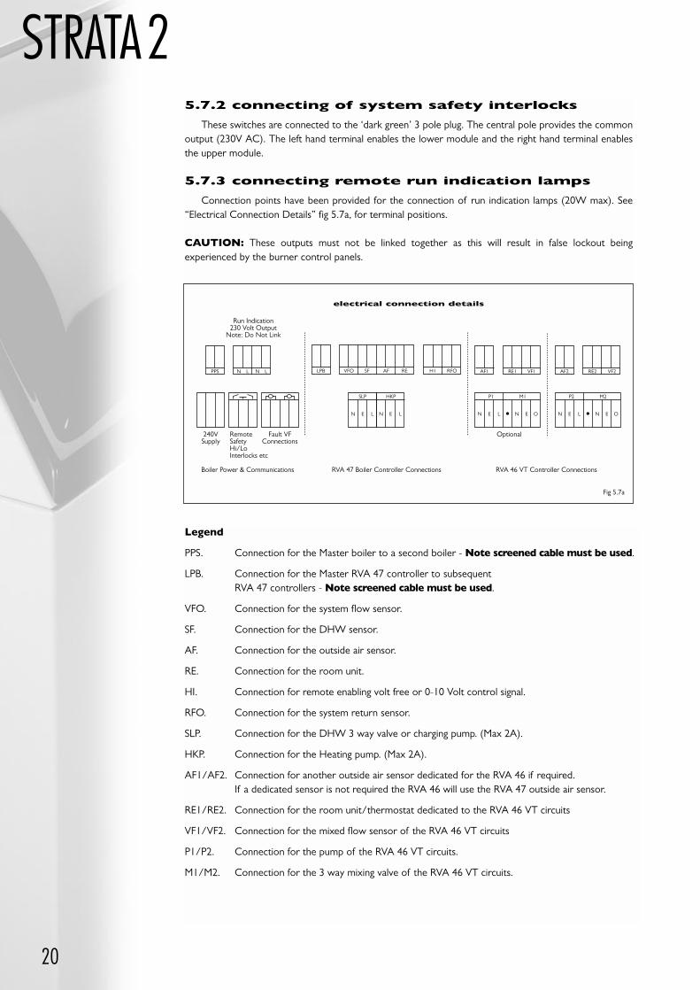
STRATA25.7.2 connecting of system safety interlocks
These switches are connected to the ‘dark green’ 3 pole plug. The central pole provides the commonoutput (230V AC). The left hand terminal enables the lower module and the right hand terminal enablesthe upper module.
5.7.3 connecting remote run indication lamps
Connection points have been provided for the connection of run indication lamps (20W max). See“Electrical Connection Details” fig 5.7a, for terminal positions.
CAUTION: These outputs must not be linked together as this will result in false lockout beingexperienced by the burner control panels.
Legend
PPS. Connection for the Master boiler to a second boiler - Note screened cable must be used.
LPB. Connection for the Master RVA 47 controller to subsequent RVA 47 controllers - Note screened cable must be used.
VFO. Connection for the system flow sensor.
SF. Connection for the DHW sensor.
AF. Connection for the outside air sensor.
RE. Connection for the room unit.
HI. Connection for remote enabling volt free or 0-10 Volt control signal.
RFO. Connection for the system return sensor.
SLP. Connection for the DHW 3 way valve or charging pump. (Max 2A).
HKP. Connection for the Heating pump. (Max 2A).
AF1/AF2. Connection for another outside air sensor dedicated for the RVA 46 if required.If a dedicated sensor is not required the RVA 46 will use the RVA 47 outside air sensor.
RE1/RE2. Connection for the room unit/thermostat dedicated to the RVA 46 VT circuits
VF1/VF2. Connection for the mixed flow sensor of the RVA 46 VT circuits
P1/P2. Connection for the pump of the RVA 46 VT circuits.
M1/M2. Connection for the 3 way mixing valve of the RVA 46 VT circuits.
PPS N L N L AF1 RE1 VF1 AF2 RE2 VF2LPB VFO SF AF RE H1 RFO
SLP
N E L N E L N E O
HKP P1 M1
N E L N E L N E O
P2 M2
electrical connection details
Run Indication230 Volt Output
Note: Do Not Link
240VSupply
Fault VFConnections
OptionalRemoteSafetyHi/LoInterlocks etc
Boiler Power & Communications RVA 47 Boiler Controller Connections RVA 46 VT Controller Connections
Fig 5.7a
21
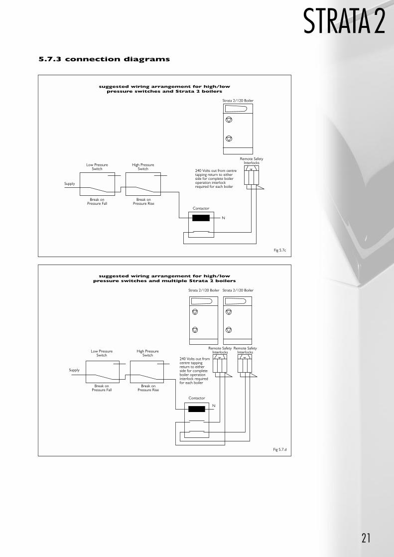
STRATA2
suggested wiring arrangement for high/lowpressure switches and Strata 2 boilers
Strata 2/120 Boiler
Low PressureSwitch
Break onPressure Fall
Break onPressure Rise
High PressureSwitch
Supply
Remote SafetyInterlocks
240 Volts out from centretapping return to eitherside for complete boileroperation interlockrequired for each boiler
Contactor
N
suggested wiring arrangement for high/lowpressure switches and multiple Strata 2 boilers
Strata 2/120 BoilerStrata 2/120 Boiler
Low PressureSwitch
Break onPressure Fall
Break onPressure Rise
High PressureSwitch
Supply
Remote SafetyInterlocks
Remote SafetyInterlocks
240 Volts out fromcentre tappingreturn to eitherside for completeboiler operationinterlock requiredfor each boiler
Contactor
N
5.7.3 connection diagrams
Fig 5.7c
Fig 5.7.d
22
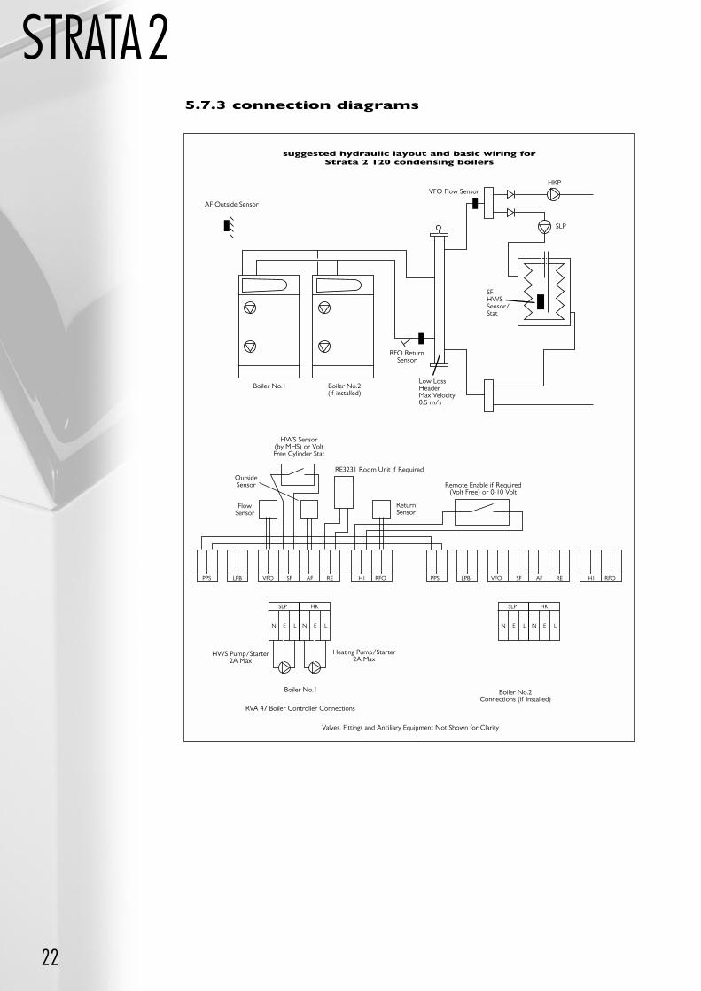
STRATA2
suggested hydraulic layout and basic wiring forStrata 2 120 condensing boilers
AF Outside Sensor
Boiler No.1 Boiler No.2(if installed)
RFO ReturnSensor
HKP
SLP
VFO Flow Sensor
SFHWSSensor/Stat
Low LossHeaderMax Velocity0.5 m/s
PPS
SLP
N E L
LPB VFO SF AF RE H1 RFO PPS LPB VFO SF AF RE H1 RFO
HK
N E L
SLP
N E L
HK
N E L
HWS Sensor (by MHS) or VoltFree Cylinder Stat
HWS Pump/Starter2A Max
Heating Pump/Starter2A Max
Boiler No.1
RVA 47 Boiler Controller Connections
RE3231 Room Unit if Required
Remote Enable if Required(Volt Free) or 0-10 Volt
Boiler No.2Connections (if Installed)
Valves, Fittings and Anciliary Equipment Not Shown for Clarity
5.7.3 connection diagrams
FlowSensor
ReturnSensor
OutsideSensor
23
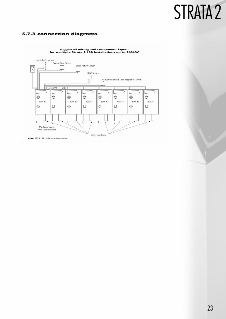
STRATA25.7.3 connection diagrams
suggested wiring and component layoutfor multiple Strata 2 120 installations up to 960kW
Outside Air Sensor
230 Perm SupplyWith Local Isolators
RVA 47 RVA 47 RVA 47 RVA 47 RVA 47 RVA 47 RVA 47
H1 Remote Enable (Volt Fee)/or 0-10 volt
PPS
HWS Sensor
System Flow SensorBoiler Return Sensor
LPB
Safety Interlocks
Note: PPS & LPB cables must be screened
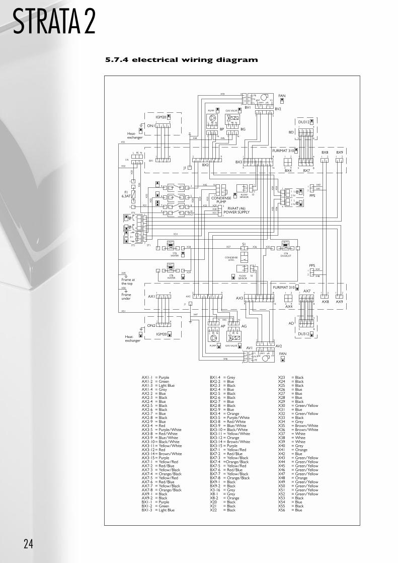
5.7.4 electrical wiring diagram
24
STRATA2
PUMP GAS VALVE
X43 3
1
PE
N
Lgnd
pwm plsV+
1 5
BV1 BV2
FAN
BP BG
L PE N L PE N
1 N 1 NX44 X45
BD
FURIMAT 310
DU3121 4
5 8
1 4
5 8
BX8 BX91 21 2
3 4
1 2
BX4
1921
1
4
6
7
9
3
5 1
8
10X27
2
4
1 4
BX1LN
X52
X32
X21
X20
X26
X33
X25
X28 X
24
X23
L PE N
8
9 16
BX3BX2
CONDENSEPUMP
RVA47 (46)POWER SUPPLY
J1BX7
PPS
ON1
IGM20
Heat-exchanger
F16,3AT
X22
X42
FLOWSENSOR
N 1
2S3
X29
X30
X31
3
1
X54
X53
X55
X56
1
4
1
2
L
N
1
2
L
N
1
2
X40
X41
1
4
1
3
ST3
ST2 ST17
1
X24
M-T
X38
STBWATER
M-T
X39STB
WATER
X37 X36 X35
CONDENSELEVEL
FLOWSENSOR
1
2
S2
S1
PPS
M-T
STBEXHAUST
X34
X48
1
2
Frame atthe top
Frameunder AX1
X49
X50
X51
1 4 2 9 1 8 1 2 1 2 1 21 4
5 8
1 4
5 8
3 49 16
AX2
J1
AX3
AX4
AD
AX7
AX8 AX9
FURIMAT 310
DU312
PUMP GAS VALVE
X46
3
1
PE
N
Lgnd
pwm plsV+
1 5
AV1 AV2
FAN
AP AG
L PE N L PE N
1 N 1 N
X47
X451 4
ON2
IGM20Heat-exchanger
AX1-1 = PurpleAX1-2 = GreenAX1-3 = Light BlueAX1-4 = GreyAX2-2 = BlueAX2-3 = BlackAX2-4 = BlueAX2-5 = BlackAX2-6 = BlackAX2-7 = BlueAX2-8 = BlackAX2-9 = BlueAX3-4 = RedAX3-5 = Purple/WhiteAX3-8 = Red/WhiteAX3-9 = Blue/WhiteAX3-10= Black/WhiteAX3-11= Yellow/WhiteAX3-12= RedAX3-14= Brown/WhiteAX3-15= PurpleAX7-1 = Yellow/RedAX7-2 = Red/BlueAX7-3 = Yellow/BlackAX7-4 = Orange/BlackAX7-5 = Yellow/RedAX7-6 = Red/BlueAX7-7 = Yellow/BlackAX7-8 = Orange/BlackAX9-1 = BlackAX9-2 = BlackBX1-1 = PurpleBX1-2 = GreenBX1-3 = Light Blue
BX1-4 = GreyBX2-2 = BlueBX2-3 = BlackBX2-4 = BlueBX2-5 = BlackBX2-6 = BlackBX2-7 = BlueBX2-8 = BlackBX2-9 = BlueBX3-4 = OrangeBX3-5 = Purple/WhiteBX3-8 = Red/WhiteBX3-9 = Blue/WhiteBX3-10 = Black/WhiteBX3-11 = Yellow/WhiteBX3-12 = OrangeBX3-14 = Brown/WhiteBX3-15 = PurpleBX7-1 = Yellow/RedBX7-2 = Red/BlueBX7-3 = Yellow/BlackBX7-4 =Orange/BlackBX7-5 = Yellow/RedBX7-6 = Red/BlueBX7-7 = Yellow/BlackBX7-8 = Orange/BlackBX9-1 = BlackBX9-2 = BlackX3-16 = GreyX8-1 = GreyX8-2 = OrangeX20 = BlackX21 = BlackX22 = Black
X23 = BlackX24 = BlackX25 = BlackX26 = BlueX27 = BlueX28 = BlueX29 = BlackX30 = Green/YellowX31 = BlueX32 = Green/YellowX33 = BlackX34 = GreyX35 = Brown/WhiteX36 = Brown/WhiteX37 = WhiteX38 = WhiteX39 = WhiteX40 = GreyX41 = OrangeX42 = BlueX43 = Green/YellowX44 = Green/YellowX45 = Green/YellowX46 = Green/YellowX47 = Green/YellowX48 = OrangeX49 = Green/YellowX50 = Green/YellowX51 = Green/YellowX52 = Green/YellowX53 = BlackX54 = BlueX55 = BlackX56 = Blue
25
STRATA2
Table 5
5.7.5 connecting remote fault alarms
The boiler includes a normally open volt free contact for each module, which closes in the event of alockout failure. See “Electrical Connection Details” section 5.7.
5.8 connecting additional boilers
A second boiler unit does not require an additional RVA 47 manager, as the manager in the first unit iscapable of controlling up to 4 burners. Connect the power supply to the second unit. Install a pair ofscreened wires between the PPS connectors of boilers 1 and 2. Observe polarity.
Note: PPS connector = light blue.
5.8.1 connecting third, fourth, fifth, sixth,seventh and eighth units
These boilers must have RVA 47 managers. To connect RVA 47 manager in additional boilers; the LPBterminals in each boiler that includes an RVA 47 manager must be linked, i.e. all left hand LPB terminals mustbe linked on to another, and all right hand LPB terminals must be linked one to another. Do not link any lefthand terminal to any right hand terminal. Screened cables required.
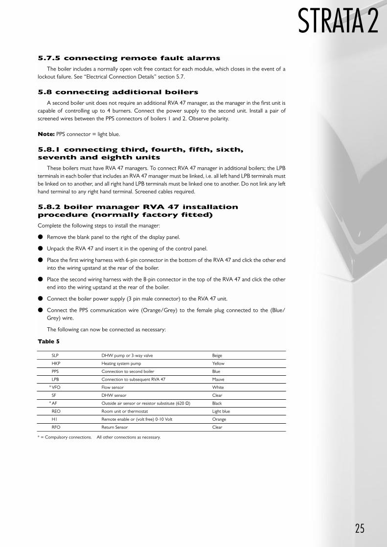
5.8.2 boiler manager RVA 47 installationprocedure (normally factory fitted)
Complete the following steps to install the manager:
Remove the blank panel to the right of the display panel.
Unpack the RVA 47 and insert it in the opening of the control panel.
Place the first wiring harness with 6-pin connector in the bottom of the RVA 47 and click the other endinto the wiring upstand at the rear of the boiler.
Place the second wiring harness with the 8-pin connector in the top of the RVA 47 and click the otherend into the wiring upstand at the rear of the boiler.
Connect the boiler power supply (3 pin male connector) to the RVA 47 unit.
Connect the PPS communication wire (Orange/Grey) to the female plug connected to the (Blue/Grey) wire.
The following can now be connected as necessary:
SLP DHW pump or 3-way valve Beige
HKP Heating system pump Yellow
PPS Connection to second boiler Blue
LPB Connection to subsequent RVA 47 Mauve
VFO Flow sensor White
SF DHW sensor Clear
AF Outside air sensor or resistor substitute (620 Ω) Black
REO Room unit or thermostat Light blue
H1 Remote enable or (volt free) 0-10 Volt Orange
RFO Return Sensor Clear
* = Compulsory connections. All other connections as necessary.
*
*
26
STRATA2
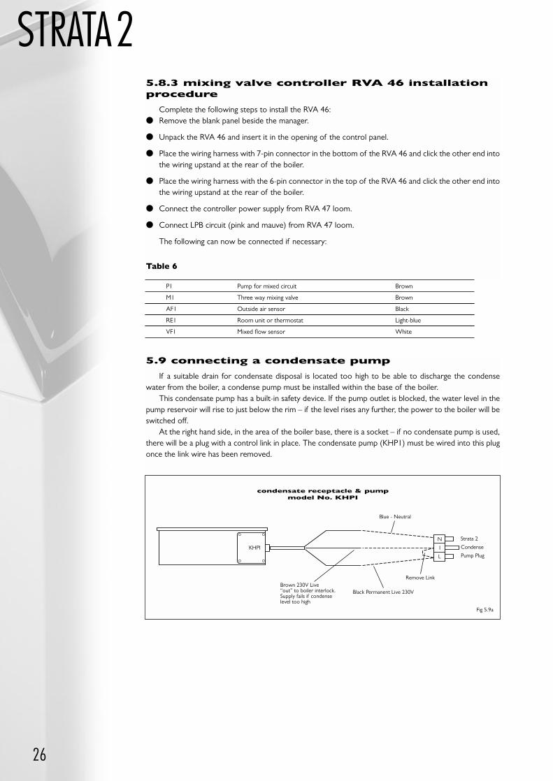
5.9 connecting a condensate pump
If a suitable drain for condensate disposal is located too high to be able to discharge the condensewater from the boiler, a condense pump must be installed within the base of the boiler.
This condensate pump has a built-in safety device. If the pump outlet is blocked, the water level in thepump reservoir will rise to just below the rim – if the level rises any further, the power to the boiler will beswitched off.
At the right hand side, in the area of the boiler base, there is a socket – if no condensate pump is used,there will be a plug with a control link in place. The condensate pump (KHP1) must be wired into this plugonce the link wire has been removed.
condensate receptacle & pumpmodel No. KHPI
KHPI
Blue - Neutral
Brown 230V Live“out” to boiler interlock.Supply fails if condenselevel too high
Black Permanent Live 230V
Remove Link
Strata 2
Condense
Pump Plug
N
I
L
Fig 5.9a
5.8.3 mixing valve controller RVA 46 installationprocedure
Complete the following steps to install the RVA 46: Remove the blank panel beside the manager.
Unpack the RVA 46 and insert it in the opening of the control panel.
Place the wiring harness with 7-pin connector in the bottom of the RVA 46 and click the other end intothe wiring upstand at the rear of the boiler.
Place the wiring harness with the 6-pin connector in the top of the RVA 46 and click the other end intothe wiring upstand at the rear of the boiler.
Connect the controller power supply from RVA 47 loom.
Connect LPB circuit (pink and mauve) from RVA 47 loom.
The following can now be connected if necessary:
P1 Pump for mixed circuit Brown
M1 Three way mixing valve Brown
AF1 Outside air sensor Black
RE1 Room unit or thermostat Light-blue
VF1 Mixed flow sensor White
Table 6
27
STRATA2
The Strata 2-120 should be commissioned by a competent engineer. Before commissioning theappliance, the whole gas installation including the meter MUST be purged and tested for gas soundness inaccordance with BS6891:1988.
CAUTION: Open all doors and windows, extinguish naked lights and DO NOT SMOKE whilst purgingthe gas line.
The entire system must be thoroughly cleansed and flushed to remove debris, flux residues etc beforeopening the boiler isolation valves and flooding the boiler. Particular care must be taken where theappliance is being retro-fitted into and old/existing system, as system silt or magenite can be very damagingto the new boiler.
Following cleansing and flushing the system must be dosed with a good qualitywater treatment to prevent corrosion and the formation of scale. Failure to observethese requirements will render the guarantee on the product void.
Cleansing, flushing and water treatment must be carried out in accordance withthe requirements of BS7593:1992.
The return pipework must include some method of filtering or straining. The filter or strainer must befitted with isolation valves to allow easy cleaning with the minimum amount of water loss and waterreplenishment.
A low water pressure switch must be included within the system design and interlocked to the boilerto shut the boiler down in the event of the water pressure falling below 0.5 bar.
Note: The Strata 2 boiler has heat exchangers fabricated from 316L stainless steel.It is most important that the compatibility of any flux is checked with the fluxsupplier before use, and that any flux manufacturers recommendations are strictlyfollowed with regards to use in conjunction with stainless steel.
6.1 Filling the Boiler
The Strata 2-120 and the central heating installation must be filled by a competent person using one ofthe approved methods in BS 6644:1991 and using the filling/draining cock in the installation.
The unit has a manometer, which indicates the filling pressure. Fill the installation and vent the boiler.Continue to fill the installation until the correct central heating water pressure has been reached.
Minimum static head – 5m.
6.0 commissioning
and testing
5.9.1 Condensate Receptacle and Pump – Model No. KHP1
The KHP1 condensate pump is designed to collect and pump away condensate water produced bycondensing boilers and is particularly suitable for use with the Strata 2.
The KHP1 may be installed directly inside the base area of the Strata 2 making a concealed installation.The receptacle includes a permanently wet sump area where pH adjustment granules may be dosed toneutralise the pH of the condensate water.
technical data
Pump Transfer Height 5m
Transfer Volume/cycle 2 litres (approx)
Transfer Time/cycle 17 seconds (approx)
Power Supply 230V 50Hz
Pump 12V dc
Pump Outlet 10mm OD Male Spigot
Capacity pH Granules 7kg
Dimensions 465W x 380D x 120H
Supply Cable Length 1.8m
10mm Discharge Hose Length 5m
Condense Inlet open aperture in unit top
28
STRATA2
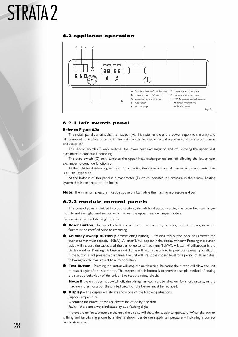
6.2.1 left switch panel
Refer to Figure 6.2aThe switch panel contains the main switch (A), this switches the entire power supply to the unity and
all connected controllers on and off. The main switch also disconnects the power to all connected pumpsand valves etc.
The second switch (B) only switches the lower heat exchanger on and off, allowing the upper heatexchanger to continue functioning.
The third switch (C) only switches the upper heat exchanger on and off allowing the lower heatexchanger to continue functioning.
At the right hand side is a glass fuse (D) protecting the entire unit and all connected components. Thisis a 6.3AT type fuse.
At the bottom of this panel is a manometer (E) which indicates the pressure in the central heatingsystem that is connected to the boiler.
Note: The minimum pressure must be above 0.5 bar, while the maximum pressure is 4 bar.
6.2.2 module control panels
This control panel is divided into two sections, the left hand section serving the lower heat exchangermodule and the right hand section which serves the upper heat exchanger module.
Each section has the following controls:
Reset Button – In case of a fault, the unit can be restarted by pressing this button. In general thefault must be rectified prior to restarting.
Chimney Sweep Button (Commissioning button) – Pressing this button once will activate theburner at minimum capacity (10kW). A letter ‘L’ will appear in the display window. Pressing this buttontwice will increase the capacity of the burner up to its maximum (60kW). A letter ‘H’ will appear in thedisplay window. Pressing this button a third time will return the unit to its previous operating condition.If the button is not pressed a third time, the unit will fire at the chosen level for a period of 10 minutes,following which it will revert to auto operation.
Test Button – Pressing this button will stop the unit burning. Releasing the button will allow the unitto restart again after a short time. The purpose of this button is to provide a simple method of testingthe start-up behaviour of the unit and to test the safety circuit.
Note: If the unit does not switch off, the wiring harness must be checked for short circuits, or themaximum thermostat or the printed circuit of the burner must be replaced.
Display – The display will always show one of the following situations.Supply TemperatureOperating messages:- these are always indicated by one digitFaults:- these are always indicated by two flashing digits
If there are no faults present in the unit, the display will show the supply temperature. When the burneris firing and functioning properly, a ‘dot’ is shown beside the supply temperature – indicating a correctrectification signal.
0
12
3
4
A B C D H I I
E F G
A Double pole on/off switch (main)
B Lower burner on/off switch
C Upper burner on/off switch
D Fuse holder
E Altitude gauge
F Lower burner status panel
G Upper burner status panel
H RVA 47 cascade control manager
I Knockout for additionaloptional controls
Fig 6.2a
6.2 appliance operation
29
STRATA2
Table 8DIP Switches 1-4
If the unit is converted to liquid gas, DIP switch 8 must be set to ON; this automatically lowers themaximum speed of the combustion fan, to obtain the required capacity.
If the unit is fitted with Grundfos Pumps DIP switch 5 should be switched on, to allow the pumps tomodulate. If modulation is not required DIP switch 5 should be switched off.
If the RAV 47 has malfunctioned, DIP switch 6 may be switched to ON, as an emergency measure, afterwhich the unit will be kept at a steady 70ºC, independent of the heat demand. When the replacementcontroller has been installed, DIP switch 6 must be set to OFF again.
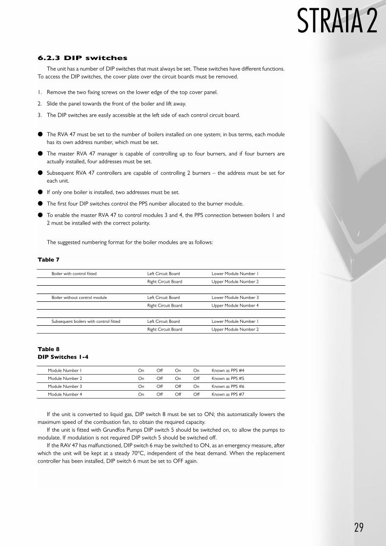
6.2.3 DIP switches
The unit has a number of DIP switches that must always be set. These switches have different functions.To access the DIP switches, the cover plate over the circuit boards must be removed.
1. Remove the two fixing screws on the lower edge of the top cover panel.
2. Slide the panel towards the front of the boiler and lift away.
3. The DIP switches are easily accessible at the left side of each control circuit board.
The RVA 47 must be set to the number of boilers installed on one system; in bus terms, each modulehas its own address number, which must be set.
The master RVA 47 manager is capable of controlling up to four burners, and if four burners areactually installed, four addresses must be set.
Subsequent RVA 47 controllers are capable of controlling 2 burners – the address must be set for each unit.
If only one boiler is installed, two addresses must be set.
The first four DIP switches control the PPS number allocated to the burner module.
To enable the master RVA 47 to control modules 3 and 4, the PPS connection between boilers 1 and2 must be installed with the correct polarity.
The suggested numbering format for the boiler modules are as follows:
Boiler with control fitted Left Circuit Board Lower Module Number 1
Right Circuit Board Upper Module Number 2
Boiler without control module Left Circuit Board Lower Module Number 3
Right Circuit Board Upper Module Number 4
Subsequent boilers with control fitted Left Circuit Board Lower Module Number 1
Right Circuit Board Upper Module Number 2
Table 7
Module Number 1 On Off On On Known as PPS #4
Module Number 2 On Off On Off Known as PPS #5
Module Number 3 On Off Off On Known as PPS #6
Module Number 4 On Off Off Off Known as PPS #7
30
STRATA26.3 firing the appliance
At the time of starting the appliance, the working gas pressure must be measured:
The inlet working gas pressure must be measured at the inlet test nipple of the gas control valve. (see fig 6.4a).
Nominal pressure should be 20 mbar for the Natural gas and 37 mbar for LPG (Propane).
6.3.1 initial start up
Ensuring that the installation has been fully tested and having found everything in order, power can beapplied to the unit by switching the main switch (fig 6.2a) to the ON position. Now place the switch forthe lower module in the ON position. To be independent from the heat demand from the installation, pressthe ‘Chimney Sweep’ button ONCE. The lower burner should ignite. If the appliance fails to start up, firstcheck whether all gas taps, including the one on the unit have been opened.
Electrically, there is fourfold start-up procedure, after which a fault is reported (by flashing warning onthe status display); press the RESET button for additional start up attempts. If the unit fails to start upcorrectly, the adjustment screw (2) (see fig 6.4a) on the gas valve must be turned clockwise 1/4 turn, andthen attempt to restart the appliance.
Note: If the display fails to show a figure, the RESET button should be pressed.
The start-up cycle has the following stages:
The combustion fan carries out an initial speed test at low speed – after which it will immediately switch to:
Start Speed; when this has been reached, the gas valve will open and the unit will start up at 50% of itscapacity.
The safety time is 5 seconds, after which there is a stabilisation period for the flames, also lasting 5seconds; this is followed by the units output being controlled via the RVA 47 cascade manager.
6.4 setting and adjusting the load
For checking purposes, or after installing a new gas control valve, there are two methods for setting thecorrect load.
By measuring the CO2 percentage.
Checking by means of the gas rate measuring method.
Emissions must be measured in the opening, in the upper front right of the heat exchanger module, byfirst removing the test point cap. Refit test point cap when emissions checks have been completed.
Table 9Unit Settings
For Natural Gas G20Gas measuring method:
Maximum load per Heat Exchanger – 213ft3/hour.
Minimum load per Heat Exchanger – 42.6ft3/hour.
Note: Values measured at a boiler water temperature of circa 60ºC.
Type of Gas Natural Gas G20 Propane Gas
Wobbe (MJ/m3) 49.79 76.06
Calorific Value Gross (MJ/m3) 38.63 93.87
CO2 Max Load (%) 9 11
CO2 Min Load (%) 9.5 11.5
31
STRATA2
3
2
1
gas valve
Q max
Q min
Burner offsetpressuretest point
Adjustments
Turning 2 clockwise increases min output & CO2 %Turning 3 Anti clockwise increases max output & CO2 %
6.4.2 setting maximum load
The correct CO2 combustion on low fire should now have been achieved. To set the maximum load:
Press the ‘Chimney Sweep’ button a second time, the letter ‘H’ will appear in the display and the unitwill begin to operate at maximum capacity.
Again check the combustion figures.
If the CO2 content is below the stated figure, increase the gas throughput by turning the adjusting screw(3) counter-clockwise.
If the CO2 content is above the stated figure decrease the gas throughput by turning the adjusting screw(3) clockwise.
Pressing the ‘Chimney Sweep’ button a third time will return the unit to automatic mode, and thedisplay will show the flow temperature.
Note: Adjusting the high fire, has a marked effect on the low fire figures, whereas adjusting the low firehas little effect on the high fire figures.
It is therefore suggested that once the initial set-up has been carried out, a check is made of the twosettings before returning the unit to complete automatic operation.
6.4.3 setting maximum/minimum load for upper module
Repeat operations described in 6.4.1 and 6.4.2 – but applied to the upper module.
6.5 setting for propane gas
To set the unit for propane gas, complete the following steps:
Disassemble the gas pipe between the gas valve and the gas air pipe.
Install a propane nozzle with a diameter of 7mm on the outlet of the gas valve.
Reconnect the gas pipe.
To obtain the correct capacity, the combustion fan speed must be adapted for propane gas, by placingthe DIP switch 8 in the ON position.
Fig 6.4a
6.4.1 settingminimum load
To set the minimum load refer to figure 6.4a andfollow the instructions below:
Press the ‘Chimney Sweep’ button once, theletter ‘L’ will appear in the display and the unitwill commence operation at minimum capacity,for up to 10 minutes.
Check the combustion figures with thosestated above.
If the CO2 content is below the stated figure,increase the gas throughput by turning theadjusting screw (2) clockwise.
If the CO2 content is above the stated figure,decrease the gas throughput by turning theadjusting screw (2) counter-clockwise.
32
STRATA26.6 setting domestic hot water
The RVA 47 cascade manager can be set to control the temperature of the DHW either by means ofa dedicated sensor or thermostat.
6.7 switching off the appliance
It is recommended to leave the appliance running throughout the year in order to prevent the unit fromfreezing, or moving parts from becoming blocked by corrosion. In order to avoid this, set the RVA 47controller to the ‘standby’ position.
In this mode, the central heating unit will run the attached pumps for 1 minute in every 24 hours, whilethe frost protection may remain operative.
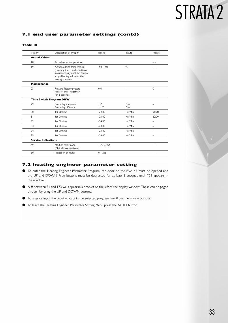
Table 10
(Prog#) Description of Prog # Range Inputs Preset
Time of Day
1 Time of day 0-23:59 Hr/Min 00:00
2 Weekday 1…7 Day 1
Time Switch Program Heating
5 Every day the same 1-7 Day –Every day different 1…7 Day
6 1st On time -24:00 Hr/Min 06:00
7 1st On time -24:00 Hr/Min 22:00
8 2nd On time -24:00 Hr/Min –
9 2nd On time -24:00 Hr/Min –
10 3rd On time -24:00 Hr/Min –
11 3rd On time -24:00 Hr/Min –
Hot Water Service
13 Required DHW temperature 40-60 ºC 55
Heating Circuit
14 Night set back temperature 10-30 ºC 16
15 Frost protection temperature 4-15 ºC 10
16 Summer/winter switching 8-30 ºC 17
17 Slope of heating curve -/2.5.40 ºC 32
7.0 boiler
control settingsConsult the descriptions provided with the various Seimens (Landis Steafa) control units, for full
instructions on application and usage. In the absence of full control instructions the following abridgedinstructions will be useful.
7.1 end user parameter settings
To enter the End User Parameter Program, the door on the RVA 47 must be opened and one of theUP or DOWN prog buttons must be depressed.
A number between 1 and 50 will appear in a bracket on the left of the display window. These can bepaged through by using the UP or DOWN buttons.
To alter or input the required data in the selected program line # use the + or – buttons.
To leave the End User Parameter Setting Menu press the AUTO button.
The defaults indicated below are for standard systems. If additional control features are requiredalteration will have to be made. Please refer to the RVA 47 manual for additional details.
#, –, – – – Indicates where an input can be made if required.
– – Indicates where an input cannot be made and a sensed/attenuated figure is displayed. ‘OFF’ will be displayed if the +/- buttons are used.
33
STRATA2
7.2 heating engineer parameter setting
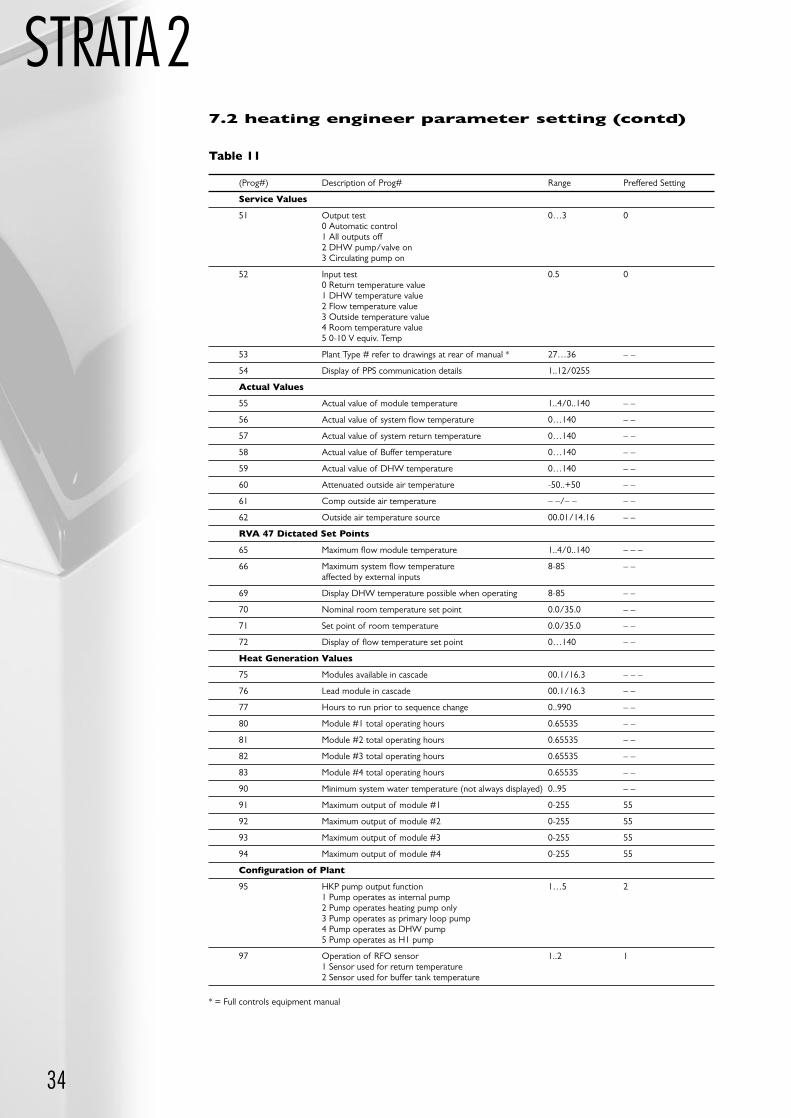
To enter the Heating Engineer Parameter Program, the door on the RVA 47 must be opened and the UP and DOWN Prog buttons must be depressed for at least 3 seconds until #51 appears in the window.
A # between 51 and 173 will appear in a bracket on the left of the display window. These can be pagedthrough by using the UP and DOWN buttons.
To alter or input the required data in the selected program line # use the + or – buttons.
To leave the Heating Engineer Parameter Setting Menu press the AUTO button.
Table 10
7.1 end user parameter settings (contd)
(Prog#) Description of Prog # Range Inputs Preset
Actual Values
18 Actual room temperature – –
19 Actual outside temperature -50. +50 ºC – –(Pressing the + and – buttons simultaneously until the display stops flashing will reset the averaged value)
Maintenance
23 Restore factory presets 0/1 – 0Press + and – together for 3 seconds
Time Switch Program DHW
29 Every day the same 1-7 Day –Every day different 1…7 Day
30 1st Ontime -24:00 Hr/Min 06:00
31 1st Ontime -24:00 Hr/Min 22:00
32 1st Ontime -24:00 Hr/Min –
33 1st Ontime -24:00 Hr/Min –
34 1st Ontime -24:00 Hr/Min –
35 1st Ontime -24:00 Hr/Min –
Service Indications
49 Module error code 1..4/0..255 – –(Not always displayed)
50 Indication of faults 0…255 – –
34
STRATA2
(Prog#) Description of Prog# Range Preffered Setting
Service Values
51 Output test 0…3 00 Automatic control1 All outputs off2 DHW pump/valve on3 Circulating pump on
52 Input test 0.5 00 Return temperature value1 DHW temperature value2 Flow temperature value3 Outside temperature value4 Room temperature value5 0-10 V equiv. Temp
53 Plant Type # refer to drawings at rear of manual * 27…36 – –
54 Display of PPS communication details 1..12/0255
Actual Values
55 Actual value of module temperature 1..4/0..140 – –
56 Actual value of system flow temperature 0…140 – –
57 Actual value of system return temperature 0…140 – –
58 Actual value of Buffer temperature 0…140 – –
59 Actual value of DHW temperature 0…140 – –
60 Attenuated outside air temperature -50..+50 – –
61 Comp outside air temperature – –/– – – –
62 Outside air temperature source 00.01/14.16 – –
RVA 47 Dictated Set Points
65 Maximum flow module temperature 1..4/0..140 – – –
66 Maximum system flow temperature 8-85 – –affected by external inputs
69 Display DHW temperature possible when operating 8-85 – –
70 Nominal room temperature set point 0.0/35.0 – –
71 Set point of room temperature 0.0/35.0 – –
72 Display of flow temperature set point 0…140 – –
Heat Generation Values
75 Modules available in cascade 00.1/16.3 – – –
76 Lead module in cascade 00.1/16.3 – –
77 Hours to run prior to sequence change 0..990 – –
80 Module #1 total operating hours 0.65535 – –
81 Module #2 total operating hours 0.65535 – –
82 Module #3 total operating hours 0.65535 – –
83 Module #4 total operating hours 0.65535 – –
90 Minimum system water temperature (not always displayed) 0..95 – –
91 Maximum output of module #1 0-255 55
92 Maximum output of module #2 0-255 55
93 Maximum output of module #3 0-255 55
94 Maximum output of module #4 0-255 55
Configuration of Plant
95 HKP pump output function 1…5 21 Pump operates as internal pump2 Pump operates heating pump only3 Pump operates as primary loop pump4 Pump operates as DHW pump5 Pump operates as H1 pump
97 Operation of RFO sensor 1..2 11 Sensor used for return temperature2 Sensor used for buffer tank temperature
Table 11
7.2 heating engineer parameter setting (contd)
* = Full controls equipment manual
35
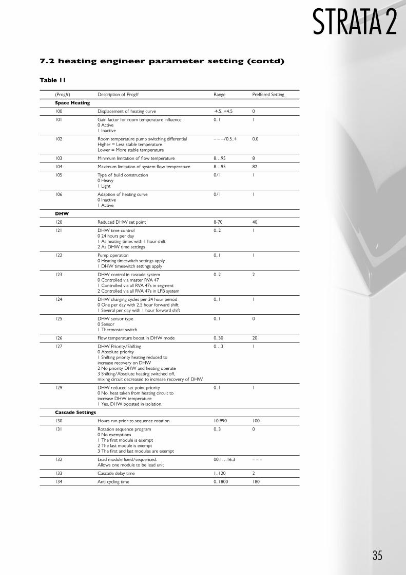
STRATA2Table 11
7.2 heating engineer parameter setting (contd)
(Prog#) Description of Prog# Range Preffered Setting
Space Heating
100 Displacement of heating curve -4.5..+4.5 0
101 Gain factor for room temperature influence 0..1 10 Active1 Inactive
102 Room temperature pump switching differential – – –/0.5..4 0.0Higher = Less stable temperatureLower = More stable temperature
103 Minimum limitation of flow temperature 8…95 8
104 Maximum limitation of system flow temperature 8…95 82
105 Type of build construction 0/1 10 Heavy1 Light
106 Adaption of heating curve 0/1 10 Inactive1 Active
DHW
120 Reduced DHW set point 8-70 40
121 DHW time control 0..2 10 24 hours per day1 As heating times with 1 hour shift2 As DHW time settings
122 Pump operation 0..1 10 Heating timeswitch settings apply1 DHW timeswitch settings apply
123 DHW control in cascade system 0..2 20 Controlled via master RVA 471 Controlled via all RVA 47s in segment2 Controlled via all RVA 47s in LPB system
124 DHW charging cycles per 24 hour period 0..1 10 One per day with 2.5 hour forward shift1 Several per day with 1 hour forward shift
125 DHW sensor type 0..1 00 Sensor1 Thermostat switch
126 Flow temperature boost in DHW mode 0..30 20
127 DHW Priority/Shifting 0…3 10 Absolute priority1 Shifting priority heating reduced to increase recovery on DHW2 No priority DHW and heating operate3 Shifting/Absolute heating switched off, mixing circuit decreased to increase recovery of DHW.
129 DHW reduced set point priority 0..1 10 No, heat taken from heating circuit to increase DHW temperature1 Yes, DHW boosted in isolation.
Cascade Settings
130 Hours run prior to sequence rotation 10.990 100
131 Rotation sequence program 0..3 00 No exemptions1 The first module is exempt2 The last module is exempt3 The first and last modules are exempt
132 Lead module fixed/sequenced. 00.1…16.3 – – –Allows one module to be lead unit
133 Cascade delay time 1..120 2
134 Anti cycling time 0..1800 180
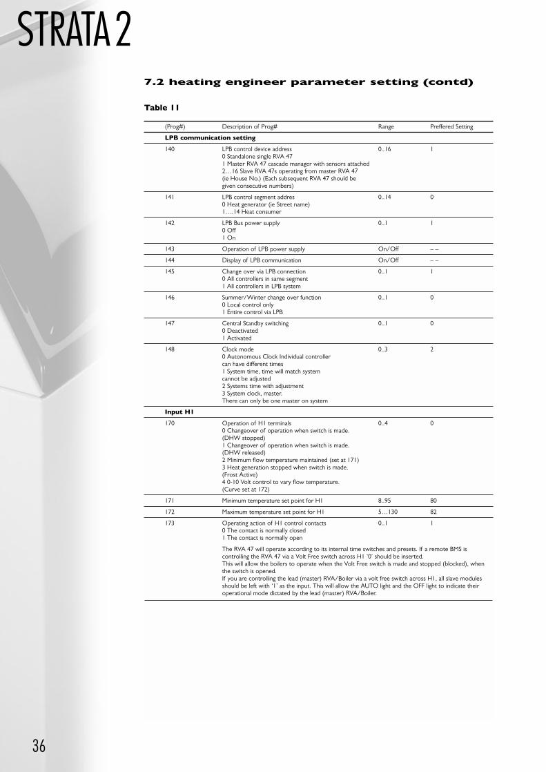
36
STRATA2
(Prog#) Description of Prog# Range Preffered Setting
LPB communication setting
140 LPB control device address 0..16 10 Standalone single RVA 471 Master RVA 47 cascade manager with sensors attached2…16 Slave RVA 47s operating from master RVA 47 (ie House No.) (Each subsequent RVA 47 should be given consecutive numbers)
141 LPB control segment addres 0..14 00 Heat generator (ie Street name)1….14 Heat consumer
142 LPB Bus power supply 0..1 10 Off1 On
143 Operation of LPB power supply On/Off – –
144 Display of LPB communication On/Off – –
145 Change over via LPB connection 0..1 10 All controllers in same segment1 All controllers in LPB system
146 Summer/Winter change over function 0..1 00 Local control only1 Entire control via LPB
147 Central Standby switching 0..1 00 Deactivated1 Activated
148 Clock mode 0..3 20 Autonomous Clock Individual controller can have different times1 System time, time will match system cannot be adjusted2 Systems time with adjustment3 System clock, master.There can only be one master on system
Input H1
170 Operation of H1 terminals 0..4 00 Changeover of operation when switch is made.(DHW stopped)1 Changeover of operation when switch is made.(DHW released)2 Minimum flow temperature maintained (set at 171)3 Heat generation stopped when switch is made.(Frost Active)4 0-10 Volt control to vary flow temperature.(Curve set at 172)
171 Minimum temperature set point for H1 8..95 80
172 Maximum temperature set point for H1 5…130 82
173 Operating action of H1 control contacts 0..1 10 The contact is normally closed1 The contact is normally open
The RVA 47 will operate according to its internal time switches and presets. If a remote BMS iscontrolling the RVA 47 via a Volt Free switch across H1 ‘0’ should be inserted.This will allow the boilers to operate when the Volt Free switch is made and stopped (blocked), whenthe switch is opened.If you are controlling the lead (master) RVA/Boiler via a volt free switch across H1, all slave modulesshould be left with ‘1’ as the input. This will allow the AUTO light and the OFF light to indicate theiroperational mode dictated by the lead (master) RVA/Boiler.
Table 11
7.2 heating engineer parameter setting (contd)
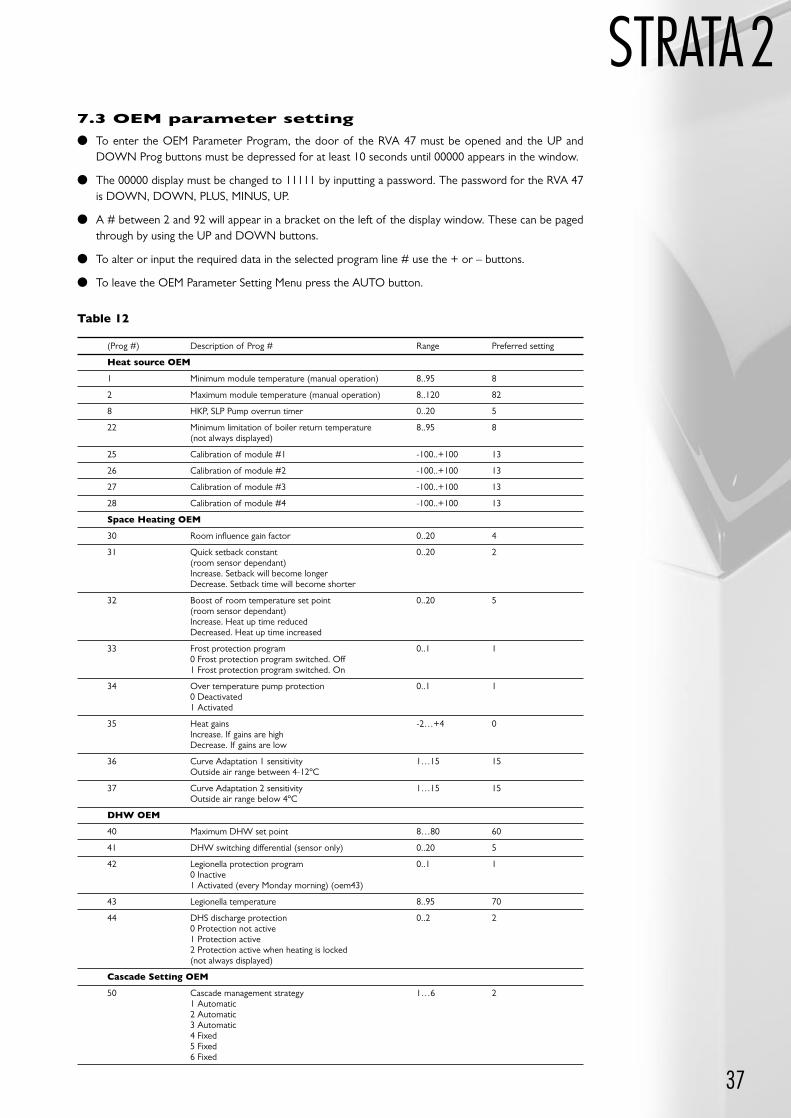
STRATA2
37
Table 12
7.3 OEM parameter setting
To enter the OEM Parameter Program, the door of the RVA 47 must be opened and the UP andDOWN Prog buttons must be depressed for at least 10 seconds until 00000 appears in the window.
The 00000 display must be changed to 11111 by inputting a password. The password for the RVA 47is DOWN, DOWN, PLUS, MINUS, UP.
A # between 2 and 92 will appear in a bracket on the left of the display window. These can be pagedthrough by using the UP and DOWN buttons.
To alter or input the required data in the selected program line # use the + or – buttons.
To leave the OEM Parameter Setting Menu press the AUTO button.
(Prog #) Description of Prog # Range Preferred setting
Heat source OEM
1 Minimum module temperature (manual operation) 8..95 8
2 Maximum module temperature (manual operation) 8..120 82
8 HKP, SLP Pump overrun timer 0..20 5
22 Minimum limitation of boiler return temperature 8..95 8(not always displayed)
25 Calibration of module #1 -100..+100 13
26 Calibration of module #2 -100..+100 13
27 Calibration of module #3 -100..+100 13
28 Calibration of module #4 -100..+100 13
Space Heating OEM
30 Room influence gain factor 0..20 4
31 Quick setback constant 0..20 2(room sensor dependant)Increase. Setback will become longerDecrease. Setback time will become shorter
32 Boost of room temperature set point 0..20 5(room sensor dependant)Increase. Heat up time reducedDecreased. Heat up time increased
33 Frost protection program 0..1 10 Frost protection program switched. Off1 Frost protection program switched. On
34 Over temperature pump protection 0..1 10 Deactivated1 Activated
35 Heat gains -2…+4 0Increase. If gains are highDecrease. If gains are low
36 Curve Adaptation 1 sensitivity 1…15 15Outside air range between 4-12ºC
37 Curve Adaptation 2 sensitivity 1…15 15Outside air range below 4ºC
DHW OEM
40 Maximum DHW set point 8…80 60
41 DHW switching differential (sensor only) 0..20 5
42 Legionella protection program 0..1 10 Inactive1 Activated (every Monday morning) (oem43)
43 Legionella temperature 8..95 70
44 DHS discharge protection 0..2 20 Protection not active1 Protection active2 Protection active when heating is locked (not always displayed)
Cascade Setting OEM
50 Cascade management strategy 1…6 21 Automatic2 Automatic3 Automatic4 Fixed5 Fixed6 Fixed
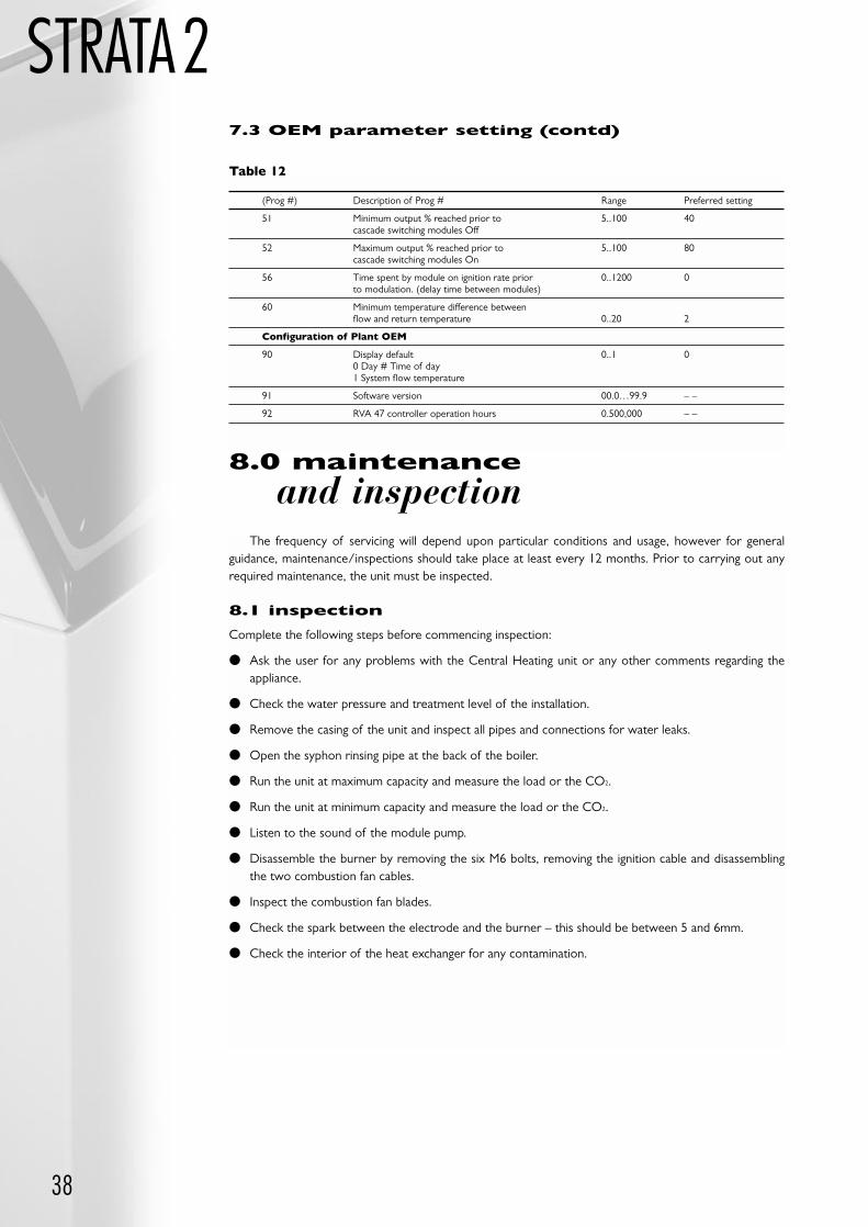
38
STRATA2
(Prog #) Description of Prog # Range Preferred setting
51 Minimum output % reached prior to 5..100 40cascade switching modules Off
52 Maximum output % reached prior to 5..100 80cascade switching modules On
56 Time spent by module on ignition rate prior 0..1200 0to modulation. (delay time between modules)
60 Minimum temperature difference between flow and return temperature 0..20 2
Configuration of Plant OEM
90 Display default 0..1 00 Day # Time of day1 System flow temperature
91 Software version 00.0…99.9 – –
92 RVA 47 controller operation hours 0.500,000 – –
Table 12
7.3 OEM parameter setting (contd)
8.0 maintenance
and inspectionThe frequency of servicing will depend upon particular conditions and usage, however for general
guidance, maintenance/inspections should take place at least every 12 months. Prior to carrying out anyrequired maintenance, the unit must be inspected.
8.1 inspection
Complete the following steps before commencing inspection:
Ask the user for any problems with the Central Heating unit or any other comments regarding theappliance.
Check the water pressure and treatment level of the installation.
Remove the casing of the unit and inspect all pipes and connections for water leaks.
Open the syphon rinsing pipe at the back of the boiler.
Run the unit at maximum capacity and measure the load or the CO2.
Run the unit at minimum capacity and measure the load or the CO2.
Listen to the sound of the module pump.
Disassemble the burner by removing the six M6 bolts, removing the ignition cable and disassemblingthe two combustion fan cables.
Inspect the combustion fan blades.
Check the spark between the electrode and the burner – this should be between 5 and 6mm.
Check the interior of the heat exchanger for any contamination.
STRATA2
39
8.2 maintenance
Any maintenance must be carried out as a result of faults noted in the inspection. Remarks andcomments made by clients must be considered and the causes of any faults or problems must be found.
Note: The pressure of the installation must be not less than 0.5 bar, any leakage within the system willaffect the pressure and so must be identified.
If the module pump makes an un-natural noise, and in particular if the pump is more than 5 years old,the pump should be replaced by way of preventative action.
If the interior of the heat exchanger is contaminated and/or there is a deposit on the stainless steelpipes, the latter must be removed with a hand brush or citric acid (do not use a steel brush). Remove anydirt created with a vacuum cleaner.
Note: Never clean the burner itself.
The Condense syphon must be rinsed. This can be done by removing the burner and using a filling hose,insert water into the heat exchanger, which will automatically reach the syphon.
If dirt has deposited on the combustion fan blades, each blade must be carefully cleaned, until the bladematerial is visible again. If this is not done evenly, the combustion fan will rotate out of balance.
9.1 control panel
The control panel is divided into two sections, the left hand section serves the lower heat exchangerand the right hand section serves the upper heat exchanger.
The two digital displays provide the following information regarding the functioning of the Strata 2-120:
Normal operating situations, the display always shows the flow temperature of the boiler water.
Operating messages, which are always indicated by one digit.
Fault messages, which are always indicated by flashing two digits.
System faults in the FMT 310 module control unit.
9.1.1 operation indicator
An operating message means that the burner of the heat exchanger concerned is not operational, thereason being reported in the operating message. If this situation has resolved itself after some time, the unitwill automatically restart.
0. Unit prevented from operating. Styphon monitoring active.If the water level in the syphon has dropped, the unit will automatically restart.
1. Unit prevented from operating. Water temperature too high, measured by theboiler thermostat. If the water temperature drops by more than 20ºC within 30 seconds, the unit will start to operate,if this is not the case, the unit will lock out.
OR
1. Unit prevented from operating. Condensate syphon overfill.If the condensate produced by the unit is not allowed to pass from the unit to a suitable drain point the level switch located in the base of the flue gas tube will activate and prevent the unit from operating.
9.0 fault
diagnosis
40
STRATA22. Unit prevented from operating. Water temperature too high, measured by the
flow sensor.When the water temperature drops by more than 20ºC the unit will start to operate.
3. Unit prevented from operating. Anti-cycling time.When the anti-cycling time (3 minutes has expired, the unit will automatically fire up again).
5. Unit prevented from operating. Combustion fan speed too high.The combustion fan has been switched off, but a speed indication is still detected. The Strata 1-120will be blocked and after 3 minutes, a locking (flashing) fault will be shown with the same text. If,however, the situation is resolved within 3 minutes, the unit will return to normal operating mode.
7. Unit prevented from operating. Combustion fan speed too low.If this code appears, the Strata 1-120 will be blocked. If the speed has not returned to the normalvalue within 3 minutes, locking will take place. If the situation is resolved within this period, the unitwill resume normal operation.
8. Unit prevented from operating. Flame simulation.Although the burner is not operative, a possible flame is being detected. If this code is shown, theburner control will be blocked. After five seconds, the burner control will be locked.
9. Unit prevented from operating. Limit temperature flue gases.If the flue gas temperature drops by more than 20ºC, the unit will automatically fire up again, if this isnot the case, the unit will lock out.
da Communication between burner control and RVA 27 interrupted (PPS).The burner in question will not operate until the circuit is re-established - check all PPS wiringconnections for security. Apply contact cleaner to all PPS connections. Check voltage on PPSconnections should be 10-15vdc.
db Communication between burner control and the ignition control board interrupted.The burner in question will not operate until the circuit is re-established.
9.1.2 fault indicator (flashing)
The unit automatically makes several attempts to resolve any malfunctions in the system, if theseattempts prove unsuccessful the unit is switched off. The fault is indicated by means of a flashing code.
The type of fault is indicated by a two digit code, the first digit shows when the fault occurs, the seconddigit shows the nature of the fault. This means that any combination of digits may show, but somecombinations will never occur.
Refer to the tables below for fault types:
9.1.1 operation indicator (contd)
1. System Test
2. Stand by
3. Pre Purge
4. Pre Ignition
5. Ignition
6. Operation
7. Post Purge
1. Maximum thermostat open, or water level in syphon too high
2. Flue gas thermostat open
3. Resistance in the flue gas tube is too high
4. Unused figure
5. Combustion fan speed too low
6. Combustion fan speed too high
7. No flame signal
Table 13First Digit
Table 14Second Digit
For example, if the flashing fault code 6 7 appears, this means that the flame has disappeared severaltimes during operation.

41
STRATA29.1.3 system faults
These faults are indicated with a letter, occasionally followed by a number. To avoid confusion in theindication, the letters and numbers are fixed as follows:
9.2 RVA 47 Fault Indication
If the sensor or burner modules connected to the RVA 47 controller fail or are removed from thecircuit, an error message will be displayed on the left of the LCD screen.
Error Message Notation ER
Once an error message is present the cause of the error can be traced by accessing function (50).
To access function (50), open the flap of the controller and press down arrow button twice. (50)should appear in the left-hand side of the LCD display.
The figure shown in the centre of the screen is the fault identification number. The display can hold anumber of faults but will only display 2 at any one time. The second error can be accessed by pressingthe + or – buttons.
Once a fault has been rectified the error number will disappear or be replaced with another faultnumber if further attention is required.
The fault identification numbers are detailed below:
E1 Fault with flow sensor
E2 Fault with cable for gas valve or gas valve coil
E3 Fault with rectification circuit
E4 Burner control circuit board has a fault
– – Communication via RS232 connection possible
E5 Parameter fault
E6 Communication fault
Table 15
Blank No Fault
10 Outside air temperature sensor
26 System flow temperature sensor
46 Boiler circuit return temperature sensor
50 DHW temperature sensor
58 DHW control thermostat
61 Fault room unit
81 Short circuit on LPB connection
82 Address conflict on LPB circuit
86 Short circuit on PPS connection
100 Two clock masters present
145 Wrong device connected
146 Unrecognisable plant configuration
147 No burner module connected
150 General burner module fault
Table 16
42
STRATA2
11.0 guarantees
The boiler body and exhaust system both carry a five year material guarantee.
The burners and all electrical components and other component parts carry a one year guarantee.
The guarantee starts at the day of delivery.
This guarantee only applies if regular maintenance has been carried out.
In addition, no guarantee is made for damages which have arisen from:
• Unsuitable and inappropriate utilisation.
• Erroneous assembly and/or start of operation by unqualified persons.
• Operational wear.
• Erroneous or careless treatment.
• Incorrect burner adjustment.
• Lack of, or unsuitable water treatment additives.
• Non-observance of the installation, start of operation and maintenance instructions
• Inappropriate changes or repair works carried out by the customer or third parties.
• Contaminated combustion air.
• Waterside contamination (fouling, scaling etc).
10.0 parts list
The Parts List is for service purposes. If no numbers have been listed, the parts concerned are nonserviceable parts.
Short spaces parts list:
Description of Part Part Number
Water temperature sensor 252014
Limit thermostat 250083
Fan 252013
Pump 130160
Gas valve 251166
Ignition electrode 251095
Ignition transformer 252033
Control PCB, Fmt 310 252032
Fuse 6.3A 250V 252037
Manometer 0-4 bar 252027
O-ring set O-ring kit
STRA
TA2 QW/04/01
This publication is issued subject to alteration or withdrawal without notice.The illustrations and specifications are not binding in detail. All offers and sales are subject to the Company's current terms and conditions of sale.
35 Nobel Square, Burnt Mills Industrial Estate, Basildon, Essex SS13 1LT Tel: 01268 591010 Fax: 01268 728202http://www.modular-heating-group.co.uk
A member of the Modular Heating Group Plc