Embed Size (px)
Citation preview

Product Data Sheet PS-00371, Rev. H April 2013
Micro Motion® T-Series meters offer the best performance of any straight-tube Coriolis meter. The single straight-tube design is self-draining, and allows the meter to be cleaned or sterilized in place (CIP/SIP). The straight flow path also resists plugging, and can be pigged.
Superior flow measurement in a single straight tube flow meter
• Built-in balance bar provides the best single straight tube mass flowmeasurement to reduce variability in process control
Comprehensive hygienic application coverage
• Easy to CIP and SIP with EHEDG certified, 3-A authorized,ASME BPE design
• Diameter matches standard process tubing for draining in anyorientation
• Fast product change-over with self-draining design and no profileeffects
• Single flow path is easy to clean mechanically
• Highly-polished surface finish for ultra-pure fluids
Superior reliability
• No moving parts to wear or replace minimizes maintenance forlong-term reliability
Micro Motion® T-Series Coriolis Flow and Density Meters
High performance compact drainable Coriolis meter
Straight tube full-bore Coriolis meter
Hygienic compact drainable Coriolis meter
Peak performance Coriolis meter
General purpose flow-only Coriolis meter
F-Series
T-Series
H-Series
ELITE®
R-Series
Extreme low-flow Coriolis meter
LF-Series
Peak performance high capacity meter
ELITE HC

2 T-Series Straight-Tube Coriolis Flow and Density Meters
Micro Motion T-Series straight-tube flow and density meters
Micro Motion Coriolis meters meet a vast range of application needs, ranging from extreme low-flow up to high-flow, high-capacity lines. Cryogenic, hygienic, high-temperature, and high-pressure— Micro Motion meters can handle them all. Micro Motion meters are available with a variety of wetted parts to ensure the best material compatibility.
Coriolis meters. Coriolis meters offer dramatic benefits over traditional volumetric measurement technologies. Coriolis meters:
• Deliver accurate and repeatable process data over a wide range of flow rates and process conditions.
• Provide direct inline measurement of mass flow and density, and also measure volume flow and temperature—all from a single device.
• Have no moving parts, so maintenance costs are minimal.
• Have no requirements for flow conditioning or straight pipe runs, so installation is simplified and less expensive.
• Provide advanced diagnostic tools for both the meter and the process.
T-Series Coriolis meters. Our straight-tube meter design is based on the ASME Bioprocessing Equipment Standard. With optional sanitary fittings, Micro Motion T-Series meters meet 3-A Sanitary Standards for Milk and Milk Products, are EHEDG clean-in-place approved, and feature a standard surface finish of 32 µ-inch Ra (0.8 µ-meter)—and 15 µ-inch Ra (0.38 µ-meter) is an available option.
The Micro Motion T-Series single straight-tube design makes these meters self-draining, and allows them to be cleaned or sterilized in place (CIP/SIP). The straight flow path also resists plugging, and can be pigged.
Contents
Flow performance . . . . . . . . . . . . . . . . . . . . . . . . . 3Density performance (liquid only) . . . . . . . . . . . . . 4Temperature specifications . . . . . . . . . . . . . . . . . . 5Pressure ratings . . . . . . . . . . . . . . . . . . . . . . . . . . 6Environmental effects . . . . . . . . . . . . . . . . . . . . . 11Vibration limits . . . . . . . . . . . . . . . . . . . . . . . . . . . 11Sanitary standards . . . . . . . . . . . . . . . . . . . . . . . 11
Hazardous area classifications . . . . . . . . . . . . . . 12Materials of construction . . . . . . . . . . . . . . . . . . . 15Weight . . . . . . . . . . . . . . . . . . . . . . . . . . . . . . . . . 15Dimensions . . . . . . . . . . . . . . . . . . . . . . . . . . . . . 16Fitting options . . . . . . . . . . . . . . . . . . . . . . . . . . . 19Ordering information . . . . . . . . . . . . . . . . . . . . . . 27
TYPE ELJANUARY 2002

T-Series Straight-Tube Coriolis Flow and Density Meters 3
Flow performance
Mass Volume(1)
(1) Specifications for volumetric flow rate are based on a process-fluid density of 1 g/cc (1000 kg/m3). For fluids with density other than 1 g/cc (1000 kg/m3), the volumetric flow rate equals the maximum mass flow rate divided by the fluid’s density.
lb/min kg/h gal/min l/h
Maximum flow rate T025 25 680 3 680
T050 140 3800 17 3800
T075 500 14,000 62 14,000
T100 1100 30,000 132 30,000
T150 3200 87,000 383 87,000
Mass flow accuracy(2)
(2) Flow accuracy includes the combined effects of repeatability, linearity, and hysteresis. All specifications for liquids are based on reference conditions of water at 68 to 77 °F (20 to 25 °C) and 15 to 30 psig (1 to 2 bar), unless otherwise noted.
±0.15% of rate(3)
(3) When flow rate < (zero stability / 0.0015), then mass flow accuracy = ±[(zero stability / flow rate) × 100]% of rate and repeatability = ±[½(zero stability / flow rate) × 100]% of rate.
Volume flow accuracy(2) ±0.25% of rate(4)
(4) When flow rate < (zero stability / 0.0025), then volume flow accuracy = ±[1.667 × (zero stability / flow rate) × 100]% of rate, and repeatability = ±[½(zero stability / flow rate) × 100]% of rate.
Gas flow accuracy(2) ±0.50% of rate(5)
(5) When flow rate < (zero stability / 0.005), then gas flow accuracy = ±[(zero stability / flow rate) × 100]% of rate, and repeatability = ±[½(zero stability / flow rate) × 100]% of rate.
Repeatability ±0.05% of rate
lb/min kg/h gal/min l/h
Zero stability T025 0.0038 0.10 0.0005 0.10
T050 0.021 0.57 0.0025 0.57
T075 0.075 2.0 0.009 2.0
T100 0.165 4.50 0.02 4.50
T150 0.48 13.0 0.06 13.0

4 T-Series Straight-Tube Coriolis Flow and Density Meters
Flow performance continued
Density performance (liquid only)
Typical accuracy, turndown, and pressure drop
Pressure drop is dependent on process conditions. To determine accuracy, turndown, and pressure drop with your process variables, use Micro Motion’s product selector, available at www.micromotion.com.
Turndown from maximum flow rate
100:1 20:1 10:1 1:1
Accuracy (± %) 1.60 0.31 0.15 0.15
Pressure drop ~0 0.06 0.22 14.3
psi
bar ~0 0.02 0.05 0.99
Accuracy(1)
(1) Density accuracy includes the combined effects of repeatability, linearity, and hysteresis. All specifications for liquids are based on reference conditions of water at 68 to 77 °F (20 to 25 °C) and 15 to 30 psig (1 to 2 bar), unless otherwise noted.
±0.002 g/cc ±2.0 kg/m3
Repeatability ±0.0005 g/cc ±0.5 kg/m3
Range 0–5000 kg/m3
2.5
2.0
1.5
1.0
0.5
0
–0.5
–1.0
–1.5
–2.0
–2.51009080706050403020100
100:1
20:1
10:1
1:1
Maximum flow rate (%)
Acc
ura
cy (
%)

T-Series Straight-Tube Coriolis Flow and Density Meters 5
Temperature specifications
Accuracy ±1.0 °C ±0.5% of reading in °C
Repeatability ±0.2 °C
Temperature limits(1) (2) (3)
(1) Temperature limits may be further restricted by hazardous area approvals. See pages 12–13.
(2) When ambient temperature is below –40 °F (–40 °C), a core processor must be heated to bring its local ambient temperature to between –40 °F (–40 °C) and +140 °F (+60 °C). Long-term storage of electronics at ambient temperatures below –40 °F (–40 °C) is not recommended.
(3) For the purposes of selecting electronics options, this graph should be used only as a general guide. If your process conditions are close to the gray areas, it may be inappropriate to use electronics options other than a junction box. Consult with your Micro Motion representative.
–60 (–51)
–20 (–29)
–40 (–40)
20 (7)
60 (16)
100 (38)
140 (60)
–60
(–51
)
–20
(–29
)
20 (
7)
60 (
16)
100
(38)
140
(60)
200
(93)
240
(116
)
280
(138
)
320
(160
)
300
(149
)
125.5 (52)
122 (50)
Mount transmitter remotely; use junction box
Below –40 °F (–40 °C),mount transmitter remotely;
use junction box
Am
bien
t tem
pera
ture
of c
ore
proc
esso
r or
tran
smitt
er in
°F
(°C
)
Maximum process temperature in °F (°C)

6 T-Series Straight-Tube Coriolis Flow and Density Meters
Pressure ratings
All pressure ratings are based on ASME B31.3.
Sensor pressure/temperature rating with ASME B16.5 F316/316L socket weld flanges
PED compliance Sensors comply with council directive 97/23/EC of 29 May 1997 on Pressure Equipment.
psig bar
ASME B31.3 secondarycontainment rating(1)
(1) Housing is not rated for pressure containment below –20 °F (–29 °C).
Models without purge fittings 1450 100
Models with purge fittings 725 50
Models T025T through T150T; Models T075F through T150F
��� ���
��� ���
��� ���
���
���
�� ��
���
����
�
���
��
���
��
����
����
���
����
���� ��� � �� ��� ��� ��� ��� ���
� ���
� ���
� ���
���
Temperature (°F)
Pre
ssu
re (
psi
g)

T-Series Straight-Tube Coriolis Flow and Density Meters 7
Pressure ratings continued
Sensor pressure/temperature rating with Tri-Clamp compatible Ti Grade 1/304L clad hygienic fittings
Sensor pressure/temperature rating with VCO Ti Grade 1/304L clad fittings
Models T025T through T150T; Models T025F through T150F
Models T025T and T050T
���� ����
����
����
���� ����
��
��
��
��
����
����
����
���
���� ��� � �� ��� ��� ��� ��� ���
��
�� � �� � �� � ����
��
Temperature (°F)
Pre
ssu
re (
psi
g)
���� ����
����
����
�
���
���
��
��
����
����
����
���
���� ��� � �� ��� ��� ��� ��� ���
��
Temperature (°F)
Pre
ssu
re (
psi
g)

8 T-Series Straight-Tube Coriolis Flow and Density Meters
Pressure ratings continued
Sensor pressure/temperature rating with JIS 2220 F316/316L socket weld flanges
Sensor pressure/temperature rating with DIN 11851 Ti Grade 1/304L clad hygienic coupling
Models T025T through T150T; Models T075F through T150F
Models T025T through T150T; Models T025F through T150F
���� �� � �� ��� �
�� � �� � �� ��� �
�
�
��
��
��
��
��
��
��
��� ��� �� �� �� � �� � �� � �� ��� ��� ���
���
���
� �����
Temperature (°C)
Pre
ssu
re (
bar
)
���� ����
����
����
���� ����
����
����
�
�
��
��
��
��
��
��
��
��
�� �� �� � �� �� �� � �� �� ��� ��� ��� ���
� �� � ��
� ��
�� ������
Temperature (°C)
Pre
ssu
re (
bar
)
T-Series Straight-Tube Coriolis Flow and Density Meters 9
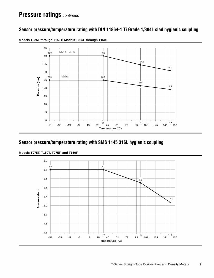
Pressure ratings continued
Sensor pressure/temperature rating with DIN 11864-1 Ti Grade 1/304L clad hygienic coupling
Sensor pressure/temperature rating with SMS 1145 316L hygienic coupling
Models T025T through T150T; Models T025F through T150F
Models T075T, T150T, T075F, and T150F
���� ����
����
����
���� ����
����
����
�
�
��
��
��
��
��
��
��
��
�� �� �� � �� �� �� � �� �� ��� ��� ��� ���
� �� � ��
� ��
����� ���
Temperature (°C)
Pre
ssu
re (
bar
)
��� ���
���
���
���
��
���
��
���
���
��
���
��
��� ��� ��� �� �� � �� �� �� �� ��� �� ��� ���
� ������
Temperature (°C)
Pre
ssu
re (
bar
)

10 T-Series Straight-Tube Coriolis Flow and Density Meters
Pressure ratings continued
Sensor pressure/temperature rating with ISO 2853 (IDF) 316L process fittings
Sensor pressure/temperature rating with EN1092-1 & DIN F316/316L socket weld flanges
Models T075T, T150T, T075F, and T150F
Models T025T through T150T; Models T075F through T150F
��� ���
���
���
���
���
��
���
���
���
���
��
���
���
����
��� ��� ��� �� �� �� � �� �� ��� ��� �� ��
�� ������
Temperature (°C)
Pre
ssu
re (
bar
)
���� ���� ��������
���� ����
����
����
�
�
�
��
��
���
��
��� ��� ��� �� �� � � �� �� �� ��� �� �� ���
����
��
��� ����
Temperature (°C)
Pre
ssu
re (
bar
)

T-Series Straight-Tube Coriolis Flow and Density Meters 11
Environmental effects
Vibration limits
Sanitary standards
Process temperature effect Process temperature effect is defined as the worst-case zero offset due to process fluid temperature change away from the zeroing temperature.
All models 0.002% of maximum flow rate per °C
Pressure effect Pressure effect is defined as the change in sensor flow sensitivity due to process pressure change away from the calibration pressure. Pressure effect can be corrected.
All models None
Meets IEC 68.2.6, endurance sweep, 5 to 2000 Hz, 50 sweep cycles at 1.0 g
For sanitary applications, Micro Motion T-Series sensors with sanitary fittings feature a standard 32 µ-inch Ra (0.8 µ-meter) tube surface finish, with 15 µ-inch Ra (0.38 µ-meter) surface finish available as an option.
ASME The Micro Motion T-Series sensor design is based on the ASME Bioprocessing Equipment Standard – 1997. With sanitary fittings, these sensors meet the ASME Bioprocessing Equipment Standard.
3-A Micro Motion T-Series sensors with sanitary fittings meet 3-A Sanitary Standards for Milk and Dairy Products.
USDA Micro Motion T-Series sensors with sanitary fittings are acceptable for use in dairy plants and are approved for USDA grading service.
EHEDG Micro Motion T-Series sensors with sanitary fittings are approved by the European Hygienic Equipment Design Group. Sensors comply with the hygienic criteria of Machinery Directive 98/37/EC, annex 1 (additional essential health and safety requirements for certain categories of machinery), section 2.1 (agri-foodstuffs machinery). Test results show that Micro Motion T-Series sensors can be cleaned in place at least as well as the reference pipe.

12 T-Series Straight-Tube Coriolis Flow and Density Meters
Hazardous area classifications
UL
Sensors with junction box Ambient temperature: +131 °F (+55 °C) maximum
Class I, Div. 1, Groups C and D
Class I, Div. 2, Groups A, B, C, and D
Class II, Div.1, Groups E, F, and G
Sensors with integral core processor or transmitter
Ambient temperature: –40 to +131 °F (–40 to +55 °C)
Class I, Div. 1, Groups C and D
Class I, Div. 2, Groups A, B, C, and D
Class II, Div.1, Groups E, F, and G
CSA
Sensors with junction box Ambient temperature: +140 °F (+60 °C) maximum
Class I, Div. 1, Groups C and D
Class I, Div. 2, Groups A, B, C, and D
Class II, Div.1, Groups E, F, and G
Sensors with integral core processor or transmitter
Ambient temperature: –40 to +140 °F (–40 to +60 °C)
Class I, Div. 1, Groups C and D
Class I, Div. 2, Groups A, B, C, and D
Class II, Div.1, Groups E, F, and G

T-Series Straight-Tube Coriolis Flow and Density Meters 13
Hazardous area classifications continued
ATEX(1)
(1) The ATEX "T" rating is defined as the maximum surface temperature of the flowmeter. The "T" rating and the ambient temperature restrict the maximum allowable temperature of the process fluid (shown in the graphs above).
Models T075 and T100 with junction box 0575 II 2G Ex ib IIC T1–T6 Gb
II 2D Ex ib IIIC T(1) °C Db IP66
Model T150 with junction box 0575 II 2G Ex ib IIB T1–T6 Gb
II 2D ib IIIC T(1) °C Db IP66
The maximum surface temperature for dust is as follows: T6:T 80°C, T5:T 95°C, T4:T 130°C, T3 to T1:T 182°C.
Models T025, T050, T075, and T100 with integral core processor
0575 II 2G Ex ib IIC T1–T5 Gb
II 2D ib IIIC T(1) °C Db IP66
Model T150 with integral core processor 0575 II 2G Ex ib IIB T1–T5 Gb
II 2D ib IIIC T(1) °C Db IP66
The maximum surface temperature for dust is as follows: T5:T 95°C, T4:T 130°C, T3 to T1:T 182°C.
Process fluid temperature (°C)
Max
. am
bie
nt
tem
per
atu
re (
°C)
Process fluid temperature (°C)
Max
. am
bie
nt
tem
per
atu
re (
°C)

14 T-Series Straight-Tube Coriolis Flow and Density Meters
Hazardous approvals continued
ATEX(1)
(1) The ATEX "T" rating is defined as the maximum surface temperature of the flowmeter. The "T" rating and the ambient temperature restrict the maximum allowable temperature of the process fluid (shown in the graphs above).
Models T025, T050, T075, and T100 with Model 1700/2700 transmitter with display
0575 II 2G Ex ib IIB+H2 T1–T5
II 2D Ex tD A21 IP66 T(1) °C
Models T025, T050, T075, and T100 withModel 1700/2700 transmitter without display
0575 II 2G Ex ib IIC T1–T5
II 2D Ex tD A21 IP66 T(1) °C
Model T150 with Model 1700/2700 transmitter 0575 II 2G Ex ib IIB T1–T5
II 2D Ex tD A21 IP66 T(1) °C
The maximum surface temperature for dust is as follows: T5:T 95°C, T4:T 130°C, T3 to T1:T 182°C.
Models T025, T050, T075, and T100 with Model 1700/2700 transmitter with THUM adapater and with display
0575 II 2G Ex ib IIB+H2 T1–T4
Models T025, T050, T075, and T100 withModel 1700/2700 transmitter with THUM adapter and without display
0575 II 2G Ex ib IIC T1–T4
Model T150 with Model 1700/2700 transmitter with THUM adapter
0575 II 2G Ex ib IIB T1–T5
The maximum surface temperature for dust is as follows: T5:T 95°C, T4:T 130°C, T3 to T1:T 182°C.
Process fluid temperature (°C)
Max
. am
bie
nt
tem
per
atu
re (
°C)
Process fluid temperature (°C)
Max
. am
bie
nt
tem
per
atu
re (
°C)

T-Series Straight-Tube Coriolis Flow and Density Meters 15
Materials of construction
Weight
Wetted parts(1)
(1) General corrosion guides do not account for cyclical stress, and therefore should not be relied upon when choosing a wetted material for your Micro Motion sensor. Please refer to Micro Motion’s corrosion guide for material compatibility information.
Flow tubes Titanium ASTM Grade 9
Sanitary fittings(2)
(2) Flanges are stainless steel; wetted parts are titanium. Only titanium is in contact with process flow.
304L stainless steel and titanium ASTM Grade 1
Socket-weld flanges(2) F316/316L stainless steel and titanium ASTM Grade 5 (6AL-4V)
Sensor housing Sensor 304L stainless steel
Core processor 316L stainless steel or polyurethane-coated aluminum; NEMA 4X (IP66)
Junction box Polyurethane-coated aluminum; NEMA 4X (IP66)
Approximate weight with ANSI CL150 socket weld raised face flange
T025 T050 T075 T100 T150
lb kg lb kg lb kg lb kg lb kg
Sensor with core processor(1)
(1) Add 4 lbs (2 kg) for stainless steel core processor housing option (electronics interface codes A, B, D, and E).
14 7 16 7 33 15 58 27 137 63
Sensor with extended core processor(1) 15 7 17 8 34 16 59 27 138 63
Sensor with integrally mounted Model 1700/2700 transmitter
20 9 22 10 39 18 64 29 143 65
Sensor with junction box – – – – 32 15 57 26 136 62
Sensor with extended junction box – – – – 33 15 58 27 137 63
Approximate weight with 1/2-inch or 1-inch sanitary fitting (Tri-Clamp compatible)
T025 T050 T075 T100 T150
lb kg lb kg lb kg lb kg lb kg
Sensor with core processor(1) 12 6 14 7 33 15 55 25 131 60
Sensor with extended core processor(1) 13 6 15 7 34 16 56 25 132 60
Sensor with integrally mountedModel 1700/2700 transmitter
18 8 20 9 39 18 60 28 137 62
Sensor with junction box – – – – 32 15 54 25 130 59
Sensor with extended junction box – – – – 33 15 55 25 131 60

16 T-Series Straight-Tube Coriolis Flow and Density Meters
Dimensions
Sensor with core processor
Sensor modelNo. of flow tubes
Dimensions in inches (mm)(1)
(1) For dimensions A and B, see process fittings tables, pages 19–26.
Tube IDØC (case diameter) E M N P Q R
T025 1 0.180(4.57)
3 1/8(79)
4 1/8 (105)
5 1/4 (133)
3 1/2 (89)
10 5/8 (269)
8.88 (225)
2 11/16 (68)
T050 1 0.360(9.14)
3 1/8 (79)
5 1/2 (140)
5 1/4 (133)
3 1/2 (89)
10 5/8 (269)
8.88 (225)
2 11/16 (68)
T075 1 0.619(15.72)
4 1/8 (105)
6 1/8 (156)
5 3/4 (147)
4 1/16 (103)
11 1/8 (283)
9.44 (240)
3 3/16 (81)
T100 1 0.870(22.10)
5 1/8 (130)
11 (279)
6 1/4 (159)
4 9/16 (116)
11 5/8 (296)
9.94 (252)
3 11/16 (93)
T150 1 1.360(34.54)
7 1/8 (181)
11 (279)
7 1/4 (185)
5 9/16 (141)
12 5/8 (321)
10.94 (278)
4 11/16 (119)
Ø1 1/4(32)
2 5/8(67)
Dim. A±1/8” (3 mm)
Dim. ØB
Dim. MDim. N
Dim. ØC
1/2”–14 NPTor M20 × 1.5
female
Ø4 3/8(111)
Dim. P
Dim. Q
Dimensions in inches(mm)
Extended mount option
Dim. E
Optional 2 × 1/2”–14 NPT female purge connection with male hex plug
Dim. R
5.66(144)
T-Series Straight-Tube Coriolis Flow and Density Meters 17
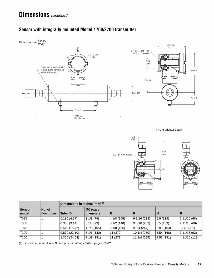
Dimensions continued
Sensor with integrally mounted Model 1700/2700 transmitter
Sensor model
No. offlow tubes
Dimensions in inches (mm)(1)
(1) For dimensions A and B, see process fittings tables, pages 19–26.
Tube IDØC (case diameter) E F N R
T025 1 0.180 (4.57) 3 1/8 (79) 4 1/8 (105) 9 3/16 (233) 5.5 (139) 2 11/16 (68)
T050 1 0.360 (9.14) 3 1/8 (79) 5 1/2 (140) 9 3/16 (233) 5.5 (139) 2 11/16 (68)
T075 1 0.619 (15.72) 4 1/8 (105) 6 1/8 (156) 9 3/4 (247) 6.03 (153) 3 3/16 (81)
T100 1 0.870 (22.10) 5 1/8 (130) 11 (279) 10 1/4 (260) 6.54 (166) 3 11/16 (93)
T150 1 1.360 (34.54) 7 1/8 (181) 11 (279) 11 1/4 (285) 7.53 (191) 4 11/16 (119)
Dim. ØB Dim. ØC
6 13/16(174)
Dim. E
Dim. F
2 × 1/2”–14 NPT orM20 × 1.5 female
Ø4 11/16(119)
Dim. A±1/8” (3 mm)
Dimensions in inches(mm)
Optional 2 × 1/2”–14 NPT female purge connection with male hex plug
Dim. R
THUM adapter detail
1/2”–14 NPT female
2.0(51)
7.27(185)
2.69(68)
Dim. N

18 T-Series Straight-Tube Coriolis Flow and Density Meters
Dimensions continued
Sensor with junction box
Sensor model(1)
(1) Models T025 and T050 are not available with junction box.
No. of flow tubes
Dimensions in inches (mm)(2)
(2) For dimensions A and B, see process fittings tables, pages 19–26.
Tube IDØC (case diameter) E F H J N Q R
T075 1 0.619 (15.72)
4 1/8 (105)
6 1/8 (156)
4 1/2 (114)
9 7/8 (251)
8 9/16 (217)
3.19(81)
8.56(217)
3 3/16 (81)
T100 1 0.870 (22.10)
5 1/8 (130)
11 (279)
5 (127)
10 3/8 (264)
9 1/16 (230)
3.69(94)
9.06(230)
3 11/16 (93)
T150 1 1.360 (34.54)
7 1/8 (181)
11 (279)
6 (152)
11 3/8 (289)
10 1/16(256)
4.69(119)
10.06(256)
4 11/16(119)
3 1/2(89)
Dim. A±1/8” (3 mm)
Dim. ØB
Dim. F
3 3/4(95)
3/4”–14 NPTfemale
Dim. E
Ø1 1/4(32)
Dim. H
Dim. ØC
Extended mount option
Dimensions in inches(mm)
Optional 2 × 1/2”–14 NPT female purge connection with male hex plug
Dim. R
Dim. Q
5.66(144)
Dim. N

T-Series Straight-Tube Coriolis Flow and Density Meters 19
Fitting options
Fittings listed here are standard options. Other types of fittings are available. The face to face dimensions for any custom fittings ordered using a 998 or 999 fitting code are not represented in this table. It is necessary to confirm face to face dimensions of these fittings at time of ordering. Contact your local Micro Motion representative.
Model T025T
Model T025F
Code Description Dim. A Dim. B
525 DN15 PN40 EN 1092-1 F316/F316L Weld neck flange Form B1 13.65 (347) 3 3/4 (95)
526 DN15 PN100 EN 1092-1 F316/F316L Weld neck flange Form B2 13.97 (355) 4 1/8 (105)
613 1/2-inch CL150 ASME B16.5 F316/F316L Socket weld flange
Raised face 13.31 (338) 3 1/2 (89)
614 1/2-inch CL300 ASME B16.5 F316/F316L Socket weld flange
Raised face 13.83 (351) 3 3/4 (95)
615 1/2-inch CL600 ASME B16.5 F316/F316L Socket weld flange
Raised face 13.95 (351) 3 3/4 (95)
616 DN15 PN40 DIN 2526 F316/F316L Socket weld flange
Type C face 13.65 (347) 3 3/4 (95)
617 DN15 PN100 DIN 2526 F316/F316L Socket weld flange
Type E face 13.97 (355) 4 1/8 (105)
621 1/2-inch Tri-Clamp compatible
Ti grade 1 clad to 304L backing
Hygienic fitting 13.92 (354) 1 (25)
636 #8 VCO Ti grade 1 clad to 304L backing
Swagelok compatible fitting
1/2-inch NPT female adapter
18.67 (474) —
637 #8 VCO Ti grade 1 clad to 304L backing
Swagelok compatible fitting
15.13 (384) —
650 DN15 PN40 DIN 2512 F316/F316L Socket weld flange
Type N grooved face
13.65 (347) 3 3/4 (95)
654 DN15 PN40 EN 1092-1 F316/F316L Weld neck flange Form D 13.65 (347) 3 3/4 (95)
670 DN10 DIN11851 Ti grade 1 clad to 304L backing
Hygienic coupling
13.93 (354) Rd 28 × 1/8
671 DN15 DIN11851 Ti grade 1 clad to 304L backing
Hygienic coupling
13.93 (354) Rd 34 × 1/8
676 DN15 DIN11864-1A Ti grade 1 clad to 304L backing
Hygienic coupling
13.89 (353) Rd 34 × 1/8
781 15mm 20K JIS B 2220 F316/F316L Socket weld flange
13.64 (346) 3 3/4 (95)
Code Description Dim. A Dim. B
621 1/2-inch Tri-Clamp compatible
Ti grade 1 clad to 304L backing
Hygienic fitting 13.92 (354) 1 (25)
670 DN10 DIN11851 Ti grade 1 clad to 304L backing
Hygienic coupling
13.93 (354) Rd 28 × 1/8
671 DN15 DIN11851 Ti grade 1 clad to 304L backing
Hygienic coupling
13.93 (354) Rd 34 × 1/8
676 DN15 DIN11864-1A Ti grade 1 clad to 304L backing
Hygienic coupling
13.89 (353) Rd 34 × 1/8

20 T-Series Straight-Tube Coriolis Flow and Density Meters
Fitting options continued
Model T050T
Model T050F
Code Description Dim. A Dim. B
525 DN15 PN40 EN 1092-1 F316/F316L Weld neck flange Form B1 16.09 (409) 3 3/4 (95)
526 DN15 PN100 EN 1092-1 F316/F316L Weld neck flange Form B2 16.41 (417) 4 1/8 (105)
613 1/2-inch CL150 ASME B16.5 F316/F316L Socket weld flange
Raised face 15.75 (400) 3 1/2 (89)
614 1/2-inch CL300 ASME B16.5 F316/F316L Socket weld flange
Raised face 16.27 (413) 3 3/4 (95)
615 1/2-inch CL600 ASME B16.5 F316/F316L Socket weld flange
Raised face 16.39 (417) 3 3/4 (95)
616 DN15 PN40 DIN 2526 F316/F316L Socket weld flange
Type C face 16.09 (409) 3 3/4 (95)
617 DN15 PN100 DIN 2526 F316/F316L Socket weld flange
Type E face 16.41 (417) 4 1/8 (105)
621 1/2-inch Tri-Clamp compatible
Ti grade 1 clad to 304L backing
Hygienic fitting 16.37 (416) 1 (25)
638 #12 VCO Ti grade 1 clad to 304L backing
Swagelok compatible fitting
3/4-inch NPT female adapter
21.60 (549) —
639 #12 VCO Ti grade 1 clad to 304L backing
Swagelok compatible fitting
17.74 (451) —
650 DN15 PN40 DIN 2512 F316/F316L Socket weld flange
Type N grooved face
16.09 (409) 3 3/4 (95)
654 DN15 PN40 EN 1092-1 F316/F316L Weld neck flange Form D 16.09 (409) 3 3/4 (95)
671 DN15 DIN11851 Ti grade 1 clad to 304L backing
Hygienic coupling
16.37 (416) Rd 34 × 1/8
676 DN15 DIN11864-1A Ti grade 1 clad to 304L backing
Hygienic coupling
16.37 (416) Rd 34 × 1/8
781 15mm 20K JIS B 2220 F316/F316L Socket weld flange
16.08 (409) 3 3/4 (95)
Code Description Dim. A Dim. B
621 1/2-inch Tri-Clamp compatible
Ti grade 1 clad to 304L backing
Hygienic fitting 16.37 (416) 1 (25)
671 DN15 DIN11851 Ti grade 1 clad to 304L backing
Hygienic coupling
16.37 (416) Rd 34 × 1/8
676 DN15 DIN11864-1A Ti grade 1 clad to 304L backing
Hygienic coupling
16.37 (416) Rd 34 × 1/8

T-Series Straight-Tube Coriolis Flow and Density Meters 21
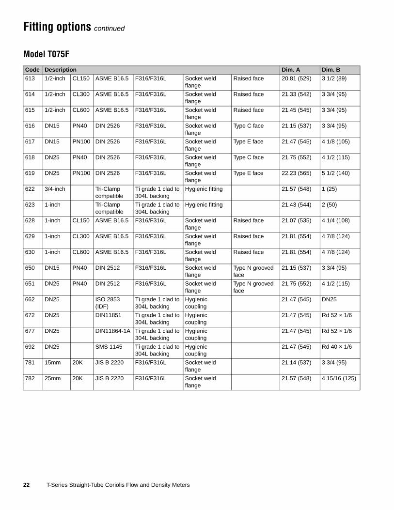
Fitting options continued
Model T075T
Code Description Dim. A Dim. B
525 DN15 PN40 EN 1092-1 F316/F316L Weld neck flange Form B1 21.15 (537) 3 3/4 (95)
526 DN15 PN100 EN 1092-1 F316/F316L Weld neck flange Form B2 21.47 (545) 4 1/8 (105)
527 DN25 PN40 EN 1092-1 F316/F316L Weld neck flange Form B1 21.75 (552) 4 1/2 (115)
528 DN25 PN100 EN 1092-1 F316/F316L Weld neck flange Form B2 22.23 (565) 5 1/2 (140)
613 1/2-inch CL150 ASME B16.5 F316/F316L Socket weld flange
Raised face 20.81 (529) 3 1/2 (89)
614 1/2-inch CL300 ASME B16.5 F316/F316L Socket weld flange
Raised face 21.33 (542) 3 3/4 (95)
615 1/2-inch CL600 ASME B16.5 F316/F316L Socket weld flange
Raised face 21.45 (545) 3 3/4 (95)
616 DN15 PN40 DIN 2526 F316/F316L Socket weld flange
Type C face 21.15 (537) 3 3/4 (95)
617 DN15 PN100 DIN 2526 F316/F316L Socket weld flange
Type E face 21.47 (545) 4 1/8 (105)
618 DN25 PN40 DIN 2526 F316/F316L Socket weld flange
Type C face 21.75 (552) 4 1/2 (115)
619 DN25 PN100 DIN 2526 F316/F316L Socket weld flange
Type E face 22.23 (565) 5 1/2 (140)
622 3/4-inch Tri-Clamp compatible
Ti grade 1 clad to 304L backing
Hygienic fitting 21.57 (548) 1 (25)
623 1-inch Tri-Clamp compatible
Ti grade 1 clad to 304L backing
Hygienic fitting 21.43 (544) 2 (50)
628 1-inch CL150 ASME B16.5 F316/F316L Socket weld flange
Raised face 21.07 (535) 4 1/4 (108)
629 1-inch CL300 ASME B16.5 F316/F316L Socket weld flange
Raised face 21.81 (554) 4 7/8 (124)
630 1-inch CL600 ASME B16.5 F316/F316L Socket weld flange
Raised face 21.81 (554) 4 7/8 (124)
650 DN15 PN40 DIN 2512 F316/F316L Socket weld flange
Type N grooved face
21.15 (537) 3 3/4 (95)
651 DN25 PN40 DIN 2512 F316/F316L Socket weld flange
Type N grooved face
21.75 (552) 4 1/2 (115)
654 DN15 PN40 EN 1092-1 F316/F316L Weld neck flange Form D 21.15 (537) 3 3/4 (95)
655 DN25 PN40 EN 1092-1 F316/F316L Weld neck flange Form D 21.75 (552) 4 1/2 (115)
662 DN25 ISO 2853 (IDF)
Ti grade 1 clad to 304L backing
Hygienic coupling
21.47 (545) DN25
672 DN25 DIN11851 Ti grade 1 clad to 304L backing
Hygienic coupling
21.47 (545) Rd 52 × 1/6
677 DN25 DIN11864-1A Ti grade 1 clad to 304L backing
Hygienic coupling
21.47 (545) Rd 52 × 1/6
692 DN25 SMS 1145 Ti grade 1 clad to 304L backing
Hygienic coupling
21.47 (545) Rd 40 × 1/6
781 15mm 20K JIS B 2220 F316/F316L Socket weld flange
21.14 (537) 3 3/4 (95)
782 25mm 20K JIS B 2220 F316/F316L Socket weld flange
21.57 (548) 4 15/16 (125)
22 T-Series Straight-Tube Coriolis Flow and Density Meters
Fitting options continued
Model T075F
Code Description Dim. A Dim. B
613 1/2-inch CL150 ASME B16.5 F316/F316L Socket weld flange
Raised face 20.81 (529) 3 1/2 (89)
614 1/2-inch CL300 ASME B16.5 F316/F316L Socket weld flange
Raised face 21.33 (542) 3 3/4 (95)
615 1/2-inch CL600 ASME B16.5 F316/F316L Socket weld flange
Raised face 21.45 (545) 3 3/4 (95)
616 DN15 PN40 DIN 2526 F316/F316L Socket weld flange
Type C face 21.15 (537) 3 3/4 (95)
617 DN15 PN100 DIN 2526 F316/F316L Socket weld flange
Type E face 21.47 (545) 4 1/8 (105)
618 DN25 PN40 DIN 2526 F316/F316L Socket weld flange
Type C face 21.75 (552) 4 1/2 (115)
619 DN25 PN100 DIN 2526 F316/F316L Socket weld flange
Type E face 22.23 (565) 5 1/2 (140)
622 3/4-inch Tri-Clamp compatible
Ti grade 1 clad to 304L backing
Hygienic fitting 21.57 (548) 1 (25)
623 1-inch Tri-Clamp compatible
Ti grade 1 clad to 304L backing
Hygienic fitting 21.43 (544) 2 (50)
628 1-inch CL150 ASME B16.5 F316/F316L Socket weld flange
Raised face 21.07 (535) 4 1/4 (108)
629 1-inch CL300 ASME B16.5 F316/F316L Socket weld flange
Raised face 21.81 (554) 4 7/8 (124)
630 1-inch CL600 ASME B16.5 F316/F316L Socket weld flange
Raised face 21.81 (554) 4 7/8 (124)
650 DN15 PN40 DIN 2512 F316/F316L Socket weld flange
Type N grooved face
21.15 (537) 3 3/4 (95)
651 DN25 PN40 DIN 2512 F316/F316L Socket weld flange
Type N grooved face
21.75 (552) 4 1/2 (115)
662 DN25 ISO 2853 (IDF)
Ti grade 1 clad to 304L backing
Hygienic coupling
21.47 (545) DN25
672 DN25 DIN11851 Ti grade 1 clad to 304L backing
Hygienic coupling
21.47 (545) Rd 52 × 1/6
677 DN25 DIN11864-1A Ti grade 1 clad to 304L backing
Hygienic coupling
21.47 (545) Rd 52 × 1/6
692 DN25 SMS 1145 Ti grade 1 clad to 304L backing
Hygienic coupling
21.47 (545) Rd 40 × 1/6
781 15mm 20K JIS B 2220 F316/F316L Socket weld flange
21.14 (537) 3 3/4 (95)
782 25mm 20K JIS B 2220 F316/F316L Socket weld flange
21.57 (548) 4 15/16 (125)
T-Series Straight-Tube Coriolis Flow and Density Meters 23
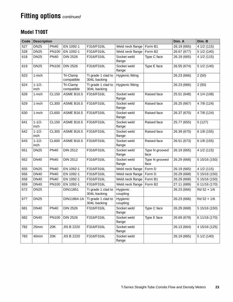
Fitting options continued
Model T100T
Code Description Dim. A Dim. B
527 DN25 PN40 EN 1092-1 F316/F316L Weld neck flange Form B1 26.19 (665) 4 1/2 (115)
528 DN25 PN100 EN 1092-1 F316/F316L Weld neck flange Form B2 26.67 (677) 5 1/2 (140)
618 DN25 PN40 DIN 2526 F316/F316L Socket weld flange
Type C face 26.19 (665) 4 1/2 (115)
619 DN25 PN100 DIN 2526 F316/F316L Socket weld flange
Type E face 26.55 (674) 5 1/2 (140)
623 1-inch Tri-Clamp compatible
Ti grade 1 clad to 304L backing
Hygienic fitting 26.23 (666) 2 (50)
624 1-1/2-inch
Tri-Clamp compatible
Ti grade 1 clad to 304L backing
Hygienic fitting 26.23 (666) 2 (50)
628 1-inch CL150 ASME B16.5 F316/F316L Socket weld flange
Raised face 25.51 (648) 4 1/4 (108)
629 1-inch CL300 ASME B16.5 F316/F316L Socket weld flange
Raised face 26.25 (667) 4 7/8 (124)
630 1-inch CL600 ASME B16.5 F316/F316L Socket weld flange
Raised face 26.37 (670) 4 7/8 (124)
641 1-1/2-inch
CL150 ASME B16.5 F316/F316L Socket weld flange
Raised face 25.77 (655) 5 (127)
642 1-1/2-inch
CL300 ASME B16.5 F316/F316L Socket weld flange
Raised face 26.39 (670) 6 1/8 (155)
643 1-1/2-inch
CL600 ASME B16.5 F316/F316L Socket weld flange
Raised face 26.51 (673) 6 1/8 (155)
651 DN25 PN40 DIN 2512 F316/F316L Socket weld flange
Type N grooved face
26.19 (665) 4 1/2 (115)
652 DN40 PN40 DIN 2512 F316/F316L Socket weld flange
Type N grooved face
26.29 (668) 5 15/16 (150)
655 DN25 PN40 EN 1092-1 F316/F316L Weld neck flange Form D 26.19 (665) 4 1/2 (115)
656 DN40 PN40 EN 1092-1 F316/F316L Weld neck flange Form D 26.29 (668) 5 15/16 (150)
658 DN40 PN40 EN 1092-1 F316/F316L Weld neck flange Form B1 26.29 (668) 5 15/16 (150)
659 DN40 PN100 EN 1092-1 F316/F316L Weld neck flange Form B2 27.11 (689) 6 11/16 (170)
672 DN25 DIN11851 Ti grade 1 clad to 304L backing
Hygienic coupling
26.23 (666) Rd 52 × 1/6
677 DN25 DIN11864-1A Ti grade 1 clad to 304L backing
Hygienic coupling
26.23 (666) Rd 52 × 1/6
681 DN40 PN40 DIN 2526 F316/F316L Socket weld flange
Type C face 26.29 (668) 5 15/16 (150)
682 DN40 PN100 DIN 2526 F316/F316L Socket weld flange
Type E face 26.69 (678) 6 11/16 (170)
782 25mm 20K JIS B 2220 F316/F316L Socket weld flange
26.13 (664) 4 15/16 (125)
783 40mm 20K JIS B 2220 F316/F316L Socket weld flange
26.19 (665) 5 1/2 (140)

24 T-Series Straight-Tube Coriolis Flow and Density Meters
Fitting options continued
Model T100F
Code Description Dim. A Dim. B
618 DN25 PN40 DIN 2526 F316/F316L Socket weld flange
Type C face 26 3/16 (665) 4 1/2 (115)
619 DN25 PN100 DIN 2526 F316/F316L Socket weld flange
Type E face 26 9/16 (674) 5 1/2 (140)
623 1-inch Tri-Clamp compatible
Ti grade 1 clad to 304L backing
Hygienic fitting 26 1/4 (668) 2 (50)
624 1-1/2-inch
Tri-Clamp compatible
Ti grade 1 clad to 304L backing
Hygienic fitting 26 1/4 (666) 2 (50)
628 1-inch CL150 ASME B16.5 F316/F316L Socket weld flange
Raised face 25 1/2 (648) 4 1/4 (108)
629 1-inch CL300 ASME B16.5 F316/F316L Socket weld flange
Raised face 26 1/4 (667) 4 7/8 (124)
630 1-inch CL600 ASME B16.5 F316/F316L Socket weld flange
Raised face 26 3/8 (670) 4 7/8 (124)
641 1-1/2-inch
CL150 ASME B16.5 F316/F316L Socket weld flange
Raised face 25 3/4 (655) 5 (127)
642 1-1/2-inch
CL300 ASME B16.5 F316/F316L Socket weld flange
Raised face 26 3/8 (670) 6 1/8 (155)
651 DN25 PN40 DIN 2512 F316/F316L Socket weld flange
Type N grooved face
26 3/16 (665) 4 1/2 (115)
652 DN40 PN40 DIN 2512 F316/F316L Socket weld flange
Type N grooved face
26 5/16 (668) 5 15/16 (150)
672 DN25 DIN11851 Ti grade 1 clad to 304L backing
Hygienic coupling
26 1/4 (666) Rd 52 × 1/6
677 DN25 DIN11864-1A Ti grade 1 clad to 304L backing
Hygienic coupling
26 1/4 (667) Rd 52 × 1/6
681 DN40 PN40 DIN 2526 F316/F316L Socket weld flange
Type C face 26 5/16 (668) 5 15/16 (150)
682 DN40 PN100 DIN 2526 F316/F316L Socket weld flange
Type E face 26 11/16 (678) 6 11/16 (170)
782 25mm 20K JIS B 2220 F316/F316L Socket weld flange
26 1/8 (664) 4 15/16 (125)
783 40mm 20K JIS B 2220 F316/F316L Socket weld flange
26 3/16 (665) 5 1/2 (140)

T-Series Straight-Tube Coriolis Flow and Density Meters 25
Fitting options continued
Model T150T
Code Description Dim. A Dim. B
624 1-1/2-inch
Tri-Clamp compatible
Ti grade 1 clad to 304L backing
Hygienic fitting 32.04 (814) 2 (50)
625 2-inch Tri-Clamp compatible
Ti grade 1 clad to 304L backing
Hygienic fitting 32.04 (814) 2 1/2 (64)
641 1-1/2-inch
CL150 ASME B16.5 F316/F316L Socket weld flange
Raised face 31.46 (799) 5 (127)
642 1-1/2-inch
CL300 ASME B16.5 F316/F316L Socket weld flange
Raised face 32.08 (815) 6 1/8 (155)
643 1-1/2-inch
CL600 ASME B16.5 F316/F316L Socket weld flange
Raised face 32.32 (821) 6 1/8 (155)
644 2-inch CL150 ASME B16.5 F316/F316L Socket weld flange
Raised face 31.68 (805) 6 (152)
645 2-inch CL300 ASME B16.5 F316/F316L Socket weld flange
Raised face 32.30 (820) 6 1/2 (165)
646 2-inch CL600 ASME B16.5 F316/F316L Socket weld flange
Raised face 32.56 (827) 6 1/2 (165)
652 DN40 PN40 DIN 2512 F316/F316L Socket weld flange
Type N grooved face
31.74 (806) 5 7/8 (150)
653 DN50 PN40 DIN 2512 F316/F316L Socket weld flange
Type N grooved face
32.02 (813) 6 1/2 (165)
656 DN40 PN40 EN 1092-1 F316/F316L Weld neck flange Form D 31.74 (806) 5 7/8 (150)
657 DN50 PN40 EN 1092-1 F316/F316L Weld neck flange Form D 32.02 (813) 6 1/2 (165)
658 DN40 PN40 EN 1092-1 F316/F316L Weld neck flange Form B1 31.74 (806) 5 7/8 (150)
659 DN40 PN100 EN 1092-1 F316/F316L Weld neck flange Form B2 32.56 (827) 6 11/16 (170)
660 DN50 PN40 EN 1092-1 F316/F316L Weld neck flange Form B1 32.02 (813) 6 1/2 (165)
661 DN50 PN100 EN 1092-1 F316/F316L Weld neck flange Form B2 32.84 (834) 7 11/16 (195)
663 DN51 ISO 2853 (IDF)
Ti grade 1 clad to 304L backing
Hygienic coupling
32.04 (814) DN51
673 DN40 DIN11851 Ti grade 1 clad to 304L backing
Hygienic coupling
32.60 (828) Rd 65 × 1/6
674 DN50 DIN11851 Ti grade 1 clad to 304L backing
Hygienic coupling
32.04 (814) Rd 78 × 1/6
678 DN50 DIN11864-1A Ti grade 1 clad to 304L backing
Hygienic coupling
32.04 (814) Rd 78 × 1/6
681 DN40 PN40 DIN 2526 F316/F316L Socket weld flange
Type C face 31.74 (806) 5 7/8 (150)
682 DN40 PN100 DIN 2526 F316/F316L Socket weld flange
Type E face 32.38 (822) 6 11/16 (170)
683 DN50 PN40 DIN 2526 F316/F316L Socket weld flange
Type C face 32.02 (813) 6 1/2 (165)
684 DN50 PN100 DIN 2526 F316/F316L Socket weld flange
Type E face 32.66 (829) 7 11/16 (195)
693 DN51 SMS 1145 Ti grade 1 clad to 304L backing
Hygienic coupling
32.04 (814) Rd 70 × 1/6
783 40mm 20K JIS B 2220 F316/F316L Socket weld flange
31.88 (810) 5 1/2 (140)
784 50mm 20K JIS B 2220 F316/F316L Socket weld flange
31.89 (810) 6 1/8 (155)

26 T-Series Straight-Tube Coriolis Flow and Density Meters
Fitting options continued
Model T150F
Code Description Dim. A Dim. B
624 1-1/2-inch
Tri-Clamp compatible
Ti grade 1 clad to 304L backing
Hygienic fitting 32.04 (814) 2 (50)
625 2-inch Tri-Clamp compatible
Ti grade 1 clad to 304L backing
Hygienic fitting 32.04 (814) 2 1/2 (64)
641 1-1/2-inch
CL150 ASME B16.5 F316/F316L Socket weld flange
Raised face 31.46 (799) 5 (127)
642 1-1/2-inch
CL300 ASME B16.5 F316/F316L Socket weld flange
Raised face 32.08 (815) 6 1/8 (155)
643 1-1/2-inch
CL600 ASME B16.5 F316/F316L Socket weld flange
Raised face 32.32 (821) 6 1/8 (155)
644 2-inch CL150 ASME B16.5 F316/F316L Socket weld flange
Raised face 31.68 (805) 6 (152)
645 2-inch CL300 ASME B16.5 F316/F316L Socket weld flange
Raised face 32.30 (820) 6 1/2 (165)
646 2-inch CL600 ASME B16.5 F316/F316L Socket weld flange
Raised face 32.56 (827) 6 1/2 (165)
652 DN40 PN40 DIN 2512 F316/F316L Socket weld flange
Type N grooved face
31.74 (806) 5 7/8 (150)
653 DN50 PN40 DIN 2512 F316/F316L Socket weld flange
Type N grooved face
32.02 (813) 6 1/2 (165)
663 DN51 ISO 2853 (IDF)
Ti grade 1 clad to 304L backing
Hygienic coupling
32.04 (814) DN51
673 DN40 DIN11851 Ti grade 1 clad to 304L backing
Hygienic coupling
32.60 (828) Rd 65 × 1/6
674 DN50 DIN11851 Ti grade 1 clad to 304L backing
Hygienic coupling
32.04 (814) Rd 78 × 1/6
678 DN50 DIN11864-1A Ti grade 1 clad to 304L backing
Hygienic coupling
32.04 (814) Rd 78 × 1/6
681 DN40 PN40 DIN 2526 F316/F316L Socket weld flange
Type C face 31.74 (806) 5 7/8 (150)
682 DN40 PN100 DIN 2526 F316/F316L Socket weld flange
Type E face 32.38 (822) 6 11/16 (170)
683 DN50 PN40 DIN 2526 F316/F316L Socket weld flange
Type C face 32.02 (813) 6 1/2 (165)
684 DN50 PN100 DIN 2526 F316/F316L Socket weld flange
Type E face 32.66 (829) 7 11/16 (195)
693 DN51 SMS 1145 Ti grade 1 clad to 304L backing
Hygienic coupling
32.04 (814) Rd 70 × 1/6
783 40mm 20K JIS B 2220 F316/F316L Socket weld flange
31.88 (810) 5 1/2 (140)
784 50mm 20K JIS B 2220 F316/F316L Socket weld flange
31.89 (810) 6 1/8 (155)

T-Series Straight-Tube Coriolis Flow and Density Meters 27
Ordering information
Model Product description
Standard sensor models
T025T Micro Motion Coriolis T-Series sensor; 1/4-inch; straight tube; titanium; 32 Ra (0.8 μm) surface finish
T050T Micro Motion Coriolis T-Series sensor; 1/2-inch; straight tube; titanium; 32 Ra (0.8 μm) surface finish
T075T Micro Motion Coriolis T-Series sensor; 3/4-inch; straight tube; titanium; 32 Ra (0.8 μm) surface finish
T100T Micro Motion Coriolis T-Series sensor; 1-inch; straight tube; titanium; 32 Ra (0.8 μm) surface finish
T150T Micro Motion Coriolis T-Series sensor; 1 1/2-inch; straight tube; titanium; 32 Ra (0.8 μm) surface finish
Improved surface finish sensor models
T025F Micro Motion Coriolis T-Series sensor; 1/4-inch; straight tube; titanium; 15 Ra (0.38 μm) surface finish
T050F Micro Motion Coriolis T-Series sensor; 1/2-inch; straight tube; titanium; 15 Ra (0.38 μm) surface finish
T075F Micro Motion Coriolis T-Series sensor; 3/4-inch; straight tube; titanium; 15 Ra (0.38 μm) surface finish
T100F Micro Motion Coriolis T-Series sensor; 1-inch; straight tube; titanium; 15 Ra (0.38 μm) surface finish
T150F Micro Motion Coriolis T-Series sensor; 1 1/2-inch; straight tube; titanium; 15 Ra (0.38 μm) surface finish
Code Fitting options
### See fittings tables on pages 19–26.
Code Case options
S 1450 psig (100 bar) containment
P(1)
(1) Not available with sensors with improved surface finish option.
Purge fittings (two 1/2-inch NPT female); 725 psig (50 bar) containment
Code Electronics interface
Q 4-wire polyurethane-painted aluminum integral core processor for remotely mounted transmitter with MVD Technology
A 4-wire stainless steel integral core processor for remotely mounted transmitter with MVD Technology
V 4-wire polyurethane-painted aluminum integral core processor with extended mount for remotely mounted transmitter with MVD Technology
B 4-wire stainless steel integral core processor with extended mount for remotely mounted transmitter with MVD Technology
C Integrally mounted Model 1700 or 2700 transmitter
R 9-wire polyurethane-painted junction box — not available with Models T025 or T050
H 9-wire polyurethane-painted junction box with extended mount — not available with Models T025 or T050
Code Conduit connections
Electronics interface codes Q, A, V, and B
B 1/2-inch NPT — no gland
E M20 — no gland
F Brass/nickel cable gland (cable diameter 0.335 to 0.394 inches [8.5 to 10 mm])
G Stainless steel cable gland (cable diameter 0.335 to 0.394 inches [8.5 to 10 mm])
Electronics interface codes R and H (9-wire junction box)
A 3/4-inch NPT — no gland
H 3/4-inch NPT with brass/nickel cable gland
J 3/4-inch NPT with stainless steel cable gland
Electronics interface code C (integrally mounted transmitter)
A No gland
Continued on next page

28 T-Series Straight-Tube Coriolis Flow and Density Meters
Ordering information continued
Code Approval
M Micro Motion standard (no approval)
N Micro Motion standard / PED compliant
U(1)
(1) Not available with models T025F or T050F.
UL
C CSA (Canada only)
A CSA (U.S.A. and Canada)
Z ATEX — Equipment Category 2 (Zone 1) / PED compliant
V(2)
(2) Available only with electronics interface option C.
ATEX — Equipment Category 3 (Zone 2) / PED compliant
3(2) IECEx Zone 2
2(2) CSA Class I Div. 2 (U.S.A. and Canada)
Code Language
A Danish installation manual
C Czech installation manual
D Dutch installation manual
E English installation manual
F French installation manual
G German installation manual
H Finnish installation manual
I Italian installation manual
J Japanese installation manual
M Chinese installation manual
N Norwegian installation manual
O Polish installation manual
S Spanish installation manual
W Swedish installation manual
B Hungarian CE requirements and English installation manual
K Slovak CE requirements and English installation manual
T Estonian CE requirements and English installation manual
U Greek CE requirements and English installation manual
L Latvian CE requirements and English installation manual
V Lithuanian CE requirements and English installation manual
Y Slovenian CE requirements and English installation manual
Code Future option 1
Z Reserved for future use
Code Future option 2
Z Reserved for future use
Code Measurement application software
Z No measurement application software
Code Factory options
Z Standard product
X ETO product
Typical model number: T025T 613 S Q B M E Z Z Z Z

T-Series Straight-Tube Coriolis Flow and Density Meters 29

30 T-Series Straight-Tube Coriolis Flow and Density Meters

T-Series Straight-Tube Coriolis Flow and Density Meters 31
�������������� � ����������������������� ������������ ����������������������������������������������� !����"##$#��� !�%���&"#�"#��' !�%���&"���(")*+��� � "#"""��)"�����,����� � "(��(����������-�� � ""�"�#���"#�.�-��� � "�#$��)#��"�
�������������� � ������������������������������� ��
/�0�� � !)��(�������������12�����2���3 � !(�(��$�$���
�������������� � �������������������� �����AustraliaChinaIndiaJapanSouth KoreaSingapore � %$"&$����#��
� %�#&#�(��($��� %��&�"�$)$���� %)�&##$$$#�"$$� %�$&#�#�)#)���� %$�&�)�#��#��
��7�������� � !�����()""""��,��8 � !�##��$����
�949 � ����#(��)��:�����;�6� � !�()")��)���
6���< � ��������(=�8��< � ������#"�(�'���� � ����)��)��
�3��� � !�()��"�$���
�0�/��0� � !)��#$)�#���
Micro Motion—The undisputed leader in flow and density measurement
WWW.micromotion.com
World-leading Micro Motion measurement solutions from Emerson Process Management deliver what you need most:
Technology leadershipMicro Motion introduced the first reliable Coriolis meter in 1977. Since that time, our ongoing product development has enabled us to provide the highest performing measurement devices available.
Product breadthFrom compact, drainable process control to high flow rate fiscal transfer—look no further than Micro Motion for the widest range of measurement solutions.
Unparalleled valueBenefit from expert phone, field, and application service and support made possible by more than 750,000 meters installed worldwide and over 30 years of flow and density measurement experience.
© 2013 Micro Motion, Inc. All rights reserved.
The Micro Motion and Emerson logos are trademarks and service marks of Emerson Electric Co. Micro Motion, ELITE, MVD, ProLink, MVD Direct Connect, and PlantWeb are marks of one of the Emerson Process Management family of companies. All other trademarks are property of their respective owners.
Micro Motion supplies this publication for informational purposes only. While every effort has been made to ensure accuracy, this publication is not intended to make performance claims or process recommendations. Micro Motion does not warrant, guarantee, or assume any legal liability for the accuracy, completeness, timeliness, reliability, or usefulness of any information, product, or process described herein. We reserve the right to modify or improve the designs or specifications of our products at any time without notice. For actual product information and recommendations, please contact your local Micro Motion representative.
For a complete list of contact information and web sites, please visit: www.emersonprocess.com/home/contacts/global