Embed Size (px)
Citation preview
J. Radiat. Res., Vol. 50, Suppl. (2009); http://jrr.jstage.jst.go.jp
J. Radiat. Res., 50: Suppl., A29-A47 (2009)
Microbeam Irradiation Facilities for Radiobiology in Japan and China
Yasuhiko KOBAYASHI1,2,3, Tomoo FUNAYAMA3, Nobuyuki HAMADA1,2,3,10,Tetsuya SAKASHITA3, Teruaki KONISHI4, Hitoshi IMASEKI4,
Keisuke YASUDA5, Masanori HATASHITA5, Keiichi TAKAGI5,Satoshi HATORI5, Keiji SUZUKI6, Motohiro YAMAUCHI6,
Shunichi YAMASHITA6, Masanori TOMITA7,Munetoshi MAEDA7,8, Katsumi KOBAYASHI8*,
Noriko USAMI8 and Lijun WU9
Heavy-ion microbeam/Light-ion microbeam/X-ray microbeam/Bystander effects/Nucleus irradia-tion/Cytoplasm irradiation.
In order to study the radiobiological effects of low dose radiation, microbeam irradiation facilities have been developed in the world. This type of facilities now becomes an essential tool for studying bystander effects and relating signaling phenomena in cells or tissues. This review introduces you available microbeam facilities in Japan and in China, to promote radiobiology using microbeam probe and to enco-urage collaborative research between radiobiologists interested in using microbeam in Japan and in China.
INTRODUCTION
Biological effect of low dose radiation has been attracted much attention in modern human society, not only due to high dependence to nuclear power as energy source, but also due to realization of human activity in space. In order to investigate mechanisms of biological effects, heterogeneity of radiation dose in cellular level became a big barrier to be overcome. This heterogeneity becomes apparent in relatively higher dose in high LET, heavy-particle irradiation than in
low LET, electron or photon irradiation. From this rational, microbeam irradiation facilities using proton or He ion were developed in 1990s in Gray laboratory, UK1) and in Columbia University, USA.2) Their pioneering works revealed various interesting results concerning heteroge-neous distribution of dose, or particle traversal per cell. Also demonstrated in the reports are non-targeted effects, or bystander effects, which was found as effects observed in cells not directly hit or irradiated, but situated nearly the cells actually received the radiation. As conventional radia-tion biology is based on the premise that only those cell nuclei exposed to radiation treatment are affected, the pres-ence of bystander effects forces a paradigm shift and reeval-uation of modern radiation biology.
So far, two types of micro irradiation facilities have been developed widely in the world, one of which is high-LET particle microbeam irradiation, and the other is soft X-ray or X-ray microbeam irradiation. Several important evidences have been discovered that have never been described in the study using conventional irradiation. For example, the studies have found that there is a mechanism to transport bystander signals between the targeted cells and neighboring untargeted cells through gap-junctional intercellular commu-nication.3) It was also shown that a single hit cell among thousands of cells could induce bystander effects, indicating that there are soluble factors, secreted from the targeted cells, which mediate non-targeted effects.4,5) Moreover, nuclear micro-irradiation as well as cytoplasmic micro-irradiation initiates bystander effects, implicating that not
*Corresponding author: Phone: +81-29-864-5655, Fax: +81-29-864-2801, E-mail: [email protected]
1Department of Quantum Biology, Division of Bioregulatory Medicine, Gumma Univ. Graduate School of Medicine, Maebashi, Gumma 371-8511, Japan; 2The 21st Century Center of Excellence (COE) Program for Biomedical Research Using Accelerator Technology; 3Microbeam Radiation Biology Group, Radiation-Applied Biology Division, Quantum Beam Science Directorate, Japan Atomic Energy Agency (JAEA), Takasaki, Gunma 370-1292, Japan; 4Dept. Technical Support and Development, National Institute of Radiological Sciences, Chiba, Chiba 263-8555, Japan; 5The Wakasa Wan Energy Research Center, Tsuruga, Fukui 914-0192, Japan; 6Atomic Bomb Disease Institute, Graduate School of Biomedical Sciences, Nagasaki University, Nagasaki, Nagasaki 852-8521, Japan; 7Cenral Research Institute of Electric Power Industry, Komae, Tokyo 201-8511, Japan; 8Photon Factory, KEK, Tsukuba, Ibaraki 305-0801, Japan; 9Key Laboratory of Ion Beam Bioengineering, Hefei, Anhui 230031, China; 10Present address: Dept. Pathology, Institute of Development, Aging and Cancer, Tohoku Univ. Sendai 980-8575, Japan.doi:10.1269/jrr.09009S
Y. Kobayashi et al.A30
J. Radiat. Res., Vol. 50, Suppl. (2009); http://jrr.jstage.jst.go.jp
only DNA damage but also dysfunction of mitochondria plays a role in generating bystander signals.6,7) It is quite clear that these findings have never been discovered without targeted micro irradiation, and thus, microbeam irradiation becomes indispensable for studying such non-targeted effects.
Soon after the construction of microbeam irradiation facilities for raidiobiology in UK and USA, a project of microbeam irradiation using heavy ions started in JAEA, Takasaki in Japan. These facilities provided concrete evidence on bystander effects and related phenomena, which turned on the explosive progress in radiobiology in low dose region. Since then, several proposals for constructing micro-beam irradiation systems have been proposed in Japan, and presently six systems are working and some more, under development or being planned. One of the characteristics in microbeam research status in Japan is that various types of radiation are available, including soft X-rays, X-rays, light ions and heavy ions. This indicates a potentiality of explo-sive development in microbeam radiobiology in Japan. This review introduces present status and characteristics of these six microbeam facilities, all of which are open to outside users under some sort of collaboration programs, in order to encourage Japanese radiobiologists for using them and to promote radiobiology in Japan. For the convenience of readers, characteristics of these facilities are summarized in one Table. Also added in this review is a microbeam facility in Hefei, China, since China is not so far located for the collaboration of Japanese scientists.
HEAVY-ION MICROBEAM SYSTEM AT JAEA-TAKASAKI FOR BIOLOGICAL STUDIES
IntroductionAdvantage associated with the use of heavy-ion micro-
beam irradiation concerns the precise detection of ion-hit position on micron-scale targets. According to the model of ion track structure, track structure of heavy ions is charac-terized by a higher ionization density in the central part of the track, called “core”, and a larger diameter of secondary electrons called “penumbra” or “delta rays”, but the range of energy deposition is no more than a few micrometers. On the
other hand, cell nuclei range from ten up to several tens of micrometers in size. Therefore, when investigating bio-logical effects together with the relationship to ion track structure, it is important to know the precise position where ion(s) hit. A precise regulation of the target position on the cell nucleus by microbeam irradiation makes it possible to obtain the information on the position of ion traversal and on cellular responses induced by ion hit simultaneously, indicating microbeam is an operative means for elucidating initial cellular responses together with the relationship with ion track structure.
Heavy ion-induced bystander effect is a phenomenon that may be of concern to astronauts exposed to space radiation during long-term space missions.8,9) On this context, the use of heavy-ion microbeam is important for assessing health risk of space radiation.
The use of heavy-ion microbeams has not been restricted to the area of radiation biology and has been applied to other areas including its use as a micro-radiosurgical tool to target specific tissue regions of biological samples,10–15) as is the case for heavy-ion radiotherapy. Heavy-ion microbeams can inactivate specific cell populations in multicellular organ-isms by targeted irradiation and allow for the investigation of their function by observing changes in the irradiated tar-gets. Similar analyses can be performed using micro laser ablation techniques. However, micro laser irradiation com-pletely eliminates target cell and tissue structures as a result of heat-induced degeneration, while we can suppress cell division and gene expression without destroying intact tissue structures and intercellular interaction by heavy-ion micro-beam irradiation. Moreover, the heavy-ion energy deposited at the Bragg peak can be controlled by adjusting the ion energy. Thus, heavy-ion microbeam irradiation can be employed in precisely controlled microsurgical operations with fewer side effects compared with micro laser ablation techniques.
Heavy-ion microbeam cell targeting system at JAEA-Takasaki
The heavy-ion microbeam system at JAEA-Takasaki employs a micrometer-sized collimator (microaperture) for
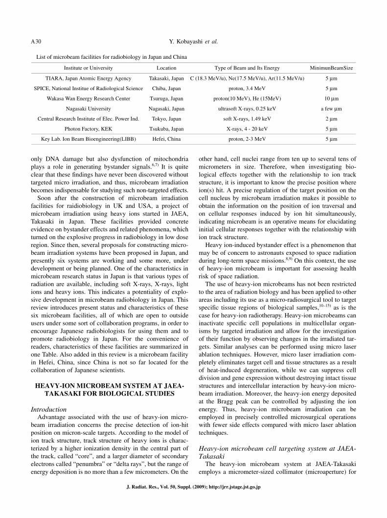
List of microbeam facilities for radiobiology in Japan and China
Institute or University Location Type of Beam and Its Energy MinimunBeamSize
TIARA, Japan Atomic Energy Agency Takasaki, Japan C (18.3 MeV/u), Ne(17.5 MeV/u), Ar(11.5 MeV/u) 5 μm
SPICE, National Institue of Radiological Science Chiba, Japan proton, 3.4 MeV 5 μm
Wakasa Wan Energy Research Center Tsuruga, Japan proton(10 MeV), He (15MeV) 10 μm
Nagasaki University Nagasaki, Japan ultrasoft X-rays, 0.25 keV a few μm
Central Research Institute of Elec. Power Ind. Tokyo, Japan soft X-rays, 1.49 keV 2 μm
Photon Factory, KEK Tsukuba, Japan X-rays, 4 - 20 keV 5 μm
Key Lab. Ion Beam Bioengineering(LIBB) Hefei, China proton, 2-3 MeV 5 μm
Microbeam Facilities in Japan and China A31
J. Radiat. Res., Vol. 50, Suppl. (2009); http://jrr.jstage.jst.go.jp
generating heavy-ion microbeams from ions accelerated using the azimuthally-varying-field (AVF) cyclotron.16–18)
This system has been used by JAEA-Takasaki group to irra-diate a variety of samples including cultured cells,16,19–21)
nematode,10) plant tissue11,15) and silkworm.12–14) The appara-tus can generate microbeams with most of the ion species accelerated by the AVF cyclotron using various microaper-ture sizes ranging from 5 to 250 μm in diameter. The ion species frequently used include carbon (18.3 MeV/u), neon (17.5 MeV/u) and argon (11.5 MeV/u). For the irradiation of biological samples, ions are extracted into air from vacuum via a 8 μm-thick polyimide window or, in case of beam sizes less than 20 μm, extracted directly into air by maintaining the vacuum of the beam line through differential pumping. Irradiated ions penetrate cell samples cultured on the plastic ion track detector CR-39 (TNF-1, 100 μm thick), and are then detected and counted by the PMT-scintillator assembly installed on the revolver of the optical microscope used for cell irradiation. The system is designed for the rapid and simultaneous detection of ion hits on cell samples by visu-alizing the track on the counter side of CR-39 base plate as etched pits using an alkaline-ethanol solution under cell cul-ture conditions (37°C, 5% CO2 and 100% humidity). The variable beam size implemented by the exchangeable microaperture enables the system for use with a variety of biological targets from cultured cells in the micrometer-scale to silkworm larva in the millimeter-scale. Cells are stained with the fluorescent vital staining dye CellTracker Orange to locate the targets, and the position of the cells is then deter-mined by image processing to generate the coordinate data-base using the “offline” microscope system, which is located away from the beam line to facilitate rapid irradiation. Following this, samples are transferred onto the “online” microscope, and then rapidly and automatically irradiated according to the coordinates stored in the database generated at the “offline” system. Because the position of beam is fixed, irradiation of sample is carried out by systematically moving each sample by the sample stage to the position of the beam. Target samples have included not only the cul-tured cells for radiobiological study, but also the root tissues of the thale-cress Arabidopsis thaliana, embryos and larvae of the silkworm Bombyx mori, and the nematode Caenorhabditis elegans, to investigate biological phenome-na pertaining to a diverse group of fields including develop-mental biology, neurobiology and plant physiology. Detailed experimental procedures are described previously.18)
Another microbeam system we are working on is newly developed focused heavy-ion microbeam system.22,23) The system is equipped with a magnetic quadrupole quadruplet lens system for higher spatial resolution and with an X, Y beam scanner for fast hitting of single ion to micron scaled samples like a biological cell. In vacuum, a microbeam gen-erated by the system had spatial resolution of less than 1 μm. To irradiate this finer microbeam to the specific region of
individual cells, a new cell targeting system was designed and installed under the beam extraction window. The system consists of Olympus IX81 full-automatic inverted micro-scope system, and the set of automatic stages for managing sample and microscope alignment. The system is settled on the mount frame that is rigidly fixed to the quadrupole qua-druplet lens for avoiding influences of vibration.
Biological applications of heavy-ion microbeamStudies of direct hit effects of heavy ions
Chinese hamster ovary (CHO) cells were targeted with 40Ar ion microbeams of 5 μm in diameter (11.5 MeV/u, LET = 1260 keV/μm), and the precise position of ion hits was determined by merged images of the cells and ion-pits etched on a CR-39 plastic ion track detector, showing that nuclear hits, comprising a single ion, and cytoplasmic hits significantly suppressed cell growth.16) In addition to mam-malian cultured cell lines, other cell types have been irradi-ated under in vitro culture conditions. As a model system representing single plant cells, tobacco BY-2 protoplasts were targeted with 12C ion microbeams 20 μm in diameter (18.3 MeV/u, LET = 121 keV/μm) to investigate the clono-genicity of targeted cells.20) As a model system for the inves-tigation of muscular dystrophy where microinjury of the plasma membrane occurs,24) single fibers isolated under in vitro culture conditions from mouse skeletal muscle were irradiated with 20Ne (12.8 MeV/u, LET = 375 keV/μm) and 40Ar (11.5 MeV/u, LET = 1260 keV/μm) ion microbeams 20 μm in diameter, and ultrastructural changes were examined using electron microscopy. We observed irregular protru-sions and invaginations in the plasma membrane, irregular disruption of microfilaments in the cytoplasm near the plasma membrane, and multiple autophagic vacuoles. These findings suggest that heavy-ion irradiation causes disruption of the cellular architecture, and the removal of which involves autophagy.24)
Studies of the bystander effectsWith less than 0.02% of confluent AG01522 fibroblasts
targeted with 20Ne (12.8 MeV/u, LET = 375 keV/μm) and 40Ar (11.5 MeV/u, 1260 keV/μm) ion microbeams 5 μm in diameter, we found that gap junctional intercellular com-munication and reactive oxygen species mediate bystander-induced micronucleus formation.19,21) Recently, with less than 0.01% of confluent AG01522 fibroblasts targeted with 12C (18.3 MeV/u, LET = 103 keV/μm), 20Ne (17.5 MeV/u, 294 keV/μm) or 20Ne (13.0 MeV/u, 375 keV/μm) ion micro-beams 20 μm in diameter, we showed that bystander effects manifested itself as inactivated clonogenic potential, a transient apoptotic response and delayed p53 phosphoryla-tion,25,26) and that gene expression profiles in bystander cells are substantially different from those in irradiated cells.27)
We have also shown bystander-induced suppression of cell proliferation in CHO cell cultures using 40Ar ion micro-beams 5 μm in diameter (11.5 MeV/u, LET = 1260 keV/
Y. Kobayashi et al.A32
J. Radiat. Res., Vol. 50, Suppl. (2009); http://jrr.jstage.jst.go.jp
μm).16) With the in vivo targeting of germline cells in the nematode using 12C ion microbeams 20 μm in diameter (LET = 120 keV/μm), we observed little, if any, bystander effects in nonirradiated bystander tissues.10)
Studies using radio-microsurgical techniquesAn example of plant physiological research by our group
concerned the investigation of root gravitropism in thale cress.11) Primary root apical tissues targeted with 12C ion microbeams 120 μm in diameter (18.3 MeV/u, LET = 110 keV/μm) significantly suppressed root elongation and curva-ture at the root tip. Irradiation of cells that would later form the lower part of the root cap following gravistimulation resulted in dramatic inhibition of root curvature, an effect not observed following irradiation of cells that would form the upper part of the root cap. Targeted exposure to narrower microbeams (40 μm in diameter) revealed that inhibition of curvature was most pronounced at the root tip, followed by cells in the lower part of the root cap. These findings suggest that the most sensitive sites related to root gravity comprise the root tip and columella cells, and that the root gravity signaling pathway traverses the lower part of the cap cells following perception.11) Recently, we also analyzed the function of the root cap and elongation zone cells in root hydrotropism using our 180-μm-diameter microbeams of 12C ions (LET = 135 keV/μm).15) Targeted irradiation of the elon-gation zone, but not the columella cells, significantly inhibit-ed the development of hydrotropic curvature. Laser ablation as another microsurgical approach revealed that columella cells are indispensable for hydrotropism. Thus we showed that both the root cap elongation zone play indispensable and functionally distinct roles in root hydrotropism.15)
To apply microbeam technology in the area of insect developmental biology, we investigated embryogenesis in the silkworm.12) To this end, various sites within the eggs were exposed to 12C ion microbeams (LET = 110–200 keV/μm) collimated using microapertures of varying diameter ranging from 60 to 250 μm. Targeted irradiation resulted in the generation of abnormal embryos which exhibited local-ized defects of organs including deletion, duplication and fusion in a manner dependent on the dose, beam size and choice of target site. Taking into account the close correla-tion between the location and frequency of these phenotypic defects on the resulting embryos and the targeted sites, we succeeded in establishing a fate map for the cellular blasto-dermal stage embryo.12) The knob-forming region in first instar larvae of the knob mutant silkworm, which exhibit knobs on the dorsal side of larva spots, were also targeted with 12C microbeams 180 μm in diameter (LET = 128 keV/μm), and knob formation was found to be suppressed at the irradiated segments.14)
To evaluate the radiation effect on individual organisms, we investigated positional radiation effects on nematode ger-mline cells.10) In this study, germline cells in the gonad were irradiated with 12C ion microbeams 20 μm in diameter (LET =
120 keV/μm). Targeted irradiation of the tip region of the gonad arm at the L4 larval stage arrested germ cell prolifer-ation, while irradiation of the pachytene region at the young gravid stage induced apoptotic cell death in the gonad. This was also observed in the c-abl-1 mutant nematode.10) Thus, radio-microsurgical approaches employing targeted irradia-tion with heavy-ion microbeams generated at JAEA-Takasaki proved to be useful in characterizing the tissue-specific, local biological response in eukaryotes.
SINGLE PARTICLE IRRADIATION SYSTEMTO CELLS: SPICE, AT NIRS
Outline of the single particle irradiation system to cells: SPICE
An electrostatic accelerator facility of NIRS supplies pro-tons and helium ion beam with a Tandetron accelerator (High Voltage Engineering Europa B.V.) at maximum ener-gies of 3.4 MeV and 5.1 MeV, respectively. In this PIXE Analysis system and Tandem Accelerator (PASTA) facility, there are four beam lines,28) and its three horizontal beam lines, conventional (in vacuo), in air and droplet29), and microbeam scanning beam line30) are available for PIXE analysis. In the fourth beam line, a single particle irradiation system to cells, SPICE has been constructed.31,32) The beam is transported upward with a 90 degrees bending magnet installed in the middle of the microbeam scanning PIXE beam line. In order to get a microbeam in SPICE, the beam is focused by a mono bloc triplet lens so as to exclude low-energy, scattered particle components as often seen in other microbeam facilities utilizing collimation methods.
Beam size measurements using CR-39The beam size was determined by irradiating a plastic
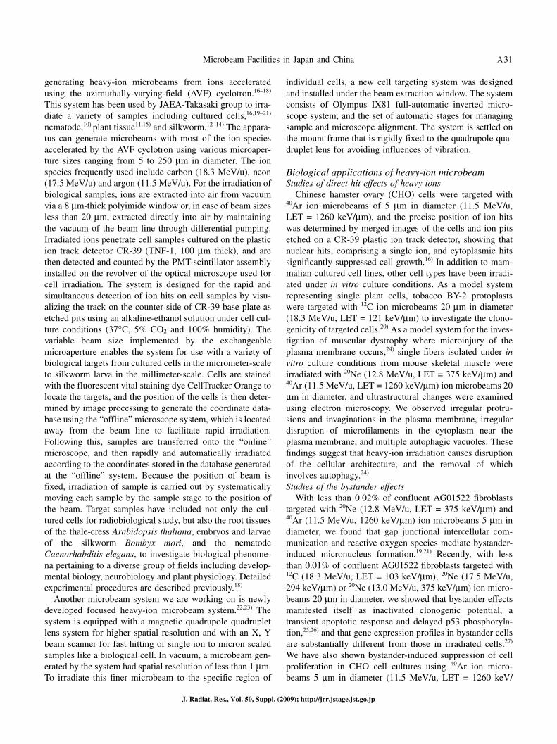
track detector, CR-39. A CR-39 (100 μm thick) was adhered to the cell dish instead of cells, and then the dish was set on the voice coil motor-driven sample stage. The gap between the beam exit window, Si3N4 membrane (1 μm thick), and the targeted CR-39 was approximately 300 μm. Then, CR-39 was etched in 7M NaOH at 70°C for 2 hours and its image was obtained by confocal laser microscope (FV1000, Olympus). Figure 1 shows an image of irradiated CR-39 after the etching procedure. For each position, protons were irradiated by moving the sample stage with 50 μm pitch. Irradiation was performed automatically according to a text file containing data on a preset number of protons and on the X-Y coordinates of the sample stage position. This system enables one to irradiate 6–8 positions per second.
Cell targeting and irradiation systemFor the routine irradiation on cells, the beam intensity is
controlled to be below 5.0 × 10⁴ protons per second. The number of protons having traveled through the cells is count-ed using a scintillation detector equipped on a microscope
Microbeam Facilities in Japan and China A33
J. Radiat. Res., Vol. 50, Suppl. (2009); http://jrr.jstage.jst.go.jp
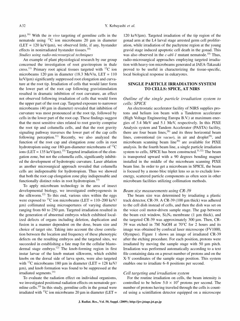
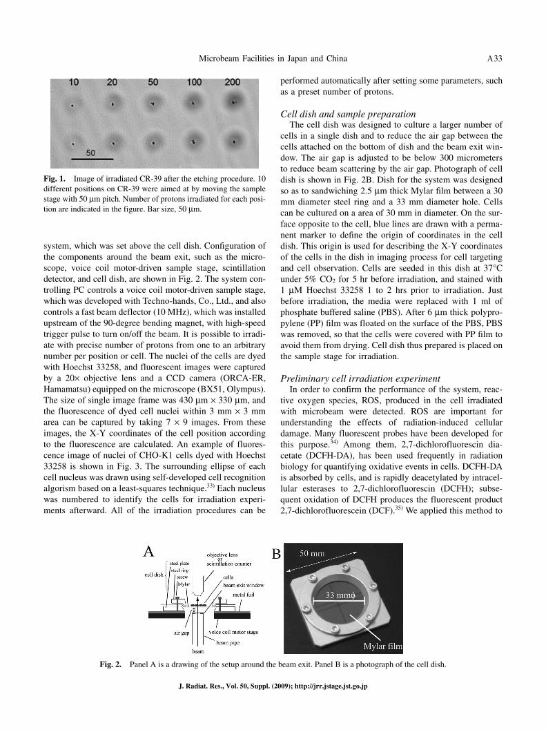
system, which was set above the cell dish. Configuration of the components around the beam exit, such as the micro-scope, voice coil motor-driven sample stage, scintillation detector, and cell dish, are shown in Fig. 2. The system con-trolling PC controls a voice coil motor-driven sample stage, which was developed with Techno-hands, Co., Ltd., and also controls a fast beam deflector (10 MHz), which was installed upstream of the 90-degree bending magnet, with high-speed trigger pulse to turn on/off the beam. It is possible to irradi-ate with precise number of protons from one to an arbitrary number per position or cell. The nuclei of the cells are dyed with Hoechst 33258, and fluorescent images were captured by a 20× objective lens and a CCD camera (ORCA-ER, Hamamatsu) equipped on the microscope (BX51, Olympus). The size of single image frame was 430 μm × 330 μm, and the fluorescence of dyed cell nuclei within 3 mm × 3 mm area can be captured by taking 7 × 9 images. From these images, the X-Y coordinates of the cell position according to the fluorescence are calculated. An example of fluores-cence image of nuclei of CHO-K1 cells dyed with Hoechst 33258 is shown in Fig. 3. The surrounding ellipse of each cell nucleus was drawn using self-developed cell recognition algorism based on a least-squares technique.33) Each nucleus was numbered to identify the cells for irradiation experi-ments afterward. All of the irradiation procedures can be
performed automatically after setting some parameters, such as a preset number of protons.
Cell dish and sample preparationThe cell dish was designed to culture a larger number of
cells in a single dish and to reduce the air gap between the cells attached on the bottom of dish and the beam exit win-dow. The air gap is adjusted to be below 300 micrometers to reduce beam scattering by the air gap. Photograph of cell dish is shown in Fig. 2B. Dish for the system was designed so as to sandwiching 2.5 μm thick Mylar film between a 30 mm diameter steel ring and a 33 mm diameter hole. Cells can be cultured on a area of 30 mm in diameter. On the sur-face opposite to the cell, blue lines are drawn with a perma-nent marker to define the origin of coordinates in the cell dish. This origin is used for describing the X-Y coordinates of the cells in the dish in imaging process for cell targeting and cell observation. Cells are seeded in this dish at 37°C under 5% CO2 for 5 hr before irradiation, and stained with 1 μM Hoechst 33258 1 to 2 hrs prior to irradiation. Just before irradiation, the media were replaced with 1 ml of phosphate buffered saline (PBS). After 6 μm thick polypro-pylene (PP) film was floated on the surface of the PBS, PBS was removed, so that the cells were covered with PP film to avoid them from drying. Cell dish thus prepared is placed on the sample stage for irradiation.
Preliminary cell irradiation experimentIn order to confirm the performance of the system, reac-
tive oxygen species, ROS, produced in the cell irradiated with microbeam were detected. ROS are important for understanding the effects of radiation-induced cellular damage. Many fluorescent probes have been developed for this purpose.34) Among them, 2,7-dichlorofluorescin dia-cetate (DCFH-DA), has been used frequently in radiation biology for quantifying oxidative events in cells. DCFH-DA is absorbed by cells, and is rapidly deacetylated by intracel-lular esterases to 2,7-dichlorofluorescin (DCFH); subse-quent oxidation of DCFH produces the fluorescent product 2,7-dichlorofluorescein (DCF).35) We applied this method to
Fig. 1. Image of irradiated CR-39 after the etching procedure. 10 different positions on CR-39 were aimed at by moving the sample stage with 50 μm pitch. Number of protons irradiated for each posi-tion are indicated in the figure. Bar size, 50 μm.
Fig. 2. Panel A is a drawing of the setup around the beam exit. Panel B is a photograph of the cell dish.
Y. Kobayashi et al.A34
J. Radiat. Res., Vol. 50, Suppl. (2009); http://jrr.jstage.jst.go.jp
detect ROS induced intracellularly with 3.4 MeV proton microbeam.
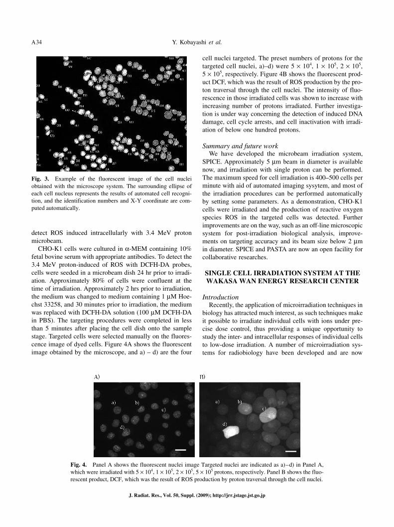
CHO-K1 cells were cultured in α-MEM containing 10% fetal bovine serum with appropriate antibodies. To detect the 3.4 MeV proton-induced of ROS with DCFH-DA probes, cells were seeded in a microbeam dish 24 hr prior to irradi-ation. Approximately 80% of cells were confluent at the time of irradiation. Approximately 2 hrs prior to irradiation, the medium was changed to medium containing 1 μM Hoe-chst 33258, and 30 minutes prior to irradiation, the medium was replaced with DCFH-DA solution (100 μM DCFH-DA in PBS). The targeting procedures were completed in less than 5 minutes after placing the cell dish onto the sample stage. Targeted cells were selected manually on the fluores-cence image of dyed cells. Figure 4A shows the fluorescent image obtained by the microscope, and a) – d) are the four
cell nuclei targeted. The preset numbers of protons for the targeted cell nuclei, a)–d) were 5 × 10⁴, 1 × 10⁵, 2 × 10⁵, 5 × 10⁵, respectively. Figure 4B shows the fluorescent prod-uct DCF, which was the result of ROS production by the pro-ton traversal through the cell nuclei. The intensity of fluo-rescence in those irradiated cells was shown to increase with increasing number of protons irradiated. Further investiga-tion is under way concerning the detection of induced DNA damage, cell cycle arrests, and cell inactivation with irradi-ation of below one hundred protons.
Summary and future workWe have developed the microbeam irradiation system,
SPICE. Approximately 5 μm beam in diameter is available now, and irradiation with single proton can be performed. The maximum speed for cell irradiation is 400–500 cells per minute with aid of automated imaging sysytem, and most of the irradiation procedures can be performed automatically by setting some parameters. As a demonstration, CHO-K1 cells were irradiated and the production of reactive oxygen species ROS in the targeted cells was detected. Further improvements are on the way, such as an off-line microscopic system for post-irradiation biological analysis, improve-ments on targeting accuracy and its beam size below 2 μm in diameter. SPICE and PASTA are now an open facility for collaborative researches.
SINGLE CELL IRRADIATION SYSTEM AT THE WAKASA WAN ENERGY RESEARCH CENTER
IntroductionRecently, the application of microirradiation techniques in
biology has attracted much interest, as such techniques make it possible to irradiate individual cells with ions under pre-cise dose control, thus providing a unique opportunity to study the inter- and intracellular responses of individual cells to low-dose irradiation. A number of microirradiation sys-tems for radiobiology have been developed and are now
Fig. 3. Example of the fluorescent image of the cell nuclei obtained with the microscope system. The surrounding ellipse of each cell nucleus represents the results of automated cell recogni-tion, and the identification numbers and X-Y coordinate are com-puted automatically.
Fig. 4. Panel A shows the fluorescent nuclei image Targeted nuclei are indicated as a) – d) in Panel A, which were irradiated with 5 × 10⁴, 1 × 10⁵, 2 × 10⁵, 5 × 10⁵ protons, respectively. Panel B shows the fluo-rescent product, DCF, which was the result of ROS production by proton traversal through the cell nuclei.
Microbeam Facilities in Japan and China A35
J. Radiat. Res., Vol. 50, Suppl. (2009); http://jrr.jstage.jst.go.jp
operational.1,2,36,37) A single-cell irradiation system is cur-rently under development at the Wakasa-wan Multi-purpose Accelerator with Synchrotron and Tandem (W-MAST).38)
Cells are irradiated using a vertical ion beam, with collima-tion achieved using a glass capillary.39) This report presents the design and construction of this single-cell irradiation system, and provides some results demonstrating the capa-bilities of the system.
Experimental facilityBeam line
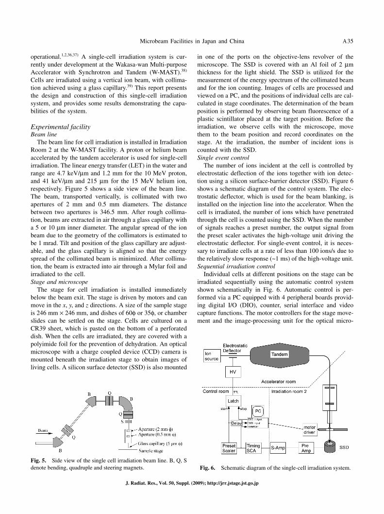
The beam line for cell irradiation is installed in Irradiation Room 2 at the W-MAST facility. A proton or helium beam accelerated by the tandem accelerator is used for single-cell irradiation. The linear energy transfer (LET) in the water and range are 4.7 keV/μm and 1.2 mm for the 10 MeV proton, and 41 keV/μm and 215 μm for the 15 MeV helium ion, respectively. Figure 5 shows a side view of the beam line. The beam, transported vertically, is collimated with two apertures of 2 mm and 0.5 mm diameters. The distance between two apertures is 346.5 mm. After rough collima-tion, beams are extracted in air through a glass capillary with a 5 or 10 μm inner diameter. The angular spread of the ion beam due to the geometry of the collimators is estimated to be 1 mrad. Tilt and position of the glass capillary are adjust-able, and the glass capillary is aligned so that the energy spread of the collimated beam is minimized. After collima-tion, the beam is extracted into air through a Mylar foil and irradiated to the cell.Stage and microscope
The stage for cell irradiation is installed immediately below the beam exit. The stage is driven by motors and can move in the x, y, and z directions. A size of the sample stage is 246 mm × 246 mm, and dishes of 60φ or 35φ, or chamber slides can be settled on the stage. Cells are cultured on a CR39 sheet, which is pasted on the bottom of a perforated dish. When the cells are irradiated, they are covered with a polyimide foil for the prevention of dehydration. An optical microscope with a charge coupled device (CCD) camera is mounted beneath the irradiation stage to obtain images of living cells. A silicon surface detector (SSD) is also mounted
in one of the ports on the objective-lens revolver of the microscope. The SSD is covered with an Al foil of 2 μm thickness for the light shield. The SSD is utilized for the measurement of the energy spectrum of the collimated beam and for the ion counting. Images of cells are processed and viewed on a PC, and the positions of individual cells are cal-culated in stage coordinates. The determination of the beam position is performed by observing beam fluorescence of a plastic scintillator placed at the target position. Before the irradiation, we observe cells with the microscope, move them to the beam position and record coordinates on the stage. At the irradiation, the number of incident ions is counted with the SSD.Single event control
The number of ions incident at the cell is controlled by electrostatic deflection of the ions together with ion detec-tion using a silicon surface-barrier detector (SSD). Figure 6 shows a schematic diagram of the control system. The elec-trostatic deflector, which is used for the beam blanking, is installed on the injection line into the accelerator. When the cell is irradiated, the number of ions which have penetrated through the cell is counted using the SSD. When the number of signals reaches a preset number, the output signal from the preset scaler activates the high-voltage unit driving the electrostatic deflector. For single-event control, it is neces-sary to irradiate cells at a rate of less than 100 ions/s due to the relatively slow response (~1 ms) of the high-voltage unit.Sequential irradiation control
Individual cells at different positions on the stage can be irradiated sequentially using the automatic control system shown schematically in Fig. 6. Automatic control is per-formed via a PC equipped with 4 peripheral boards provid-ing digital I/O (DIO), counter, serial interface and video capture functions. The motor controllers for the stage move-ment and the image-processing unit for the optical micro-
Fig. 5. Side view of the single cell irradiation beam line. B, Q, S denote bending, quadruple and steering magnets. Fig. 6. Schematic diagram of the single-cell irradiation system.
Y. Kobayashi et al.A36
J. Radiat. Res., Vol. 50, Suppl. (2009); http://jrr.jstage.jst.go.jp
scope are connected to the PC via an RS-232C interface. The DIO board is connected to a NIM module that generates a control signal for the high-voltage unit driving the electro-static deflector. Before irradiation, the position data for indi-vidual cells are input into the automatic control software. Irradiation is started after positioning of the stage. When the number of ions detected with the SSD reaches a preset number, the output signal from the preset scaler is received by the DIO board to activate the high-voltage module for the electric deflector. Then the motor controller moves the stage under automatic control to the next irradiation position. After the movement is complete, the DIO board outputs a signal to deactivate the electrostatic deflector and thereby start irradiation on the next cell. The number of protons for each cell position is recorded in the PC.
Results of experimental testsAt first, energy spectrum of the collimated beam was mea-
sured using the SSD. The helium beam with energy of 15 MeV was extracted into air through a Mylar foil of 2 μm in thickness. The glass capillary of 5 μm inner diameter was used for the measurement. The SSD was positioned in air 15 mm below the exit window. The measured energy spec-trum shows that 93% of the detected helium ions are dis-tributed near the high-energy end, forming a peak in the spectrum. In the case of the proton beam with energy of 10 MeV, 78% of the detected protons are in the peak at the high-energy end using the glass capillary of 10 μm inner diameter.
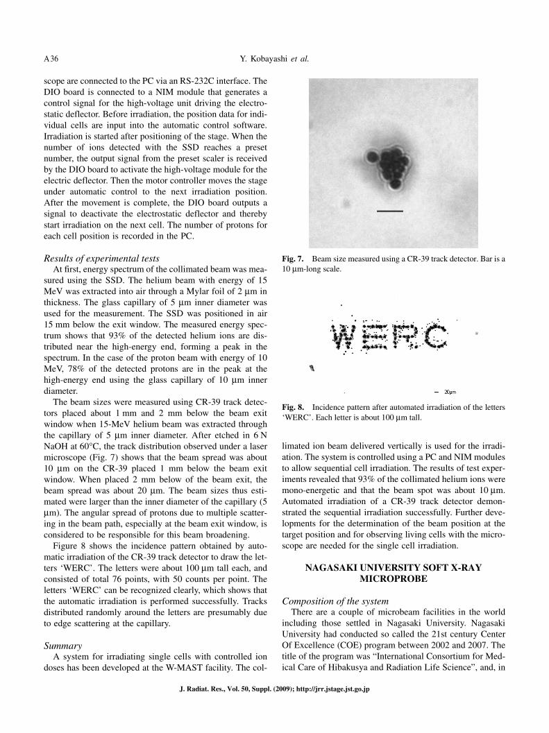
The beam sizes were measured using CR-39 track detec-tors placed about 1 mm and 2 mm below the beam exit window when 15-MeV helium beam was extracted through the capillary of 5 μm inner diameter. After etched in 6 N NaOH at 60°C, the track distribution observed under a laser microscope (Fig. 7) shows that the beam spread was about 10 μm on the CR-39 placed 1 mm below the beam exit window. When placed 2 mm below of the beam exit, the beam spread was about 20 μm. The beam sizes thus esti-mated were larger than the inner diameter of the capillary (5 μm). The angular spread of protons due to multiple scatter-ing in the beam path, especially at the beam exit window, is considered to be responsible for this beam broadening.
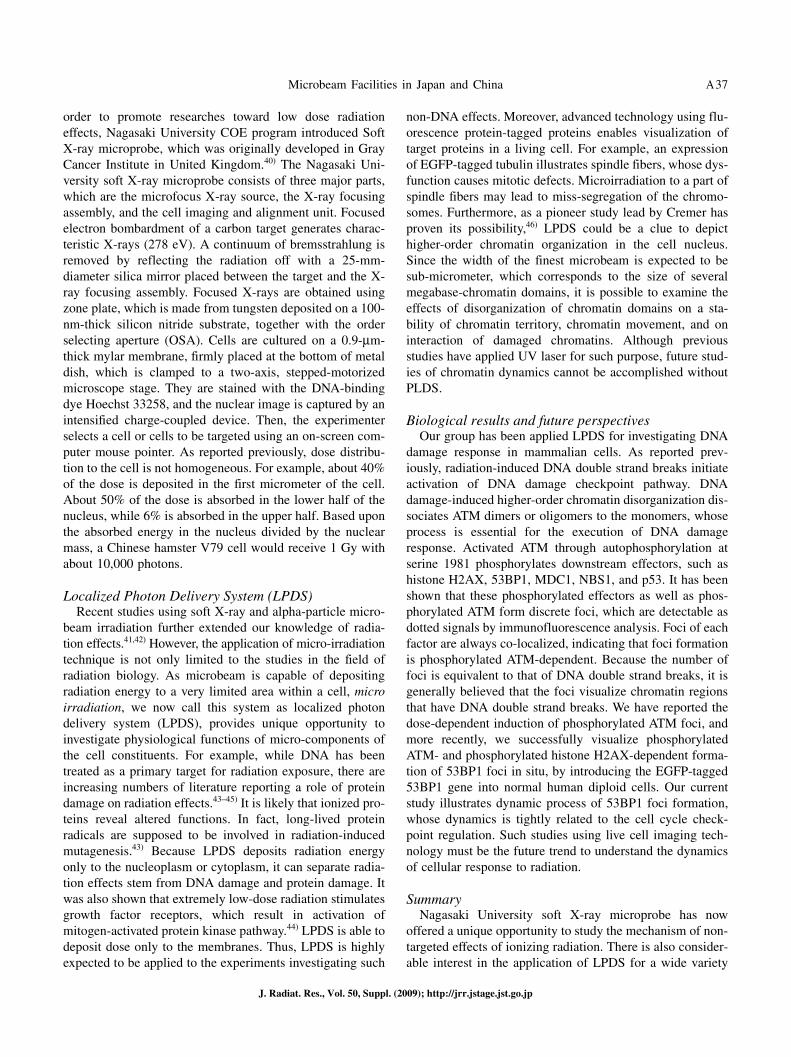
Figure 8 shows the incidence pattern obtained by auto-matic irradiation of the CR-39 track detector to draw the let-ters ‘WERC’. The letters were about 100 μm tall each, and consisted of total 76 points, with 50 counts per point. The letters ‘WERC’ can be recognized clearly, which shows that the automatic irradiation is performed successfully. Tracks distributed randomly around the letters are presumably due to edge scattering at the capillary.
SummaryA system for irradiating single cells with controlled ion
doses has been developed at the W-MAST facility. The col-
limated ion beam delivered vertically is used for the irradi-ation. The system is controlled using a PC and NIM modules to allow sequential cell irradiation. The results of test exper-iments revealed that 93% of the collimated helium ions were mono-energetic and that the beam spot was about 10 μm. Automated irradiation of a CR-39 track detector demon-strated the sequential irradiation successfully. Further deve-lopments for the determination of the beam position at the target position and for observing living cells with the micro-scope are needed for the single cell irradiation.
NAGASAKI UNIVERSITY SOFT X-RAYMICROPROBE
Composition of the systemThere are a couple of microbeam facilities in the world
including those settled in Nagasaki University. Nagasaki University had conducted so called the 21st century Center Of Excellence (COE) program between 2002 and 2007. The title of the program was “International Consortium for Med-ical Care of Hibakusya and Radiation Life Science”, and, in
Fig. 7. Beam size measured using a CR-39 track detector. Bar is a 10 μm-long scale.
Fig. 8. Incidence pattern after automated irradiation of the letters ‘WERC’. Each letter is about 100 μm tall.
Microbeam Facilities in Japan and China A37
J. Radiat. Res., Vol. 50, Suppl. (2009); http://jrr.jstage.jst.go.jp
order to promote researches toward low dose radiation effects, Nagasaki University COE program introduced Soft X-ray microprobe, which was originally developed in Gray Cancer Institute in United Kingdom.40) The Nagasaki Uni-versity soft X-ray microprobe consists of three major parts, which are the microfocus X-ray source, the X-ray focusing assembly, and the cell imaging and alignment unit. Focused electron bombardment of a carbon target generates charac-teristic X-rays (278 eV). A continuum of bremsstrahlung is removed by reflecting the radiation off with a 25-mm-diameter silica mirror placed between the target and the X-ray focusing assembly. Focused X-rays are obtained using zone plate, which is made from tungsten deposited on a 100-nm-thick silicon nitride substrate, together with the order selecting aperture (OSA). Cells are cultured on a 0.9-μm-thick mylar membrane, firmly placed at the bottom of metal dish, which is clamped to a two-axis, stepped-motorized microscope stage. They are stained with the DNA-binding dye Hoechst 33258, and the nuclear image is captured by an intensified charge-coupled device. Then, the experimenter selects a cell or cells to be targeted using an on-screen com-puter mouse pointer. As reported previously, dose distribu-tion to the cell is not homogeneous. For example, about 40% of the dose is deposited in the first micrometer of the cell. About 50% of the dose is absorbed in the lower half of the nucleus, while 6% is absorbed in the upper half. Based upon the absorbed energy in the nucleus divided by the nuclear mass, a Chinese hamster V79 cell would receive 1 Gy with about 10,000 photons.
Localized Photon Delivery System (LPDS)Recent studies using soft X-ray and alpha-particle micro-
beam irradiation further extended our knowledge of radia-tion effects.41,42) However, the application of micro-irradiation technique is not only limited to the studies in the field of radiation biology. As microbeam is capable of depositing radiation energy to a very limited area within a cell, micro irradiation, we now call this system as localized photon delivery system (LPDS), provides unique opportunity to investigate physiological functions of micro-components of the cell constituents. For example, while DNA has been treated as a primary target for radiation exposure, there are increasing numbers of literature reporting a role of protein damage on radiation effects.43–45) It is likely that ionized pro-teins reveal altered functions. In fact, long-lived protein radicals are supposed to be involved in radiation-induced mutagenesis.43) Because LPDS deposits radiation energy only to the nucleoplasm or cytoplasm, it can separate radia-tion effects stem from DNA damage and protein damage. It was also shown that extremely low-dose radiation stimulates growth factor receptors, which result in activation of mitogen-activated protein kinase pathway.44) LPDS is able to deposit dose only to the membranes. Thus, LPDS is highly expected to be applied to the experiments investigating such
non-DNA effects. Moreover, advanced technology using flu-orescence protein-tagged proteins enables visualization of target proteins in a living cell. For example, an expression of EGFP-tagged tubulin illustrates spindle fibers, whose dys-function causes mitotic defects. Microirradiation to a part of spindle fibers may lead to miss-segregation of the chromo-somes. Furthermore, as a pioneer study lead by Cremer has proven its possibility,46) LPDS could be a clue to depict higher-order chromatin organization in the cell nucleus. Since the width of the finest microbeam is expected to be sub-micrometer, which corresponds to the size of several megabase-chromatin domains, it is possible to examine the effects of disorganization of chromatin domains on a sta-bility of chromatin territory, chromatin movement, and on interaction of damaged chromatins. Although previous studies have applied UV laser for such purpose, future stud-ies of chromatin dynamics cannot be accomplished without PLDS.
Biological results and future perspectivesOur group has been applied LPDS for investigating DNA
damage response in mammalian cells. As reported prev-iously, radiation-induced DNA double strand breaks initiate activation of DNA damage checkpoint pathway. DNA damage-induced higher-order chromatin disorganization dis-sociates ATM dimers or oligomers to the monomers, whose process is essential for the execution of DNA damage response. Activated ATM through autophosphorylation at serine 1981 phosphorylates downstream effectors, such as histone H2AX, 53BP1, MDC1, NBS1, and p53. It has been shown that these phosphorylated effectors as well as phos-phorylated ATM form discrete foci, which are detectable as dotted signals by immunofluorescence analysis. Foci of each factor are always co-localized, indicating that foci formation is phosphorylated ATM-dependent. Because the number of foci is equivalent to that of DNA double strand breaks, it is generally believed that the foci visualize chromatin regions that have DNA double strand breaks. We have reported the dose-dependent induction of phosphorylated ATM foci, and more recently, we successfully visualize phosphorylated ATM- and phosphorylated histone H2AX-dependent forma-tion of 53BP1 foci in situ, by introducing the EGFP-tagged 53BP1 gene into normal human diploid cells. Our current study illustrates dynamic process of 53BP1 foci formation, whose dynamics is tightly related to the cell cycle check-point regulation. Such studies using live cell imaging tech-nology must be the future trend to understand the dynamics of cellular response to radiation.
SummaryNagasaki University soft X-ray microprobe has now
offered a unique opportunity to study the mechanism of non-targeted effects of ionizing radiation. There is also consider-able interest in the application of LPDS for a wide variety
Y. Kobayashi et al.A38
J. Radiat. Res., Vol. 50, Suppl. (2009); http://jrr.jstage.jst.go.jp
of research fields. Our collaborative works are expected to contribute to the better understandings of the radiation effects on living organisms.
THE CRIEPI MICROBEAM SOFT X-RAYIRRADIATION SYSTEM
IntroductionToday, many facilities have been developed and planned
microbeam irradiation systems using charged particle radia-tions (see in extended abstracts of 8th International Work-shop: Microbeam probes of Cellular Radiation Response). However, X-ray microprobes, which have been developed and operated constantly, were only at the Gray Cancer Ins-titute (UK)40,47) and at the Photon Factory utilizing SR X-rays.37,48) Microbeam soft X-ray irradiation system at Central Research Institute of Electric Power Industry (CRIEPI), Tokyo, Japan, has been developed in March, 2007 to inves-tigate cellular response to low dose radiation and non-target-ed effects, such as radiation-induced bystander responses, adaptive responses and genomic instability. Our system is characterized by (1) tabletop (2) X-ray focusing system using Fresnel zone plate (FZP), and (3) on-line confocal laser microscope.
The X-ray source and the focusing assemblyFollowing the Gray Cancer Institute ultrasoft X-ray
microprobe,40,47) Fresnel zone plate (FZP) is used to focus characteristic X-ray generated by the electron bombardment of a target. The electron gun is OME-0055LBW (Omega-tron) with lanthanum hexaboride (LaB6) cathode, which can generate a high-brightness focused electron beam, and is operated at voltages up to –30 kV relative to the target (Fig. 9C). The electron beam is focused with electromagnetic lens onto the surface of the target made of aluminum. Rotary pumps, turbo molecular pumps and vacuum gauges are set to the electron gun chamber and the target chamber inde-pendently. The electron gun is connected with the target chamber with a gate valve. To keep the LaB6 filament in a good condition, pressure in the electron gun chamber and the target chamber is always kept at 10–7–10–8 Torr.
Characteristic K-shell X-ray of aluminum (1.49 keV) is generated by the focused electron bombardment of an alu-minum target (Fig. 9D). Hereafter, “soft X-rays” will be used to denote 1.49 keV X-rays. The bremsstrahlung X-rays having higher energy, which are also generated together with characteristic radiation, are removed by reflecting the graz-ing incidence mirror. This mirror is 20 mm × 10 mm made of Au (Fig. 9E). The incident angle is 1.5°. The vacuum window is made of 0.3 mm × 0.3 mm silicon nitride, which is 150 nm thick (Fig. 9F). The FZP is 150 μm in diameter, designed and manufactured by NTT-AT Nanofabrication (Fig. 9G). Exposure period is controlled using the shutter (Fig. 9H). The order selecting aperture (OSA) is used to
select first-order diffracted soft X-ray by blocking unwanted zero and higher-order X-rays. The OSA consists of the pin-hole, 30 μm in diameter (Fig. 9I). From the vacuum window to the OSA, helium gas is continuously blown to minimize attenuation of the soft X-ray.
The Cell imaging and irradiationAutostage, cell irradiation dish and irradiation software
are same as the synchrotron X-ray microbeam irradiation system at the Photon Factory (PF), High Energy Accelerator Research Organization (KEK, Ibaraki, Japan).37,48) Cells are plated on the 1.5 μm-thick Mylar film based cell irradiation dishes (34 mm in diameter, Fig. 10A).37) We have developed custom-made stage top incubator (Tokai Hit, Shizuoka, Japan) that accommodate cell irradiation dish to enable real-time live cell analysis (Fig. 10B).
High resolution cooled CCD camera (ORCA-ER, Hamamatsu Photonics) is combined with irradiation system. To irradiate cells, the beam position is detected using a scin-tillator and records the coordinates of the center of soft X-ray microbeam. Cell nuclei are stained with Hoechst 33258 at a concentration of 1 μM for 30 min before irradiation. After twice wash with PBS, cells are incubated in a fresh medium for the irradiation. The positions of cell nuclei are determined by the fluorescent image obtained using the CCD camera. The position of targets and exposure period are memorized in the irradiation software. For immunofluo-rescent study, confocal laser scanning microscope (FV300, Olympus, Tokyo, Japan) is also combined with irradiation system.
Characteristics of soft X-ray microbeamThe measurement of energy spectrum indicated that
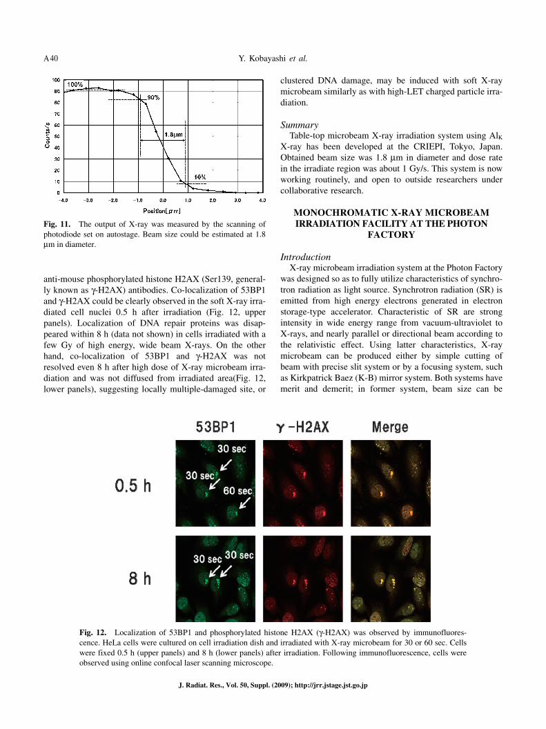
focused 1.49 keV of Al-Kα X-ray can be acquired at the sample position through the OSA (data not shown). Beam size was measured by knife-edge scanning and observed beam size was 1.8 μm in diameter (Fig. 11). Dose rate in the irradiated region was about 1 Gy/s under the usual operating condition.
Detection of DNA damage induced by soft X-ray micro-beam irradiation
The induction of complex clustered DNA damage, having multiple DNA lesions within a few helical turns, has been considered as the cause of efficient cell killing of high LET charged particle radiations. To examine a possibility of the induction of complex clustered DNA damage induced by high dose of focused soft X-ray microbeam irradiation, human cervical carcinoma HeLa cells were irradiated with X-ray microbeam for 30 or 60 sec (about 30 or 60 Gy within irradiated region). Cells were fixed with cold methanol and rinsed with cold acetone 0.5 or 8 h after irradiation. DNA lesions induced by soft X-ray microbeam were visualized by immunofluorescence staining with anti-rabbit 53BP1 and
Microbeam Facilities in Japan and China A39
J. Radiat. Res., Vol. 50, Suppl. (2009); http://jrr.jstage.jst.go.jp
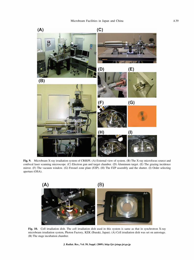
Fig. 9. Microbeam X-ray irradiation system of CRIEPI. (A) External view of system. (B) The X-ray microfocus source and confocal laser scanning microscope. (C) Electron gun and target chamber. (D) Aluminum target. (E) The grazing incidence mirror. (F) The vacuum window. (G) Fresnel zone plate (FZP). (H) The FZP assembly and the shutter. (I) Order selecting aperture (OSA).
Fig. 10. Cell irradiation dish. The cell irradiation dish used in this system is same as that in synchrotron X-ray microbeam irradiation system, Photon Factory, KEK (Ibaraki, Japan). (A) Cell irradiation dish was set on autostage. (B) The stage incubation chamber.
Y. Kobayashi et al.A40
J. Radiat. Res., Vol. 50, Suppl. (2009); http://jrr.jstage.jst.go.jp
anti-mouse phosphorylated histone H2AX (Ser139, general-ly known as γ-H2AX) antibodies. Co-localization of 53BP1 and γ-H2AX could be clearly observed in the soft X-ray irra-diated cell nuclei 0.5 h after irradiation (Fig. 12, upper panels). Localization of DNA repair proteins was disap-peared within 8 h (data not shown) in cells irradiated with a few Gy of high energy, wide beam X-rays. On the other hand, co-localization of 53BP1 and γ-H2AX was not resolved even 8 h after high dose of X-ray microbeam irra-diation and was not diffused from irradiated area(Fig. 12, lower panels), suggesting locally multiple-damaged site, or
clustered DNA damage, may be induced with soft X-ray microbeam similarly as with high-LET charged particle irra-diation.
SummaryTable-top microbeam X-ray irradiation system using AlK
X-ray has been developed at the CRIEPI, Tokyo, Japan. Obtained beam size was 1.8 μm in diameter and dose rate in the irradiate region was about 1 Gy/s. This system is now working routinely, and open to outside researchers under collaborative research.
MONOCHROMATIC X-RAY MICROBEAMIRRADIATION FACILITY AT THE PHOTON
FACTORY
IntroductionX-ray microbeam irradiation system at the Photon Factory
was designed so as to fully utilize characteristics of synchro-tron radiation as light source. Synchrotron radiation (SR) is emitted from high energy electrons generated in electron storage-type accelerator. Characteristic of SR are strong intensity in wide energy range from vacuum-ultraviolet to X-rays, and nearly parallel or directional beam according to the relativistic effect. Using latter characteristics, X-ray microbeam can be produced either by simple cutting of beam with precise slit system or by a focusing system, such as Kirkpatrick Baez (K-B) mirror system. Both systems have merit and demerit; in former system, beam size can be
Fig. 11. The output of X-ray was measured by the scanning of photodiode set on autostage. Beam size could be estimated at 1.8 μm in diameter.
Fig. 12. Localization of 53BP1 and phosphorylated histone H2AX (γ-H2AX) was observed by immunofluores-cence. HeLa cells were cultured on cell irradiation dish and irradiated with X-ray microbeam for 30 or 60 sec. Cells were fixed 0.5 h (upper panels) and 8 h (lower panels) after irradiation. Following immunofluorescence, cells were observed using online confocal laser scanning microscope.
Microbeam Facilities in Japan and China A41
J. Radiat. Res., Vol. 50, Suppl. (2009); http://jrr.jstage.jst.go.jp
changed arbitrarily above 5 μm square with constant inten-sity, in the latter, more intense beam (higher photon density) is available in smaller beam while change of beam size is not so easy. Considering these points, we decided to employ a precise slit system to obtain X-ray microbeam. We have developed three type of microbeam irradiation system. All the developed systems have been installed at BL-27B in the Photon Factory, Institute of Materials Structure Science, High Energy Accelerator Research Organization (KEK) in Tsukuba, Japan. Experimental stations at BL-27 are situated in the biological sample preparation area, where incubators and other equipments to grow and handle mammalian cells are available.
Energy-fixed (5.35 keV) X-ray microbeam irradiation apparatus
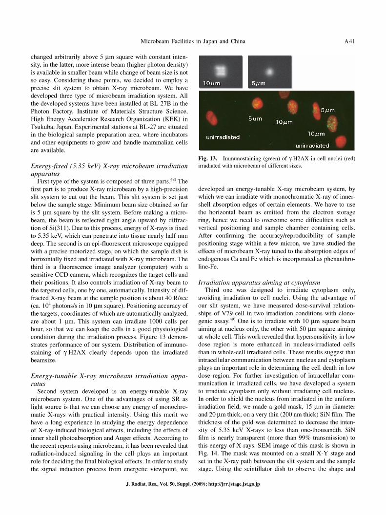
First type of the system is composed of three parts.48) The first part is to produce X-ray microbeam by a high-precision slit system to cut out the beam. This slit system is set just below the sample stage. Minimum beam size obtained so far is 5 μm square by the slit system. Before making a micro-beam, the beam is reflected right angle upward by diffrac-tion of Si(311). Due to this process, energy of X-rays is fixed to 5.35 keV, which can penetrate into tissue nearly half mm deep. The second is an epi-fluorescent microscope equipped with a precise motorized stage, on which the sample dish is horizontally fixed and irradiated with X-ray microbeam. The third is a fluorescence image analyzer (computer) with a sensitive CCD camera, which recognizes the target cells and their positions. It also controls irradiation of X-ray beam to the targeted cells, one by one, automatically. Intensity of dif-fracted X-ray beam at the sample position is about 40 R/sec (ca. 104 photons/s in 10 μm square). Positioning accuracy of the targets, coordinates of which are automatically analyzed, are about 1 μm. This system can irradiate 1000 cells per hour, so that we can keep the cells in a good physiological condition during the irradiation process. Figure 13 demon-strates performance of our system. Distribution of immuno-staining of γ-H2AX clearly depends upon the irradiated beamsize.
Energy-tunable X-ray microbeam irradiation appa-ratus
Second system developed is an energy-tunable X-ray microbeam system. One of the advantages of using SR as light source is that we can choose any energy of monochro-matic X-rays with practical intensity. Using this merit we have a long experience in studying the energy dependence of X-ray-induced biological effects, including the effects of inner shell photoabsorption and Auger effects. According to the recent reports using microbeam, it has been revealed that radiation-induced signaling in the cell plays an important role for deciding the final biological effects. In order to study the signal induction process from energetic viewpoint, we
developed an energy-tunable X-ray microbeam system, by which we can irradiate with monochromatic X-ray of inner-shell absorption edges of certain elements. We have to use the horizontal beam as emitted from the electron storage ring, hence we need to overcome some difficulties such as vertical positioning and sample chamber containing cells. After confirming the accuracy/reproducibility of sample positioning stage within a few micron, we have studied the effects of microbeam X-ray tuned to the absorption edges of endogenous Ca and Fe which is incorporated as phenanthro-line-Fe.
Irradiation apparatus aiming at cytoplasmThird one was designed to irradiate cytoplasm only,
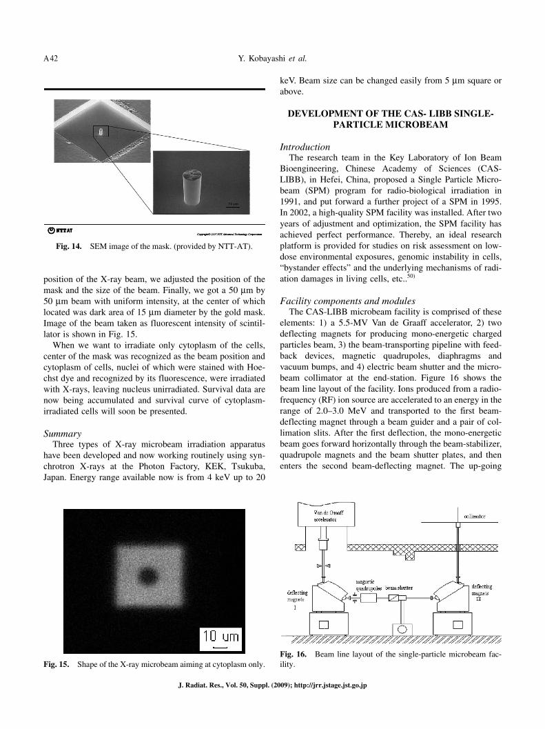
avoiding irradiation to cell nuclei. Using the advantage of our slit system, we have measured dose-survival relation-ships of V79 cell in two irradiation conditions with clono-genic assay.49) One is to irradiate with 10 μm square beam aiming at nucleus only, the other with 50 μm square aiming at whole cell. This work revealed that hypersensitivity in low dose region is more enhanced in nucleus-irradiated cells than in whole-cell irradiated cells. These results suggest that intracellular communication between nucleus and cytoplasm plays an important role in determining the cell death in low dose region. For further investigation of intracellular com-munication in irradiated cells, we have developed a system to irradiate cytoplasm only without irradiating cell nucleus. In order to shield the nucleus from irradiated in the uniform irradiation field, we made a gold mask, 15 μm in diameter and 20 μm thick, on a very thin (200 nm thick) SiN film. The thickness of the gold was determined to decrease the inten-sity of 5.35 keV X-rays to less than one-thousandth. SiN film is nearly transparent (more than 99% transmission) to this energy of X-rays. SEM image of this mask is shown in Fig. 14. The mask was mounted on a small X-Y stage and set in the X-ray path between the slit system and the sample stage. Using the scintillator dish to observe the shape and
Fig. 13. Immunostaining (green) of γ-H2AX in cell nuclei (red) irradiated with microbeam of different sizes.
Y. Kobayashi et al.A42
J. Radiat. Res., Vol. 50, Suppl. (2009); http://jrr.jstage.jst.go.jp
position of the X-ray beam, we adjusted the position of the mask and the size of the beam. Finally, we got a 50 μm by 50 μm beam with uniform intensity, at the center of which located was dark area of 15 μm diameter by the gold mask. Image of the beam taken as fluorescent intensity of scintil-lator is shown in Fig. 15.
When we want to irradiate only cytoplasm of the cells, center of the mask was recognized as the beam position and cytoplasm of cells, nuclei of which were stained with Hoe-chst dye and recognized by its fluorescence, were irradiated with X-rays, leaving nucleus unirradiated. Survival data are now being accumulated and survival curve of cytoplasm-irradiated cells will soon be presented.
SummaryThree types of X-ray microbeam irradiation apparatus
have been developed and now working routinely using syn-chrotron X-rays at the Photon Factory, KEK, Tsukuba, Japan. Energy range available now is from 4 keV up to 20
keV. Beam size can be changed easily from 5 μm square or above.
DEVELOPMENT OF THE CAS- LIBB SINGLE-PARTICLE MICROBEAM
IntroductionThe research team in the Key Laboratory of Ion Beam
Bioengineering, Chinese Academy of Sciences (CAS-LIBB), in Hefei, China, proposed a Single Particle Micro-beam (SPM) program for radio-biological irradiation in 1991, and put forward a further project of a SPM in 1995. In 2002, a high-quality SPM facility was installed. After two years of adjustment and optimization, the SPM facility has achieved perfect performance. Thereby, an ideal research platform is provided for studies on risk assessment on low-dose environmental exposures, genomic instability in cells, “bystander effects” and the underlying mechanisms of radi-ation damages in living cells, etc..50)
Facility components and modulesThe CAS-LIBB microbeam facility is comprised of these
elements: 1) a 5.5-MV Van de Graaff accelerator, 2) two deflecting magnets for producing mono-energetic charged particles beam, 3) the beam-transporting pipeline with feed-back devices, magnetic quadrupoles, diaphragms and vacuum bumps, and 4) electric beam shutter and the micro-beam collimator at the end-station. Figure 16 shows the beam line layout of the facility. Ions produced from a radio-frequency (RF) ion source are accelerated to an energy in the range of 2.0–3.0 MeV and transported to the first beam-deflecting magnet through a beam guider and a pair of col-limation slits. After the first deflection, the mono-energetic beam goes forward horizontally through the beam-stabilizer, quadrupole magnets and the beam shutter plates, and then enters the second beam-deflecting magnet. The up-going
Fig. 14. SEM image of the mask. (provided by NTT-AT).
Fig. 15. Shape of the X-ray microbeam aiming at cytoplasm only.Fig. 16. Beam line layout of the single-particle microbeam fac-ility.
Microbeam Facilities in Japan and China A43
J. Radiat. Res., Vol. 50, Suppl. (2009); http://jrr.jstage.jst.go.jp
beam deflected by the second magnet travels vertically through another collimation slits and finally enters the microbeam terminal room.1,2,51–53)
It should be possible for the SPM facility to irradiate a pre-selected target with the accuracy down to several microns or even less to realize fully its potential. Two suc-cessful methods are available for forming microbeam: colli-mation and focusing. For low-energy ion irradiation of sample cells grown outside vacuum, employment of a colli-mated microbeam is preferred owing to simplicities of the setup and its operation.1,2,36,51,52,54–57) Experimental results have demonstrated that a μm-diameter collimated micro-beam has a sufficient resolution for cellular or sub-cellular irradiation.58–60)
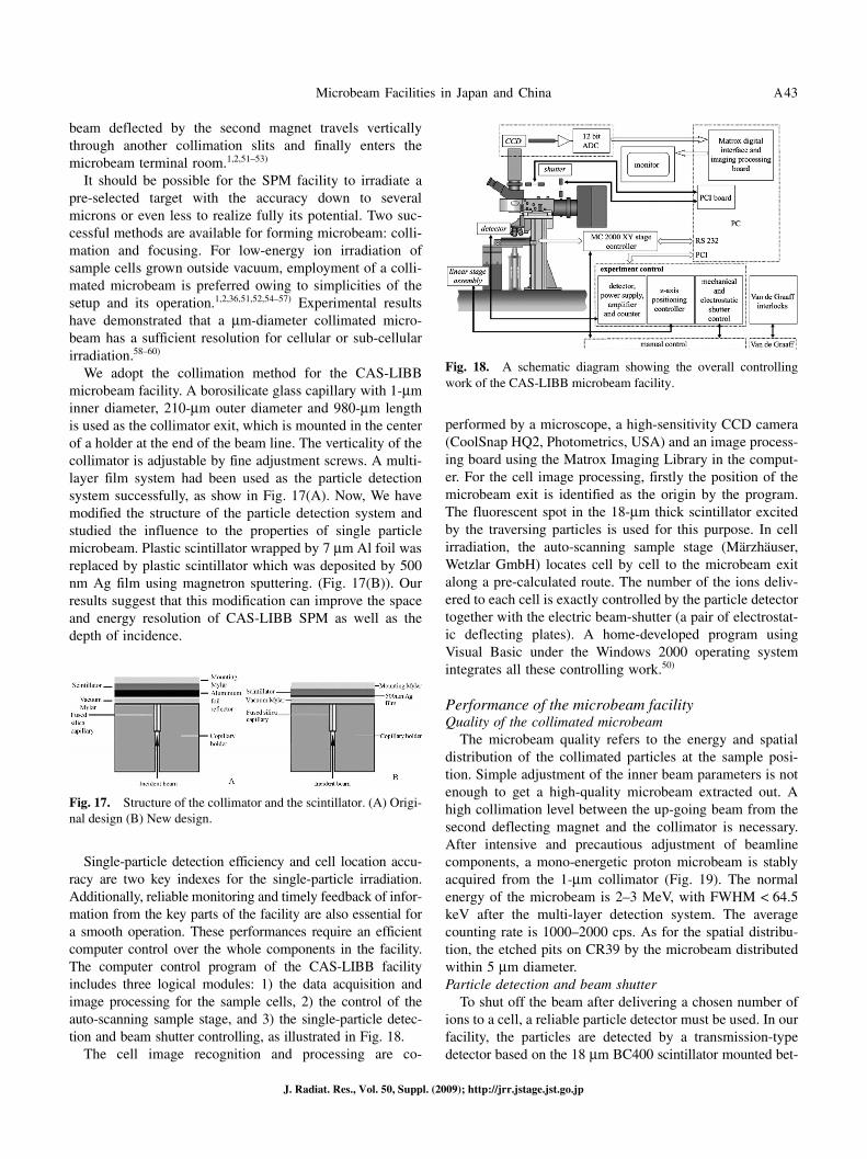
We adopt the collimation method for the CAS-LIBB microbeam facility. A borosilicate glass capillary with 1-μm inner diameter, 210-μm outer diameter and 980-μm length is used as the collimator exit, which is mounted in the center of a holder at the end of the beam line. The verticality of the collimator is adjustable by fine adjustment screws. A multi-layer film system had been used as the particle detection system successfully, as show in Fig. 17(A). Now, We have modified the structure of the particle detection system and studied the influence to the properties of single particle microbeam. Plastic scintillator wrapped by 7 μm Al foil was replaced by plastic scintillator which was deposited by 500 nm Ag film using magnetron sputtering. (Fig. 17(B)). Our results suggest that this modification can improve the space and energy resolution of CAS-LIBB SPM as well as the depth of incidence.
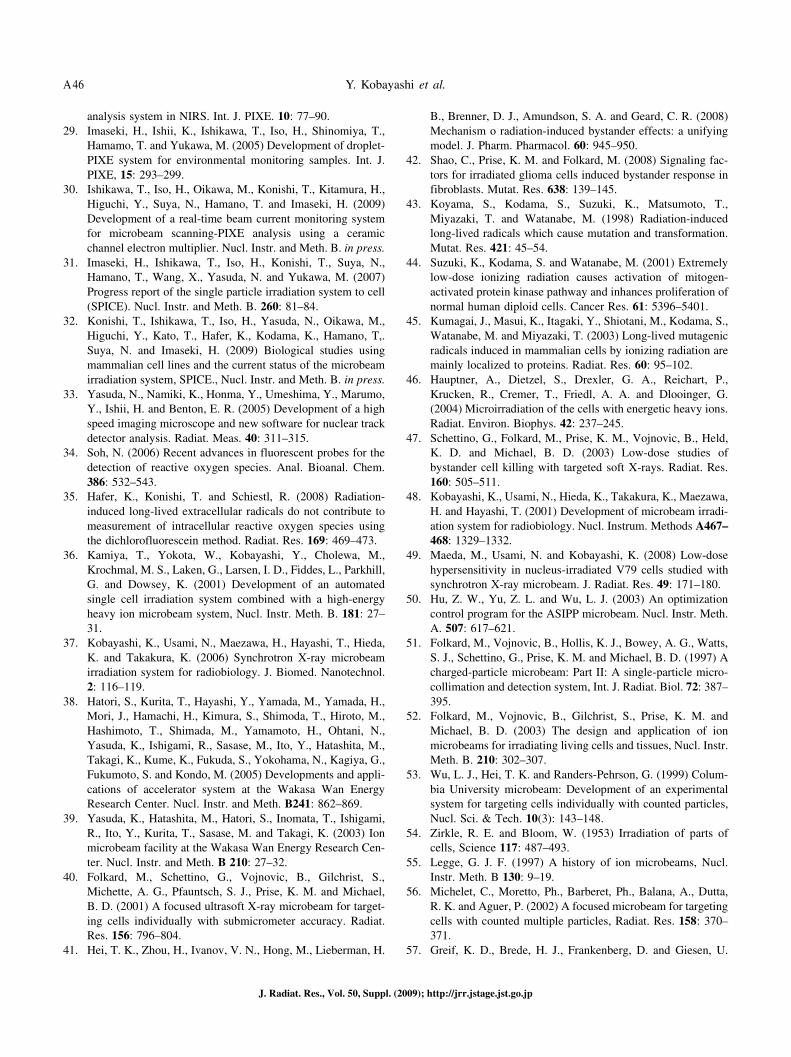
Single-particle detection efficiency and cell location accu-racy are two key indexes for the single-particle irradiation. Additionally, reliable monitoring and timely feedback of infor-mation from the key parts of the facility are also essential for a smooth operation. These performances require an efficient computer control over the whole components in the facility. The computer control program of the CAS-LIBB facility includes three logical modules: 1) the data acquisition and image processing for the sample cells, 2) the control of the auto-scanning sample stage, and 3) the single-particle detec-tion and beam shutter controlling, as illustrated in Fig. 18.
The cell image recognition and processing are co-
performed by a microscope, a high-sensitivity CCD camera (CoolSnap HQ2, Photometrics, USA) and an image process-ing board using the Matrox Imaging Library in the comput-er. For the cell image processing, firstly the position of the microbeam exit is identified as the origin by the program. The fluorescent spot in the 18-μm thick scintillator excited by the traversing particles is used for this purpose. In cell irradiation, the auto-scanning sample stage (Märzhäuser, Wetzlar GmbH) locates cell by cell to the microbeam exit along a pre-calculated route. The number of the ions deliv-ered to each cell is exactly controlled by the particle detector together with the electric beam-shutter (a pair of electrostat-ic deflecting plates). A home-developed program using Visual Basic under the Windows 2000 operating system integrates all these controlling work.50)
Performance of the microbeam facilityQuality of the collimated microbeam
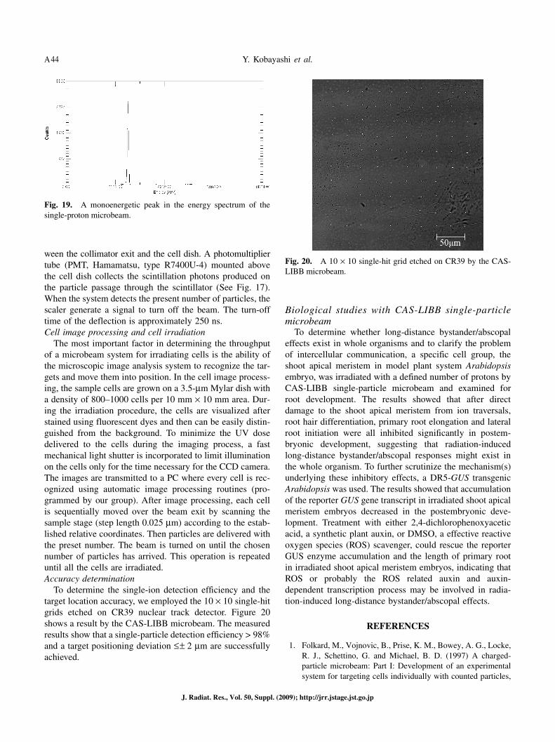
The microbeam quality refers to the energy and spatial distribution of the collimated particles at the sample posi-tion. Simple adjustment of the inner beam parameters is not enough to get a high-quality microbeam extracted out. A high collimation level between the up-going beam from the second deflecting magnet and the collimator is necessary. After intensive and precautious adjustment of beamline components, a mono-energetic proton microbeam is stably acquired from the 1-μm collimator (Fig. 19). The normal energy of the microbeam is 2–3 MeV, with FWHM < 64.5 keV after the multi-layer detection system. The average counting rate is 1000–2000 cps. As for the spatial distribu-tion, the etched pits on CR39 by the microbeam distributed within 5 μm diameter.Particle detection and beam shutter
To shut off the beam after delivering a chosen number of ions to a cell, a reliable particle detector must be used. In our facility, the particles are detected by a transmission-type detector based on the 18 μm BC400 scintillator mounted bet-
Fig. 17. Structure of the collimator and the scintillator. (A) Origi-nal design (B) New design.
Fig. 18. A schematic diagram showing the overall controlling work of the CAS-LIBB microbeam facility.
Y. Kobayashi et al.A44
J. Radiat. Res., Vol. 50, Suppl. (2009); http://jrr.jstage.jst.go.jp
ween the collimator exit and the cell dish. A photomultiplier tube (PMT, Hamamatsu, type R7400U-4) mounted above the cell dish collects the scintillation photons produced on the particle passage through the scintillator (See Fig. 17). When the system detects the present number of particles, the scaler generate a signal to turn off the beam. The turn-off time of the deflection is approximately 250 ns.Cell image processing and cell irradiation
The most important factor in determining the throughput of a microbeam system for irradiating cells is the ability of the microscopic image analysis system to recognize the tar-gets and move them into position. In the cell image process-ing, the sample cells are grown on a 3.5-μm Mylar dish with a density of 800–1000 cells per 10 mm × 10 mm area. Dur-ing the irradiation procedure, the cells are visualized after stained using fluorescent dyes and then can be easily distin-guished from the background. To minimize the UV dose delivered to the cells during the imaging process, a fast mechanical light shutter is incorporated to limit illumination on the cells only for the time necessary for the CCD camera. The images are transmitted to a PC where every cell is rec-ognized using automatic image processing routines (pro-grammed by our group). After image processing, each cell is sequentially moved over the beam exit by scanning the sample stage (step length 0.025 μm) according to the estab-lished relative coordinates. Then particles are delivered with the preset number. The beam is turned on until the chosen number of particles has arrived. This operation is repeated until all the cells are irradiated.Accuracy determination
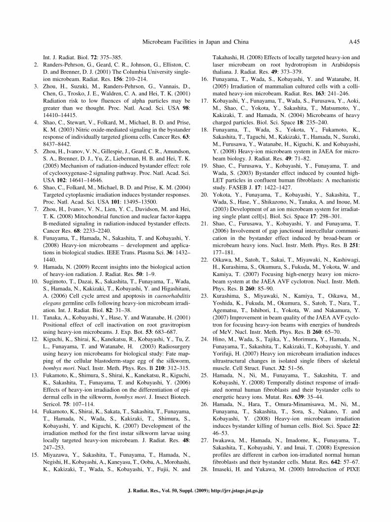
To determine the single-ion detection efficiency and the target location accuracy, we employed the 10 × 10 single-hit grids etched on CR39 nuclear track detector. Figure 20 shows a result by the CAS-LIBB microbeam. The measured results show that a single-particle detection efficiency > 98% and a target positioning deviation ≤ ± 2 μm are successfully achieved.
Biological studies with CAS-LIBB single-particle microbeam
To determine whether long-distance bystander/abscopal effects exist in whole organisms and to clarify the problem of intercellular communication, a specific cell group, the shoot apical meristem in model plant system Arabidopsis embryo, was irradiated with a defined number of protons by CAS-LIBB single-particle microbeam and examined for root development. The results showed that after direct damage to the shoot apical meristem from ion traversals, root hair differentiation, primary root elongation and lateral root initiation were all inhibited significantly in postem-bryonic development, suggesting that radiation-induced long-distance bystander/abscopal responses might exist in the whole organism. To further scrutinize the mechanism(s) underlying these inhibitory effects, a DR5-GUS transgenic Arabidopsis was used. The results showed that accumulation of the reporter GUS gene transcript in irradiated shoot apical meristem embryos decreased in the postembryonic deve-lopment. Treatment with either 2,4-dichlorophenoxyacetic acid, a synthetic plant auxin, or DMSO, a effective reactive oxygen species (ROS) scavenger, could rescue the reporter GUS enzyme accumulation and the length of primary root in irradiated shoot apical meristem embryos, indicating that ROS or probably the ROS related auxin and auxin-dependent transcription process may be involved in radia-tion-induced long-distance bystander/abscopal effects.
REFERENCES
1. Folkard, M., Vojnovic, B., Prise, K. M., Bowey, A. G., Locke, R. J., Schettino, G. and Michael, B. D. (1997) A charged-particle microbeam: Part I: Development of an experimental system for targeting cells individually with counted particles,
Fig. 19. A monoenergetic peak in the energy spectrum of the single-proton microbeam.
Fig. 20. A 10 × 10 single-hit grid etched on CR39 by the CAS-LIBB microbeam.
Microbeam Facilities in Japan and China A45
J. Radiat. Res., Vol. 50, Suppl. (2009); http://jrr.jstage.jst.go.jp
Int. J. Radiat. Biol. 72: 375–385.2. Randers-Pehrson, G., Geard, C. R., Johnson, G., Elliston, C.
D. and Brenner, D. J. (2001) The Columbia University single-ion microbeam. Radiat. Res. 156: 210–214.
3. Zhou, H., Suzuki, M., Randers-Pehrson, G., Vannais, D., Chen, G., Trosko, J. E., Waldren, C. A. and Hei, T. K. (2001) Radiation risk to low fluences of alpha particles may be greater than we thought. Proc. Natl. Acad. Sci. USA 98: 14410–14415.
4. Shao, C., Stewart, V., Folkard, M., Michael, B. D. and Prise, K. M. (2003) Nitric oxide-mediated signaling in the bystander response of individually targeted glioma cells. Cancer Res. 63: 8437–8442.
5. Zhou, H., Ivanov, V. N., Gillespie, J., Geard, C. R., Amundson, S. A., Brenner, D. J., Yu, Z., Lieberman, H. B. and Hei, T. K. (2005) Mechanism of radiation-induced bystander effect: role of cyclooxygenase-2 signaling pathway. Proc. Natl. Acad. Sci. USA 102: 14641–14646.
6. Shao, C., Folkard, M., Michael, B. D. and Prise, K. M. (2004) Targeted cytoplasmic irradiation induces bystander responses. Proc. Natl. Acad. Sci. USA 101: 13495–13500.
7. Zhou, H., Ivanov, V. N., Lien, Y. C., Davidson, M. and Hei, T. K. (2008) Mitochondrial function and nuclear factor-kappa B-mediated signaling in radiation-induced bystander effects. Cancer Res. 68: 2233–2240.
8. Funayama, T., Hamada, N., Sakashita, T. and Kobayashi, Y. (2008) Heavy-ion microbeams – development and applica-tions in biological studies. IEEE Trans. Plasma Sci. 36: 1432–1440.
9. Hamada, N. (2009) Recent insights into the biological action of heavy-ion radiation. J. Radiat. Res. 50: 1–9.
10. Sugimoto, T., Dazai, K., Sakashita, T., Funayama, T., Wada, S., Hamada, N., Kakizaki, T., Kobayashi, Y. and Higashitani, A. (2006) Cell cycle arrest and apoptosis in caenorhabditis elegans germline cells following heavy-ion microbeam irradi-ation. Int. J. Radiat. Biol. 82: 31–38.
11. Tanaka, A., Kobayashi, Y., Hase, Y. and Watanabe, H. (2001) Positional effect of cell inactivation on root gravitropism using heavy-ion microbeams. J. Exp. Bot. 53: 683–687.
12. Kiguchi, K., Shirai, K., Kanekatsu, R., Kobayashi, Y., Tu, Z. L., Funayama, T. and Watanabe, H. (2003) Radiosurgery using heavy ion microbeams for biological study: Fate map-ping of the cellular blastoderm-stage egg of the silkworm, bombyx mori. Nucl. Instr. Meth. Phys. Res. B 210: 312–315.
13. Fukamoto, K., Shimura, S., Shirai, K., Kanekatsu, R., Kiguchi, K., Sakashita, T., Funayama, T. and Kobayashi, Y. (2006) Effects of heavy-ion irradiadion on the differentiation of epi-dermal cells in the silkworm, bombyx mori. J. Insect Biotech. Sericol. 75: 107–114.
14. Fukamoto, K., Shirai, K., Sakata, T., Sakashita, T., Funayama, T., Hamada, N., Wada, S., Kakizaki, T., Shimura, S., Kobayashi, Y. and Kiguchi, K. (2007) Development of the irradiation method for the first instar silkworm larvae using locally targeted heavy-ion microbeam. J. Radiat. Res. 48: 247–253.
15. Miyazawa, Y., Sakashita, T., Funayama, T., Hamada, N., Negishi, H., Kobayashi, A., Kaneyasu, T., Ooba, A., Morohashi, K., Kakizaki, T., Wada, S., Kobayashi, Y., Fujii, N. and
Takahashi, H. (2008) Effects of locally targeted heavy-ion and laser microbeam on root hydrotropism in Arabidopsis thaliana. J. Radiat. Res. 49: 373–379.
16. Funayama, T., Wada, S., Kobayashi, Y. and Watanabe, H. (2005) Irradiation of mammalian cultured cells with a colli-mated heavy-ion microbeam. Radiat. Res. 163: 241–246.
17. Kobayashi, Y., Funayama, T., Wada, S., Furusawa, Y., Aoki, M., Shao, C., Yokota, Y., Sakashita, T., Matsumoto, Y., Kakizaki, T. and Hamada, N. (2004) Microbeams of heavy charged particles. Biol. Sci. Space 18: 235–240.
18. Funayama, T., Wada, S., Yokota, Y., Fukamoto, K., Sakashita, T., Taguchi, M., Kakizaki, T., Hamada, N., Suzuki, M., Furusawa, Y., Watanabe, H., Kiguchi, K. and Kobayashi, Y. (2008) Heavy-ion microbeam system in JAEA for micro-beam biology. J. Radiat. Res. 49: 71–82.
19. Shao, C., Furusawa, Y., Kobayashi, Y., Funayama, T. and Wada, S. (2003) Bystander effect induced by counted high-LET particles in confluent human fibroblasts: A mechanistic study. FASEB J. 17: 1422–1427.
20. Yokota, Y., Funayama, T., Kobayashi, Y., Sakashita, T., Wada, S., Hase, Y., Shikazono, N., Tanaka, A. and Inoue, M. (2003) Development of an ion microbeam system for irradiat-ing single plant cell[s]. Biol. Sci. Space 17: 298–301.
21. Shao, C., Furusawa, Y., Kobayashi, Y. and Funayama, T. (2006) Involvement of gap junctional intercellular communi-cation in the bystander effect induced by broad-beam or microbeam heavy ions. Nucl. Instr. Meth. Phys. Res. B 251: 177–181.
22. Oikawa, M., Satoh, T., Sakai, T., Miyawaki, N., Kashiwagi, H., Kurashima, S., Okumura, S., Fukuda, M., Yokota, W. and Kamiya, T. (2007) Focusing high-energy heavy ion micro-beam system at the JAEA AVF cyclotron. Nucl. Instr. Meth. Phys. Res. B 260: 85–90.
23. Kurashima, S., Miyawaki, N., Kamiya, T., Oikawa, M., Yoshida, K., Fukuda, M., Okumura, S., Satoh, T., Nara, T., Agematsu, T., Ishibori, I., Yokota, W. and Nakamura, Y. (2007) Improvement in beam quality of the JAEA AVF cyclo-tron for focusing heavy-ion beams with energies of hundreds of MeV. Nucl. Instr. Meth. Phys. Res. B 260: 65–70.
24. Hino, M., Wada, S., Tajika, Y., Morimura, Y., Hamada, N., Funayama, T., Sakashita, T., Kakizaki, T., Kobayashi, Y. and Yorifuji, H. (2007) Heavy ion microbeam irradiation induces ultrastructural changes in isolated single fibers of skeletal muscle. Cell Struct. Funct. 32: 51–56.
25. Hamada, N., Ni, M., Funayama, T., Sakashita, T. and Kobayashi, Y. (2008) Temporally distinct response of irradi-ated normal human fibroblasts and their bystander cells to energetic heavy ions. Mutat. Res. 639: 35–44.
26. Hamada, N., Hara, T., Omura-Minamisawa, M., Ni, M., Funayama, T., Sakashita, T., Sora, S., Nakano, T. and Kobayashi, Y. (2008) Heavy-ion microbeam irradiation induces bystander killing of human cells. Biol. Sci. Space 22: 46–53.
27. Iwakawa, M., Hamada, N., Imadome, K., Funayama, T., Sakashita, T., Kobayashi, Y. and Imai, T. (2008) Expression profiles are different in carbon ion-irradiated normal human fibroblasts and their bystander cells. Mutat. Res. 642: 57–67.
28. Imaseki, H. and Yukawa, M. (2000) Introduction of PIXE
Y. Kobayashi et al.A46
J. Radiat. Res., Vol. 50, Suppl. (2009); http://jrr.jstage.jst.go.jp
analysis system in NIRS. Int. J. PIXE. 10: 77–90.29. Imaseki, H., Ishii, K., Ishikawa, T., Iso, H., Shinomiya, T.,
Hamamo, T. and Yukawa, M. (2005) Development of droplet-PIXE system for environmental monitoring samples. Int. J. PIXE, 15: 293–299.
30. Ishikawa, T., Iso, H., Oikawa, M., Konishi, T., Kitamura, H., Higuchi, Y., Suya, N., Hamano, T. and Imaseki, H. (2009) Development of a real-time beam current monitoring system for microbeam scanning-PIXE analysis using a ceramic channel electron multiplier. Nucl. Instr. and Meth. B. in press.
31. Imaseki, H., Ishikawa, T., Iso, H., Konishi, T., Suya, N., Hamano, T., Wang, X., Yasuda, N. and Yukawa, M. (2007) Progress report of the single particle irradiation system to cell (SPICE). Nucl. Instr. and Meth. B. 260: 81–84.
32. Konishi, T., Ishikawa, T., Iso, H., Yasuda, N., Oikawa, M., Higuchi, Y., Kato, T., Hafer, K., Kodama, K., Hamano, T,. Suya, N. and Imaseki, H. (2009) Biological studies using mammalian cell lines and the current status of the microbeam irradiation system, SPICE., Nucl. Instr. and Meth. B. in press.
33. Yasuda, N., Namiki, K., Honma, Y., Umeshima, Y., Marumo, Y., Ishii, H. and Benton, E. R. (2005) Development of a high speed imaging microscope and new software for nuclear track detector analysis. Radiat. Meas. 40: 311–315.
34. Soh, N. (2006) Recent advances in fluorescent probes for the detection of reactive oxygen species. Anal. Bioanal. Chem. 386: 532–543.
35. Hafer, K., Konishi, T. and Schiestl, R. (2008) Radiation-induced long-lived extracellular radicals do not contribute to measurement of intracellular reactive oxygen species using the dichlorofluorescein method. Radiat. Res. 169: 469–473.
36. Kamiya, T., Yokota, W., Kobayashi, Y., Cholewa, M., Krochmal, M. S., Laken, G., Larsen, I. D., Fiddes, L., Parkhill, G. and Dowsey, K. (2001) Development of an automated single cell irradiation system combined with a high-energy heavy ion microbeam system, Nucl. Instr. Meth. B. 181: 27–31.
37. Kobayashi, K., Usami, N., Maezawa, H., Hayashi, T., Hieda, K. and Takakura, K. (2006) Synchrotron X-ray microbeam irradiation system for radiobiology. J. Biomed. Nanotechnol. 2: 116–119.
38. Hatori, S., Kurita, T., Hayashi, Y., Yamada, M., Yamada, H., Mori, J., Hamachi, H., Kimura, S., Shimoda, T., Hiroto, M., Hashimoto, T., Shimada, M., Yamamoto, H., Ohtani, N., Yasuda, K., Ishigami, R., Sasase, M., Ito, Y., Hatashita, M., Takagi, K., Kume, K., Fukuda, S., Yokohama, N., Kagiya, G., Fukumoto, S. and Kondo, M. (2005) Developments and appli-cations of accelerator system at the Wakasa Wan Energy Research Center. Nucl. Instr. and Meth. B241: 862–869.
39. Yasuda, K., Hatashita, M., Hatori, S., Inomata, T., Ishigami, R., Ito, Y., Kurita, T., Sasase, M. and Takagi, K. (2003) Ion microbeam facility at the Wakasa Wan Energy Research Cen-ter. Nucl. Instr. and Meth. B 210: 27–32.
40. Folkard, M., Schettino, G., Vojnovic, B., Gilchrist, S., Michette, A. G., Pfauntsch, S. J., Prise, K. M. and Michael, B. D. (2001) A focused ultrasoft X-ray microbeam for target-ing cells individually with submicrometer accuracy. Radiat. Res. 156: 796–804.
41. Hei, T. K., Zhou, H., Ivanov, V. N., Hong, M., Lieberman, H.
B., Brenner, D. J., Amundson, S. A. and Geard, C. R. (2008) Mechanism o radiation-induced bystander effects: a unifying model. J. Pharm. Pharmacol. 60: 945–950.
42. Shao, C., Prise, K. M. and Folkard, M. (2008) Signaling fac-tors for irradiated glioma cells induced bystander response in fibroblasts. Mutat. Res. 638: 139–145.
43. Koyama, S., Kodama, S., Suzuki, K., Matsumoto, T., Miyazaki, T. and Watanabe, M. (1998) Radiation-induced long-lived radicals which cause mutation and transformation. Mutat. Res. 421: 45–54.
44. Suzuki, K., Kodama, S. and Watanabe, M. (2001) Extremely low-dose ionizing radiation causes activation of mitogen-activated protein kinase pathway and inhances proliferation of normal human diploid cells. Cancer Res. 61: 5396–5401.
45. Kumagai, J., Masui, K., Itagaki, Y., Shiotani, M., Kodama, S., Watanabe, M. and Miyazaki, T. (2003) Long-lived mutagenic radicals induced in mammalian cells by ionizing radiation are mainly localized to proteins. Radiat. Res. 60: 95–102.
46. Hauptner, A., Dietzel, S., Drexler, G. A., Reichart, P., Krucken, R., Cremer, T., Friedl, A. A. and Dlooinger, G. (2004) Microirradiation of the cells with energetic heavy ions. Radiat. Environ. Biophys. 42: 237–245.
47. Schettino, G., Folkard, M., Prise, K. M., Vojnovic, B., Held, K. D. and Michael, B. D. (2003) Low-dose studies of bystander cell killing with targeted soft X-rays. Radiat. Res. 160: 505–511.
48. Kobayashi, K., Usami, N., Hieda, K., Takakura, K., Maezawa, H. and Hayashi, T. (2001) Development of microbeam irradi-ation system for radiobiology. Nucl. Instrum. Methods A467–468: 1329–1332.
49. Maeda, M., Usami, N. and Kobayashi, K. (2008) Low-dose hypersensitivity in nucleus-irradiated V79 cells studied with synchrotron X-ray microbeam. J. Radiat. Res. 49: 171–180.
50. Hu, Z. W., Yu, Z. L. and Wu, L. J. (2003) An optimization control program for the ASIPP microbeam. Nucl. Instr. Meth. A. 507: 617–621.
51. Folkard, M., Vojnovic, B., Hollis, K. J., Bowey, A. G., Watts, S. J., Schettino, G., Prise, K. M. and Michael, B. D. (1997) A charged-particle microbeam: Part II: A single-particle micro-collimation and detection system, Int. J. Radiat. Biol. 72: 387–395.
52. Folkard, M., Vojnovic, B., Gilchrist, S., Prise, K. M. and Michael, B. D. (2003) The design and application of ion microbeams for irradiating living cells and tissues, Nucl. Instr. Meth. B. 210: 302–307.
53. Wu, L. J., Hei, T. K. and Randers-Pehrson, G. (1999) Colum-bia University microbeam: Development of an experimental system for targeting cells individually with counted particles, Nucl. Sci. & Tech. 10(3): 143–148.
54. Zirkle, R. E. and Bloom, W. (1953) Irradiation of parts of cells, Science 117: 487–493.
55. Legge, G. J. F. (1997) A history of ion microbeams, Nucl. Instr. Meth. B 130: 9–19.
56. Michelet, C., Moretto, Ph., Barberet, Ph., Balana, A., Dutta, R. K. and Aguer, P. (2002) A focused microbeam for targeting cells with counted multiple particles, Radiat. Res. 158: 370–371.
57. Greif, K. D., Brede, H. J., Frankenberg, D. and Giesen, U.
Microbeam Facilities in Japan and China A47
J. Radiat. Res., Vol. 50, Suppl. (2009); http://jrr.jstage.jst.go.jp
(2004) The PTB single ion microbeam for irradiation of living cells, Nucl. Instr. Meth. B. 217: 505–512.
58. Hei, T. K., Wu, L. J., Liu, S. X., Vannais, D., Waldren, C. A. and Randers-Pehrson, G. (1997) Mutagenic effects of a single and an exact number of α particles in mammalian cells, Proc. Natl. Acad. Sci. USA 94: 3765–3770.
59. Wu, L. J., Randers-Pehrson, G., Xu, A., Waldren, C. A., Geard, C. R., ZengLiang, Y. Z. and Hei, T. K. (1999) Targeted cytoplasmic irradiation with alpha particles induces mutations
in mammalian cells, Proc. Natl. Acad. Sci. USA 96: 4959–4964.
60. Geard, C. R., Randers-Pehrson, G., Marino, S. A., Jenkins-Baker, G., Hei, T. K., Hall, E. J. and Brenner, D. J. (2000) Intra- and intercellular responses after cell site-specific micro-beam irradiation, Radiat. Res. 153: 233.
Received on January 19, 2009Revision received on January 23, 2009
Accepted on January 26, 2009


![Comportement élastoplastique sous irradiation des []](https://img.pdfslide.tips/doc/110x75/62afd1299dfde85378417da5/comportement-lastoplastique-sous-irradiation-des-.jpg)