Embed Size (px)
Citation preview
Microphone Techniques
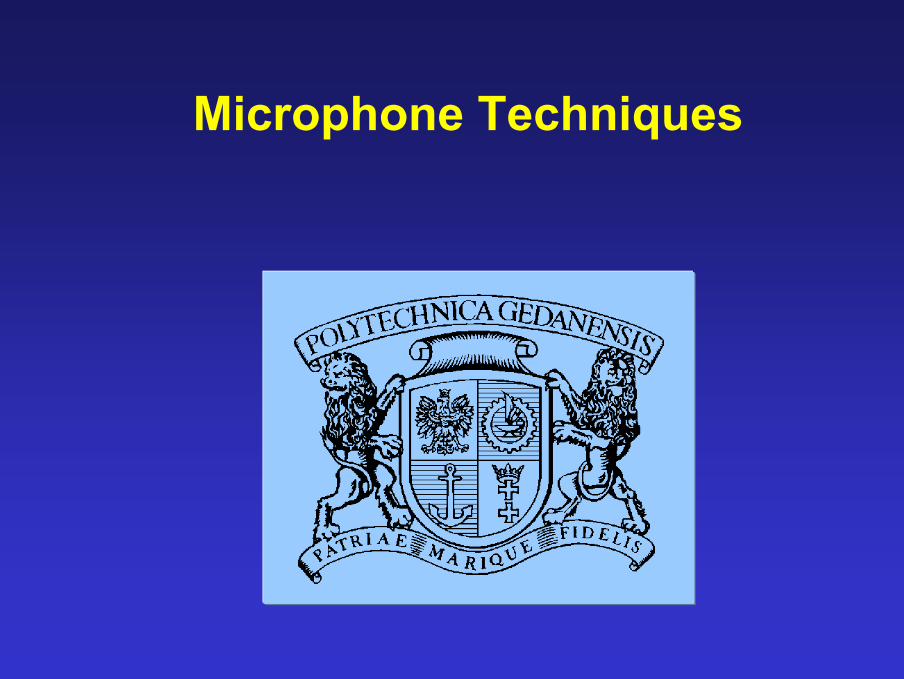
Recording the orchestra
Orchestra
stereo mics
ambient mics
close mics
additional m.
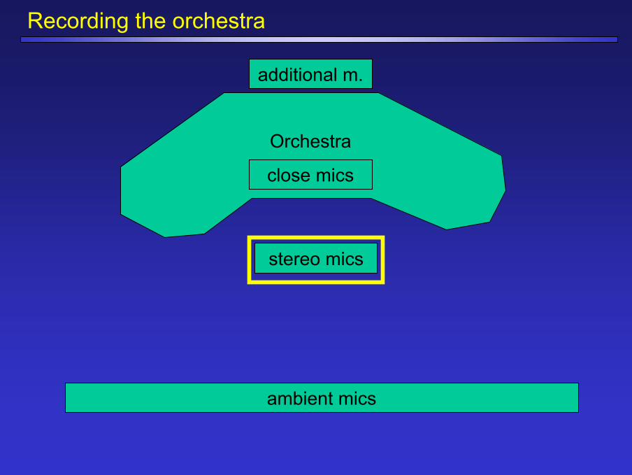
Stereophonic systems
Systemy stereofoniczne
Natężeniowe
(koincydencyjne)
Fazowe
Natężeniowo-Fazowe
(quasi-koincydencyjne)

Stereosonic, Blumlein ArrayOo
α=90o
(+) (+)
(-) (-)
Left Right
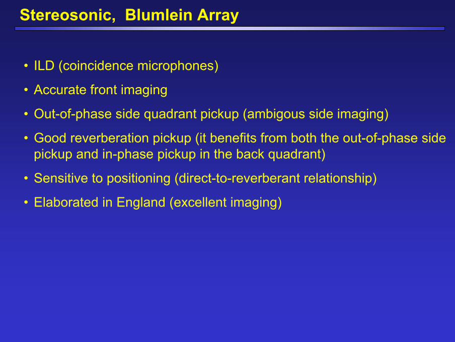
Stereosonic, Blumlein Array
• ILD (coincidence microphones)
• Accurate front imaging
• Out-of-phase side quadrant pickup (ambigous side imaging)
• Good reverberation pickup (it benefits from both the out-of-phase sidepickup and in-phase pickup in the back quadrant)
• Sensitive to positioning (direct-to-reverberant relationship)
• Elaborated in England (excellent imaging)
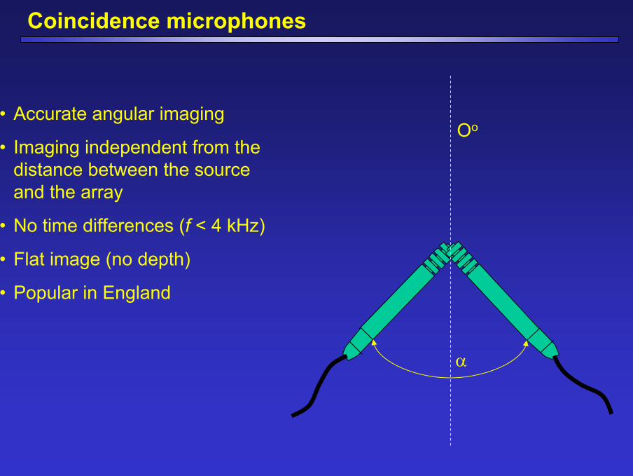
Coincidence microphones
Oo
α
• Accurate angular imaging
• Imaging independent from the distance between the source and the array
• No time differences (f < 4 kHz)
• Flat image (no depth)
• Popular in England
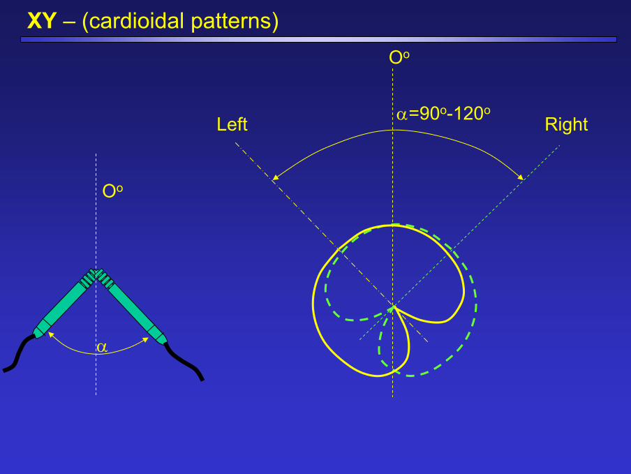
XY – (cardioidal patterns)
Oo
α
Oo
α=90o-120oLeft Right
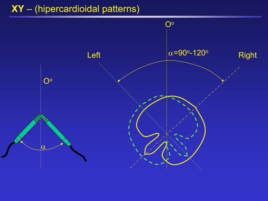
XY – (hipercardioidal patterns)Oo
α=90o-120oLeft Right
Oo
α
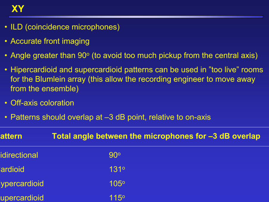
XY
• ILD (coincidence microphones)
• Accurate front imaging
• Angle greater than 90o (to avoid too much pickup from the central axis)
• Hipercardioid and supercardioid patterns can be used in ”too live” roomsfor the Blumlein array (this allow the recording engineer to move awayfrom the ensemble)
• Off-axis coloration
• Patterns should overlap at –3 dB point, relative to on-axis
Pattern Total angle between the microphones for –3 dB overlap
Bidirectional 90o
Cardioid 131o
Hypercardioid 105o
Supercardioid 115o
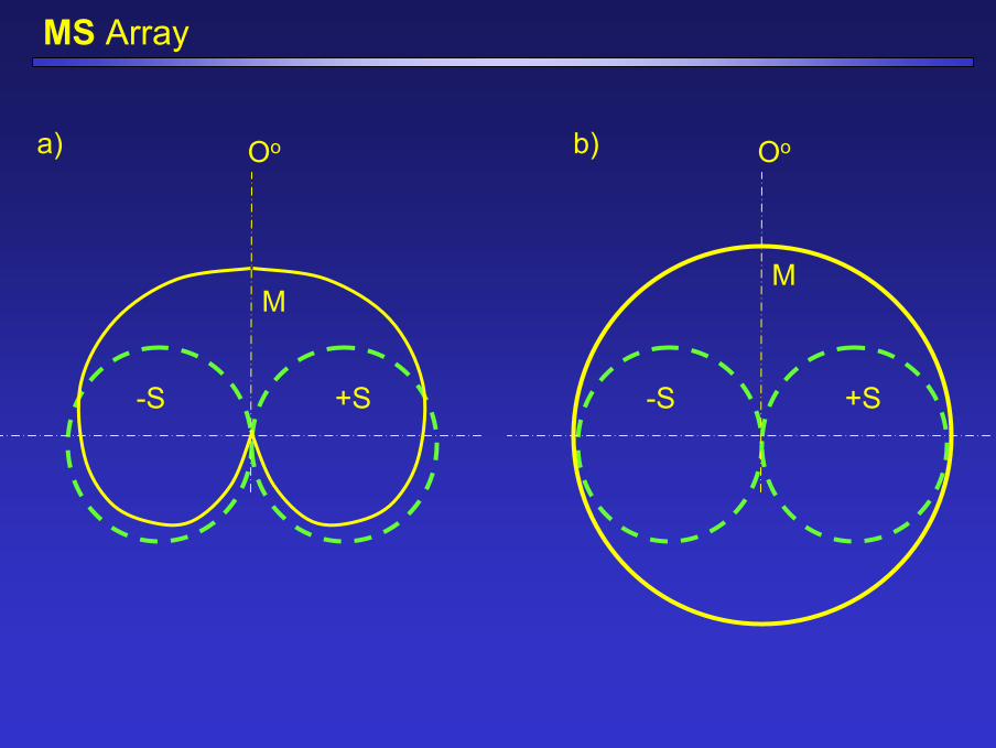
MS Array
Oo
M
-S +S
Oo
M
-S +S
a) b)
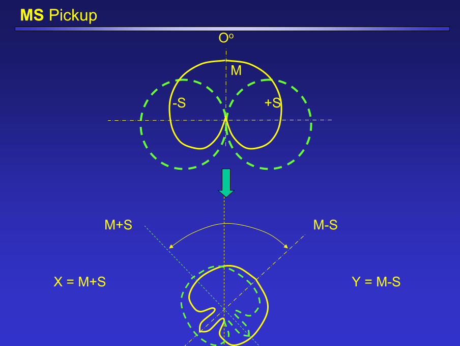
MS PickupOo
M
-S +S
M-SM+S
Y = M-SX = M+S
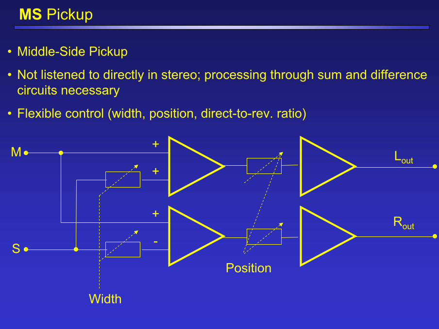
MS Pickup
• Middle-Side Pickup
• Not listened to directly in stereo; processing through sum and differencecircuits necessary
• Flexible control (width, position, direct-to-rev. ratio)
M
S
Lout
Rout
Width
Position
+
+
+
-
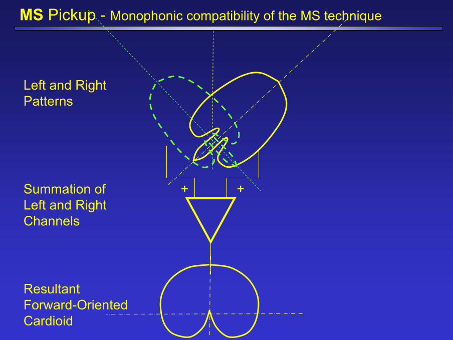
MS Pickup - Monophonic compatibility of the MS technique
+ +
Left and RightPatterns
Summation ofLeft and RightChannels
ResultantForward-OrientedCardioid
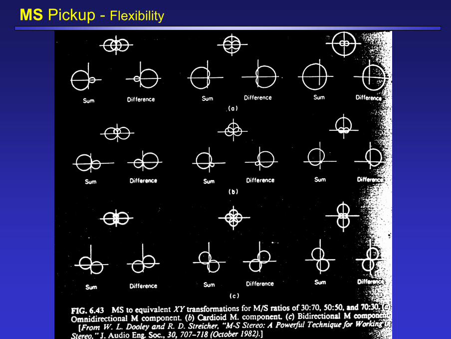
MS Pickup - Flexibility
MS Pickup
• ILD (coincidence microphones)
• Accurate front imaging (depends on M-S ration)
• Remote control
• Flexibility
• Coincident arrays popular in England (excellent front imaging)
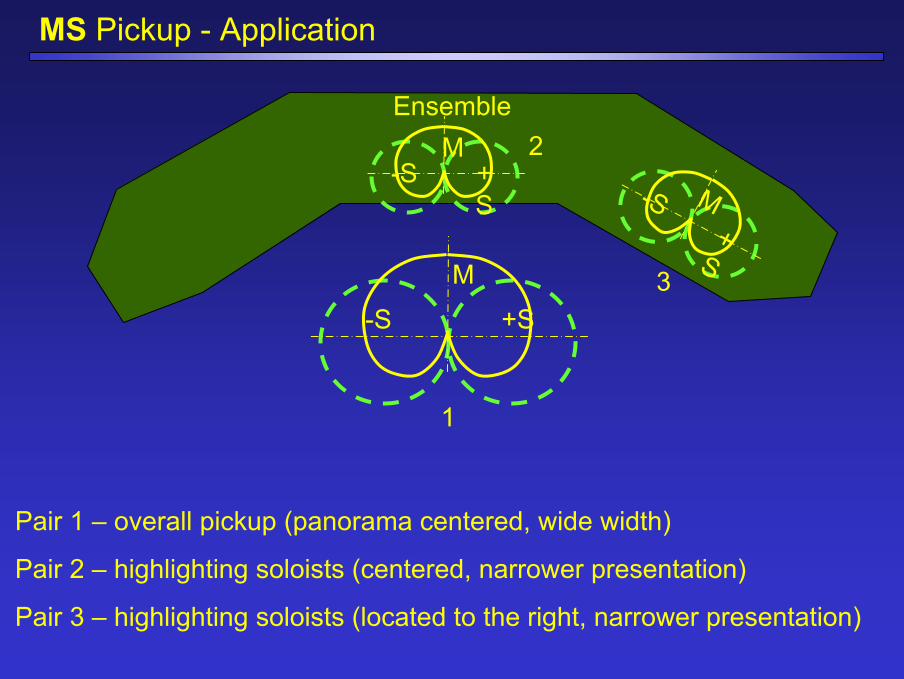
MS Pickup - Application
Ensemble
M
-S +S
M-S +
S M-S+
S
1
2
3
Pair 1 – overall pickup (panorama centered, wide width)
Pair 2 – highlighting soloists (centered, narrower presentation)
Pair 3 – highlighting soloists (located to the right, narrower presentation)
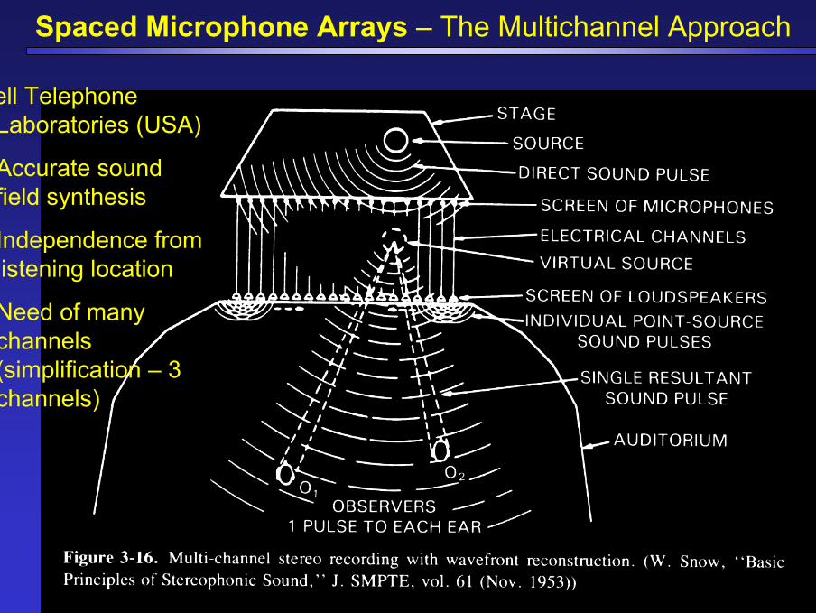
Spaced Microphone Arrays – The Multichannel Approach
Bell Telephone Laboratories (USA)
• Accurate sound field synthesis
• Independence from listening location
• Need of many channels (simplification – 3 channels)
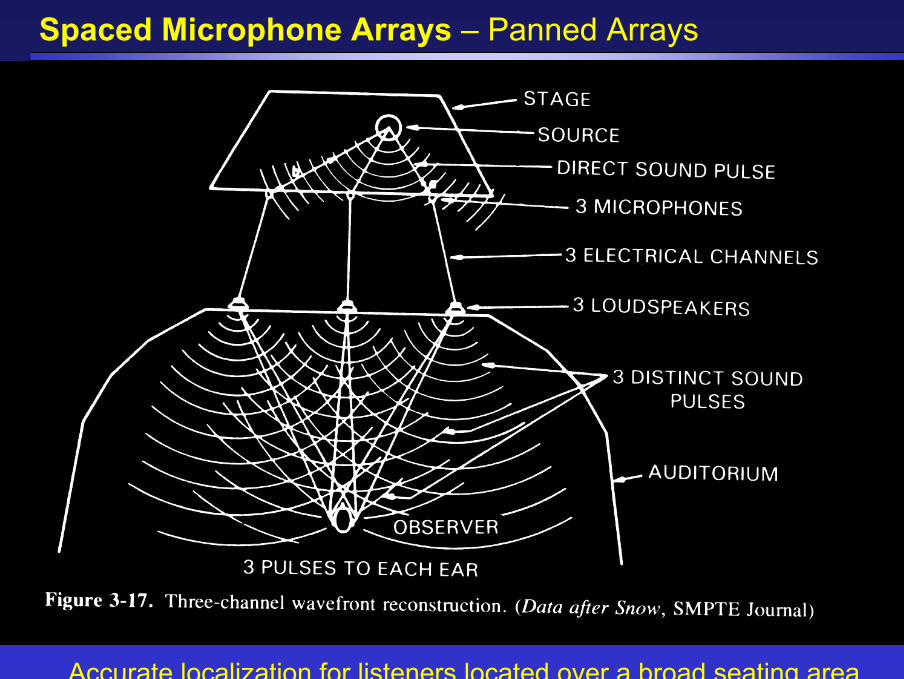
Spaced Microphone Arrays – Panned Arrays
Accurate localization for listeners located over a broad seating area
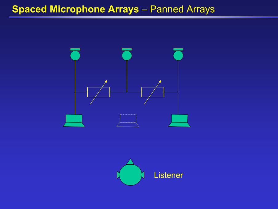
Spaced Microphone Arrays – Panned Arrays
Listener
Spaced Microphone Arrays – Panned Arrays
• Popular in USA
• Center microphone – panned centrally (a phantom center image)
• The total distance (left-center-right) = 3…4 m (depends on the size of the ensemble)
• The level of the center microphone = -6 dB (about)
• ITD
• Good reproduction of early reflections through loudspeakers
• Engineer can control time delays between loudspeakers by microphone placement (advantage)
• Give sense of the environment (ambience)
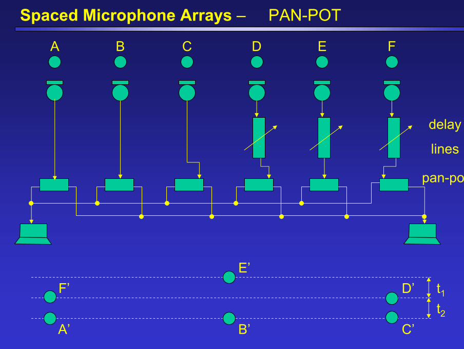
Spaced Microphone Arrays – PAN-POT
A B C D E F
delay
lines
t1t2
A’
F’E’
B’ C’
D’
pan-pot
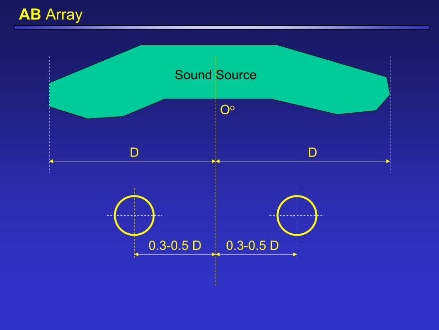
AB Array
Sound Source
Oo
DD
0.3-0.5 D 0.3-0.5 D
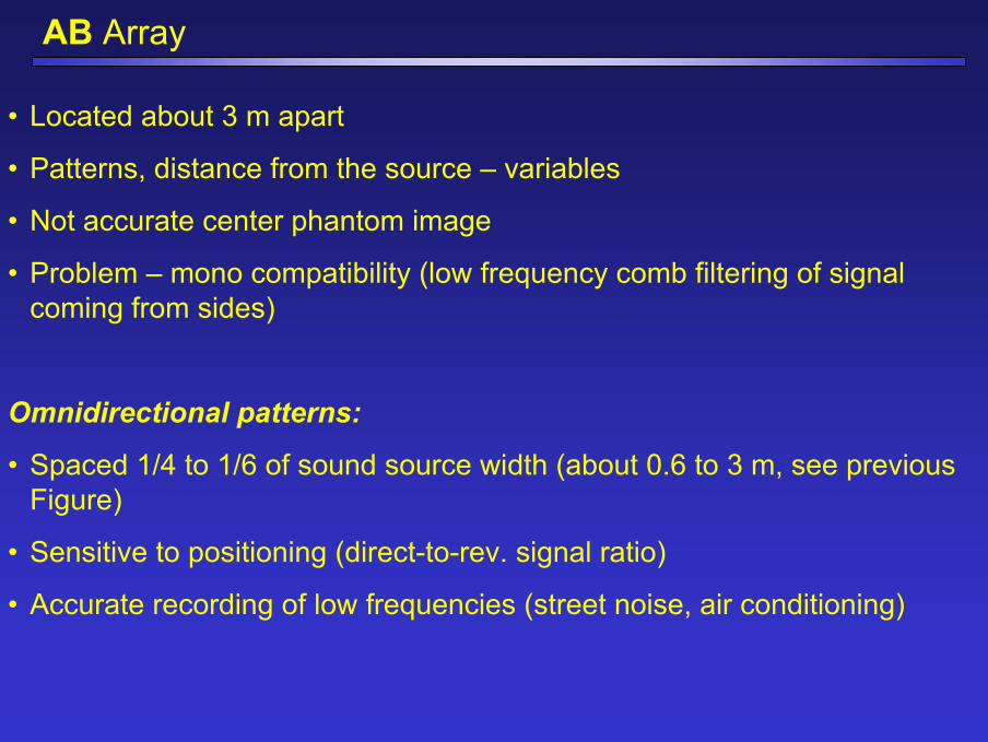
AB Array
• Located about 3 m apart
• Patterns, distance from the source – variables
• Not accurate center phantom image
• Problem – mono compatibility (low frequency comb filtering of signal coming from sides)
Omnidirectional patterns:
• Spaced 1/4 to 1/6 of sound source width (about 0.6 to 3 m, see previous Figure)
• Sensitive to positioning (direct-to-rev. signal ratio)
• Accurate recording of low frequencies (street noise, air conditioning)
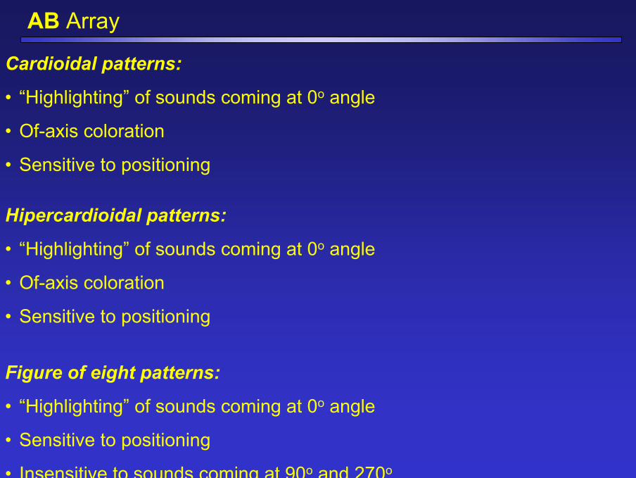
AB Array
Cardioidal patterns:
• “Highlighting” of sounds coming at 0o angle
• Of-axis coloration
• Sensitive to positioning
Figure of eight patterns:
• “Highlighting” of sounds coming at 0o angle
• Sensitive to positioning
• Insensitive to sounds coming at 90o and 270o
Hipercardioidal patterns:
• “Highlighting” of sounds coming at 0o angle
• Of-axis coloration
• Sensitive to positioning
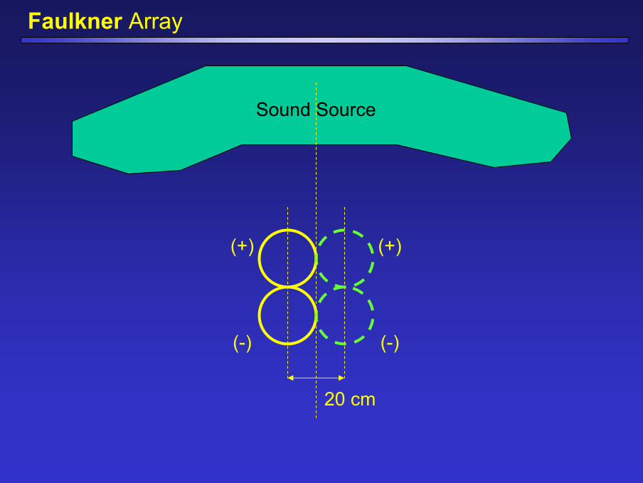
Faulkner Array
Sound Source
20 cm
(+)(+)
(-)(-)
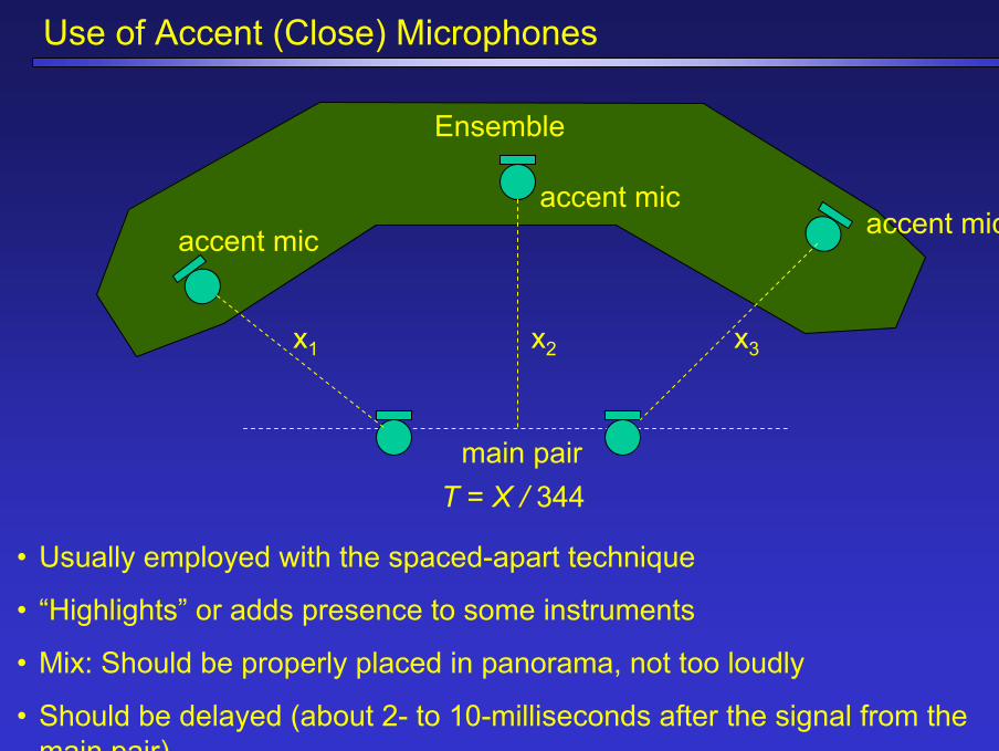
Use of Accent (Close) Microphones
Ensemble
x1 x2 x3
T = X / 344
• Usually employed with the spaced-apart technique
• “Highlights” or adds presence to some instruments
• Mix: Should be properly placed in panorama, not too loudly
• Should be delayed (about 2- to 10-milliseconds after the signal from the main pair)
main pair
accent micaccent mic
accent mic
Quasi-Coincident Microphone Arrays
• Pair of directional microphones spaced no more than about 30 cm
• The intent: Combine excellent imaging of the coincident arrays and the added sense of space or ambience
Examples:
• ORTF
• NOS
• Stereo-180 Array
• Bidirectional Microphones with Baffle
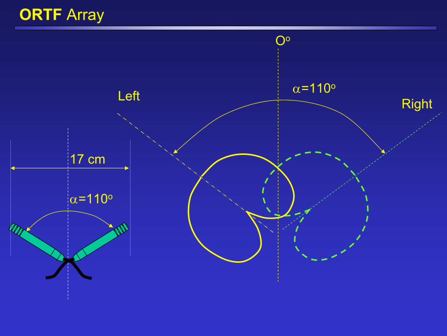
ORTF ArrayOo
α=110o
17 cm
α=110o
Left Right
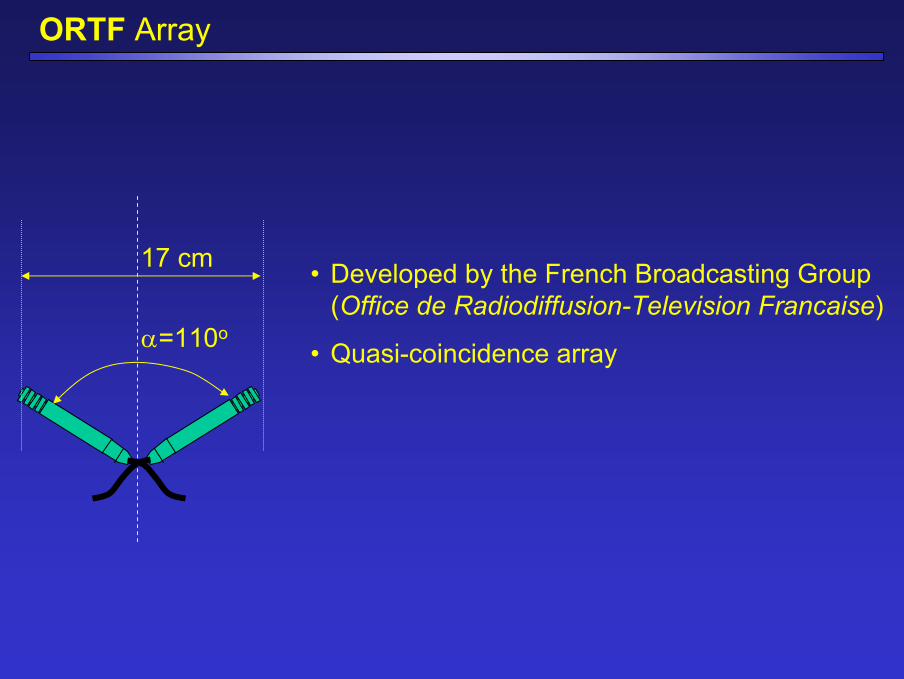
ORTF Array
17 cm
α=110o
• Developed by the French Broadcasting Group (Office de Radiodiffusion-Television Francaise)
• Quasi-coincidence array
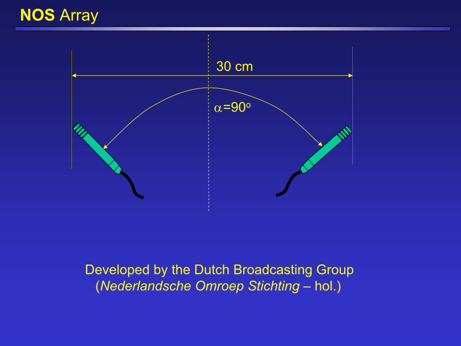
NOS Array
30 cm
α=90o
Developed by the Dutch Broadcasting Group (Nederlandsche Omroep Stichting – hol.)
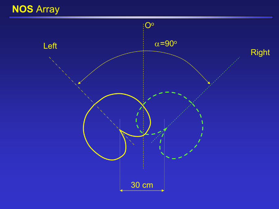
NOS ArrayOo
α=90oLeftRight
30 cm
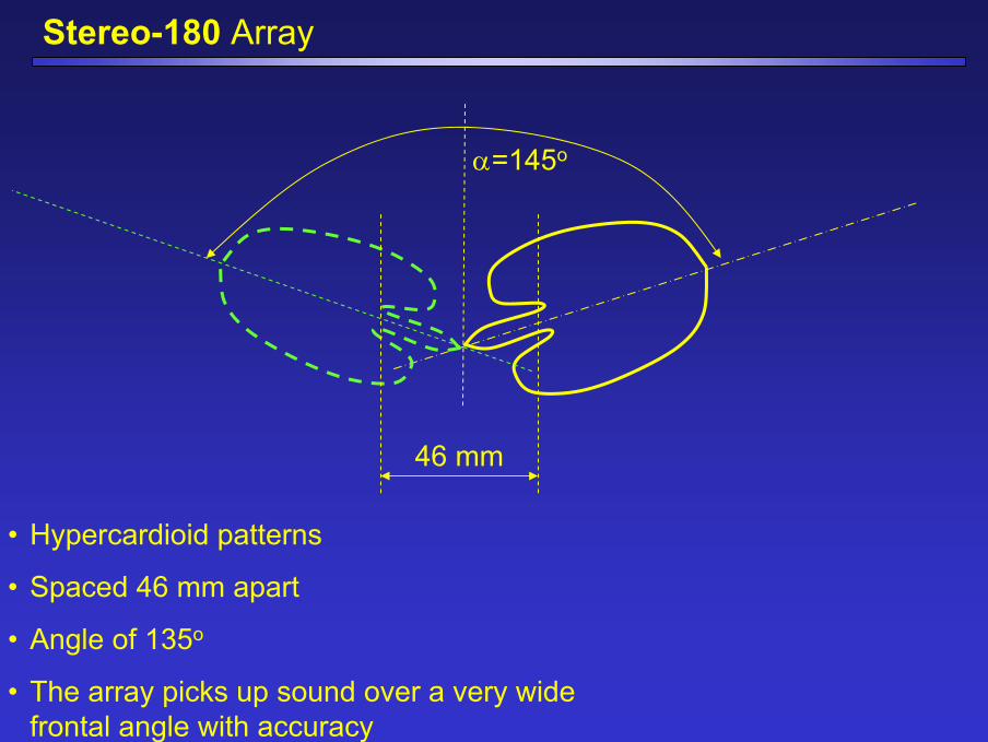
Stereo-180 Array
α=145o
46 mm
• Hypercardioid patterns
• Spaced 46 mm apart
• Angle of 135o
• The array picks up sound over a very wide frontal angle with accuracy
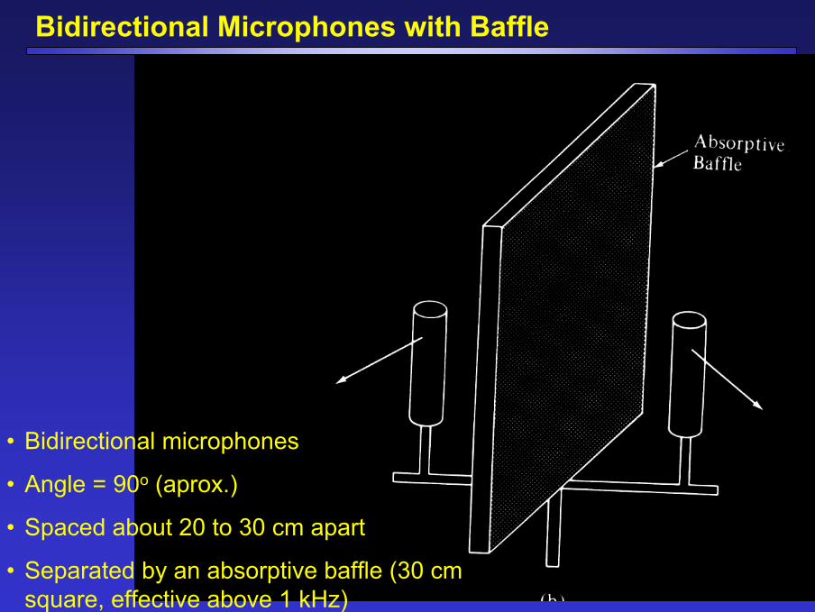
Bidirectional Microphones with Baffle
• Bidirectional microphones
• Angle = 90o (aprox.)
• Spaced about 20 to 30 cm apart
• Separated by an absorptive baffle (30 cm square, effective above 1 kHz)
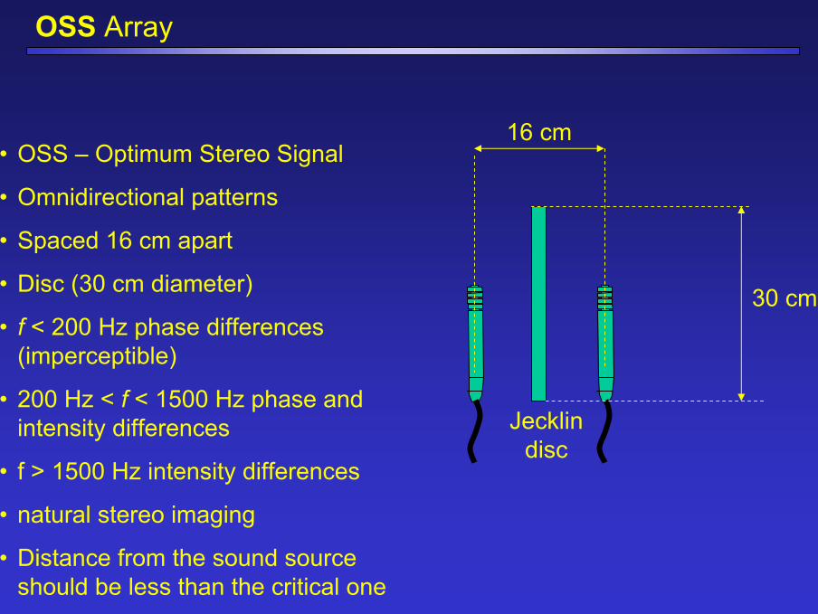
OSS Array
16 cm
Jecklindisc
30 cm
• OSS – Optimum Stereo Signal
• Omnidirectional patterns
• Spaced 16 cm apart
• Disc (30 cm diameter)
• f < 200 Hz phase differences (imperceptible)
• 200 Hz < f < 1500 Hz phase and intensity differences
• f > 1500 Hz intensity differences
• natural stereo imaging
• Distance from the sound source should be less than the critical one
PZM
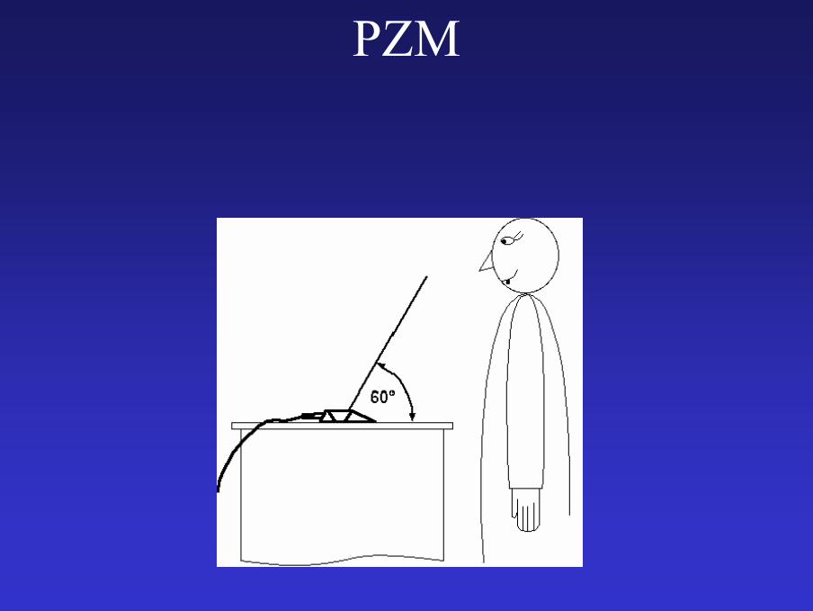
Mikrofon PZM na biurku lektoraSkierowanie mikrofonu osią główną w kierunku powierzchni przegrody zmniejsza typowe dla mikrofonów dookólnych podbicie wysokich tonów (jakie występuje właśnie na osi głównej mikrofonu) Umieszczenie mikrofonów na naturalnej powierzchni granicznej, jaką jest ściana może być o tyle problematyczne, że odległość mikrofonów od muzyków w typowym studio będzie zbyt duża, co może niekorzystnie wpłynąć na różne cechy nagrania. Rozwiązaniem tego problemu jest umieszczenie mikrofonów na sztucznej powierzchni (specjalna płyta z umieszczonym na niej mikrofonem), którą można ustawiać w dowolnej odległości od nagrywanego zespołu.
PZM
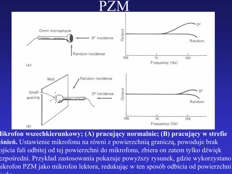
Mikrofon wszechkierunkowy; (A) pracujący normalnie; (B) pracujący w strefie ciśnień. Ustawienie mikrofonu na równi z powierzchnią graniczą, powoduje brak dojścia fali odbitej od tej powierzchni do mikrofonu, zbiera on zatem tylko dźwięk bezpośredni. Przykład zastosowania pokazuje powyższy rysunek, gdzie wykorzystano mikrofon PZM jako mikrofon lektora, redukując w ten sposób odbicia od powierzchni biurka.
PZM
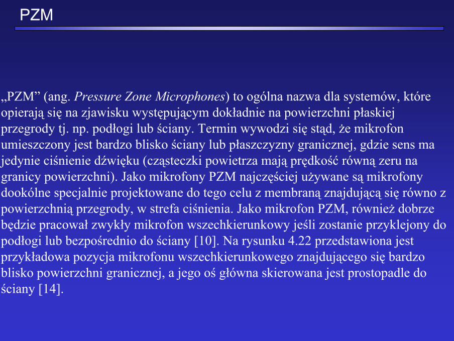
„PZM” (ang. Pressure Zone Microphones) to ogólna nazwa dla systemów, które opierają się na zjawisku występującym dokładnie na powierzchni płaskiej przegrody tj. np. podłogi lub ściany. Termin wywodzi się stąd, że mikrofon umieszczony jest bardzo blisko ściany lub płaszczyzny granicznej, gdzie sens ma jedynie ciśnienie dźwięku (cząsteczki powietrza mają prędkość równą zeru na granicy powierzchni). Jako mikrofony PZM najczęściej używane są mikrofony dookólne specjalnie projektowane do tego celu z membraną znajdującą się równo z powierzchnią przegrody, w strefa ciśnienia. Jako mikrofon PZM, również dobrze będzie pracował zwykły mikrofon wszechkierunkowy jeśli zostanie przyklejony do podłogi lub bezpośrednio do ściany [10]. Na rysunku 4.22 przedstawiona jest przykładowa pozycja mikrofonu wszechkierunkowego znajdującego się bardzo blisko powierzchni granicznej, a jego oś główna skierowana jest prostopadle do ściany [14].
PZM
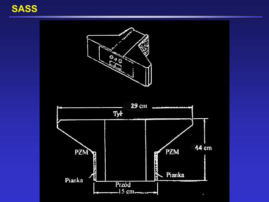
SASS
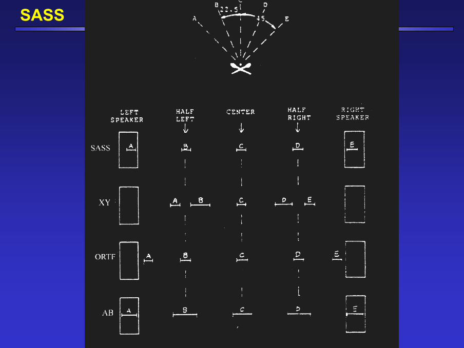
SASS
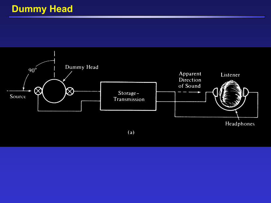
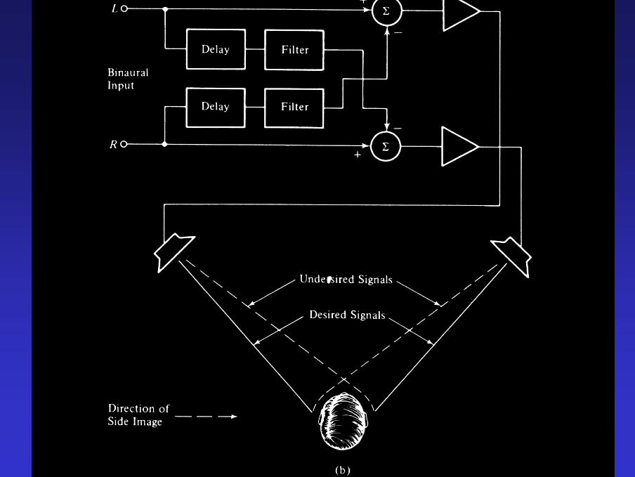
Dummy Head

Sztuczna głowa
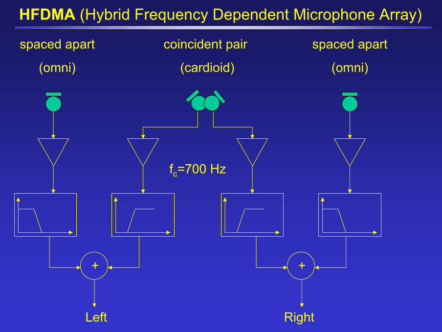
HFDMA (Hybrid Frequency Dependent Microphone Array)
coincident pair
(cardioid)
spaced apart
(omni)
spaced apart
(omni)
+ +
Left Right
fc=700 Hz
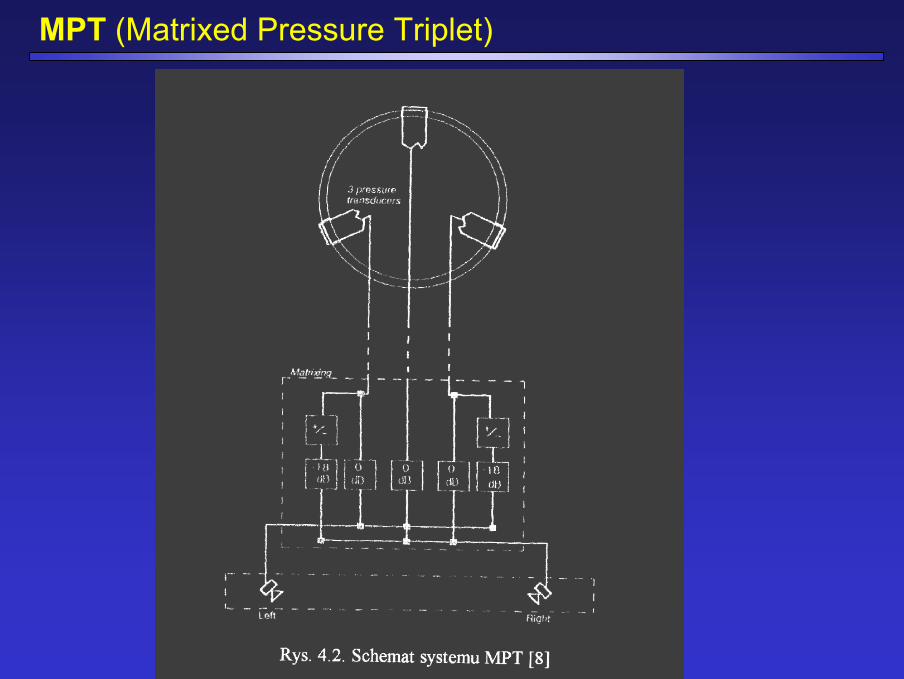
MPT (Matrixed Pressure Triplet)
MPT (Matrixed Pressure Triplet)
MPT (Matrixed Pressure Triplet)
Soundfield