Embed Size (px)
Citation preview
MICROWAVE DEVICES & SYSTEMS
BY
Mr.V.Sudheer Raja, M.TechAssistant professor , Department of Electrical Engineering
Adama Science and Technology UniversityE-Mail : [email protected]
Mr.V. Sudheer Raja
Chapter 1Chapter 1Microwave Transmission Microwave Transmission
lineslines Microwave Spectrum and bands Microwave Properties Advantages & Limitations Applications Rectangular Waveguides Circular waveguides
Mr.V. Sudheer Raja
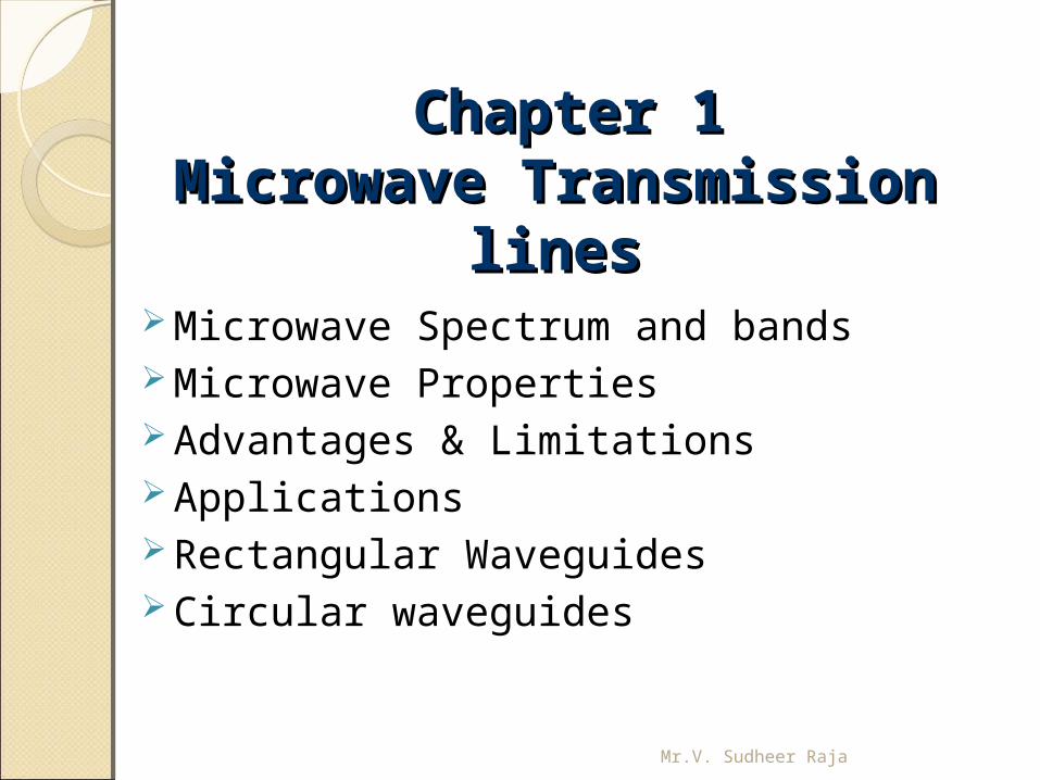
Electro Magnetic Spectrum
Mr.V. Sudheer Raja
MicrowavesMicrowavesMicrowaves are electromagnetic waves whose frequencies range from about 1GHz – 300 GHz and wavelengths in air ranging from nearly 30 cm – 1 mm. The word Microwave means very short wave, which is the shortest wavelength region of the radio spectrum and a part of the electromagnetic spectrum.Microwave really indicates the wavelength in micron ranges.
Mr.V. Sudheer Raja
Properties of MicrowavesProperties of Microwaves1. Microwave is an electromagnetic radiation of
short wavelength.2. They can reflect by conducting surfaces just
like optical waves since they travel in straight line.
3. Microwave currents flow through a thin outer layer of an ordinary cable.
4. Microwaves are easily attenuated within short distances.
5. They are not reflected by ionosphere
Mr.V. Sudheer Raja
Advantages and LimitationsAdvantages and Limitations 1. Increased bandwidth availability: Microwaves have large bandwidths compared to the
common bands like short waves (SW), ultrahigh frequency (UHF) waves, etc.
For example, the microwaves extending from = 1 cm - = 10 cm (i.e) from 30,000 MHz – 3000 MHz, this region has a bandwidth of 27,000 MHz.
2. Improved directive properties: The second advantage of microwaves is their ability
to use high gain directive antennas, any EM wave can be focused in a specified direction (Just as the focusing of light rays with lenses or reflectors)
Mr.V. Sudheer Raja
Advantages and LimitationsAdvantages and Limitations 3. Fading effect and reliability: Fading effect due to the variation in the transmission
medium is more effective at low frequency. Due to the Line of Sight (LOS) propagation and high
frequencies, there is less fading effect and hence microwave communication is more reliable.
4. Power requirements: Transmitter / receiver power requirements are pretty
low at microwave frequencies compared to that at short wave band.
Mr.V. Sudheer Raja
Advantages and LimitationsAdvantages and Limitations
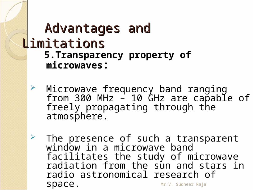
5.Transparency property of microwaves:
Microwave frequency band ranging from 300 MHz – 10 GHz are capable of freely propagating through the atmosphere.
The presence of such a transparent window in
a microwave band facilitates the study of microwave radiation from the sun and stars in radio astronomical research of space.
Mr.V. Sudheer Raja
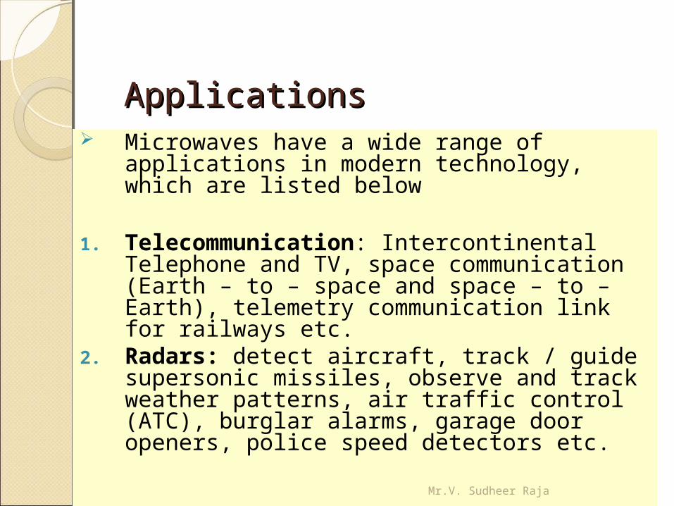
ApplicationsApplications Microwaves have a wide range of applications in
modern technology, which are listed below
1. Telecommunication: Intercontinental Telephone and TV, space communication (Earth – to – space and space – to – Earth), telemetry communication link for railways etc.
2. Radars: detect aircraft, track / guide supersonic missiles, observe and track weather patterns, air traffic control (ATC), burglar alarms, garage door openers, police speed detectors etc.
Mr.V. Sudheer Raja

3.Commercial and industrial applications
Microwave oven Drying machines – textile, food and paper industry
for drying clothes, potato chips, printed matters etc.
Food process industry – Precooling / cooking, pasteurization / sterility, hat frozen / refrigerated precooled meats, roasting of food grains / beans.
Rubber industry / plastics / chemical / forest product industries
Mining / public works, breaking rocks, tunnel boring, drying / breaking up concrete, breaking up coal seams, curing of cement.
Drying inks / drying textiles, drying / sterilizing grains, drying / sterilizing pharmaceuticals, leather, tobacco, power transmission.
Biomedical Applications ( diagnostic / therapeutic ) – diathermy for localized superficial heating, deep electromagnetic heating for treatment of cancer, hyperthermia ( local, regional or whole body for cancer therapy). Mr.V. Sudheer Raja
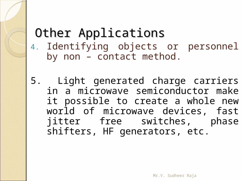
Other ApplicationsOther Applications4. Identifying objects or personnel by non –
contact method.
5. Light generated charge carriers in a microwave semiconductor make it possible to create a whole new world of microwave devices, fast jitter free switches, phase shifters, HF generators, etc.
Mr.V. Sudheer Raja
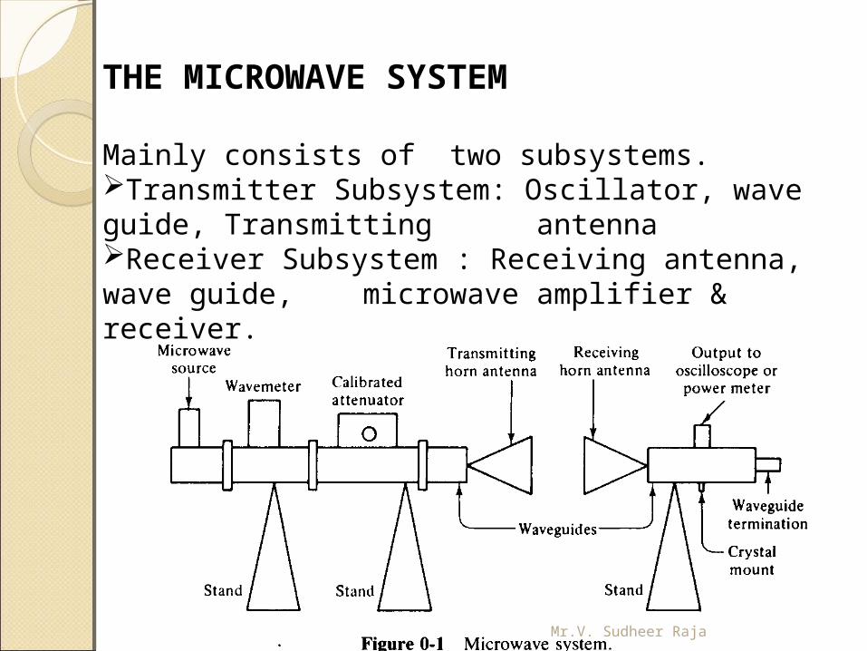
THE MICROWAVE SYSTEM
Mainly consists of two subsystems.Transmitter Subsystem: Oscillator, wave guide, Transmitting antennaReceiver Subsystem : Receiving antenna, wave guide, microwave amplifier & receiver.
Mr.V. Sudheer Raja
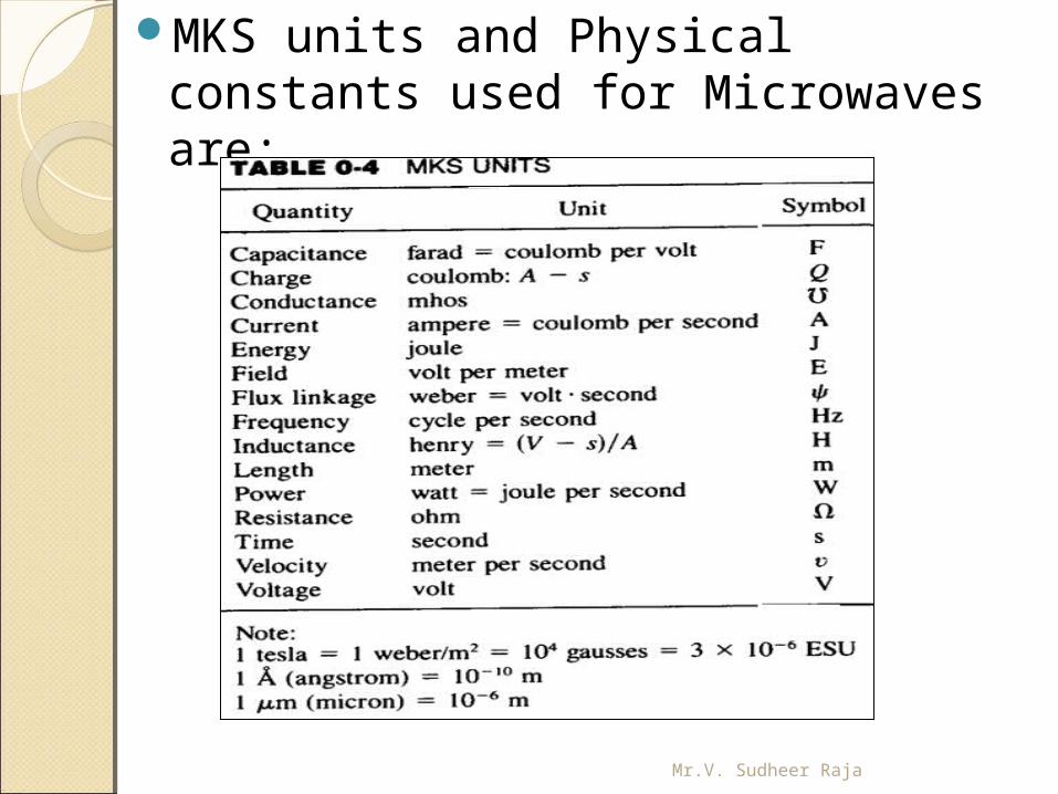
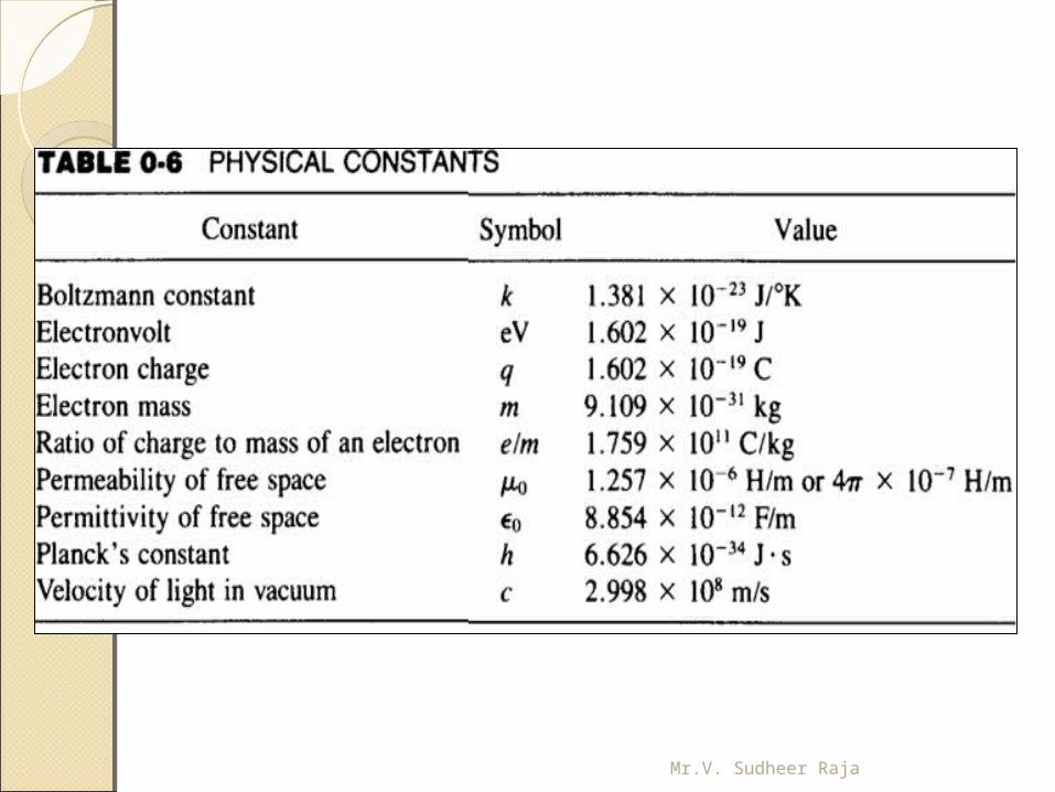
MKS units and Physical constants used for Microwaves are:
Mr.V. Sudheer Raja
Mr.V. Sudheer Raja
WaveguidesWaveguides
Wave guideBasic featuresRectangular Wave guideCircular Wave guideApplications
Mr.V. Sudheer Raja
WaveguidesWaveguides
Introduction
At frequencies higher than 3 GHz, transmission of electromagnetic energy along the transmission lines and cables becomes difficult.
This is due to the losses that occur both in the solid dielectric needed to support the conductor and in the conductors themselves.
A metallic tube can be used to transmit electromagnetic wave at the above frequencies
Mr.V. Sudheer Raja
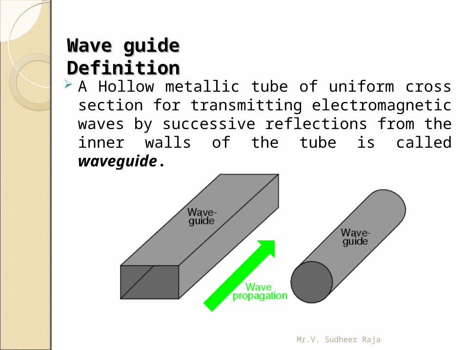
Wave guide Wave guide DefinitionDefinition A Hollow metallic tube of uniform cross section for
transmitting electromagnetic waves by successive reflections from the inner walls of the tube is called waveguide.
Mr.V. Sudheer Raja
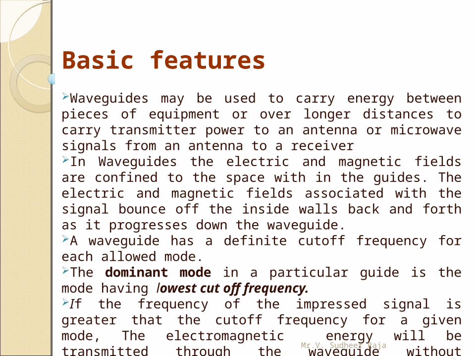
Basic featuresWaveguides may be used to carry energy between pieces of equipment or over longer distances to carry transmitter power to an antenna or microwave signals from an antenna to a receiverIn Waveguides the electric and magnetic fields are confined to the space with in the guides. The electric and magnetic fields associated with the signal bounce off the inside walls back and forth as it progresses down the waveguide. A waveguide has a definite cutoff frequency for each allowed mode.The dominant mode in a particular guide is the mode having lowest cut off frequency. If the frequency of the impressed signal is greater that the cutoff frequency for a given mode, The electromagnetic energy will be transmitted through the waveguide without attenuation, else if the frequency is less than cutoff frequency, signal is attenuated with in the short distance.Waveguides are made from copper, aluminum or brass. These metals are extruded into long rectangular or circular pipes.
Mr.V. Sudheer Raja

Mr.V. Sudheer Raja
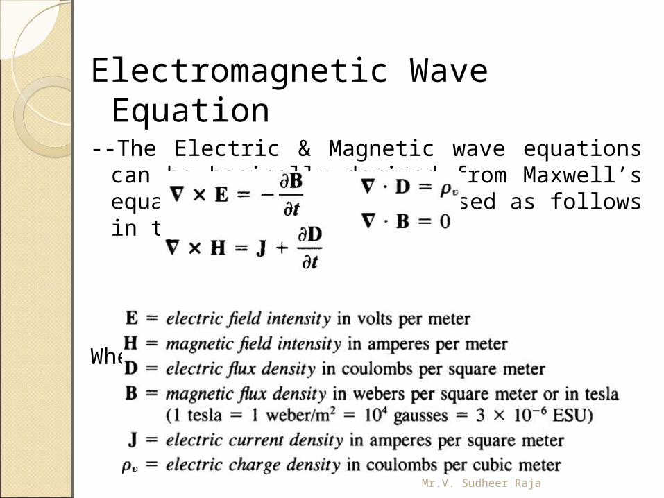
Electromagnetic Wave Equation--The Electric & Magnetic wave equations can be
basically derived from Maxwell’s equations. They are expressed as follows in time domain
Where,
Mr.V. Sudheer Raja
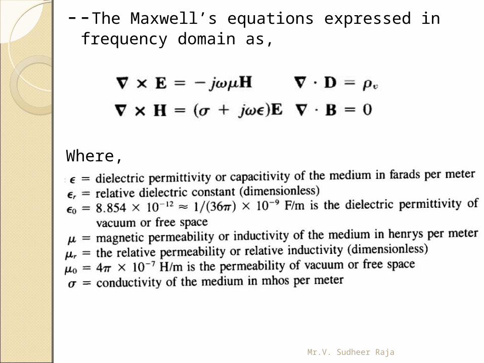
--The Maxwell’s equations expressed in frequency domain as,
Where,
Mr.V. Sudheer Raja
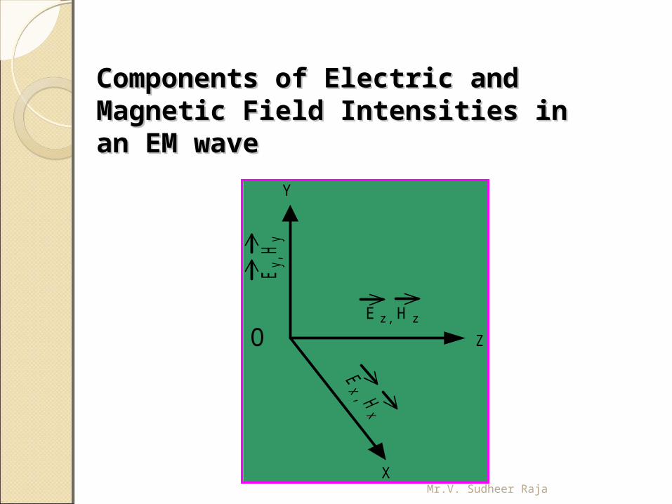
Components of Electric and Components of Electric and Magnetic Field Intensities in an Magnetic Field Intensities in an EM waveEM wave
O
X
Y
Z
E z, H z
Ey,
Hy
Mr.V. Sudheer Raja
EM field configuration within the EM field configuration within the waveguide waveguide In order to determine the EM field configuration within the waveguide, Maxwell’s equations should be solved subject to appropriate boundary conditions at the walls of the guide.
Such solutions give rise to a number of field configurations. Each configuration is known as a mode. The following are the different modes possible in a waveguide system
Mr.V. Sudheer Raja
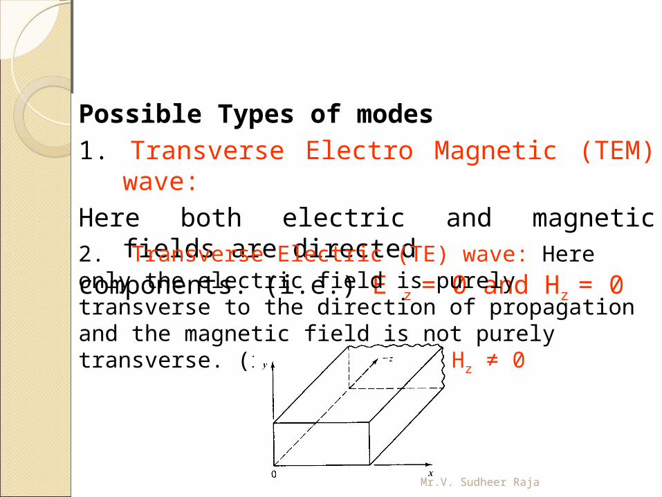
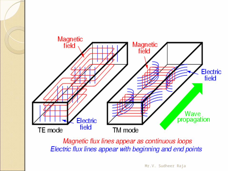
Possible Types of modes1. Transverse Electro Magnetic (TEM) wave:
Here both electric and magnetic fields are directed
components. (i.e.) E z = 0 and Hz = 0
2. Transverse Electric (TE) wave: Here only the electric field is purely transverse to the direction of propagation and the magnetic field is not purely transverse. (i.e.) E z
= 0, Hz ≠ 0
Mr.V. Sudheer Raja
4. Hybrid (HE) wave: Here neither electric nor magnetic fields are purely transverse to the direction of propagation. (i.e.) E z ≠ 0, Hz ≠ 0.
3. Transverse Magnetic (TM) wave: Here only magnetic field is transverse to the direction of propagation and the electric field is not purely transverse. (i.e.) E z ≠ 0, Hz = 0.
Possible Types of modes
Mr.V. Sudheer Raja
Mr.V. Sudheer Raja
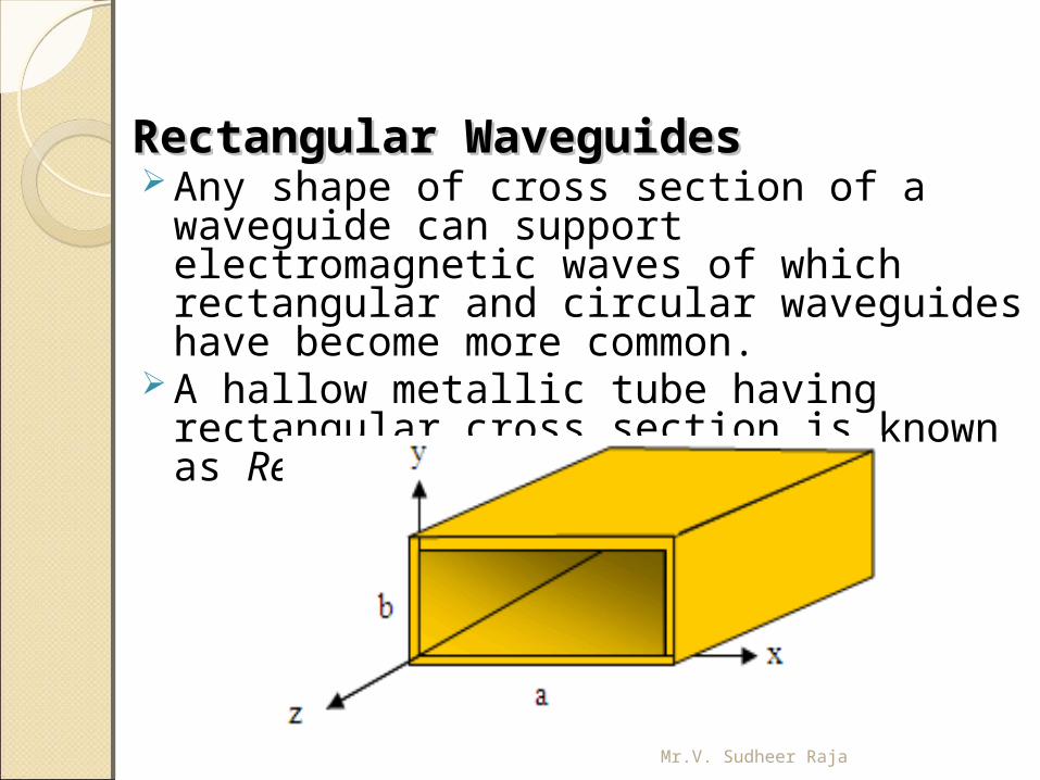
Rectangular WaveguidesRectangular Waveguides Any shape of cross section of a waveguide can
support electromagnetic waves of which rectangular and circular waveguides have become more common.
A hallow metallic tube having rectangular cross section is known as Rectangular waveguide
Mr.V. Sudheer Raja
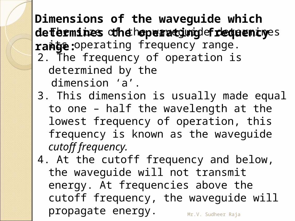
1. The size of the waveguide determines its operating frequency range.
2. The frequency of operation is determined by the dimension ‘a’. 3. This dimension is usually made equal to one –
half the wavelength at the lowest frequency of operation, this frequency is known as the waveguide cutoff frequency.
4. At the cutoff frequency and below, the waveguide will not transmit energy. At frequencies above the cutoff frequency, the waveguide will propagate energy.
Dimensions of the waveguide which determines the operating frequency range:
Mr.V. Sudheer Raja
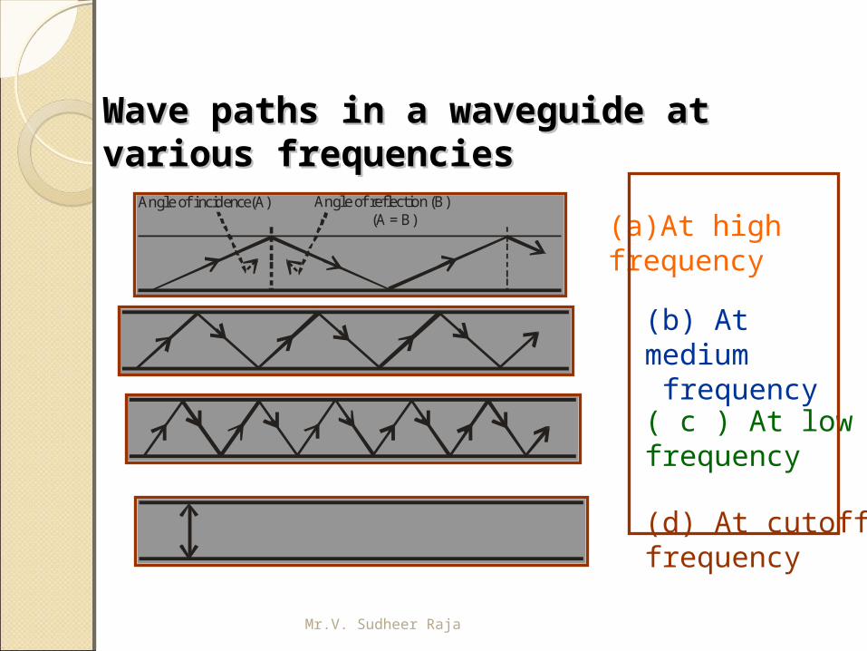
Wave paths in a waveguide at Wave paths in a waveguide at various frequenciesvarious frequencies
Angle of incidence(A) Angle of reflection (B)(A = B) (a)At high
frequency
(b) At medium frequency
( c ) At low frequency
(d) At cutoff frequency
Mr.V. Sudheer Raja
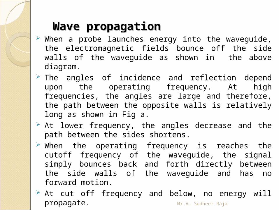
Wave propagationWave propagation When a probe launches energy into the waveguide, the
electromagnetic fields bounce off the side walls of the waveguide as shown in the above diagram.
The angles of incidence and reflection depend upon the operating frequency. At high frequencies, the angles are large and therefore, the path between the opposite walls is relatively long as shown in Fig a.
At lower frequency, the angles decrease and the path between the sides shortens.
When the operating frequency is reaches the cutoff frequency of the waveguide, the signal simply bounces back and forth directly between the side walls of the waveguide and has no forward motion.
At cut off frequency and below, no energy will propagate.Mr.V. Sudheer Raja
Cut off frequencyCut off frequency The exact size of the wave guide is selected
based on the desired operating frequency. The size of the waveguide is chosen so that
its rectangular width is greater than one – half the wavelength but less than the one wavelength at the operating frequency.
This gives a cutoff frequency that is below the operating frequency, thereby ensuring that the signal will be propagated down the line.
Mr.V. Sudheer Raja
Representation of modesRepresentation of modes The general symbol of representation will be
TE m, n or TM m, n where the subscript m indicates the number of half wave variations of the electric field or magnetic intensity along the a ( wide) dimension of the waveguide i.e. x- direction.
The second subscript n indicates the number of half wave variations of the electric field or magnetic field in the b (narrow) dimension of the guide i.e. y- direction. If the propagation is in the direction of positive z direction.
The TE 1, 0 mode has the longest operating wavelength and is designated as the dominant mode. It is the mode for the lowest frequency that can be propagated in a waveguide.Mr.V. Sudheer Raja
Expression for cut off wavelengthExpression for cut off wavelength
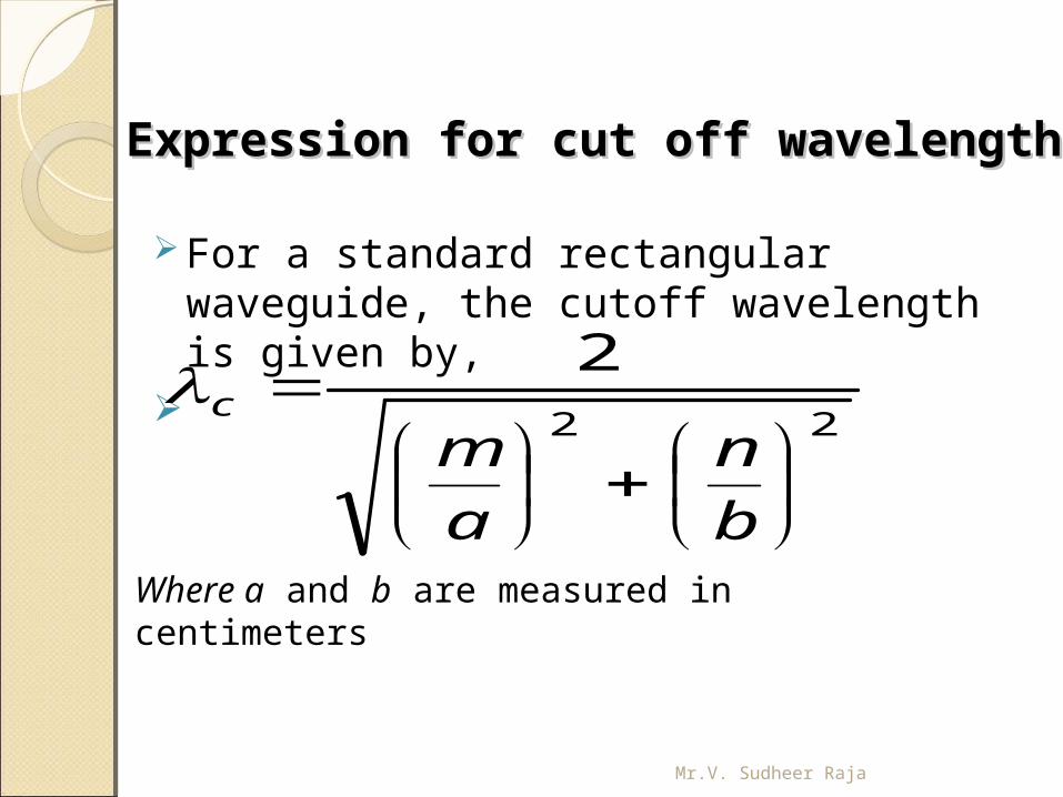
For a standard rectangular waveguide, the cutoff wavelength is given by,
22
2
b
n
a
mc
Where a and b are measured in centimeters
Mr.V. Sudheer Raja
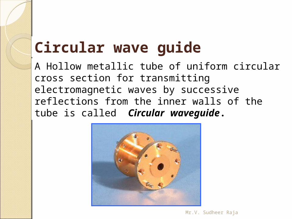
A Hollow metallic tube of uniform circular cross section for transmitting electromagnetic waves by successive reflections from the inner walls of the tube is called Circular waveguide.
Circular wave guide
Mr.V. Sudheer Raja
Circular wave guideCircular wave guide
The circular waveguide is used in many special applications in microwave techniques.
It has the advantage of greater power – handling capacity and lower attenuation for a given cutoff wavelength. However, the disadvantage of somewhat greater size and weight.
The polarization of the transmitted wave can be altered due to the minor irregularities of the wall surface of the circular guide, whereas the rectangular wave guide the polarization is fixed
Mr.V. Sudheer Raja
Mr.V. Sudheer Raja
DescriptionDescription
The wave of lowest frequency or the dominant mode in the circular waveguide is the TE11 mode.
The first subscript m indicates the number of full – wave variations of the radial component of the electric field around the circumference of the waveguide.
The second subscript n indicates the number of half – wave variations across the diameter.
The field configurations of TE11 mode in the circular waveguide is shown in the diagram below Mr.V. Sudheer Raja
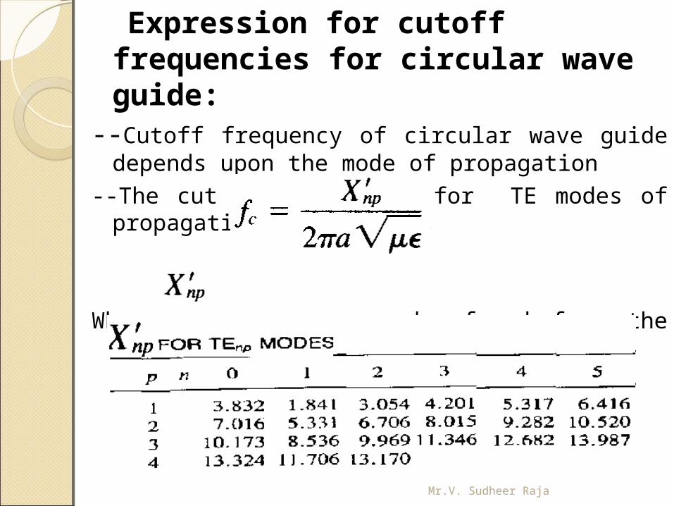
Expression for cutoff frequencies for circular wave guide:
--Cutoff frequency of circular wave guide depends upon the mode of propagation
--The cut off frequency for TE modes of propagation is given as,
Where can be found from the following table,
Mr.V. Sudheer Raja
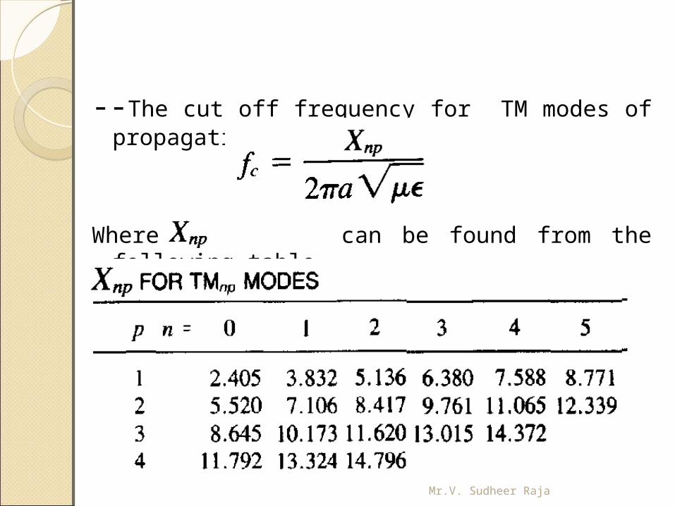
--The cut off frequency for TM modes of propagation is given as,
Where can be found from the following table,
Mr.V. Sudheer Raja
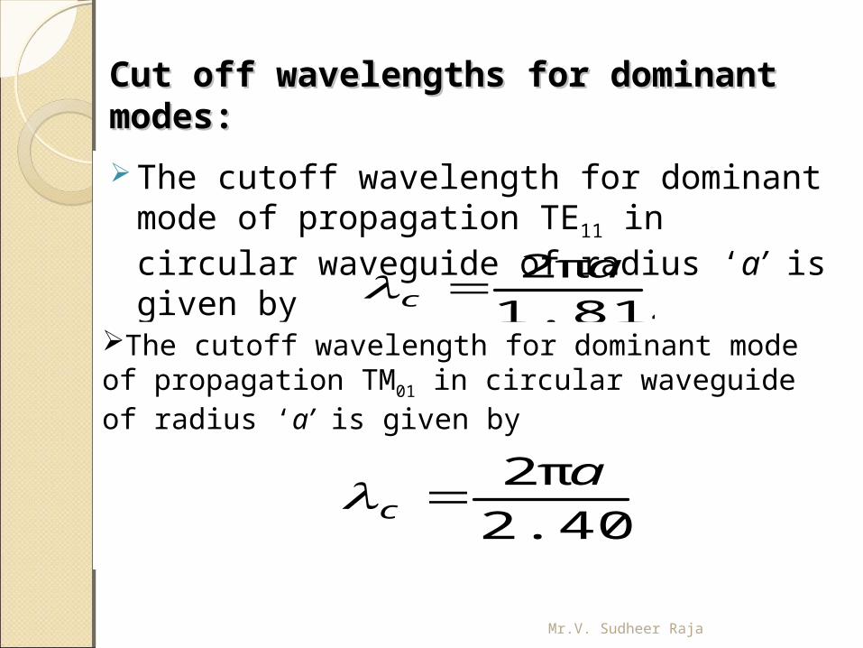
Cut off wavelengths for dominant Cut off wavelengths for dominant modes:modes:
The cutoff wavelength for dominant mode of propagation TE11 in circular waveguide of radius ‘a’ is given by
1.814
π2 ac
The cutoff wavelength for dominant mode of propagation TM01 in circular waveguide of radius ‘a’ is given by
2.405
π2 ac
Mr.V. Sudheer Raja
Applications of Circular waveguideApplications of Circular waveguide Rotating joints in radars to connect the horn
antenna feeding a parabolic reflector (which must rotate for tracking)
TE01 mode suitable for long distance waveguide transmission above 10 GHz.
Short and medium distance broad band communication (could replace / share coaxial and microwave links)
Mr.V. Sudheer Raja
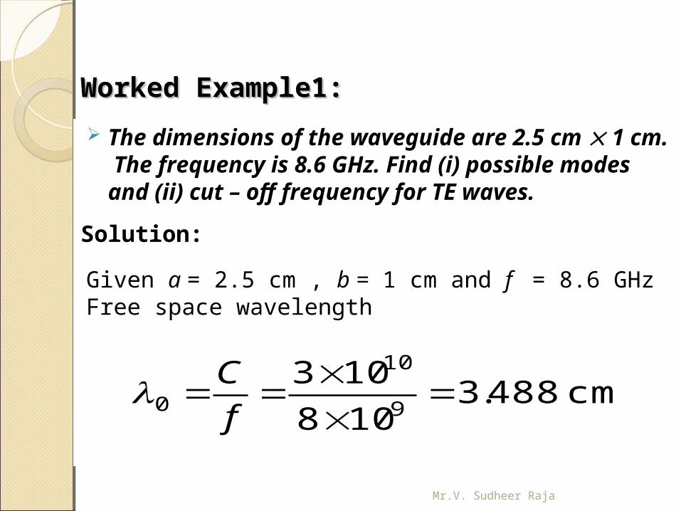
Worked Example1:Worked Example1: The dimensions of the waveguide are 2.5 cm 1
cm. The frequency is 8.6 GHz. Find (i) possible modes and (ii) cut – off frequency for TE waves.
Solution:
Given a = 2.5 cm , b = 1 cm and f = 8.6 GHzFree space wavelength
cm488.3108
1039
10
0
f
C
Mr.V. Sudheer Raja
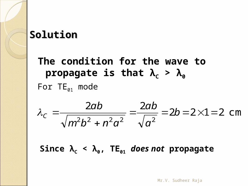
SolutionSolution
The condition for the wave to propagate is that λC > λ0
For TE01 mode
cm212222
22222
b
a
ab
anbm
abC
Since λC < λ0, TE01 does not propagate
Mr.V. Sudheer Raja
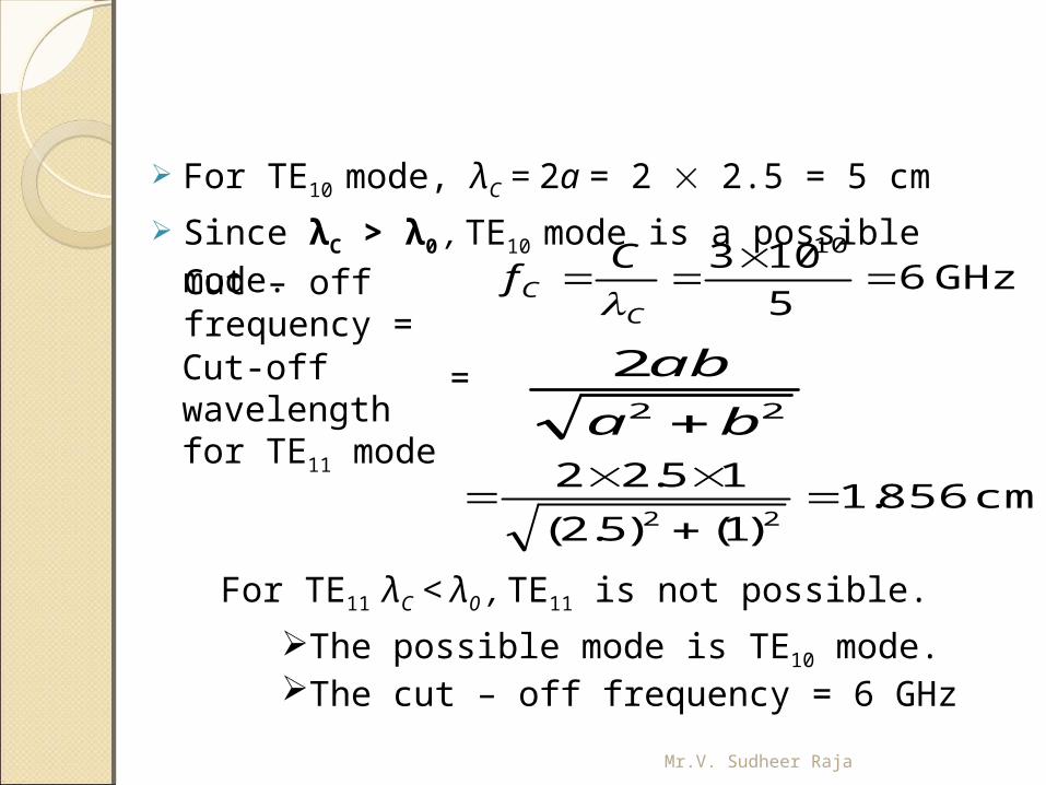
For TE10 mode, λC = 2a = 2 2.5 = 5 cm
Since λC > λ0 , TE10 mode is a possible mode.Cut – off frequency =
GHz65
103 10
C
C
Cf
Cut-off wavelength for TE11 mode
cm856.1)1()5.2(
15.2222
22
2
ba
ab
For TE11 λC < λ0 , TE11 is not possible.
The possible mode is TE10 mode. The cut – off frequency = 6 GHz
=
Mr.V. Sudheer Raja
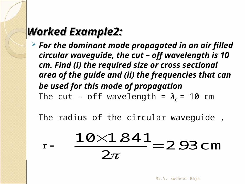
Worked Example2:Worked Example2: For the dominant mode propagated in an
air filled circular waveguide, the cut – off wavelength is 10 cm. Find (i) the required size or cross sectional area of the guide and (ii) the frequencies that can be used for this mode of propagation The cut – off wavelength = λC = 10 cm
The radius of the circular waveguide ,
cm 39.22
841.110
=r
Mr.V. Sudheer Raja
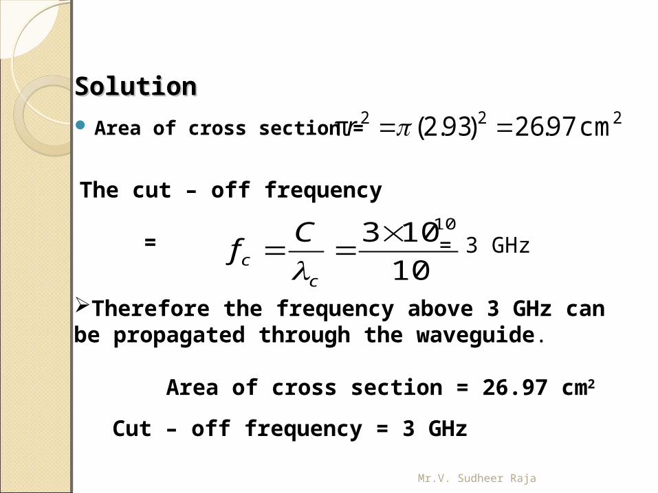
SolutionSolution Area of cross section =
222 cm97.26)93.2(π r
The cut – off frequency
10
103 10
cc
Cf
=
Therefore the frequency above 3 GHz can be propagated through the waveguide.
Area of cross section = 26.97 cm2
Cut – off frequency = 3 GHz
= 3 GHz
Mr.V. Sudheer Raja
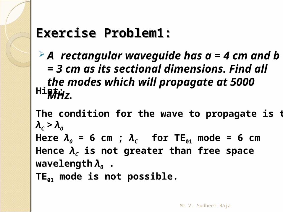
Exercise Problem1:Exercise Problem1: A rectangular waveguide has a = 4
cm and b = 3 cm as its sectional dimensions. Find all the modes which will propagate at 5000 MHz.
Hint:
The condition for the wave to propagate is that λC > λ0
Here λ0 = 6 cm ; λC for TE01 mode = 6 cmHence λC is not greater than free space wavelength λ0 .TE01 mode is not possible.
Mr.V. Sudheer Raja
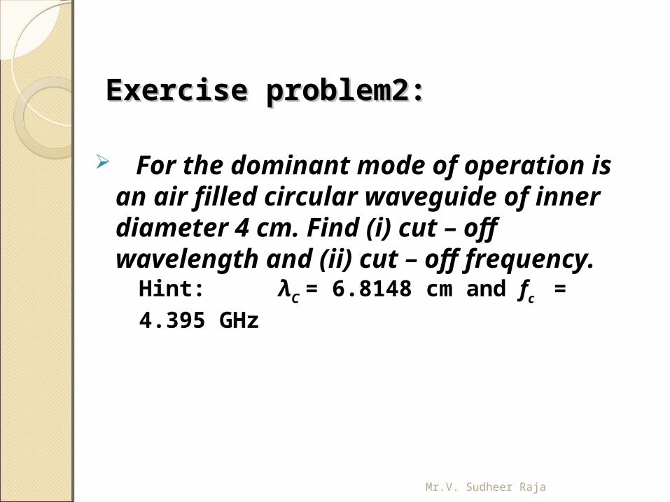
Exercise problem2:Exercise problem2:
For the dominant mode of operation is an air filled circular waveguide of inner diameter 4 cm. Find (i) cut – off wavelength and (ii) cut – off frequency.Hint: λC = 6.8148 cm and fc = 4.395 GHz
Mr.V. Sudheer Raja