Embed Size (px)
Citation preview
1 1
Miniature Motion Energy Harvesters with
Rotating Mechanisms
Eric Yeatman
Department of Electrical and Electronic Engineering
Imperial College London
NIPS Summer School
Erice, July 2012
2 2
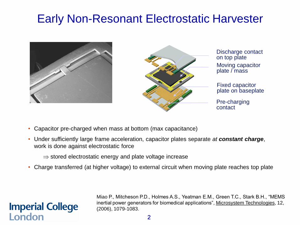
Early Non-Resonant Electrostatic Harvester
Discharge contact on top plate
Moving capacitor plate / mass
Fixed capacitor plate on baseplate
Pre-charging contact
• Capacitor pre-charged when mass at bottom (max capacitance)
• Under sufficiently large frame acceleration, capacitor plates separate at constant charge,
work is done against electrostatic force
stored electrostatic energy and plate voltage increase
• Charge transferred (at higher voltage) to external circuit when moving plate reaches top plate
Miao P., Mitcheson P.D., Holmes A.S., Yeatman E.M., Green T.C., Stark B.H., “MEMS
inertial power generators for biomedical applications”, Microsystem Technologies, 12,
(2006), 1079-1083.
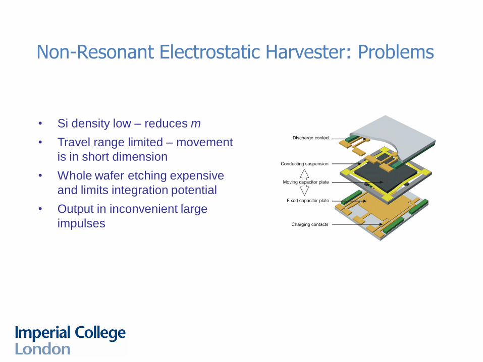
Non-Resonant Electrostatic Harvester: Problems
• Si density low – reduces m
• Travel range limited – movement
is in short dimension
• Whole wafer etching expensive
and limits integration potential
• Output in inconvenient large
impulses
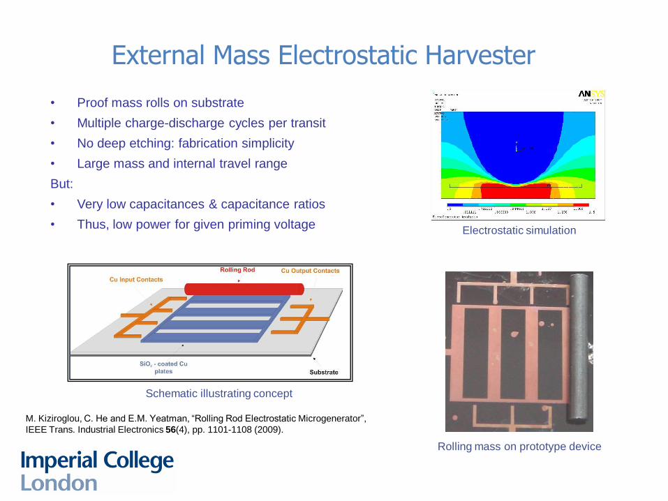
External Mass Electrostatic Harvester
• Proof mass rolls on substrate
• Multiple charge-discharge cycles per transit
• No deep etching: fabrication simplicity
• Large mass and internal travel range
But:
• Very low capacitances & capacitance ratios
• Thus, low power for given priming voltage
Rolling mass on prototype device
Schematic illustrating concept
Electrostatic simulation
M. Kiziroglou, C. He and E.M. Yeatman, “Rolling Rod Electrostatic Microgenerator”,
IEEE Trans. Industrial Electronics 56(4), pp. 1101-1108 (2009).
5 5
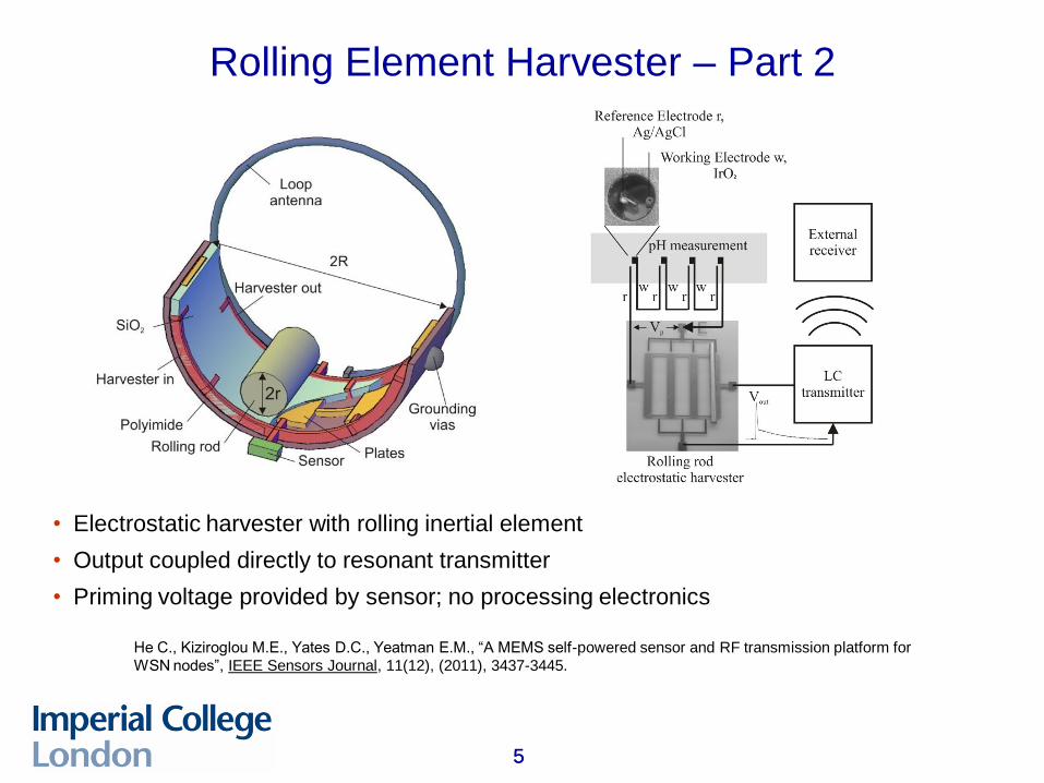
Rolling Element Harvester – Part 2
• Electrostatic harvester with rolling inertial element
• Output coupled directly to resonant transmitter
• Priming voltage provided by sensor; no processing electronics
He C., Kiziroglou M.E., Yates D.C., Yeatman E.M., “A MEMS self-powered sensor and RF transmission platform for
WSN nodes”, IEEE Sensors Journal, 11(12), (2011), 3437-3445.
6 6
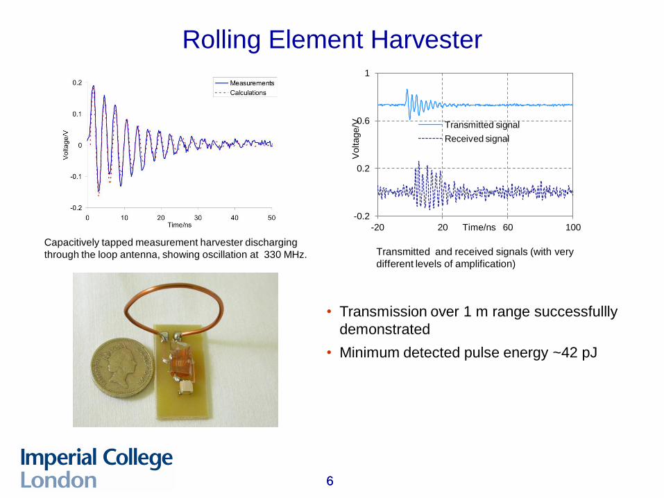
Rolling Element Harvester
• Transmission over 1 m range successfullly
demonstrated
• Minimum detected pulse energy ~42 pJ
-0.2
0.2
0.6
1
-20 20 60 100
Voltage/V
Time/ns
Transmitted signal
Received signal
Capacitively tapped measurement harvester discharging
through the loop antenna, showing oscillation at 330 MHz. Transmitted and received signals (with very
different levels of amplification)
7 7
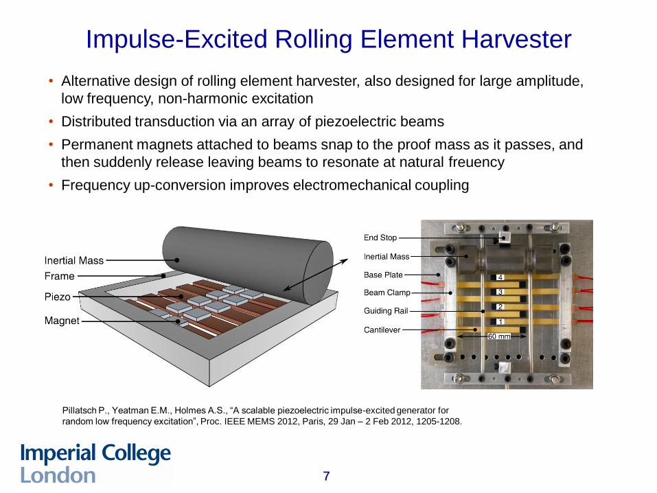
Impulse-Excited Rolling Element Harvester
• Alternative design of rolling element harvester, also designed for large amplitude,
low frequency, non-harmonic excitation
• Distributed transduction via an array of piezoelectric beams
• Permanent magnets attached to beams snap to the proof mass as it passes, and
then suddenly release leaving beams to resonate at natural freuency
• Frequency up-conversion improves electromechanical coupling
Pillatsch P., Yeatman E.M., Holmes A.S., “A scalable piezoelectric impulse-excited generator for
random low frequency excitation”, Proc. IEEE MEMS 2012, Paris, 29 Jan – 2 Feb 2012, 1205-1208.
8 8
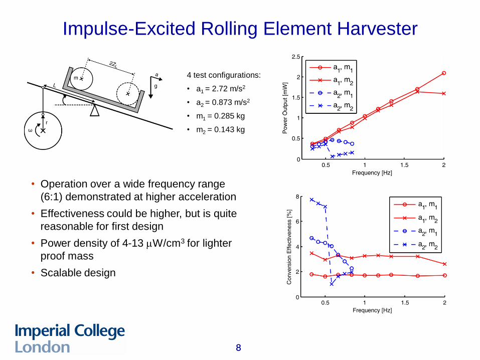
Impulse-Excited Rolling Element Harvester
• Operation over a wide frequency range
(6:1) demonstrated at higher acceleration
• Effectiveness could be higher, but is quite
reasonable for first design
• Power density of 4-13 mW/cm3 for lighter
proof mass
• Scalable design
4 test configurations:
• a1 = 2.72 m/s2
• a2 = 0.873 m/s2
• m1 = 0.285 kg
• m2 = 0.143 kg
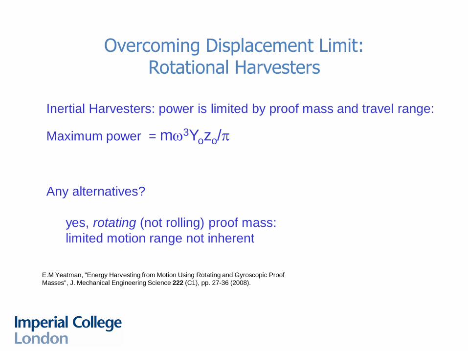
Inertial Harvesters: power is limited by proof mass and travel range:
Maximum power = mw3Yozo/p
Any alternatives?
yes, rotating (not rolling) proof mass:
limited motion range not inherent
Overcoming Displacement Limit: Rotational Harvesters
E.M Yeatman, "Energy Harvesting from Motion Using Rotating and Gyroscopic Proof
Masses", J. Mechanical Engineering Science 222 (C1), pp. 27-36 (2008).
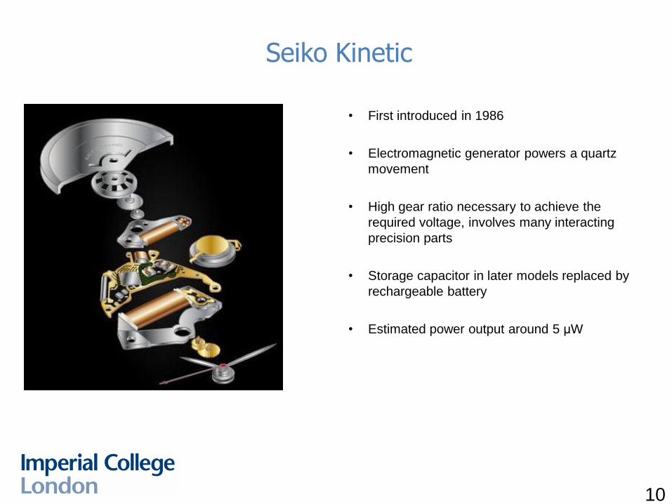
Seiko Kinetic
10
• First introduced in 1986
• Electromagnetic generator powers a quartz
movement
• High gear ratio necessary to achieve the
required voltage, involves many interacting
precision parts
• Storage capacitor in later models replaced by
rechargeable battery
• Estimated power output around 5 μW
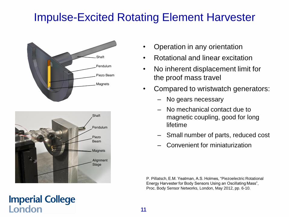
Impulse-Excited Rotating Element Harvester
11 11
• Operation in any orientation
• Rotational and linear excitation
• No inherent displacement limit for
the proof mass travel
• Compared to wristwatch generators:
– No gears necessary
– No mechanical contact due to
magnetic coupling, good for long
lifetime
– Small number of parts, reduced cost
– Convenient for miniaturization
P. Pillatsch, E.M. Yeatman, A.S. Holmes, “Piezoelectric Rotational
Energy Harvester for Body Sensors Using an Oscillating Mass”,
Proc. Body Sensor Networks, London, May 2012, pp. 6-10.
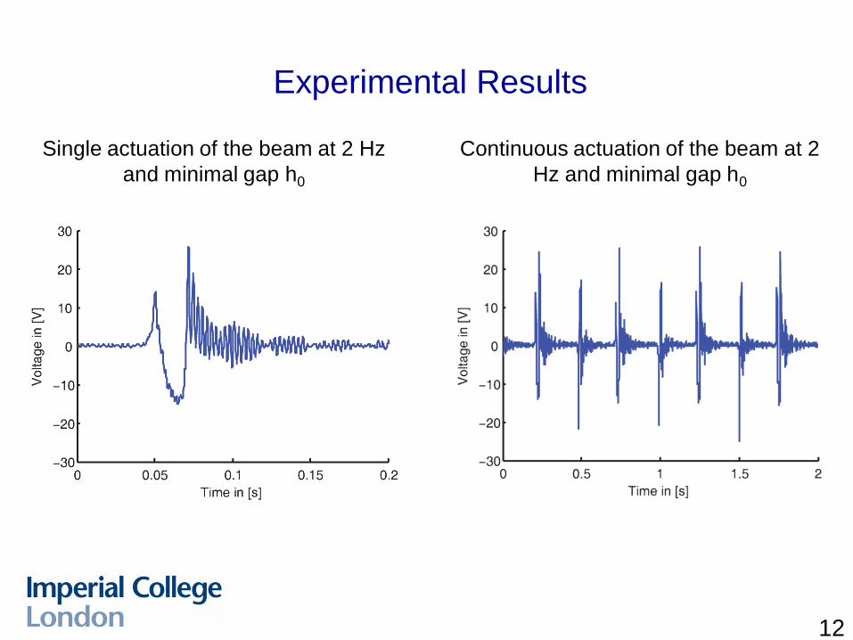
Experimental Results
12
Single actuation of the beam at 2 Hz
and minimal gap h0
Continuous actuation of the beam at 2
Hz and minimal gap h0
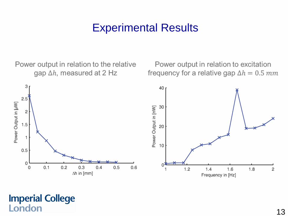
Experimental Results
13
14 14
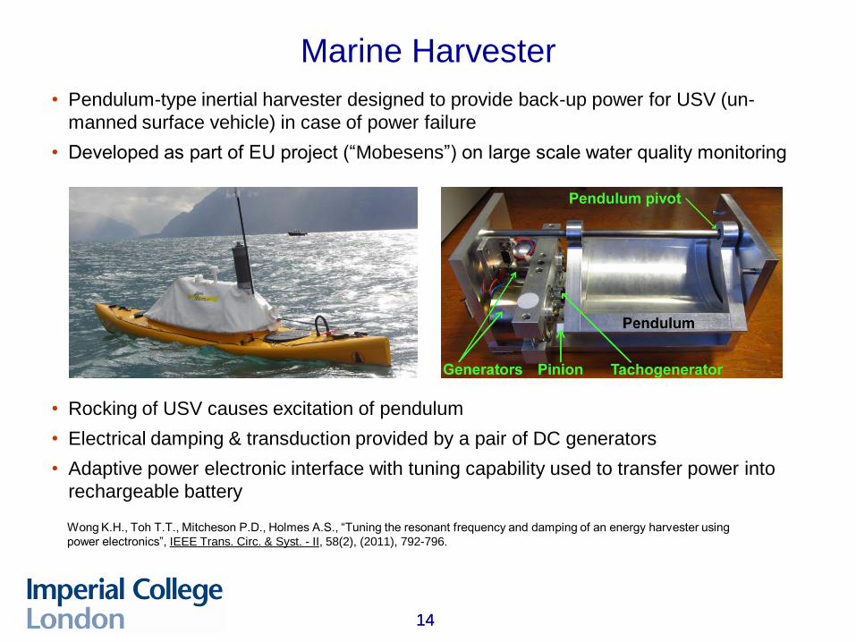
Marine Harvester
• Pendulum-type inertial harvester designed to provide back-up power for USV (un-
manned surface vehicle) in case of power failure
• Developed as part of EU project (“Mobesens”) on large scale water quality monitoring
• Rocking of USV causes excitation of pendulum
• Electrical damping & transduction provided by a pair of DC generators
• Adaptive power electronic interface with tuning capability used to transfer power into
rechargeable battery
Wong K.H., Toh T.T., Mitcheson P.D., Holmes A.S., “Tuning the resonant frequency and damping of an energy harvester using
power electronics”, IEEE Trans. Circ. & Syst. - II, 58(2), (2011), 792-796.
15 15
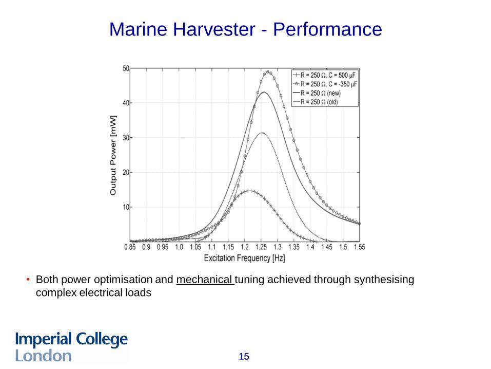
Marine Harvester - Performance
• Both power optimisation and mechanical tuning achieved through synthesising
complex electrical loads
16 16
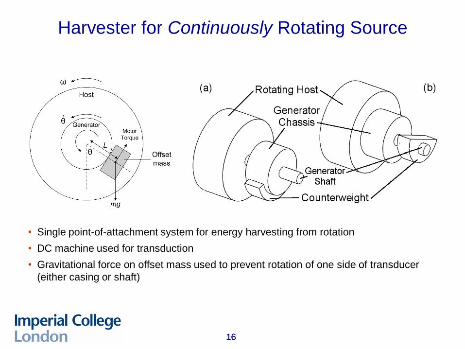
Harvester for Continuously Rotating Source
• Single point-of-attachment system for energy harvesting from rotation
• DC machine used for transduction
• Gravitational force on offset mass used to prevent rotation of one side of transducer
(either casing or shaft)
17 17
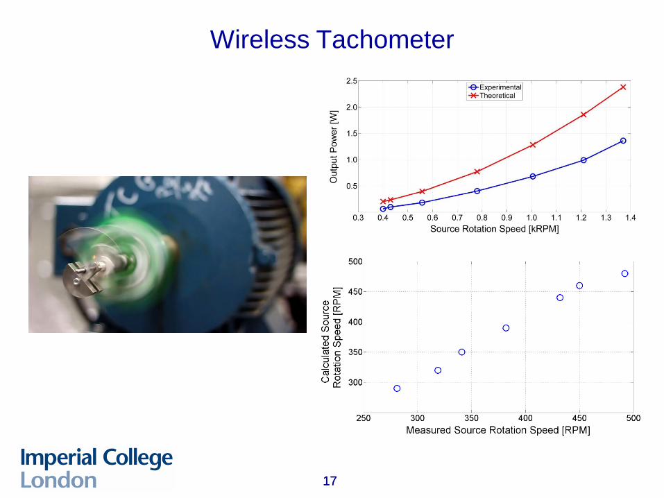
Wireless Tachometer
Maximum power = mw3Yozo/p
Freely rotating mass: can rotate > 360º but can only extract energy
during 180º per half cycle (unless source motion > 360º !)
Any alternatives?
yes, resonant spinning mass
Overcoming Displacement Limit: Rotation Range
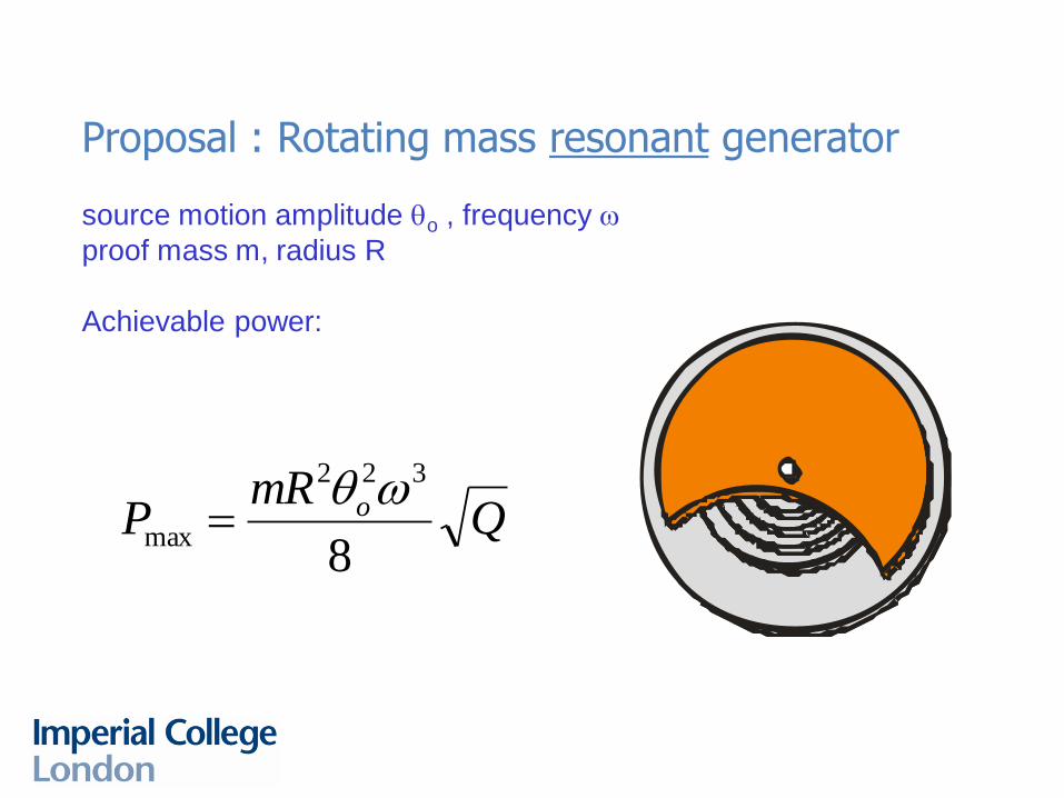
Proposal : Rotating mass resonant generator
source motion amplitude qo , frequency w
proof mass m, radius R
Achievable power:
QmR
P o
8
322
max
wq
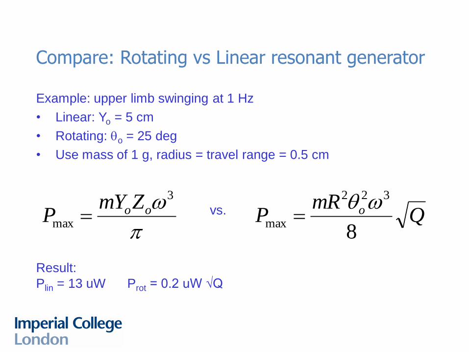
Compare: Rotating vs Linear resonant generator
Example: upper limb swinging at 1 Hz
• Linear: Yo = 5 cm
• Rotating: qo = 25 deg
• Use mass of 1 g, radius = travel range = 0.5 cm
QmR
P o
8
322
max
wq
p
w3
maxooZmY
P vs.
Result:
Plin = 13 uW Prot = 0.2 uW √Q
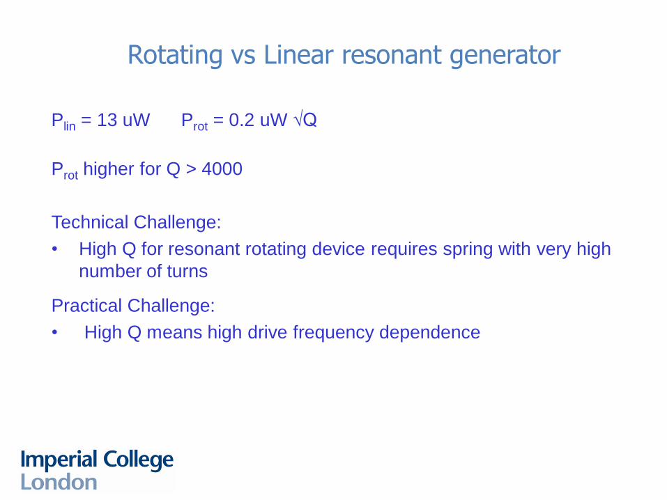
Rotating vs Linear resonant generator
Plin = 13 uW Prot = 0.2 uW √Q
Prot higher for Q > 4000
Technical Challenge:
• High Q for resonant rotating device requires spring with very high
number of turns
Practical Challenge:
• High Q means high drive frequency dependence

How else can rotating motion be used in inertial
generation?
Overcoming the Mass Limit
How else can rotating motion be used in inertial
generation?
What about driving the rotation actively?
Overcoming the Mass Limit
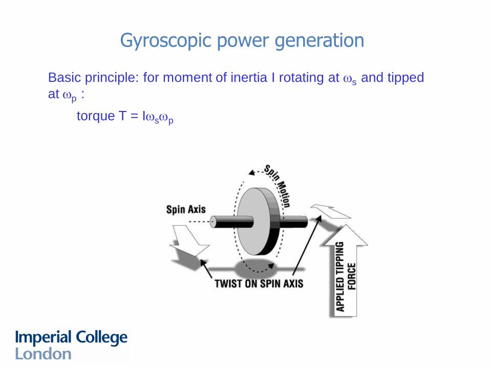
Gyroscopic power generation
Basic principle: for moment of inertia I rotating at ws and tipped
at wp :
torque T = Iwswp
Gyroscopic power generation
Opportunity: power output rises with spin speed
Limitation: need to subtract drive power
• Depends on drive speed
• optimum drive speed thus determined by Q
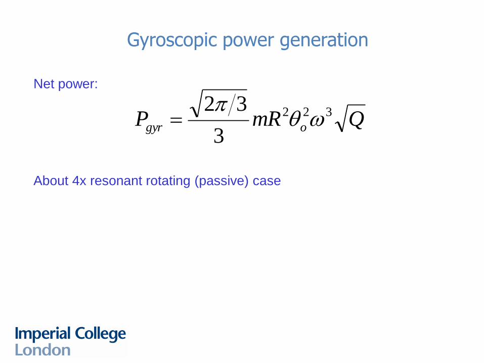
Gyroscopic power generation
Net power:
About 4x resonant rotating (passive) case
QmRP ogyr
322
3
32wq
p
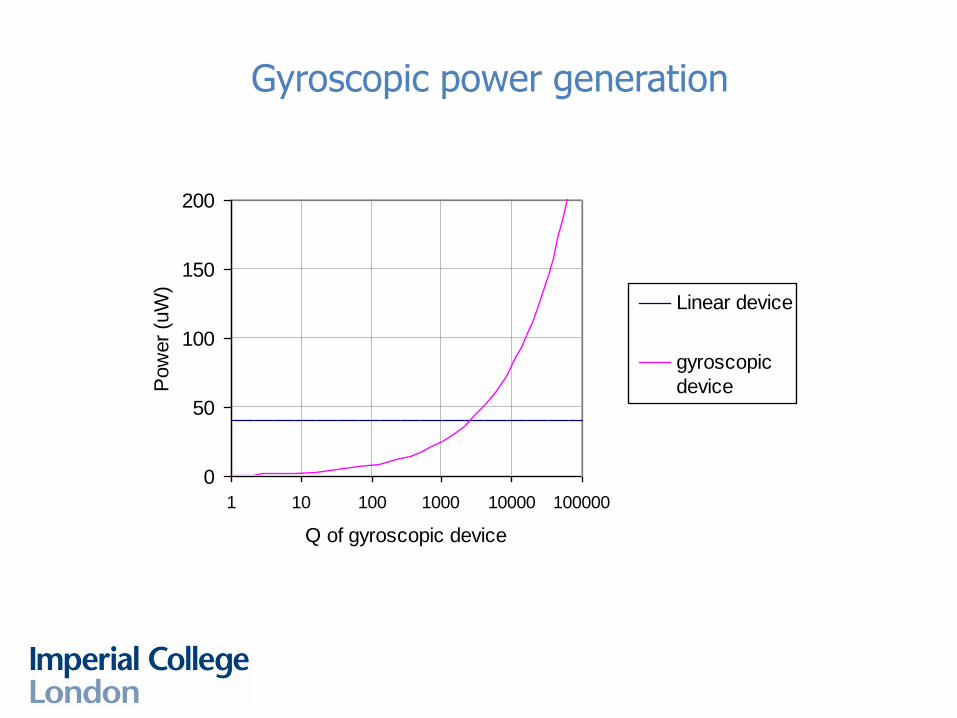
Gyroscopic power generation
0
50
100
150
200
1 10 100 1000 10000 100000
Q of gyroscopic device
Pow
er
(uW
)
Linear device
gyroscopic
device
Gyroscopic power generation
How to implement in MEMS? High quality spinning bearings not really
available.
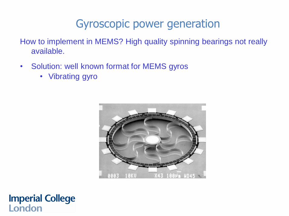
Gyroscopic power generation
How to implement in MEMS? High quality spinning bearings not really
available.
• Solution: well known format for MEMS gyros
• Vibrating gyro
Gyroscopic power generation
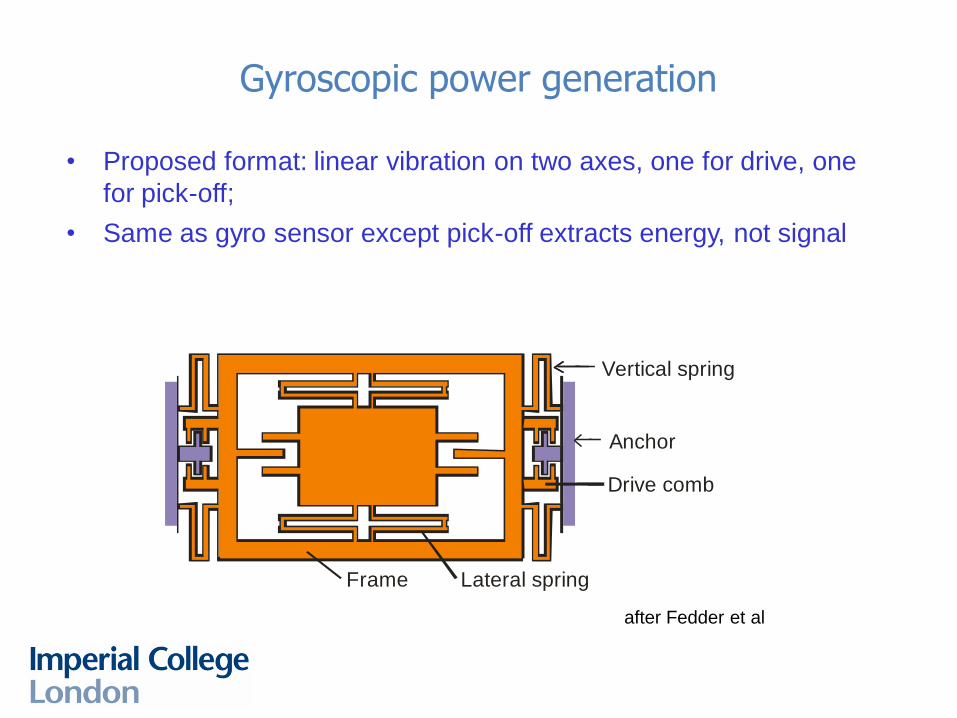
• Proposed format: linear vibration on two axes, one for drive, one
for pick-off;
• Same as gyro sensor except pick-off extracts energy, not signal
Vertical spring
Anchor
Frame Lateral spring
Drive comb
after Fedder et al
31 31
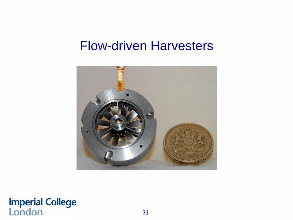
Flow-driven Harvesters
32
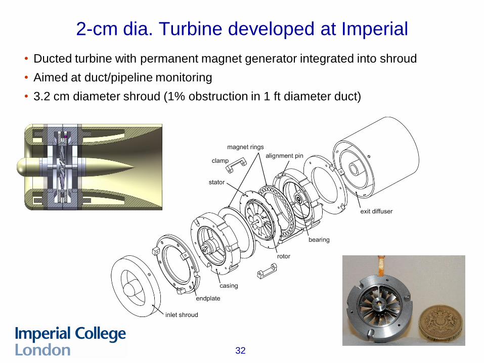
2-cm dia. Turbine developed at Imperial
• Ducted turbine with permanent magnet generator integrated into shroud
• Aimed at duct/pipeline monitoring
• 3.2 cm diameter shroud (1% obstruction in 1 ft diameter duct)
33
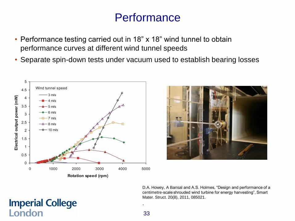
Performance
• Performance testing carried out in 18” x 18” wind tunnel to obtain
performance curves at different wind tunnel speeds
• Separate spin-down tests under vacuum used to establish bearing losses
D.A. Howey, A Bansal and A.S. Holmes, “Design and performance of a
centimetre-scale shrouded wind turbine for energy harvesting”, Smart
Mater. Struct. 20(8), 2011, 085021.
.
34
Prof. Eric Yeatman
Optical and Semiconductor Devices Group
Department of Electrical and Electronic Engineering
Imperial College London
Exhibition Road, London SW7 2BT, UK
http://www3.imperial.ac.uk/opticalandsemidev
Contact