Embed Size (px)
Citation preview
भारत सरकार/ Government of India
व तु मऽंालय / Ministry of Power
कि य व तु ूािधकरण/ Central Electricity Authority ूणाली योजना एवं प रयोजना मू यांकन ूभाग System Planning & Project Appraisal Division
सेवा भवन, आर.के . पुरम, नई द ली ‐ 110066 Sewa Bhawan, R.K. Puram, New Delhi – 110066
No. 51/4/(38th )/SP&PA-2015/731-744 Date: 23-March-2015 Sub: 38th meeting of the Standing Committee on Power System Planning of Southern
Region ‐ Minutes of the meeting
Sir, The 38th meeting of the Standing Committee on Power System Planning of Southern Region was held on 7th March, 2015 in NRPC Committee room, Katwaria Sarai, New Delhi. The Minutes of the meeting are enclosed. The Minutes are available at CEA’s website ( www.cea.nic.in ).
Yours faithfully,
(ूद प जदंल /Pardeep Jindal) िनदेशक (ू यो एवं प म ू)/Director (SP&PA) Division,
(Tel: 011‐26198092, Fax: 011‐26102945) To
1. The Member Secretary, Southern Regional Power Committee, 29, Race Course Cross Road, Bangalore 560 009. FAX : 080‐22259343
2. The Director (Projects), Power Grid Corp. of India Ltd. “Saudamini”, Plot No.2, Sector‐29, Gurgaon 122 001, Haryana. FAX : 95124‐2571932
[ISO : 9001 : 2008]
2
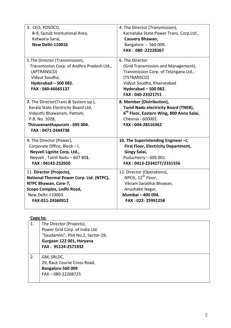
3. CEO, POSOCO, B‐9, Qutub Institutional Area, Katwaria Sarai, New Delhi‐110016
4. The Director (Transmission), Karnataka State Power Trans. Corp.Ltd., Cauvery Bhawan, Bangalore ‐ 560 009. FAX : 080 ‐22228367
5.The Director (Transmission), Transmission Corp. of Andhra Pradesh Ltd., (APTRANSCO) Vidyut Soudha, Hyderabad – 500 082. FAX : 040‐66665137
6. The Director (Grid Transmission and Management), Transmission Corp. of Telangana Ltd., (TSTRANSCO) Vidyut Soudha, Khairatabad Hyderabad – 500 082. FAX : 040‐23321751
7. The Director(Trans & System op.), Kerala State Electricity Board Ltd, Vidyuthi Bhawanam, Pattom, P.B. No. 1028, Thiruvananthapuram ‐ 695 004. FAX : 0471‐2444738
8. Member (Distribution), Tamil Nadu electricity Board (TNEB), 6th Floor, Eastern Wing, 800 Anna Salai, Chennai ‐ 600002. FAX : 044‐28516362
9. The Director (Power), Corporate Office, Block – I, Neyveli Lignite Corp. Ltd., Neyveli , Tamil Nadu – 607 801. FAX : 04142‐252650
10. The Superintending Engineer –I, First Floor, Electricity Department, Gingy Salai, Puducherry – 605 001. FAX : 0413‐2334277/2331556
11. Director (Projects), National Thermal Power Corp. Ltd. (NTPC), NTPC Bhawan, Core‐7, Scope Complex, Lodhi Road, New Delhi‐110003. FAX‐011‐24360912
12. Director (Operations), NPCIL, 12th Floor, Vikram Sarabhai Bhawan, Anushakti Nagar, Mumbai – 400 094. FAX : 022‐ 25991258
Copy to: 1. The Director (Projects),
Power Grid Corp. of India Ltd. “Saudamini”, Plot No.2, Sector‐29, Gurgaon 122 001, Haryana. FAX : 95124‐2571932
2. GM, SRLDC, 29, Race Course Cross Road, Bangalore 560 009 FAX – 080‐22268725
3
MINUTES OF MEETING
Draft-Minutes of 38th Meeting of the Standing Committee on Power System Planning in Southern Region (SCPSPSR) held on 7th March, 2015 at NRPC, Katwaria Saria, New Delhi
1. Introduction
1.1 Chairperson, CEA welcomed the participants and informed that a total of 19 agenda points and two additional agenda items will be discussed in the meeting. He requested Chief Engineer(SP&PA) to apprise the committee on the recent development regarding implementation of transmission projects.
1.2 CE(SP&PA), CEA welcomed the participants and informed the constituents about the schemes awarded through TBCB route and Compressed time Schedule. He stated that following schemes have been allocated to PGCIL under compressed time schedule:
(i) HVDC Bipole link between Western region (Raigarh, Chhattisgarh) and Southern region (Pugalur, Tamil Nadu) (iii) Erection of 220 kV line to Karaikal scheme
He also informed that the said that the “Additional inter-Regional AC link for import into Southern Region i.e. Warora – Warangal and Chilakaluripeta - Hyderabad - Kurnool 765kV link” scheme would be implemented through TBCB route.
He also informed the constituents that MoP has delegated the power for grant
of prior approval u/s 68 of EA 2003 to Chairperson, CEA. Further, the Ministry is also in the process of issuing an order regarding timelines for concept to commissioning of transmission schemes, and according to which, the SCPSP meetings would be held on fixed dates.
With these views he requested Director (SP&PA) to take up agenda items.
1.3 List of participants is given at Annex-I.
1.4 These Minutes may be read along with the Agenda circulated for this meeting.
4
2.0 Confirmation of the minutes of 37th meeting of the Standing Committee
2.1 Director(SP&PA), CEA stated that minutes of the 37th meeting of the Standing Committee on Power System Planning of Southern Region were issued vide. CEA’s letter No. 51/4/(37th)/ SP&PA-2014/ 1729-42 dated 22nd September, 2014. SRLDC gave their observations regarding Vemagiri rearrangement and Hinduja Plant evacuation and additional agenda related to Vemagiri- Khammam- Hyderabad corridor. POSOCO vide their letter No NLDC/Planning/761 dated 24th Sept, 2014 cited a correction in para 12.3 of the minutes regarding 400/230 kV S/S at Tirunelveli Pooling Station. POSOCO suggested ‘one and a half breaker scheme’ instead of ‘double bus scheme for increased reliability’. Accordingly, corrigendum#1 was issued vide CEA letter no 51/4/(37th )/SP&PA-2014/1796-1809 dated 09-October, 2014.
2.2 Transmission Corporation of Andhra Pradesh Ltd(APTRANSCO) vide their letter No CE(IPC&PS)/ SE(PS)/DE(SS<SS) ADE-2/ F.37thSCM/ D.No.156/2014 dated 05.11.2014 have commented that the Cuddapah-Hindupur 400kV (quad) D/c line with 80 MVAr switchable line reactor at both ends may be implemented as ISTS instead of by APTRANSCO. Accordingly, corrigendum#2 was issued vide CEA letter no 51/4/(37th )/SP&PA-2014/2417-30 dated 22-December, 2014.
2.3 TNEB requested to include 2X125 MVAr reactor at Udangudi Power Project Stage-I (2x660MW).
2.4 Accordingly, the minutes of 37th Standing Committee of Power System Planning of Southern Region along with the Corrigendums, as circulated were confirmed.
Further, the scope under Connectivity for Udangudi Power Project Stage-I (2x660MW) of Para 3.8 of the Minutes is now modified as below:
Connectivity for Udangudi Power Project Stage-I (2x660MW):
(i) 400kV DC Quad line to the Udangudi Pooling station.
(ii) 2X125 MVAr, 400kV bus reactor at Udangudi Pooling station.
3.0 Augmentation of Transformer Capacities in SR
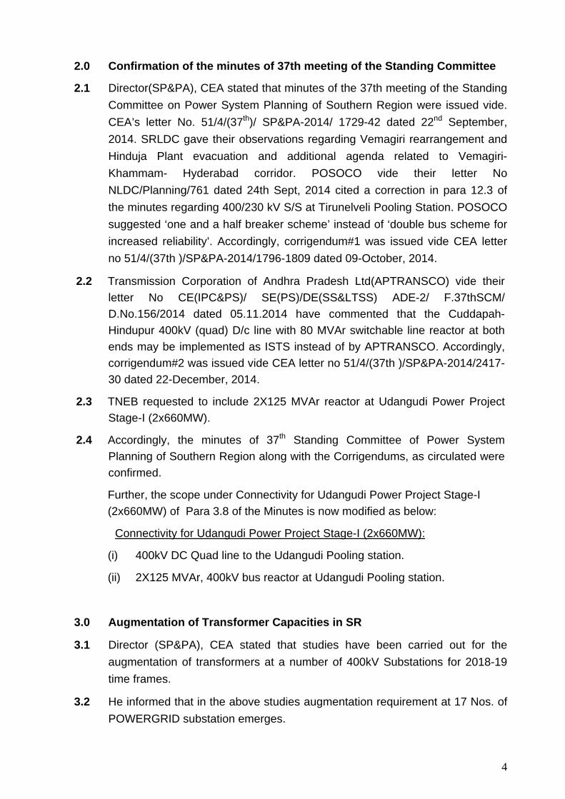
3.1 Director (SP&PA), CEA stated that studies have been carried out for the augmentation of transformers at a number of 400kV Substations for 2018-19 time frames.
3.2 He informed that in the above studies augmentation requirement at 17 Nos. of POWERGRID substation emerges.
5
Sl no
Substation Existing / Approved trf.
Transformer Augmentation
Required
Remarks
1 HYDERABAD 3*315+500=1445 1000 Space not available 2 GAZUWAKA 2x315=630 500 Space not available 3 WARANGAL 2*315+500=1130 500 Space not available 4 MUNIRABAD 2*315=630 500 Can be carried out 5 MYSORE 2*315+500=1130 500 Space not available 6 KOLAR 2*500=1000 500 Space not available 7 NARENDRA 2*500=1000 500 Space not available 8 MADHUGIRI 2*500=1000 500 Can be carried out
9 MUVATTUPUZHA (KOCHIN) 2*315=630 500 Can be carried out
10 PALAKKAD 2*315=630 500 Can be carried out
11 TRICHY 2*315=630 2*500 One unit already
approved. No space for second
12 HOSUR 3*315=945 1000 Space not available
13 PUGALUR 2*315=630 2*500 One already
approved. No space for second
14 ARASUR 2*315=630 500 Can be carried out 15 KARAIKUDI 2*315=630 500 Can be carried out 16 TIRUNELVELI 2*315=630 500 Can be carried out
17 PONDICHERRY 2*315=630 500 Can be carried out
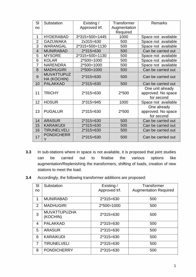
3.3 In sub-stations where in space is not available, it is proposed that joint studies can be carried out to finalise the various options like augmentation/Replenishing the transformers, shifting of loads, creation of new stations to meet the load.
3.4 Accordingly, the following transformer additions are proposed:
Sl no
Substation Existing / Approved trf.
Transformer Augmentation Required
1 MUNIRABAD 2*315=630 500
2 MADHUGIRI 2*500=1000 500
3 MUVATTUPUZHA (KOCHIN) 2*315=630 500
4 PALAKKAD 2*315=630 500
5 ARASUR 2*315=630 500
6 KARAIKUDI 2*315=630 500
7 TIRUNELVELI 2*315=630 500
8 PONDICHERRY 2*315=630 500
6
3.5 COO(CTU),PGCIL stated that transformer augmentation of 500 MVA should be accompanied with two nos. of 220kV bays. They enquired about the requirement of additional 220kV bays by the states.
3.6 Director(T), KPTCL requested to wait till next meeting for the finalization of bays requirement at Munirabad and Madhugiri.
3.7 Director(T&SO), KSEBL stated that the evacuation feeders at 220 kV level from Palakkad and Kochi are to be firmed up before enhancing the ICT capacity. The load growth as projected is not likely to occur at Palakkad and Kochi. Commissioning of Mysore Areakode feeder and HVDC link to Madakkathara are also to be considered in this regard. Hence up-gradation of existing ICT s at Palakkad and Kochi may be considered in the next meeting. PGCIL replied that their Udumalpet- Palakad line is already overloaded and even if Areakod 400kV comes it would not relieve the loading. It was decided that KSEBL would revert back after detailed system studies and evaluation of feasibility of 220kV outlets.
3.8 CEO, POSOCO stated that along with augmentation of transformer, the 220kV outlets should be planned to take benefit of the additional transformation capacity. The states agreed to give their plan to CEA before next meeting of SCPSPSR. He also opined that ratio of fault level to transformation capacity should also be indicated.
3.9 After deliberations augmentation at Arasur, Karaikudi, Tirunelveli and Pondicherry were agreed and for the rest of the four locations, the decision was postponed till the next Standing Committee meeting and based on input provided by KSEB and KPTCL.
4.0 Transmission System for Coastal Tamil Nadu Power Ltd. (4000 MW) Cheyyur UMPP in Kanchipuram of Tamil Nadu
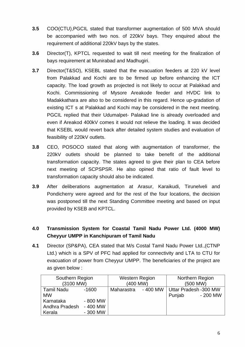
4.1 Director (SP&PA), CEA stated that M/s Costal Tamil Nadu Power Ltd.,(CTNP Ltd.) which is a SPV of PFC had applied for connectivity and LTA to CTU for evacuation of power from Cheyyur UMPP. The beneficiaries of the project are as given below :
Southern Region (3100 MW)
Western Region (400 MW)
Northern Region (500 MW)
Tamil Nadu -1600 MW Karnataka - 800 MWAndhra Pradesh - 400 MWKerala - 300 MW
Maharastra - 400 MW
Uttar Pradesh -300 MW Punjab - 200 MW
7
The project is expected to be commissioned progressively from March 2019 to 2021.
4.2 He informed that the study has been carried out for 2020-21 condition with all generations expected in that time frame and the same has been furnished with the agenda. Considering the quantum of power to be evacuated following 765kV lines have been considered
• Cheyyur UMPP - Thiruvalam 765kV D/c line • Cheyyur UMPP –Salem 765 kV D/c line • Charging of Salem - Madhugiri 765kV D/c line at its rated voltage.
4.3 CE (SP&PA), CEA said that it is learnt that the Government has presently terminated the bidding process for the generation project.
4.4 COO(CTU), PGCIL expressed that as per regulation, they may not be able to hold the application for LTA and only when the applicant withdraws the application then its LTA can be cancelled.
4.5 Chairperson, CEA said that as the Government itself has terminated that bidding process for the generation project, we may keep the transmission planning in abeyance for the time being. The transmission that we plan now may have to be revised when the bidding resumes again.
4.6 It was decided that PGCIL would ask M/s Costal Tamil Nadu Power Ltd, the PFC SPV company to inform latest status of the generation project or if they may like to withdraw their application in view of termination of the bidding process.
5.0 Converting Fixed Line Reactors into Switchable Line Reactors in Over Compensated lines
5.1 Director(SP&PA), CEA stated that due to reduction in line lengths generally after LILO at certain nodes, some lines are being overcompensated with the existing fixed Reactors.
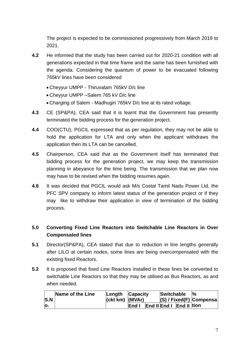
5.2 It is proposed that fixed Line Reactors installed in these lines be converted to switchable Line Reactors so that they may be utilised as Bus Reactors, as and when needed.
Capacity (MVAr)
Switchable (S) / Fixed(F)
S.No.
Name of the Line Length (ckt km)
End I End II End I End II
% Compensation
8
1 Malakaram - Hyderabad-II (upto LILO point) *
27.87 -- 50 -- F 326.1
2 Kurnool – Gooty ** 112.60 -- 50 -- F 80.7
* - LILO of the one circuit of RTPS – Hyderabad(Ghanapur) 400 kV line at Malkaram.
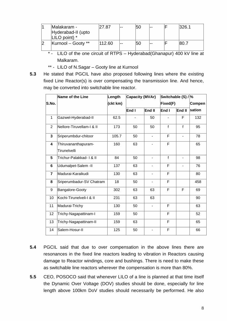
** - LILO of N.Sagar – Gooty line at Kurnool 5.3 He stated that PGCIL have also proposed following lines where the existing
fixed Line Reactor(s) is over compensating the transmission line. And hence, may be converted into switchable line reactor.
Capacity (MVAr) Switchable (S) / Fixed(F)
S.No.
Name of the Line Length (ckt km)
End I End II End I End II
% Compensation
1 Gazwel-Hyderabad-II 62.5 - 50 - F 132
2 Nellore-Tiruvellam-I & II 173 50 50 f f 95
3 Sriperumbdur-chitoor 105.7 50 - F - 78
4 Thiruvananthapuram-
Tirunelvelli
160 63 - F 65
5 Trichur-Palakkad- I & II 84 50 - f - 98
6 Udumalpet-Salem -II 137 63 - F - 76
7 Madurai-Karaikudi 130 63 - F 80
8 Sriperumbadur-SV Chatram 18 50 - F 458
9 Bangalore-Gooty 302 63 63 F F 69
10 Kochi-Tirunelveli-I & II 231 63 63 90
11 Madurai-Trichy 130 50 - F 63
12 Trichy-Nagapattinam-I 159 50 F 52
13 Trichy-Nagapattinam-II 159 63 F 65
14 Salem-Hosur-II 125 50 - F 66
5.4 PGCIL said that due to over compensation in the above lines there are resonances in the fixed line reactors leading to vibration in Reactors causing damage to Reactor windings, core and bushings. There is need to make these as switchable line reactors wherever the compensation is more than 80%.
5.5 CEO, POSOCO said that whenever LILO of a line is planned at that time itself the Dynamic Over Voltage (DOV) studies should be done, especially for line length above 100km DoV studies should necessarily be performed. He also
9
informed that from system operator point of view, they may charge the line without reactor, if the reactor is switchable.
5.6 Director(SP&PA), CEA enquired about status of NGR and the issue of higher voltages across circuit breaker contacts during switching off when these reactors are used as bus reactors. PGCIL explained that the necessary arrangement for bypassing of NGR and Controlled switching of Circuit breaker would be provided at these locations.
5.7 After deliberations, it was decided that the studies will be included to substantiate the requirement of converting fixed Line Reactor(s) into switchable line reactor.
6.0 Reactive compensation at Vemagiri S/S
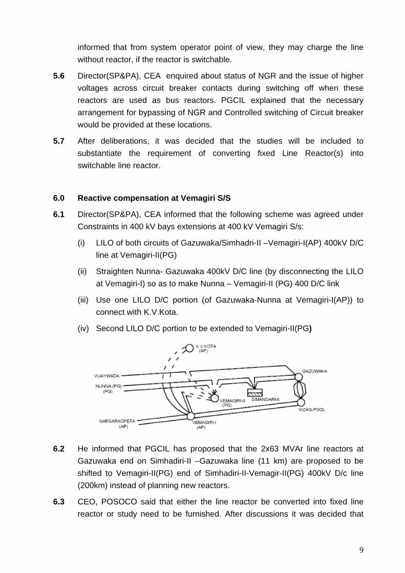
6.1 Director(SP&PA), CEA informed that the following scheme was agreed under Constraints in 400 kV bays extensions at 400 kV Vemagiri S/s:
(i) LILO of both circuits of Gazuwaka/Simhadri-II –Vemagiri-I(AP) 400kV D/C line at Vemagiri-II(PG)
(ii) Straighten Nunna- Gazuwaka 400kV D/C line (by disconnecting the LILO at Vemagiri-I) so as to make Nunna – Vemagiri-II (PG) 400 D/C link
(iii) Use one LILO D/C portion (of Gazuwaka-Nunna at Vemagiri-I(AP)) to connect with K.V.Kota.
(iv) Second LILO D/C portion to be extended to Vemagiri-II(PG)
6.2 He informed that PGCIL has proposed that the 2x63 MVAr line reactors at Gazuwaka end on Simhadiri-II –Gazuwaka line (11 km) are proposed to be shifted to Vemagiri-II(PG) end of Simhadiri-II-Vemagir-II(PG) 400kV D/c line (200km) instead of planning new reactors.
6.3 CEO, POSOCO said that either the line reactor be converted into fixed line reactor or study need to be furnished. After discussions it was decided that
10
though the proposal seem to be in order, however the proposal needs to be substantiated with studies.
7.0 Termination of Narendra-Madhugiri line under TBCB
7.1 Director (SP&PA), CEA informed that as a part of Transmission system for evacuation of power from Kudgi generation(3x800 MW) project, Narendra-Madhugiri 765kV D/c line, charged at 400kV, has been proposed. The transmission line is being developed through Tariff Based Competitive Bidding route and has already been awarded to M/s L&T IDPL. Narendra-Madhugiri 765kV D/c is to be charged initially at 400kV and subsequently would be charged at 765kV. As the line is to be charged at 400kV, presently only 400kV bays are being provided at both ends of line by POWERGRID.
7.2 POWERGRID stated that at a later date when line is to be charged at 765kV, lines shall have to be reoriented for termination at 765kV bus, and the 765kV bays shall have to be provided.
7.3 It was agreed that the provision of 765kV line bays and work required to re-orient the transmission lines to the 765kV bus of PGCIL would be part of ISTS.
8.0 Charging for Kurnool - Thiruvalam 765kV D/c at 400kV
8.1 Director(SP&PA), CEA stated that Kurnool-Thiruvalam 765 kV D/c line of POWERGRID shall facilitate in import of power through Raichur - Sholapur 765 kV D/c lines to the power deficit states of Southern Region. However due to certain unavoidable circumstances there is delay of about 4-5 months in supply of 765kV equipment’s at Thiruvalam end. As an interim measure, till 765kV equipment’s are available, the line was proposed to be charged at 400kV level. CEA vide its letter dated 29/10/2014 has given in-principle clearance to charge Kurnool - Thiruvalam 765kV D/c at 400kV. This line along with Thiruvalam-MTPS Stage-III 400 kV D/c line of TANTRANSCO would help in enhancement of TTC between NEW Grid-SR Grid which shall facilitate in transferring the much required power to the Southern Region states.
8.2 PGCIL has informed that they have charged the line at 400kV on 27-11-2014 and that the line is expected to be charged at 765kV level by March 2015.
8.3 TNEB informed that reactor at Kayathar end of Kayathar- Karaikudi line was not shifted and instead a new reactor was installed at Mettur Stage III end of Thiruvelum- MTPS Stage III 400kV D/C line.
8.4 Members noted.
11
9.0 Re-orientation of Nellore –Vijayawada 400kV D/c line
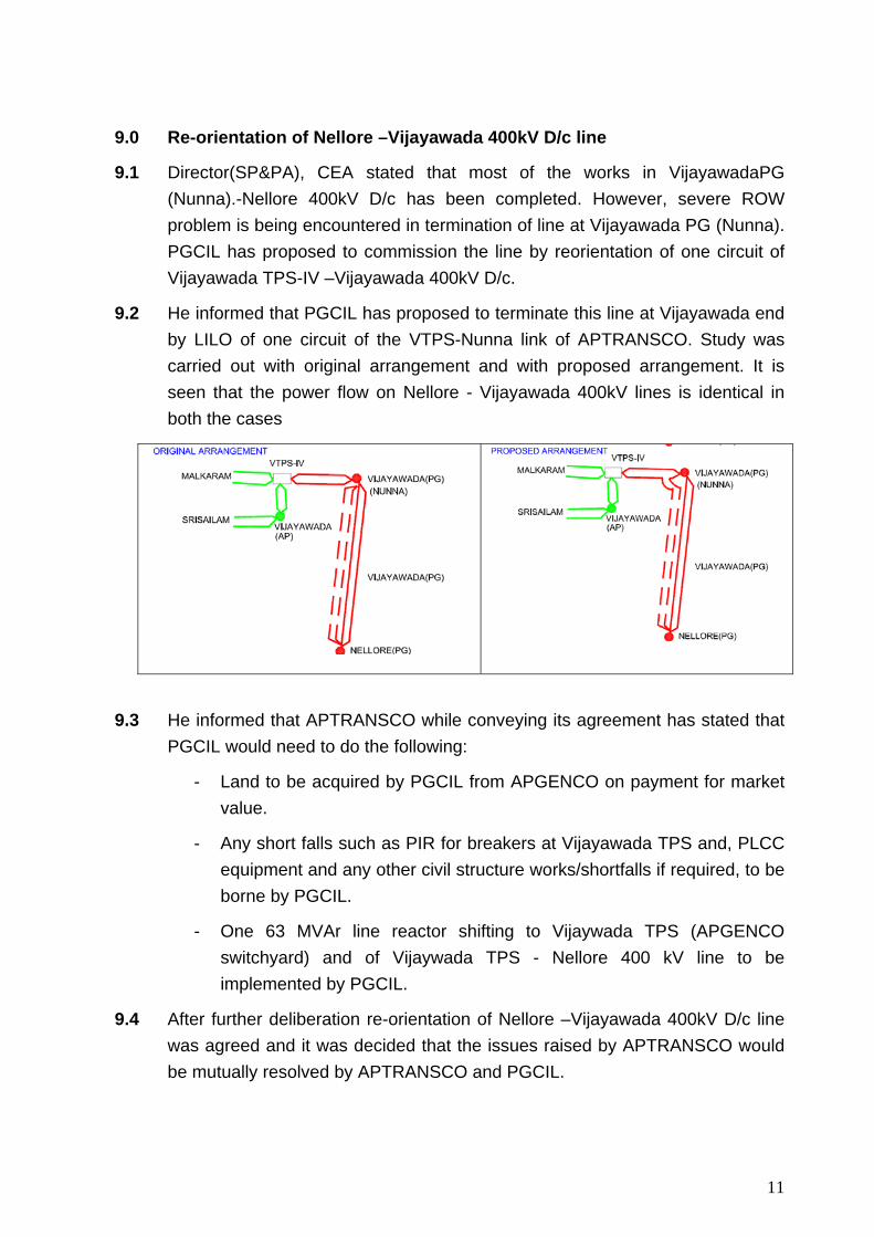
9.1 Director(SP&PA), CEA stated that most of the works in VijayawadaPG (Nunna).-Nellore 400kV D/c has been completed. However, severe ROW problem is being encountered in termination of line at Vijayawada PG (Nunna). PGCIL has proposed to commission the line by reorientation of one circuit of Vijayawada TPS-IV –Vijayawada 400kV D/c.
9.2 He informed that PGCIL has proposed to terminate this line at Vijayawada end by LILO of one circuit of the VTPS-Nunna link of APTRANSCO. Study was carried out with original arrangement and with proposed arrangement. It is seen that the power flow on Nellore - Vijayawada 400kV lines is identical in both the cases
9.3 He informed that APTRANSCO while conveying its agreement has stated that PGCIL would need to do the following:
- Land to be acquired by PGCIL from APGENCO on payment for market value.
- Any short falls such as PIR for breakers at Vijayawada TPS and, PLCC equipment and any other civil structure works/shortfalls if required, to be borne by PGCIL.
- One 63 MVAr line reactor shifting to Vijaywada TPS (APGENCO switchyard) and of Vijaywada TPS - Nellore 400 kV line to be implemented by PGCIL.
9.4 After further deliberation re-orientation of Nellore –Vijayawada 400kV D/c line was agreed and it was decided that the issues raised by APTRANSCO would be mutually resolved by APTRANSCO and PGCIL.
12
10.0 Tapping of Uravakonda- Jammalamadagu D/c Quad line with Gooty –Madhugiri 400kV D/c line:
10.1 Director (SP&PA), CEA informed that Transmission Corporation of Andhra Pradesh Ltd. has proposed to tap Gooty - Madhugiri twin moose D/C ISTS line with their Uravakonda- Kondapur (Jammalamadugu) 400kv Quad moose line for one wind season i.e. from Apr 2015 to Oct 2015.
10.2 He informed that Uravakonda400kV S/s is expected to be commissioned by March’15 for evacuation of about 400MW wind generation expected in the similar time frame. However 400kV lines, envisaged from Uravakonda to Jammalmadugu and Mahaboobnagar substations, would not be completed by this time frame.
10.3 He stated that according to CEA’s safety standard Para 44.6 tapping of transmission line for any purpose is not allowed. He enquired about the commissioning schedules of Uravakonda –Jammalamadugu, Uravakonda - Mehboobnagar, Uravakonda- Hindupur 400kV lines to which APTRANSCO informed the schedule as August 2015, October 2015 respectively for the first two lines while for Uravakonda –Hindupur line tendering process has started.
10.4 Director, APTRANSCO said that they would bunch the D/C line from Uravakonda and connect it with portion of the Gooty –Madhugiri line at the place where the two lines cross.
10.5 PGCIL raised its concern about the effect of tapping after the commissioning of Gooty- Madhugiri 400kV line, to which APTRANSCO replied that they would make LILO of one circuit of the Gooty- Madhugiri 400kV D/C line at Uravakonda.
10.6 PGCIL then cited the issue of metering and transmission charges for use of the ISTS line.
10.7 DGM,SRLDC said that the tapping of Gooty – Madhugiri 400kV line may adversely effect the import capacity from New Grid. He suggested to perform system study for the Monsoon period.
10.8 KSEB said that injection at Gooty will affect the schedule through the 765kV
Raichur – Sholapur link and reduce the import capability of SR. The injection
proposed is only for short duration upto October 2015. However, this is
inclusive of the high demand period in SR. He further said that as per Clause
4.2 ( c ) of IEGC “Any new or modified connections, when established, shall
neither suffer unacceptable effects due to its connectivity to the ISTS nor
impose unacceptable effects on the system of any other connected User or
13
STU”. Therefore, when power is injected to Gooty transmission system, it will
adversely affect the import of power from WR, hence the proposal cannot be
accepted by KSEB.
10.9 KPTCL suggested that tapping the said line is in fact direct injection of 400MW at Gooty.
10.10 After further deliberations, it was decided that joint studies including SRPC, SRLDC, PGCIL and CEA would be performed and the issue would be re-discussed in the next SCPSPSR.
11.0 YTPS- Providing start-up power for Boiler light up and commissioning activities of unit 1:
11.1 Director(Trans), KPTCL informed that 100 MVA start up power would be required to start boiler light up and other commissioning activities of Yermarus TPS. KPTCL also informed that EPC contract has been awarded for executing work of LILO’ing the existing SC line between RTPS and Davanagere to facilitate drawl of power at 400kV level. The said LILO line crosses RTPS-Gooty 400kV Quad D/c line at a distance of 4.5 km from YTPS. Therefore, KPTCL has requested for permission for tapping/LILO’ing of RTPS-Gooty 400kV Quad D/c line, owned by PGCIL.
11.2 Director(SP&PA), CEA said that Tapping/LILO’ing of RTPS-Gooty 400kV Quad D/c line for start up power may have adverse implication on TTC and ATC and also involves commercial issues, metering, reduction of dispatch at Raichur TPS etc.
11.3 DGM, SRLDC said that the issue of Tap Connection from Raichur New-Gooty line for Yermaras startup cannot be agreed due to reliability risk and Protection issues and commercial constraints as well.
11.4 Director(SP&PA), CEA also said that presently one of the main constraints in import of power is loading on Gooty-Neelmangla and Gooty- Somanhalli lines.
11.5 KPTCL informed that as Edlapur TPS is not coming in the near future therefore, Yermarus to Gulbarga 400kV line is not taken up. He also said that they have carried out the studies and the result shows that 800 MW of power can be pumped without any constraints except issue of fault level at Raichur 220kV bus. He informed that the work at Bellary PS has been started and the transmission line from Yermarus to Bellary Pool would take another 24 months.

14
11.6 KSEBL opined that as requested by KPTCL, only start up power may be
allowed to draw from this for the commissioning activities and no injection from
YTPS should be allowed in ISTS without commissioning of their complete
evacuation system. The injection of power from YTPS reduces the import
capability of SR. As per Clause 4.2 ( c ) of IEGC “Any new or modified
connections, when established, shall neither suffer unacceptable effects due to
its connectivity to the ISTS nor impose unacceptable effects on the system of
any other connected User or STU”. Further, as per Clause 8 . 6 of CERC
connectivity regulations “connectivity does not mean that the utility can inject
power” KPTCL may avail start up power through the temporary LILO
arrangement. However, for injection of power the originally planned ATS has to
be in place.
11.7 After further deliberations, it was decided that joint studies including SRPC,
SRLDC, PGCIL and CEA would be performed and the issue would be re-
discussed in the next SCPSPSR. This can be taken up along with studies of
Uravakonda as mentioned above in these minutes.
12.0 Provision of space at various substations of POWERGRID
12.1 Director (SP&PA), CEA informed that TANTRANSCO has approached POWERGRID for execution of line bays at POWERGRID substations, agreed during the 37th Standing committee meeting of Southern Region held on 31/7/2014 :
• Kayathar – Koilpatty(PG) (Tuticorin Pooling point) 400kV DC • Kamuthi – Karaikudi(PG) 400kV D/c • Ariyalur – Thiruvalam(PG) 765kV D/c • Two no of 230kV Bays at Arasur • Two no of 230kV Bays at Shoolagiri (Hosur) • One no of 230kV Bays at Abhishekpatty
12.2 After discussions it was agreed that termination of the line from Kayathar may be considered at Tirunelvelli(PG) in place of Koilpatty(PG).
12.3 It was also agreed that after provision of above bays at Karaikudi, no further space would be available for any future line bays at Karaikudi 400kV. The bays for Thiruvalam(PG) 765kV line can be accommodated.
12.4 It was also decided that the bays for Abhishekpatty 230kV line can be
15
accommodated. Further it may be mentioned after provision of above bays no further space would be available for future line bays at Arasur 230kV.
12.5 At Shoolagiri (Hosur) 2nos of 230 kV line bays can be accommodated.
13.0 Evacuation of SEPC IPP(1x525 MW) –Proposed by TNEB:
13.1 SE, TNEB informed that M/S SPIC Electric Power Corporation Private Ltd (SEPC) has proposed to establish 1X525 MW power plant in Tuticorin as an IPP. To evacuate power from this project, TNEB has proposed following transmission system:
“400kV D/C line to the proposed Ottapidaram 400/230-110kV substation ”.
He said TNEB had informed that the earlier envisaged Udangudi projects (2x660 MW+ 1x800 MW) are being reviewed.
13.2 Director(SP&PA), CEA said that during 37th SCPSPSR, following transmission system was agreed for Udangudi projects:
a. 400kV D/C Quad line to the Kayathar 400kV S/S. b. 400kV D/C Quad line to the proposed Samugarengapuram 400/230-110
kV S/s c. 400kV D/C Quad line to the proposed Ottapidaram 400/230-110 kV S/s.
13.3 SE, TANGEDCO informed that Udangudi Phase-II is dropped as of now. Udangudi Phase-II and Phase-III will come later and their evacuation would be planned at 765kV level. He said that since the evacuation scheme of Udangudi is approved for the entire capacity of 2X660 MW+1X800 MW, SEPC of 1X525 MW may be accommodated in already approved evacuation system of Udangudi project taking the capacity to 2X660 MW+ 1X 525 MW.
13.4 MS, SRPC pointed out that the change in bus voltages are not exhibited in the studies furnished by TANGEDCO. Director(SP&PA), CEA said that in the load flow results sent by TNEB there is overloading in the Kanarpatti – Tirunelveli 400kV line.
13.5 After deliberation, following was decided
i) Prima-facie the transmission system that was earlier agreed for Urangudi Stage I and II may be sufficient to evacuate power from Udangudi 2x660 MW and SEPC 1x525 MW.
ii) TANGEDCO will furnish fresh studies.
13.6 Further CEA urged that TNEB should comply with the regulations of TNERC while planning and implementing the above transmission system. Specially
16
they should comply with “(i) Tamil Nadu Electricity Grid Code dated 19.10.2005 and its amendment from time to time, (ii) Tamil Nadu Electricity Regulatory Commission-intra-State Open Access Regulations 2005 and its amendment from time to time, (iii) Grid connectivity and intra-State Open Access Regulations 2004 and its amendment from time to time of TNERC and its amendments from time to time. TNEB would also ensure that they would follow the “Technical standards for connectivity to the grid Regulation 2007” of Central Electricity Authority and its amendments from time to time while planning and implementing the above transmission system
14.0 Modifications for the Pulianthope 400/230kV S/s:
14.1 Director (SP&PA), CEA stated that the following scheme was approved for Pulianthope 400/230kV S/s during 37th SCPSPSR:
“400kV D/C Quad line from the proposed North Chennai Pooling Station and 400kV D/C line from Manali 400/230-110kV S/s”
14.2 SE, TANGEDCO stated that to cater the future load demand of Chennai city Pulianthope 400/230kV S/s has been proposed. The North Chennai Pooling Station may take some time to materialize, thus 400 kV SC line is proposed from North Chennai Stage II power plant to Pulianthope as a temporary measure.
14.3 Director (SP&PA), CEA suggested 400 kV DC line may be erected from North Chennai Stage II power plant to Pulianthope so that the same could be used subsequently.
14.4 MS, SRPC pointed out that no load flow has been furnished for the changed scheme of Pulianthope 400/230kV S/s, by TANGEDCO.
14.5 After deliberation, it was decided that TANGEDCO will furnish the studies considering 400kV D/C line from North Chennai Stage II power plant to Pulianthope. The studies will also show the complete 220kV and above transmission network in and around Chennai area under various operating scenarios.i.e peak, off peak, low wind, high wind etc.
14.6 Further CEA urged that TNEB should comply with the regulations of TNERC while planning and implementing the above transmission system. Specially they should comply with “(i) Tamil Nadu Electricity Grid Code dated 19.10.2005 and its amendment from time to time, (ii) Tamil Nadu Electricity Regulatory Commission-intra-State Open Access Regulations 2005 and its amendment from time to time, (iii) Grid connectivity and intra-State Open Access Regulations 2004 and its amendment from time to time of TNERC and its
17
amendments from time to time. TNEB would also ensure that they would follow the “technical standards for connectivity to the grid Regulation 2007 of Central Electricity Authority and its amendments from time to time while planning and implementing the above transmission system
15.0 New 400kV Load Substation at Usilampatty
15.1 Director (SP&PA), CEA stated that TANTRANSCO has proposed 400kV load substation at Usilampatty with the following connectivity:
a. 400kV D/C connectivity with Kamuthi 400 kV S/s. b. 400kV D/C connectivity with Thappagundu 400 kV S/s.
15.2 SE, TANGEDCO stated that 400kV Load Substation at Usilampatty is not needed as of now, he requested 400kV Usilampatty S/s to be deferred.
16.0 Edayarpalayam 400/230-110kV S/s under the scope of TANTRANSCO:
16.1 Director (SP&PA), CEA stated that during the 37th SCPSPSR held on 31st July, 2014, the following scheme was agreed under The scheme - “ HVDC Bipole link between Western region (Raigarh, Chhattisgarh) and Southern region (Pugalur, Tamil Nadu) :
(i) Raigarh(HVDC Stn) – Pugalur (HVDC Stn) 6000 MW HVDC bipole
(ii) Establishment of Raigarh HVDC Stn with 6000 MW HVDC terminals
(iii) Establishment of Pugalur HVDC Stn with 6000 MW HVDC terminals (or Alternatively: (i) with Pugalur HVDC Stn with 4000 MW terminal, and (ii) Madakkathara, in Kerala HVDC Stn with 2000 MW terminal and inter-connection with existing 400kV AC S/S at Madakkathara)
(iv) Raigarh HVDC Station – Raigarh(Existing) 400kV (quad) 2xD/c lines (or with bay extension)
(v) Pugalur HVDC Station – Pugalur (Existing) 400kV (quad) D/c line.
(vi) Pugalur HVDC Station – Arasur 400kV (quad) D/c line with 80 MVAr switchable line reactor at Arasur end.
(vii) Pugalur HVDC Station – Thiruvalam 400kV (quad) D/c line with 80 MVAr switchable line reactor at both ends.
18
(viii) Pugalur HVDC Station – Edayarpalayam 400 kV (quad) D/c line with 63 MVAr switchable line reactor at Edayarpalayam end.
(ix) Edayarpalayam – Udumalpet 400 kV (quad) D/c line.
(x) Establishment of 400/220kV substation with 2x500 MVA transformers at Edayarpalayam and 2x125 MVAr bus reactors.
In respect of above TANGEDCO has proposed establishment of Edayarpalyam 400/230-110 kV substation will be under the scope of TANTRASCO.
16.2 SE, TANGEDCO stated that for establishment of Edayarpalyam S/s, land has been purchased and the tendering work is under progress and the establishment of Edayarpalyam 400/230-110 kV substation will be under the scope of TANTRASCO. Also, there is no scope for 400kV bay extension at Udumalpet S/s as earlier communicated by PGCIL. Therefore, TANGEDCO has suggested that Udumalpet- Anikadavu 400kV S/c line may be LILOed at Edayarpalyam S/s. Thus TANGEDCO, has requested following works under their scope:
a. LILO of Udumalpet- Anikadavu 400kV S/c line at Edayarpalyam S/s. b. Establishment of 400/230-110 kV substation with 2x500MVA transformer
at Edayarpalyam and 2x125 MVAr bus reactors.
16.3 PGCIL informed that the space for bays at 400kV Udumalpet S/s is available and 400kV bays for Edayarpalyam- Udumalpet line can be accommodated. COO(CTU), PGCIL stated that delay in establishment of Edayarpalyam 400/230-110 kV substation and Edayarpalyam- Udumalpet line would effect the dispersal of power from Pugalur HVDC and the power may be bottled up.
16.4 In this regard it was suggested that if there is delay in commissioning of Edayarpalyam S/S , the Pugalur- Edayarpalyam line can be connected with Edayarpalyam- Udumalpet bypassing Edayarpalyam for the interim period.
16.5 After deliberations, following was decided:
i) Following will be in the scope of TANTRANSCO/TANGEDCO:
a. Establishment of 400/230-110 kV substation with 2x500MVA transformer at Edayarpalyam and 2x125 MVAr bus reactors
(The LILO of Udumalpet- Anikadavu 400kV S/c line at Edayarpalyam S/s is dropped for the time being in view of availability of bays at Udumalpet and the Edayarpalyam – Udumalpet 400kV D/C line, as in the scope of PGCIL).
19
ii) Edayarpalyam- Udumalpet D/C line would remain in the scope of PGCIL as ISTS
iii) TANGEDCO will commission Edayarpalyam S/S in the time frame matching with the requirement of Raigarh- Pugalur HVDC system.
iv) PGCIL will prepare a list of all the existing, under construction 400kV and above substations in SR indicating the number of transformers, reactors, lines, bays occupied, space for future bays for the 765kV, 400kV and 220kV buses. The format for this information may be decided in consultaion with CEA. Similar list may be prepared by other state also for their network. This list would be helpful for planning future transmission systems.
17.0 Construction of 400kV Quad D/C line from UPCIL (Karnataka) to Kasargod( Kerala).
17.1 Director (SP&PA), CEA stated that during the 35th meeting of SCPSPSR the following scheme was discussed and agreed:
Mangalore(Udipi PCL) – Kasargode – Kozhikode 400kV Link
(i) Mangalore(Udipi PCL) – Kasargode, 400kV quad D/c line
(ii) Kasargode – Kozhikode(Areacode), 400kV quad D/C line
(iii) Establishment of 2x500 MVA, 400/220kV GIS substation at Kasargode
17.2 In the 31st Empowered Committee recommended the schemes for implementation through TBCB subject to the commitment from the Kerala Government that the land compensation only for Right of Way (RoW) for the tower footing area will be paid, instead of the entire corridor. EC also suggested that firm commitment from UPCL for providing 400 kV bays at Mangalore (UPCL) switchyard may be obtained.
17.3 Director (SP&PA), CEA further said that UPCL has communicated the following:
“a) UPCL facility do not have any surplus land where 2 nos. of 400 kV bays can be erected as desired by you.
b) Under the provision of Power Purchase Agreement entered into between UPCL and ESCOM’s of Karnataka, UPCL and Punjab State Power Corporation Limited, Punjab, power is sold to the Buyers ex our switchyard and transmission facility is the responsibility of the Buyers.
20
c) Any additional Capital expenditure required to be incurred by UPCL needs to be approved by the Buyers as per the provisions of Power Purchase Agreement referred to above.
17.4 He informed that during site visit to UPCL generation switchyard, it was observed that there is space for additional two nos. of 400 kV line bays. These line bays can be constructed by extending the existing generation switchyard and dismantling some of the civil structures for creating gantry for the proposed 400 kV DC transmission line. During this visit it was also observed that the route from Kozikode to Kasargode has a thick plantation of coconut, rubber and beetle nut trees. Building transmission lines having sufficient clearance over and above these tall trees would require high rise transmission towers or cutting of these trees under the shadow of transmission lines
17.5 PGCIL said that these bays can be built as ISTS on Deposit work basis and there will not be any tariff impact on Karnataka DISCOMs because of these bays.
17.6 KSEB informed that the route between UPCL to Kasargode is comparatively better for laying transmission line.
17.7 Director(Trans),KPTCL said that the proposed 400 kV DC line to link UPCL to Kasargod may not serve the purpose of strengthening S1-S2 corridor. KPTCL further observed that since UPCL is an ISGS with 90% share of Karnataka, with the construction of 400kV line from UPCL to Kasargode, the 400kV D/C line from UPCL to Hasan will be under utilized. Also, Manglore( Udupi PCL)- Kasargod, 400kV D/C Quad line would not relieve S1-S2 congestion since the upstream 400kV lines beyond Hassan are not having capacity.
17.8 KSEBL informed that once the Kasaragod substation is commissioned adjacent to 220kV substation, Mylatty where land is available, the Kasaragod – Areakode portion can be constructed by extending the RoW of the existing 220kV line and constructing 400/220kV multi circuit multi voltage line. KSEBL do not expect much difficulty in extending the RoW to that of 400kV requirement.
17.9 KPTCL wanted more time and informed that their views will be communicated within two weeks after getting the views of the ESCOMs also.
17.10 It was decided that implementation of the UPCL- Kasargode 400kV D/C line can be initiated after considering views of Karnataka ESCOMS, if communicated within a month.
18.0 Start up power requirement of under construction NCC PPL Power Plant.
21
18.1 Director (SP&PA), CEA informed that as per NCC Power Projects Limited(NCCPPL) the NCCPPL (2X660MW) and Thermal Powertech Corporation India Ltd(2X660MW) (TPCIL) are geographically located adjacent to each other. The evacuation system for TPCIL (TPCIL- Nellore 400kV (QUAD)D/C) is already commissioned in Aug,2013.. They have informed that TPCIL is expected to commission in December, 2014 and NCCPPL by the end of 2015. NCCPPL- Nellore 400kV D/C (Quad) line, to be built by PGCIL, is expected to commission in Dec, 2015. However, back charging of 400kV switchyard of NCCPPL is expected in May, 2015. As a solution, NCCPPL have proposed LILO of one of the existing TPCIL- Nellore 400kV D/C line at NCCPPL bus bar to meet the start up power requirement.
18.2 COO(CTU), PGCIL informed that TPCIL- Nellore 400kV D/C line and NCCPPL- Nellore 400kV D/C (Quad) line would cross each other at one point. He suggested that PGCIL can construct NCCPPL- Nellore 400kV D/C (Quad) line from NCCPL switchyard upto this meeting point and connect it with one circuit of TPCIL- Nellore 400kV D/C line.
18.3 The above was agreed.
19.0 Cost impact of new and ongoing transmission schemes in Southern Region
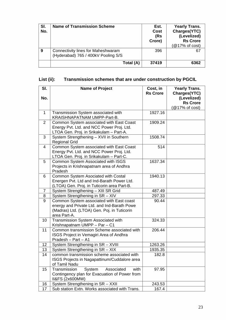
19.1 Director (SP&PA), CEA informed that during the 37th Meeting of the Standing Committee on Power System Planning in Western Region held on 5.9.2014, it was decided that the tentative cost of new schemes would be included in the agenda/ minutes. In this meeting, the WR constituents have also expressed that it would be prudent if impact of new schemes on the transmission tariff is indicated in the agenda/minutes of the meeting. Accordingly the estimated costs of various transmission schemes were given in the agenda. This includes (i) list of transmission schemes that were discussed in the recent meetings of the Empowered Committee, (ii) list of schemes under construction by PGCIL and (iii) list of schemes that were awarded through TBCB and which are under construction.
19.2 COO (CTU), PGCIL observed that there is quiet a variance per unit/per km cost of the transmission elements as given in the agenda and the cost of some of the schemes were on higher side. She also observed that the comparison of the levellised YTC with the levellized YTC as per regulated tariff mechanism does not reflect the true picture and therefore may be avoided. She expressed that this difference may be due to unreasonable cost estimates and also because of the fact that the schemes which are being implemented through
22
TBCB had only transmission line elements and no Substation elements. The levellized tariff for substation and transmission lines is different.
19.3 CE(SP&PA), CEA said that the cost were based on CERC cost benchmarking(2010) as base cost and the costs Matrix as developed by the “cost committee” consisting of CEA, PGCIL, RECTPCL and PFCCL and these are tentative costs. He further informed that CEA is collecting the cost data from states and manufacturers and the cost matrix is being reviewed. Moreover, CERC benchmark cost does not include 765kV D/c and HVDC lines/terminal costs etc.
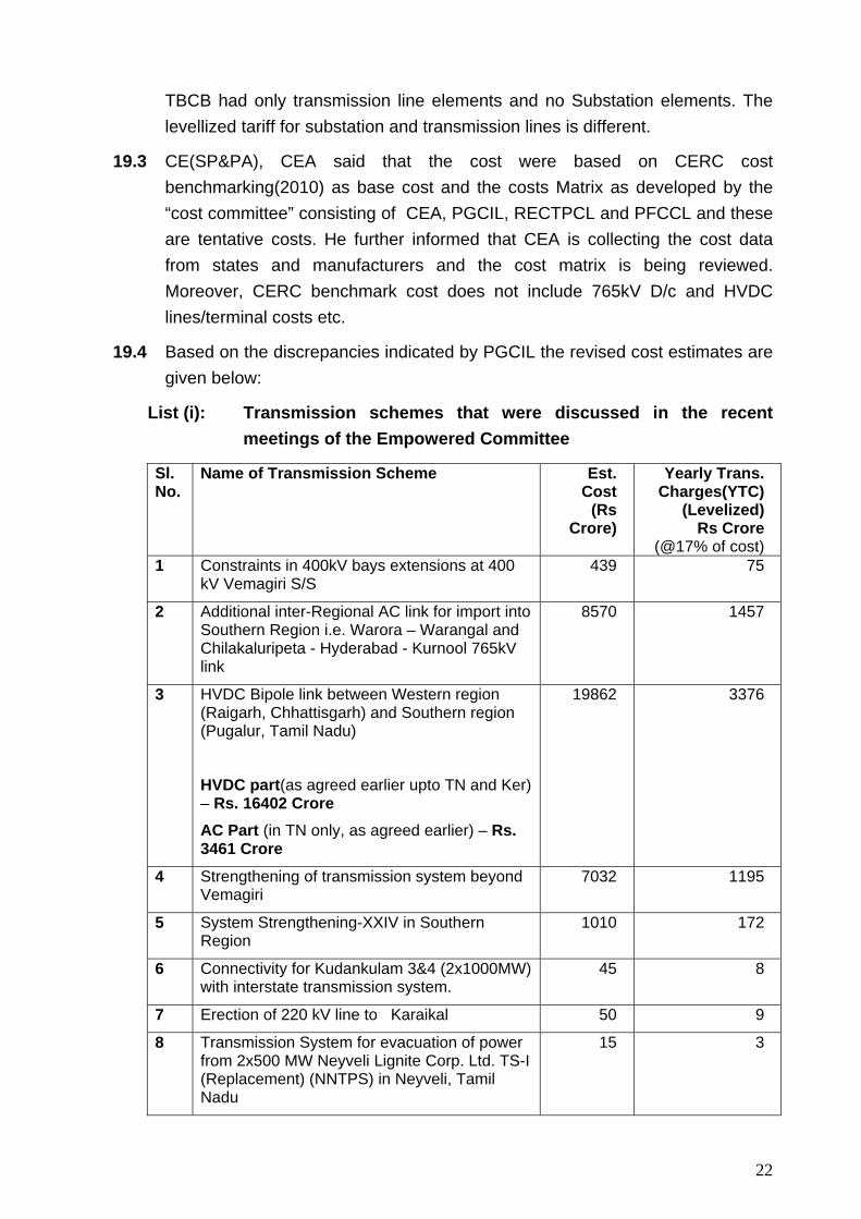
19.4 Based on the discrepancies indicated by PGCIL the revised cost estimates are given below:
List (i): Transmission schemes that were discussed in the recent meetings of the Empowered Committee
Sl. No.
Name of Transmission Scheme
Est. Cost
(Rs Crore)
Yearly Trans. Charges(YTC)
(Levelized) Rs Crore
(@17% of cost) 1 Constraints in 400kV bays extensions at 400
kV Vemagiri S/S 439 75
2 Additional inter-Regional AC link for import into Southern Region i.e. Warora – Warangal and Chilakaluripeta - Hyderabad - Kurnool 765kV link
8570 1457
3 HVDC Bipole link between Western region (Raigarh, Chhattisgarh) and Southern region (Pugalur, Tamil Nadu)
HVDC part(as agreed earlier upto TN and Ker) – Rs. 16402 Crore
AC Part (in TN only, as agreed earlier) – Rs. 3461 Crore
19862 3376
4 Strengthening of transmission system beyond Vemagiri
7032 1195
5 System Strengthening-XXIV in Southern Region
1010 172
6 Connectivity for Kudankulam 3&4 (2x1000MW) with interstate transmission system.
45 8
7 Erection of 220 kV line to Karaikal 50 9
8 Transmission System for evacuation of power from 2x500 MW Neyveli Lignite Corp. Ltd. TS-I (Replacement) (NNTPS) in Neyveli, Tamil Nadu
15 3
23
Sl. No.
Name of Transmission Scheme
Est. Cost
(Rs Crore)
Yearly Trans. Charges(YTC)
(Levelized) Rs Crore
(@17% of cost) 9 Connectivity lines for Maheshwaram
(Hyderabad) 765 / 400kV Pooling S/S 396 67
Total (A) 37419 6362
List (ii): Transmission schemes that are under construction by PGCIL
Sl.
No.
Name of Project Cost, in Rs Crore
Yearly Trans. Charges(YTC)
(Levelized) Rs Crore
(@17% of cost) 1 Transmission System associated with
KRAISHNAPATNAM UMPP-Part-B. 1927.16
2 Common System associated with East Coast Energy Pvt. Ltd. and NCC Power Proj. Ltd. LTOA Gen. Proj. in Srikakulam – Part-A.
1909.24
3 System Strengthening – XVII in Southern Regional Grid
1508.74
4 Common System associated with East Coast Energy Pvt. Ltd. and NCC Power Proj. Ltd. LTOA Gen. Proj. in Srikakulam – Part-C.
514
5 Common System Associated with ISGS Projects in Krishnapatnam area of Andhra Pradesh
1637.34
6 Common System Asociated with Costal Energen Pvt. Ltd and Ind-Barath Power Ltd. (LTOA) Gen. Proj. in Tuticorin area Part-B.
1940.13
7 System Strengthening – XIII SR Grid 487.49 8 System Strengthening in SR – XIV 297.33 9 Common System associated with East coast
energy and Private Ltd. and Ind-Barath Powe (Madras) Ltd. (LTOA) Gen. Poj. in Tuticorin area Part-A.
90.44
10 Transmission System Associated with Krishnapatnam UMPP – Par – C1
324.33
11 Common transmission Scheme associated with ISGS Project in Vemagiri Area of Andhra Pradesh – Part – A1
206.44
12 System Strengthening in SR – XVIII 1263.26 13 System Strengthening in SR – XIX 1935.35 14 common transmission scheme associated with
ISGS Projects in Nagapattinum/Cuddalore area of Tamil Nadu
182.8
15 Transmission System Associated with Contingency plan for Evacuation of Power from II&FS (2x600MW)
97.95
16 System Strengthening in SR – XXII 243.53 17 Sub station Extn. Works associated with Trans. 167.4
24
Sl.
No.
Name of Project Cost, in Rs Crore
Yearly Trans. Charges(YTC)
(Levelized) Rs Crore
(@17% of cost) System Required for evacuation of Power from Kudgi TPS (3x800 MW-PhI) of NTPC
18 Trans. System for connectivity for NCC Power Project Ltd.
188.75
19 System Strengthening in SR – XX 288.49 20 Common Transmission Scheme Associated
with ISGS Projects in Nagapattinum/Cuddalore area of Tamil Nadu – Part – A(b)
74.29
21 Sub station works associated with System Strengthening in SR for Import of Power from ER
972.42
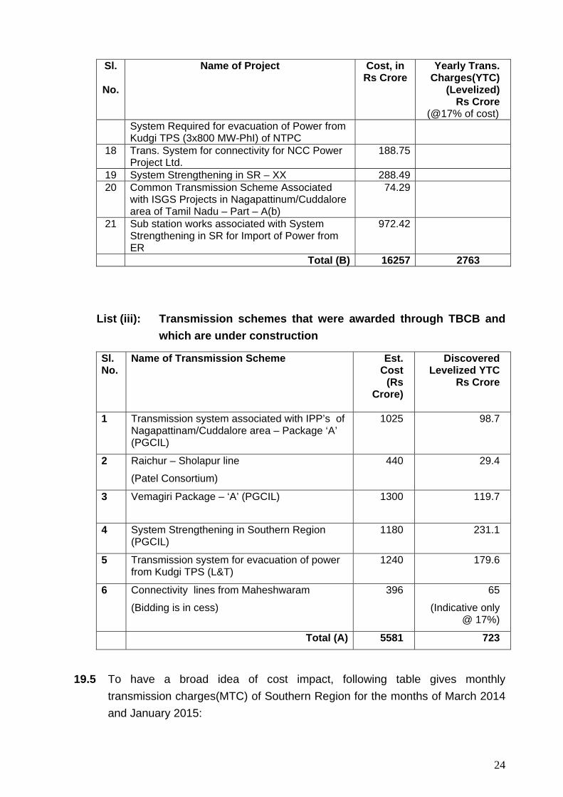
Total (B) 16257 2763
List (iii): Transmission schemes that were awarded through TBCB and which are under construction
Sl. No.
Name of Transmission Scheme
Est. Cost
(Rs Crore)
Discovered Levelized YTC
Rs Crore
1 Transmission system associated with IPP’s of Nagapattinam/Cuddalore area – Package ‘A’ (PGCIL)
1025 98.7
2 Raichur – Sholapur line
(Patel Consortium)
440 29.4
3 Vemagiri Package – ‘A’ (PGCIL) 1300 119.7
4 System Strengthening in Southern Region (PGCIL)
1180 231.1
5 Transmission system for evacuation of power from Kudgi TPS (L&T)
1240 179.6
6 Connectivity lines from Maheshwaram
(Bidding is in cess)
396 65
(Indicative only @ 17%)
Total (A) 5581 723
19.5 To have a broad idea of cost impact, following table gives monthly transmission charges(MTC) of Southern Region for the months of March 2014 and January 2015:
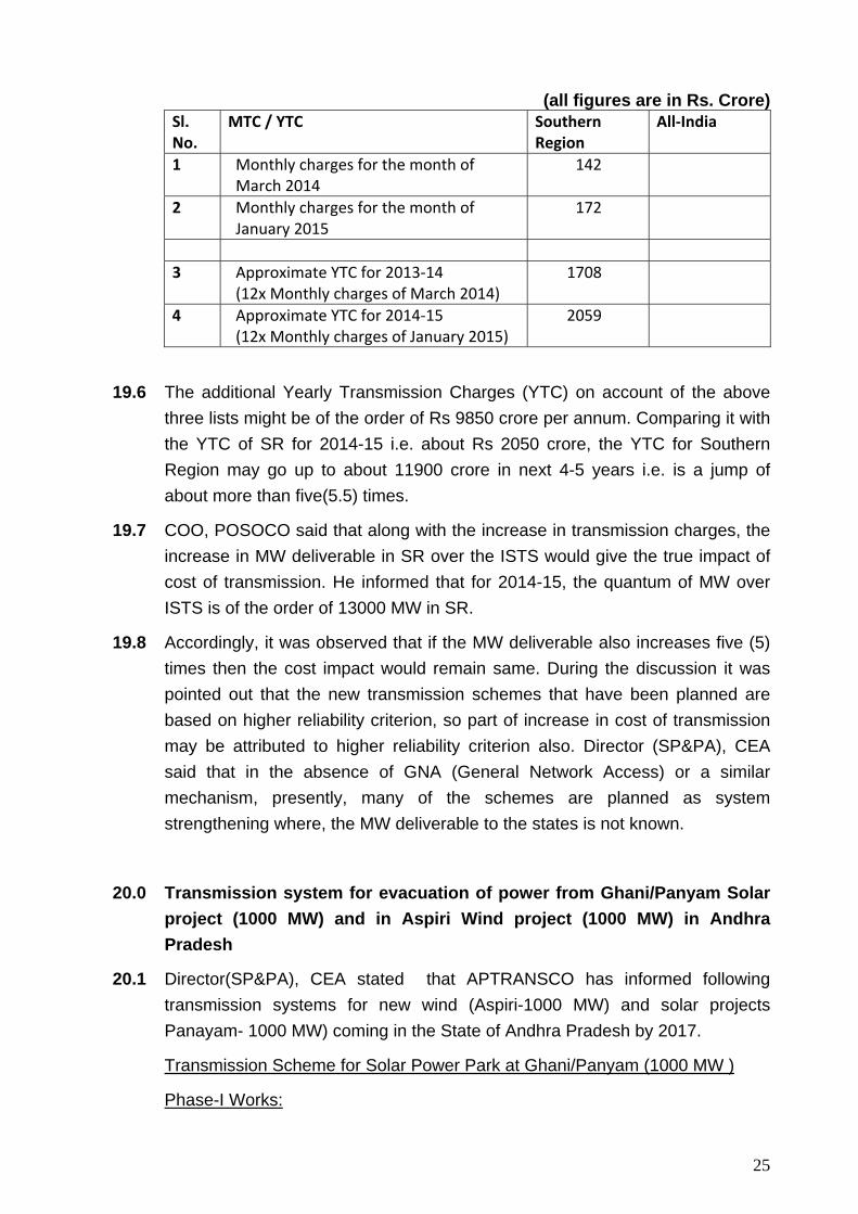
25
(all figures are in Rs. Crore) Sl. No.
MTC / YTC
Southern Region
All‐India
1 Monthly charges for the month of March 2014
142
2 Monthly charges for the month of January 2015
172
3 Approximate YTC for 2013‐14
(12x Monthly charges of March 2014) 1708
4 Approximate YTC for 2014‐15 (12x Monthly charges of January 2015)
2059
19.6 The additional Yearly Transmission Charges (YTC) on account of the above three lists might be of the order of Rs 9850 crore per annum. Comparing it with the YTC of SR for 2014-15 i.e. about Rs 2050 crore, the YTC for Southern Region may go up to about 11900 crore in next 4-5 years i.e. is a jump of about more than five(5.5) times.
19.7 COO, POSOCO said that along with the increase in transmission charges, the increase in MW deliverable in SR over the ISTS would give the true impact of cost of transmission. He informed that for 2014-15, the quantum of MW over ISTS is of the order of 13000 MW in SR.
19.8 Accordingly, it was observed that if the MW deliverable also increases five (5) times then the cost impact would remain same. During the discussion it was pointed out that the new transmission schemes that have been planned are based on higher reliability criterion, so part of increase in cost of transmission may be attributed to higher reliability criterion also. Director (SP&PA), CEA said that in the absence of GNA (General Network Access) or a similar mechanism, presently, many of the schemes are planned as system strengthening where, the MW deliverable to the states is not known.
20.0 Transmission system for evacuation of power from Ghani/Panyam Solar project (1000 MW) and in Aspiri Wind project (1000 MW) in Andhra Pradesh
20.1 Director(SP&PA), CEA stated that APTRANSCO has informed following transmission systems for new wind (Aspiri-1000 MW) and solar projects Panayam- 1000 MW) coming in the State of Andhra Pradesh by 2017.
Transmission Scheme for Solar Power Park at Ghani/Panyam (1000 MW )
Phase-I Works:
26
1) 400/220kV Substation at Gani/Panyam – 3x500 MVA. 2) 400kV QMDC Line from Kurnool to proposed 400kV Gani/Panyam SS–35
km. 3) 400kV Bay Extensions at Kurnool SS – 2 Nos.
Phase-II works :
4) 400kV QMDC Line from Jammalamadugu/ Kondapuram to the proposed 400kV Gani/Panyam SS – 90 kM.
Transmission Evacuation Scheme for 1000MW Wind Power at Aspiri:
1) 400/220kV Substation with 3x315 MVA 2) 400kV QMDC line from Aspiri to 400kV Uravakonda SS.
20.2 Director, APTRANSCO informed that the both the phases at Panyam would be of 500 MW each and are scheduled to be commissioned by March 2017. He also proposed that a + 100 MVAr STATCOM at Panayam would be required which would help in the event of Fault /Low Voltage near the Panyam bus.
20.3 COO, POSOCO asked if APTRANSCO is also planning to connect these projects with nearby 220kV sub-stations for meeting load. APTRANSCO informed that they are planning such connectivity. He also said that the wind machines and the Solar inverters should have LVRT capability and must not depend on grid based equipments like STATCOM etc for this requirement.
20.4 Director(SP&PA),CEA said that if the both phases in Panyam are to be commissioned by March 2017 and only a few months of difference between each phase, the transmission system may be implemented as one scheme. He also enquired whether the Aspiri wind machines and Panyam solar inverters meet the LVRT requirements. He also asked about details of sub-pooling of wind and solar power in Aspiri and Panyam at 220kV and that how they are being connected with the proposed main 400kV Pooling Station(s).
20.5 Director, APTRANSCO said the Aspiri machines would be of Type-3 and thus would meet LVRT requirements. Regarding the inverters at Panyam, he said that tendering for the solar panels and invertor stations are yet to be done and the specifications would be similar to those which NTPC is doing for NPKunta project. He also informed that for Aspiri there are no 220kV S/Ss in the vicinity, however, for Panyam, they would plan to connect with a few of the nearby 220kV S/Ss. He also said that the Panyam phases can be combined for the purpose of transmission infrastructure. Regarding sub-pooling of wind and solar power in Aspiri and Panyam at 220kV, he said that the details are being
27
worked out.
20.6 MS, SRPC suggested to include 2x125 MVAr Bus reactors at Aspiri and Panyam. He also emphasized that these 220kV Pooling Stations at Aspiri and Panyam should have LVRT capability for secure and stable operation of the grid.
20.7 After discussions, following was decided:
(i) Following would be transmission system for evacuation of power from Solar Power Park at Ghani/Panyam (1000 MW ) – to be implemented by APTRANSCO
1) 400/220kV Substation at Gani/Panyam – 3x500 MVA. 2) 400kV QMDC Line from Kurnool to proposed 400kV Gani/Panyam
SS–35 km. 3) 400kV Bay Extensions at Kurnool SS – 2 Nos. 4) 400kV QMDC Line from Jammalamadugu/ Kondapuram to the
proposed 400kV Gani/Panyam SS – 90 km 5) 2x125 MVAr Bus reactors at Panyam
(ii) Following would be transmission system for evacuation of power from Wind projects at Aspiri (1000 MW) – to be implemented by APTRANSCO
1) 400/220kV Substation with 3x315 MVA at Aspiri 2) 400kV QMDC line from Aspiri to 400kV Uravakonda SS 5) 2x125 MVAr Bus reactors at Aspiri
(iii) APTRANSCO would inform CEA the details of 220kV sub-pooling stations within a month, both for the Aspiri and the Panyam projects. They would also inform the connections with nearby 220kV Substations.
(iv) APTRANSCO would submit the studies for the proposed + 100 MVAr STATCOM at Panyam. The studies would consider the alternative locations like Urvakonda and Hindupur S/S which are better connected with the regional grid. They may also consider having a higher rating (the same as planned for STATCOMs in Southern Region for PGCIL under ISTS) for studies.
(v) While planning and implementing the above transmission system APTRANSCO should comply with the regulations of APERC, specially the “Terms and conditions of Open Access Regulations, 2005” of APERC and its amendments from time to time. APTRANSCO would also ensure that they would follow the “Technical standards for connectivity to the grid
28
Regulation 2007” of Central Electricity Authority and its amendments from time to time while planning and implementing the above transmission systems.
21.0 Transmission system for evacuation of power from NP Kunta Solar project (1500 MW) in Andhra Pradesh
21.1 PGCIL informed that M/s AP Solar Power Corporation Pvt Ltd (APSPCL) has applied for Connectivity and LTA under the CERC regulation for the 1500 MW N.P.Kunta Solar park. Out of this, 90% is for transmitting to AP DISCOMS and rest 10% to Southern Region as target region.
21.2 They further said that M/s APSPCL has informed that NP Kunta Solar park in distt. Anantpur, AP (1500 MW) is being developed in three phases. First and second phases are being developed with 250 MW and 750 MW capacities and target commissioning schedules are December 2015 and September 2016, respectively. The third phase of balance 500 MW capacity is targeted for December 2016. M/s APSPCL has also indicated that NP Kunta Solar park shall be aggregating power from NP Kunta Site (1000 MW) and Galiveedu Site (500 MW), which are contiguous to each other and both shall be connected to the 220/400kV NP Kunta Pooling Station for further dispersal of power. It was also clarified that total six (6) nos. 250 MW blocks (sub-pools) are proposed to be interconnected to 220/400 kV NP Kunta Pooling station through a 220kV D/C zebra transmission line from each sub-pooling station.
21.3 PGCIL also informed that APSPCL who is developing this solar park has entrusted the development of generation projects in Phase I and Phase II of 1000 MW in NPKunta Solar Park to M/s NTPC.
21.4 M/s NTPC informed that they have issued tenders for 250 MW for which price bid have also been opened. For additional 500 MW block also they had issued tenders recently. NTPC also confirmed that they shall abide by the present regulation regarding Technical standards for connectivity to Grid regulation.
21.5 Regarding STATCOM, POWERGRID said that the identified 400kV STATCOM at NP Kunta pooling station shall not only provide Grid Support but also help in voltage ride through support to solar generation. In addition, as NP Kunta is proposed to be connected to 400kV Hindupur, a major wind complex interconnected with other Wind generation pockets in Andhra Pradesh, this STATCOM shall also extend voltage support to generation projects in the event of contingency scenarios. The issue of placement of STATCOM at 220kV or 400kV NP Kunta Pooling Station was also deliberated. POWERGRID
29
clarified that as STATCOM is primarily identified to provide Grid Support, its effectiveness at 400kV shall be more w.r.t its placement at 220kV. On CEA query, POWERGRID confirmed that other proposed STATCOMS in Southern region viz. at 400 kV Udumalpet, Trichy and Hyderabad have been taken into consideration in studies.
21.6 PGCIL proposed following transmission system for NP Kunta ultra mega solar power park (1500 MW) in three phases.
Phase-I (250 MW) a. Establishment of 3x500 MVA, 400/220KV Substation at NP Kunta
Pooling Station b. LILO of 400KV Kadapa(Cuddapah) - Kolar S/c line at NP Kunta Pooling
Station c. 2 nos. 220kV line bays at NP Kunta Pooling Station d. 1x125 MVAR Bus Reactor at NP Kunta Pooling Station e. ±100 MVAR STATCOM at 400kV NP Kunta Pooling Station
Estimated Cost – Rs 320 Cr
Phase-II (750 MW) a. LILO of Kadapa(Cuddapah) – Hindupur 400kV D/c (Quad) line at NP
Kunta Pooling Station b. 6 nos. 220kV line bays at NP Kunta Pooling Station
Estimated Cost – Rs 185 Cr
Phase-III(500 MW) a. Augmentation of transformation capacity at NP Kunta station with 4th,
1x500 MVA, 400/220kV transformer b. 4 nos. 220kV line bays at NP Kunta Pooling Station
Estimated Cost – Rs 40 Cr
21.7 Director(SP&PA),CEA said that if these phases in NPKunta are to be
commissioned by December 2016 and only a few months of difference between each of the phases, the transmission system may be implemented as one scheme. He also said that, the proposed STATCOM, if required, may be shifted to phase-II. PGCIL said that they would prefer to order the complete transmission system for all the three stages together but with different delivery schedules matching with each phase. The delivery of STATCOM also can be matched with phase-II.
21.8 During discussions it was observed that the present CEA connectivity standards have do not have provision for LVRT compliance for solar power generations. The amendments in CEA technical standards may take one to two years. As being projected, a number of solar power plants/parks may be
30
implemented within 2 years, therefore, it was suggested that the solar projects coming in this intervening period may have STATCOM at each of their pooling or sub-pooling stations. It was also observed that merit of a ±20 MVAr or similar rating of STATCOM at each of six 220kV sub-pooling stations in the NP Kunta solar park may be evaluated in place of a single ±100 MVAr STATCOM at 400kV level because it being close to the generation inverters.
21.9 CEO, POSOCO stated that each inverter should be treated as a separate generating unit and it is the LVRT characteristic of the inverter which will hold the machine/generator and not STATCOM at 400kV level, as suggested in the evacuation system of N P Kunta. CEA added that if the STATCOMs are being proposed for grid support, as stated by PGCIL, we need to plan next set of STATCOMs (or combination of MSC and STATCOM) in the all-India grid, considering the new enhanced plans of wind and solar additions. CEA also requested PGCIL to submit status of implementation of the STATCOMs that have already been planned and urged them to speed up implementation of STATCOMs planned in September 2013 at Hyderabad, Udumalpet and Trichy for Southern Region grid.
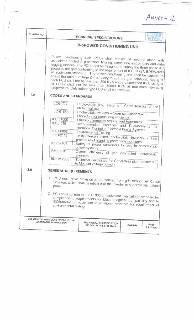
21.10 NTPC replied that they are following German Technical guidelines, for the development the NP Kunta generation project. They also furnished copies of the German technical guidelines and relevant extract of the specifications (Annex-II) that they have requested in the tendering for N P Kunta project. As such NTPC stated that the NPKunta inverters would have LVRT capabilities. After discussions, it was noted that there should be a mechanism to test LVRT capabilities, as stated by Solar generation developers or wind developers.
21.11 KSEBL sought clarification on the cost sharing of the new system being proposed as ISTS. The solar energy was exempted from payment of transmission charges and losses vide CERC regulation from 2011. Hon. CERC vide order dated 2.3.2015 in Petition No 3/SM/2015 stated that the Commission is in the process of finalizing the issue of exemption vide third amendment to the regulation and till then the present exemption could continue. The exemption from sharing of transmission charges and losses by solar generators is based on the CERC (Sharing of Inter State Transmission Charges and Losses) Regulations, 2010 which was notified on 15th June 2010 and came into effect from 01-07-2011. The status of solar energy industry has seen sea changes during this intervening period. KSEBL apprehended that the impact of the proposed schemes like that of NP Kunta UMSP with huge capacity of 1500 MW on the transmission charges of users of ISTS could be appreciable if the developer is continued to be exempted from paying the transmission charges. KSEB wanted to place on record the concerns in the
31
matter of exempting the transmission charges of solar evacuation especially when the installed capacity is at par with conventional generating stations. Further KSEBL supported the suggestion of CEO POSOCO to have the evacuation possibilities at 220kV level during the initial phase
21.12 Director (SP&PA), CEA asked whether the 220kV substations and transmission lines within N P Kunta Solar Park are being implemented by APTRANSCO or APSPCL. The LTA and connectivity application indicates that these works are being implemented by APTRANSCO.
21.13 APTRANSCO clarified that the internal transmission system at 220kV level is being carried out by them on deposit work basis from M/s APSPCL.
21.14 Director (SP&PA), CEA further enquired whether APSPCL is a transmission licensee in AP who is implementing these transmission works or whether they would be implementing these 220kV transmission systems as ‘dedicted transmission line’ in the capacity of a generator. He also enquired about eligibility of APSPCL to apply for connectivity and LTA with respect to the CERC regulations. He also enquired whether a PPA has been made with the AP DISCOMs for the 90% of the Capacity as given in the LTA application.
21.15 PGCIL clarified that till date they have not received PPA information from the applicant i.e. APSPCL. So, practically, the 90% part of the applied LTA is also a target State (to AP). APTRANSCO said that the PPA may be signed either by the APSPCL or by the generation developer e.g. NTPC in case of phase-I and II. Accordingly, it was observed that whether the LTA, in this case, should be applied by NTPC, or by APSPCL.
21.16 Regarding eligibility of APSPCL to seek ‘Connectivity’ or ‘LTA’, it was decided that CTU would approach CERC in this matter.
21.17 An issue of multiple injections at the 400kV S/S of PGCIL by the APSPCL was also raised, as in the ‘LTA’ application of CERC, more than one injection is allowed only for Drawl and not for Injection. In case of NPKunta, multiple injections are being proposed (six number of injections at the proposed 220/400kV S/S). On this issue also, it was decided that CTU would approach CERC.
21.18 COO, POSOCO asked if APTRANSCO is also planning to connect the 220kV sub-pooling stations with their nearby 220kV sub-stations for meeting load. He opined that as the solar power would not be available after evening, the 400kV S/s and the 220kV infrastructure in the park can meet loads in the local area. Also, if there is some disruption in the 400kV network, these 220kV interconnections can meet local loads. APTRANSCO informed that they are

32
planning such connectivity.
21.19 In regard to above, following extracts of the MNRE letter are worth considering:
As per Implementation scheme for Development of Solar Parks and Ultra Mega Solar Power Projects in the country commencing from 2014-15 and onwards (i.e. from the year 2014 – 15 to 2018 – 19) issued by the Government (MNRE) vide their letter No. 30/26/2014-15/NSM dated 12-Dec-2014, the following are mentioned:
“The Implementing Agency will also be entrusted with providing the following facilities to the solar project developers:
vii. Transmission facility consisting pooling station (with 400/220, 220/66 KV switchyard and respective transformers) to allow connection of individual projects with pooling station through a network of underground cables or overhead lines.”
“8. Transmission and evacuation of power from solar park
Interconnection of each plot with pooling stations through 66 KV /other suitable voltage underground or overhead cable will be the responsibility of the solar project developer.
The designated nodal agency will set up the pooling stations (with 400/220, 220/66 kV or as may be suitable switchyard and respective transformers) inside the solar park and will also draw transmission to transmit power to 220 kV/400 kV sub-station.
The responsibility of setting up a sub-station nearby the solar park to take power from one or more pooling stations will lie with the Central Transmission Utility (CTU) or the State Transmission Utility (STU), after following necessary technical and commercial procedures as stipulated in the various regulations notified by the Central/State Commission.
If the State Government is willing to buy over 50% of the power generated in the solar park, preference will be given to STU, which will ensure setting up of sub-station and development of necessary infrastructure for transmission of power from substation to load centres.
The designated implementing agency will intimate POWERGRID and CEA at least 6 months before so that the planning and execution can be carried out in time.
If the state is not willing to buy at least 50% of the power generated in the solar park, then CTU may be entrusted with the responsibility of setting up 400 KV or bigger sub-station right next to the solar park and its connectivity with the CTU.”
21.20 In this regard, as per letter no. 11/64/2014-PG dated 08-01-2015 of Ministry of Power regarding implementation of work related to transmission system for evacuation of power from 9 Solar Parks with a total capacity of 7020 MW being set up in seven states viz. Gujarat, Madhya Pradesh, Andhra Pradesh, Karnataka, UP, Meghalaya and Rajasthan, following has been stated:
33
“(i) The transmission line connecting solar parks to ISTS be declared as part of ISTS. (ii) PGCIL is assigned to take up construction of transmission lines including pooling stations from the solar generating parks on compressed time schedule basis.”
21.21 In view of above discussions it was agreed that though the proposed scheme is technically in order, however, it can be firmed up subject to resolving the regulatory issues. Regarding the proposed STATCOM at N P Kunta the same was agreed due to urgency in the matter as a special case, however, its delivery would be along with Phase-II of the project. Regarding the regulatory aspects, CTU would get clarification on - (i) eligibility for LTA, Connectivity, (ii)the issue of Multiple Injections, (iii) whether the proposed 400/220kV S/s which is in the premises of the solar park should be under scope of park developer or in STU/CTU, and (iv) whether LTA should be applied by actual generation developers who may sign PPA with AP DISCOMs or the APSPCL.
It was also decided that APTRANSCO would study planning of connecting its nearby 220kV S/S with the 220kV sub-pooling stations in NP Kunta Park.
CTU would carry out studies with CEA and respective STUs for finding optimum size and location of other STATCOMs in Southern Region that would provide grid support in view of upcoming wind and solar projects.
22.0 Modification for the System Strengthening-XXIV in Southern Region – GIS for Cuddapah 765kV S/s
22.1 Director(SP&PA), CEA stated that during 37th Standing Committee Meeting in SR held on 31/07/2014 System Strengthening-XXIV in Southern Region was agreed which covered: (i) Establishment of 765/400kV substation at Cuddapah with 2x1500 MVA transformers and 2x240 MVAr bus reactors.(ii) LILO of Kurnool-Thiruvalam 765 kV D/c at Cuddapah along with associated bays and (iii) Cuddapah-Hindupur 400 kV (Quad) D/C line along with associated bays and 80 MVAr switchable line reactor at Hindupur.
22.2 COO(CTU), PGCIL stated that the new 765/400KV substation at Cuddapah is proposed to be established in the land available adjacent to the existing substation. Keeping in view the requirement of 765kV and 400kV under present scope of work, it is not possible to accommodate these works as AIS in the available land. Acquisition of new land for Cuddapah Substation with the above scope of work would take considerable time. Keeping in view the
34
system requirement above works are to be implemented under compressed time schedule, therefore POWERGRID proposed that the new Cuddapah765/400kV S/s may be implemented as GIS type in the land available adjacent to the existing 400/220kV Cuddapah substation.
22.3 PGCIL informed that at Cuddapah the total land area is 106 Acres(existing 50 Acres and vacant 56acres). The additional land required for building AIS type would be 70acres and if it is built as GIS 50 acres more would be required. The difference in cost of establishing AIS and GIS would be Rs 50 crore only.
22.4 The matter was discussed and it was agreed that POWERGRID would implement the 765kV part as GIS and the augmentation of 400kV part as AIS for the Cuddapah765/400kV S/s.
23.0 ATS Tuticorin JV (2x500 MW) TPS of M/s NTPL
23.1 Director, CEA stated for power evacuation from the Tuticorin JV TPS, a 400 kV Tuticorin JV TPS – Chekkanurani (Madurai) D/C Quad line with 2 x 315 MVA, 400 kV/220 kV ICT at Tuticorin JV TPS had been agreed. Accordingly, M/s. PGCIL has erected 2 nos. of 400kV NTPL - Madurai DC Quad feeder lines. For evacuation of power from Coastal Energen, LILO of one circuit of the NTPL – Madurai D/C line was agreed as an interim arrangement.
23.2 Further, as per NTPL’s letter M/s. PGCIL is scheduled to commission 400kV system of its 400kV/765kV pooling station at Ettayapuram, near Tuticorin shortly with 4 nos. of 400 KV bays. The existing 400kV NTPL – Madurai and 400kV Coastal Energen – Madurai feeders will be shifted to pooling station. However, the 400kV tie between NTPL and M/s Coastal Energen would continue. So, with only 2 nos. of 400kV Ettayapuram PS – Madurai feeders being available, stability of power evacuation system of NTPL would be of concern.
23.3 PGCIL informed that as per the agreed scope of power evacuation system of Costal Energen is to construct a 400kV Quad D/C line from its switchyard to Tuticorin Pooling Station. As an interim arrangement, this line has been part completed by making LILO of one circuit of the NTPL – Madurai D/C line. After commissioning of the Costal Energen - Tuticorin P.S. 400kV Quad D/C line, the NTPL – Madurai/ Tuticorin Pooling Station D/C line would be restored.
23.4 Accordingly, the NTPL apprehension regarding the tie line between NTPL – Coastal Energen line, it was clarified that this tie line would be disconnected after commissioning of Costal Energen - Tuticorin P.S. 400kV Quad D/C line.
35
24.0 Change in SCCL Evacuation scheme:
24.1 Director(SP&PA),CEA said that M/s TSTRANSCO (Transmission Corporation of Telangana Limited) had proposed that SCCL – Nirmal 400 kV D/c line which was planned as evacuation system for 2x600 MW of SCCL, may be planned as Quad Moose line instead of Twin Moose line for evacuation of power from 3rd unit of 1x600 MW at the Singareni TPS at Jaipur location near Nirmal in Telangana.
24.2 The proposal was discussed and it was felt that to evacuate power from SCCL having total capacity of 1800 MW and meeting the reliability requirements as per the Transmission Planning Criteria, detailed system studies are needed.
24.3 To go ahead, the SCCL –Nirmal 400 kV Twin Moose D/C line may be planned as Quad D/C instead of Twin as envisaged earlier.
24.4 Additional transmissions system strengthening beyond Gajwel and Nirmal may be needed. Thus the transmission system for evacuation of power from the 3rd unit may be firmed up only after the detailed studies.
24.5 TSTRANSCO agreed to carry out the required studies and bring the matter in the next meeting of Standing Committee.
24.6 CEA urged that TSTRANSCO should comply with the regulations of Telangana State Electricity Regulator Commission and the regulations of APERC as applicable to them in accordance with TSERC (adoption Regulation 2014) i.e of Regulation no. 1 of 2014 while planning and implementing the above transmission system. Especially, they should comply with the “Terms and conditions of Open Access Regulations, 2005” of APERC and its amendments from time to time. TSTRANSCO would also ensure that they would follow the “Technical standards for connectivity to the grid Regulation 2007 of Central Electricity Authority and its amendments from time to time while planning and implementing the above transmission system.
25.0 Additional Agenda from PGCIL - following was decided:
25.1 Procurement of ERS substation: It was decided that PGCIL would discuss this issue with CEA and thereafter, the matter would be taken up in next meeting.
25.2 Converting Fixed Line Reactors into Switchable Line Reactors in Over Compensated lines: This item has already been covered earlier in the Minutes.
25.3 Replacement of 50 MVAr bus reactor with 125 MVAr at Mysore: This

36
matter would be re-discussed in the next meeting of this committee.
25.4 Procurement of 500 MVA ICT as spare instead of 315 MVA ICT approved under Ramagundum Transmission System, and Procurement of 3 NOS. 125 MVAr reactors instead of 3 NOS. 50 MVAr Reactors approved under Ramagundum Transmission System: This matter would be re-discussed in the next meeting of this committee.
26.0 Modifications in the scope of Raigarh – Pugalur – Kerala 6000 MW HVDC transmission system
In the meeting, it was noted that PGCIL has proposed modifications in the scope of the Raigarh – Pugalur - North Trichur 6000 MW HVDC system. The change in scope mainly is having a set of 2000 MW HVDC terminals at Pugalur and North Trichur in addition to the set of 6000 MW terminals at Raigarh and Pugalur. Also, the Pugalur – N.Trichur terminals have been proposed to be built using VSC based technology instead of the earlier conventional HVDC technology. The part of the Pugalur – N. Trichur is proposed to be built using DC cables. It was decided that PGCIL would provide detailed note on this modification along with documents on the new VSC technology.
37
Annex-I
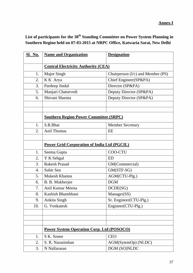
List of participants for the 38th Standing Committee on Power System Planning in Southern Region held on 07-03-2015 at NRPC Office, Katwaria Sarai, New Delhi Sl. No. Name and Organization Designation
Central Electricity Authority (CEA)
1. Major Singh Chairperson (I/c) and Member (PS) 2. K K Arya Chief Engineer(SP&PA) 3. Pardeep Jindal Director (SP&PA) 5. Manjari Chaturvedi Deputy Director (SP&PA) 6. Shivani Sharma Deputy Director (SP&PA)
Southern Region Power Committee (SRPC)
1. S.R.Bhat Member Secretary 2. Anil Thomas EE
Power Grid Corporation of India Ltd (PGCIL)
1. Seema Gupta COO-CTU 2. Y K Sehgal ED 3. Rakesh Prasad GM(Commercial) 4. Subir Sen GM(STF-SG) 5. Mukesh Khanna AGM(CTU-Plg.) 6. B. B. Mukherjee DGM 7. Anil Kumar Meena DCDE(SG) 8. Kashish Bhambhani Manager(SS) 9. Ankita Singh Sr. Engineer(CTU-Plg.)
10. G. Venkatesh Engineer(CTU-Plg.)
Power System Operation Corp. Ltd (POSOCO)
1. S K. Sonee CEO 2. S. R. Narasimhan AGM(SytemOp) (NLDC) 3. N Nallarasan DGM (SO)NLDC
38
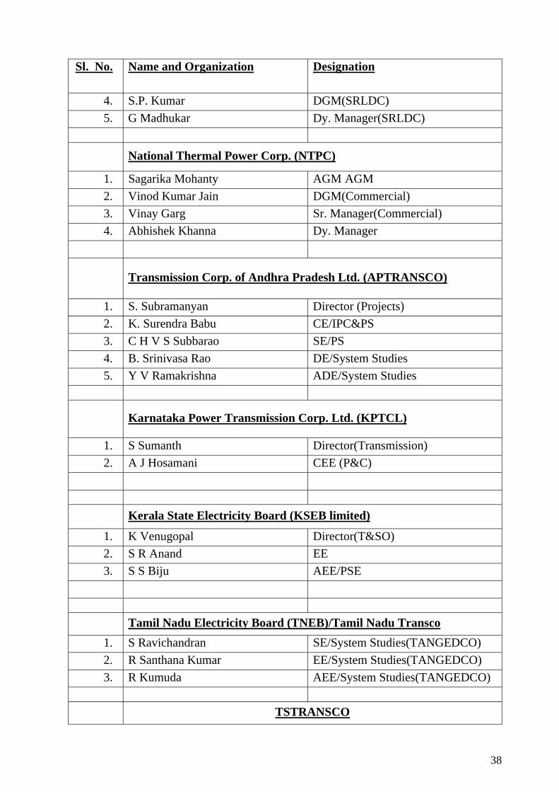
Sl. No. Name and Organization Designation
4. S.P. Kumar DGM(SRLDC) 5. G Madhukar Dy. Manager(SRLDC)
National Thermal Power Corp. (NTPC)
1. Sagarika Mohanty AGM AGM 2. Vinod Kumar Jain DGM(Commercial) 3. Vinay Garg Sr. Manager(Commercial) 4. Abhishek Khanna Dy. Manager
Transmission Corp. of Andhra Pradesh Ltd. (APTRANSCO)
1. S. Subramanyan Director (Projects) 2. K. Surendra Babu CE/IPC&PS 3. C H V S Subbarao SE/PS 4. B. Srinivasa Rao DE/System Studies 5. Y V Ramakrishna ADE/System Studies
Karnataka Power Transmission Corp. Ltd. (KPTCL)
1. S Sumanth Director(Transmission) 2. A J Hosamani CEE (P&C)
Kerala State Electricity Board (KSEB limited)
1. K Venugopal Director(T&SO) 2. S R Anand EE 3. S S Biju AEE/PSE
Tamil Nadu Electricity Board (TNEB)/Tamil Nadu Transco 1. S Ravichandran SE/System Studies(TANGEDCO) 2. R Santhana Kumar EE/System Studies(TANGEDCO) 3. R Kumuda AEE/System Studies(TANGEDCO)
TSTRANSCO
39
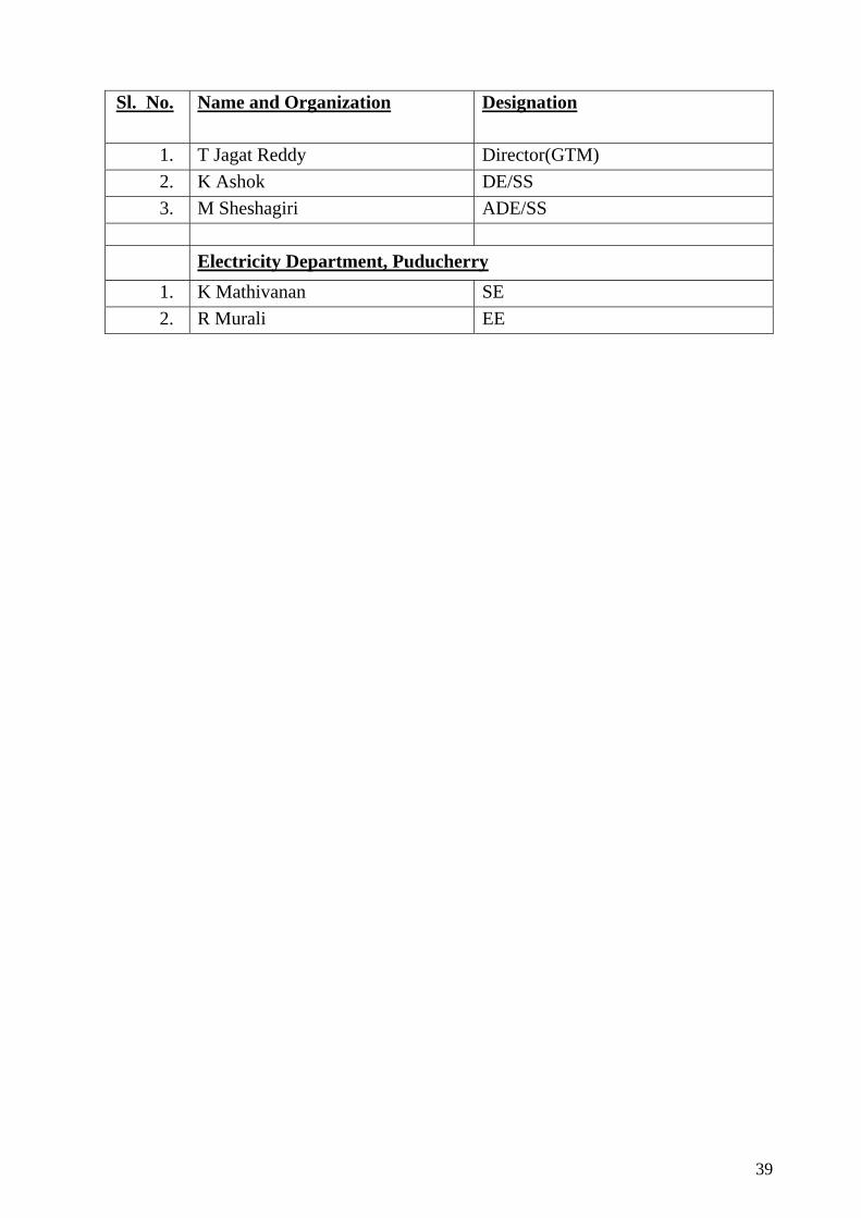
Sl. No. Name and Organization Designation
1. T Jagat Reddy Director(GTM) 2. K Ashok DE/SS 3. M Sheshagiri ADE/SS
Electricity Department, Puducherry
1. K Mathivanan SE 2. R Murali EE
The PCU shall remain connected to the grid as per Central Electricity AuthorityTechnical (standards for connectivity to the grid) regulation 2007 with all latestamendments and its components shall be designed accordingly.
Technical Guideline �Generating plants connected to the medium-voltage network�
© BDEW, June 2008 page 21/130
2.5.1.1 Steady-state voltage control
Steady-state voltage control means voltage control within the medium-voltage network un-
der normal operating conditions, where slow voltage changes in the distribution network are
kept within acceptable limits.
If required by the network operator and to meet network requirements, generating plants
must participate in steady-state voltage control within the medium-voltage network.
2.5.1.2 Dynamic network support
Dynamic network support means voltage control in the event of voltage drops within the
high and extra-high voltage network with a view to avoiding unintentional disconnections of
large feed-in power, and thus network collapse.
In the light of the strong increase in the number of generating plants to be connected to the
medium-voltage network, the integration of these plants into the dynamic network support
scheme is becoming ever more important. Consequently, these generating plants must gen-
erally participate in dynamic network support even if this is not required by the network op-
erator at the time of the plant�s connection to the network. That means that generating
plants must be able in technical terms
not to disconnect from the network in the event of network faults,
to support the network voltage during a network fault by feeding a reactive current
into the network,
not to extract from the medium-voltage network after fault clearance more inductive
reactive power than prior to the occurrence of the fault.
These requirements apply to all types of short circuits (i.e. to single-phase, two-phase and
three-phase short circuits).
Just like in the Transmission Code 20077, a distinction is made in these guidelines between
type-1 and type-2 generating plants with regard to their behaviour in the event of network
disturbances. A type-1 generating unit exists if a synchronous generator is directly (only
through the generator transformer) connected to the network. All other plants are type-2
generating units.
6 �Tonfrequenz-Rundsteuerung, Empfehlung zur Vermeidung unzulässiger Rückwirkun-gen�, 3rd edition 1997, published by VDEW 7 TransmissionCode 2007 �Network and System Rules of the German Transmission System Operators�, August 2007, published by VDN
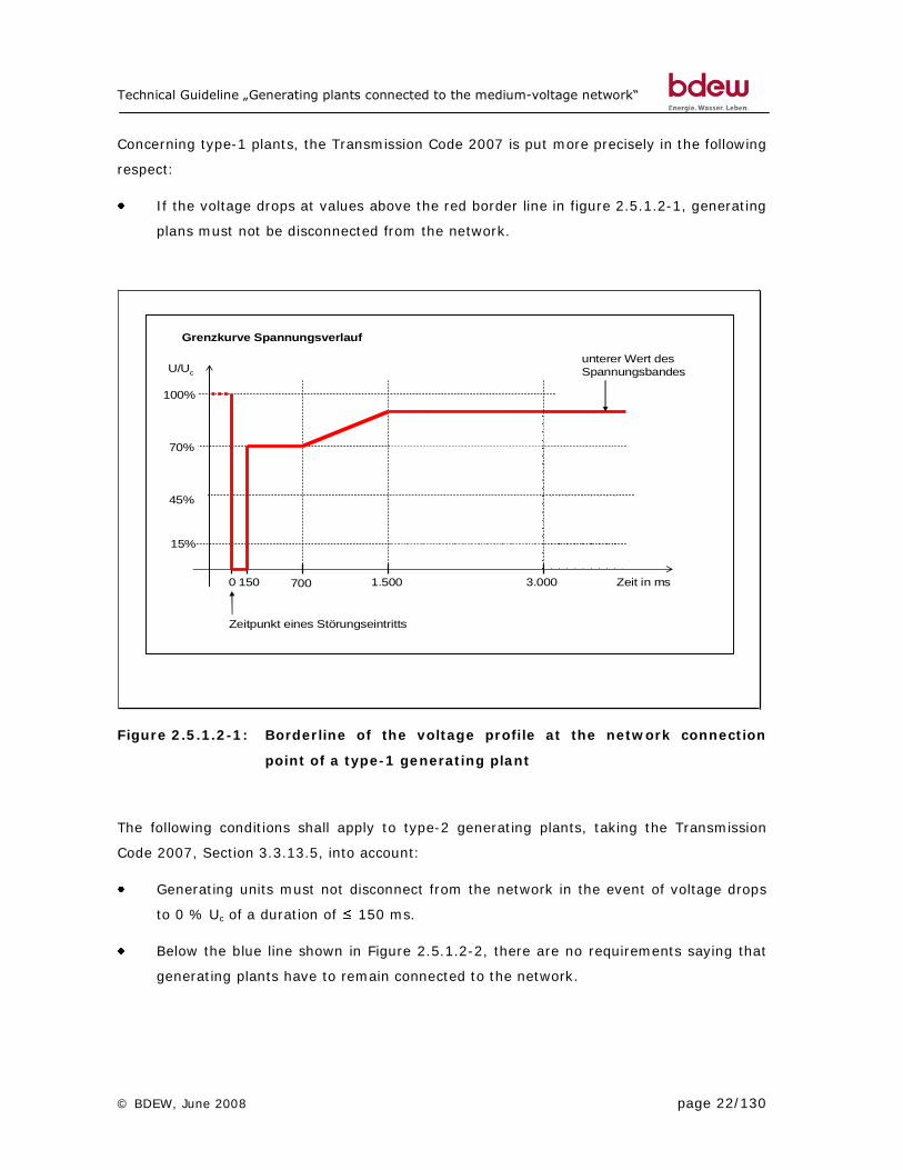
Technical Guideline �Generating plants connected to the medium-voltage network�
© BDEW, June 2008 page 22/130
Concerning type-1 plants, the Transmission Code 2007 is put more precisely in the following
respect:
If the voltage drops at values above the red border line in figure 2.5.1.2-1, generating
plans must not be disconnected from the network.
0 150 1.500
100%
70%
Zeit in ms
Zeitpunkt eines Störungseintritts
700
unterer Wert desSpannungsbandes
3.000
15%
45%
Grenzkurve Spannungsverlauf
U/Uc
Figure 2.5.1.2-1: Borderline of the voltage profile at the network connection
point of a type-1 generating plant
The following conditions shall apply to type-2 generating plants, taking the Transmission
Code 2007, Section 3.3.13.5, into account:
Generating units must not disconnect from the network in the event of voltage drops
to 0 % Uc of a duration of 150 ms.
Below the blue line shown in Figure 2.5.1.2-2, there are no requirements saying that
generating plants have to remain connected to the network.
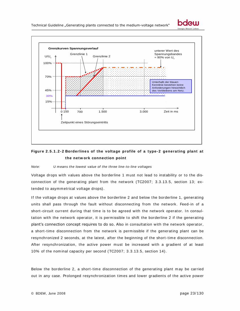
Technical Guideline �Generating plants connected to the medium-voltage network�
© BDEW, June 2008 page 23/130
0 150 1.500
100%
70%
Zeit in ms
Zeitpunkt eines Störungseintritts
700
unterer Wert desSpannungsbandes= 90% von Uc
3.000
15%
45%
Grenzlinie 1Grenzlinie 2
Unterhalb der blauen Kennlinie bestehen keine Anforderungen hinsichtlich des Verbleibens am Netz.
30%
Grenzkurven Spannungsverlauf
U/Uc
Figure 2.5.1.2-2 Borderlines of the voltage profile of a type-2 generating plant at
the network connection point
Note: U means the lowest value of the three line-to-line voltages
Voltage drops with values above the borderline 1 must not lead to instability or to the dis-
connection of the generating plant from the network (TC2007; 3.3.13.5, section 13; ex-
tended to asymmetrical voltage drops).
If the voltage drops at values above the borderline 2 and below the borderline 1, generating
units shall pass through the fault without disconnecting from the network. Feed-in of a
short-circuit current during that time is to be agreed with the network operator. In consul-
tation with the network operator, it is permissible to shift the borderline 2 if the generating
plant�s connection concept requires to do so. Also in consultation with the network operator,
a short-time disconnection from the network is permissible if the generating plant can be
resynchronized 2 seconds, at the latest, after the beginning of the short-time disconnection.
After resynchronization, the active power must be increased with a gradient of at least
10% of the nominal capacity per second (TC2007; 3.3.13.5, section 14).
Below the borderline 2, a short-time disconnection of the generating plant may be carried
out in any case. Prolonged resynchronization times and lower gradients of the active power
Technical Guideline �Generating plants connected to the medium-voltage network�
© BDEW, June 2008 page 24/130
increase after resynchronization as compared to those admissible above the borderline 2 are
permitted if they are agreed with the network operator (TC2007, 3.3.13.5, section 15).
The behaviour of type-2 generating plants in the case of automatic re-closure is described
more precisely in Annex B.3.
Depending on the concrete technical network conditions, the actual duration of the generat-
ing facility�s connection to the medium-voltage network can be reduced by requirements of
the network operator in terms of protection equipment.
For all generating plants, the rule shall apply that a current according to the Transmission
Code 2007 is to be supplied to the network for the duration of a symmetrical fault. Concern-
ing unsymmetrical faults, it is not permissible that during the duration of the fault reactive
currents be fed into the network which give rise to voltages higher than 1,1 Uc in non-faulty
phases at the network connection point.
As a matter of principle, the requirements in terms of dynamic network support apply to all
facilities irrespective of their type and connection variant. They shall be implemented
through setting of the generating plants� or units� control equipment.
The network operator shall determine the extent to which generating plants must partici-
pate in dynamic network support. A distinction is made between connections
directly via a separate circuit breaker bay to the bus-bar of a transforming station and
in the system operator�s medium-voltage network.
A general basic requirement is however that all generating plants remain connected to the
network in the case of voltage drops above the borderline in figure 2.5.1.2-1 or the border-
line in figure 2.5.1.2-1. Consequently, the network operator only determines whether or to
which extent a reactive current is to be supplied to the network by the generating facility in
the event of voltage drops.
Customer plants with generating plants turning into isolated operation in the event of dis-
turbances in the higher-voltage network to cover the customer�s own energy demand must
participate in network support until they are disconnected from the system operator�s me-
dium-voltage network. Isolated operation scheduled by the customer has to be agreed by
contract with the network operator.