Embed Size (px)
Citation preview

8/13/2019 Mitsubishi Aa084vc03 Lcdpanel Datasheet
http://slidepdf.com/reader/full/mitsubishi-aa084vc03-lcdpanel-datasheet 1/20
SIZE MITSUBISHI ELECTRIC SPECIFICATION REV.
A AA084VC03 A SHEET 1 OF 21
APPROVALS D ATE MITSUBISHI ELECTRIC
MELA ENG. ION CENUSE DEC. 3RD
, ‘99
MELA MKTG. D ALE M AUNU
MITSUBISHI/ADI
TFT-LCD MODULE
8.4-INCH VGA COLOR
AA084VC03
ECR # REV. HIST. DESCRIPTION APPROVED DATE
A First Release Ion Cenuse 12/12/99
TECHNICAL SPECIFICATION
AA084VC03
8.4-INCH TFT-LCD MODULE
FOR
INDUSTRIAL APPLICATIONS

8/13/2019 Mitsubishi Aa084vc03 Lcdpanel Datasheet
http://slidepdf.com/reader/full/mitsubishi-aa084vc03-lcdpanel-datasheet 2/20
SIZE MITSUBISHI ELECTRIC SPECIFICATION REV.
A AA084VC03 A SHEET 2 OF 21
TABLE OF CONTENTS
PARAGRAPH NUMBER
ITEM PAGE
COVER SHEET 1
TABLE OF CONTENTS 2
1 OVERVIEW 3
2 ABSOLUTE MAXIMUM RATINGS 4
3 ELECTRICAL CHARACTERISTICS 4, 5
4 INTERFACE PIN CONNECTION 6, 7
5 INTERFACE TIMING 8, 9, 10
6 BLOCK DIAGRAM 11
7 MECHANICAL SPECIFICATION 12, 13, 14
8 OPTICAL CHARACTERISTICS 15, 16
9 RELIABILITY TEST CONDITIONS 17
10 LIFE TIME OF THE BACKLIGHT LAMP 18
11 INSPECTION STANDARDS 19
12 HANDLING PRECAUTIONS FOR TFT-LCD MODULES 20, 21
8/13/2019 Mitsubishi Aa084vc03 Lcdpanel Datasheet
http://slidepdf.com/reader/full/mitsubishi-aa084vc03-lcdpanel-datasheet 3/20
SIZE MITSUBISHI ELECTRIC SPECIFICATION REV.
A AA084VC03 A SHEET 3 OF 21
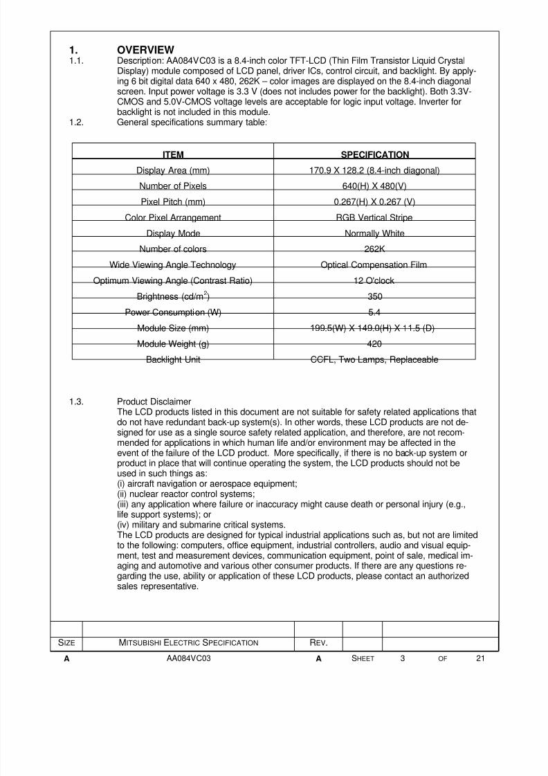
ITEM SPECIFICATION
Display Area (mm) 170.9 X 128.2 (8.4-inch diagonal)
Number of Pixels 640(H) X 480(V)
Pixel Pitch (mm) 0.267(H) X 0.267 (V)
Color Pixel Arrangement RGB Vertical Stripe
Display Mode Normally White
Number of colors 262K
Wide Viewing Angle Technology Optical Compensation Film
Optimum Viewing Angle (Contrast Ratio) 12 O'clock
Brightness (cd/m2) 350
Power Consumption (W) 5.4
Module Size (mm) 199.5(W) X 149.0(H) X 11.5 (D)
Module Weight (g) 420
Backlight Unit CCFL, Two Lamps, Replaceable
1. OVERVIEW1.1. Description: AA084VC03 is a 8.4-inch color TFT-LCD (Thin Film Transistor Liquid Crystal
Display) module composed of LCD panel, driver ICs, control circuit, and backlight. By apply-ing 6 bit digital data 640 x 480, 262K – color images are displayed on the 8.4-inch diagonalscreen. Input power voltage is 3.3 V (does not includes power for the backlight). Both 3.3V-CMOS and 5.0V-CMOS voltage levels are acceptable for logic input voltage. Inverter forbacklight is not included in this module.
1.2. General specifications summary table:
1.3. Product DisclaimerThe LCD products listed in this document are not suitable for safety related applications thatdo not have redundant back-up system(s). In other words, these LCD products are not de-signed for use as a single source safety related application, and therefore, are not recom-mended for applications in which human life and/or environment may be affected in theevent of the failure of the LCD product. More specifically, if there is no back-up system orproduct in place that will continue operating the system, the LCD products should not beused in such things as:(i) aircraft navigation or aerospace equipment;(ii) nuclear reactor control systems;(iii) any application where failure or inaccuracy might cause death or personal injury (e.g.,life support systems); or(iv) military and submarine critical systems.The LCD products are designed for typical industrial applications such as, but not are limited
to the following: computers, office equipment, industrial controllers, audio and visual equip-ment, test and measurement devices, communication equipment, point of sale, medical im-aging and automotive and various other consumer products. If there are any questions re-garding the use, ability or application of these LCD products, please contact an authorizedsales representative.

8/13/2019 Mitsubishi Aa084vc03 Lcdpanel Datasheet
http://slidepdf.com/reader/full/mitsubishi-aa084vc03-lcdpanel-datasheet 4/20
SIZE MITSUBISHI ELECTRIC SPECIFICATION REV.
A AA084VC03 A SHEET 4 OF 21
ITEM SYMBOL MIN MAX UNIT
Power Supply Voltage for LCD VCC –0.3 5.5 V
Logic Input Voltage VIN 0 7 V
Operating Temperature Top 0 50 °C
Storage Temperature Tstg –20 60 °C
ITEM SYMBOL MIN TYP MAX UNIT COMMENTSPower Supply Voltagefor LCD*
VCC 3.0 3.3 3.6 V (Note)
Power Supply Currentfor LCD*
ICC 240 400 mA (Note)
Permissive InputRipple Voltage
VRP 100 mVp-p VCC=+3.3V
Logic Input High VLH 2.4 5.5 V
Voltage Low VLL 0.0 0.8 V
Note * : See paragraph 3.4
ITEM SYMBOL MIN TYP MAX UNIT
Lamp Voltage VL 465 V
Lamp Current IL 5.0* mA
Lamp Starting Voltage VS 980 V
Note * : For typical luminance of 350cd/m2
2. ABSOLUTE MAXIMUM RATINGS2.1. Environmental conditions: humidity ≤85% RH, no condensation2.2. Summary Table:
3. ELECTRICAL CHARACTERISTICS3.1. Conditions: TFT-LCD module ambient temperature is 25°C3.2. Summary table:
3.3. Backlight3.3.1. The table below shows data for one lamp only.3.3.2. The TFT-LCD module has two identical lamps operated independently.3.3.3. Operation of both lamps is required in order to meet all the parameters in the AA084VC03
specification.

8/13/2019 Mitsubishi Aa084vc03 Lcdpanel Datasheet
http://slidepdf.com/reader/full/mitsubishi-aa084vc03-lcdpanel-datasheet 5/20
SIZE MITSUBISHI ELECTRIC SPECIFICATION REV.
A AA084VC03 A SHEET 5 OF 21
3.0V 3.0V
Data
0.3V
t1 t2 t3
VCC
VCC
3.0V
2.4Vtd
3.4. Notes3.4.1. VCC turn-on conditions :
t1 ≤ 10ms
0 < t2 ≤ 50ms
0 < t3 ≤ 50ms
3.4.2. VCC-dip conditions :
2.4V ≤ VCC < 3.0V and td ≤ 10msVCC < 2.4VVCC-dip conditions should also follow the VCC turn-on conditions.
3.4.3. Test condition for ICC Typical:64 gray-bar pattern480 line modeVCC = +3.3V
3.4.4. Test conditions for ICC (MAX) :1 X 1 checkerboard, black and white patternDC input voltage = 3.3V

8/13/2019 Mitsubishi Aa084vc03 Lcdpanel Datasheet
http://slidepdf.com/reader/full/mitsubishi-aa084vc03-lcdpanel-datasheet 6/20
SIZE MITSUBISHI ELECTRIC SPECIFICATION REV.
A AA084VC03 A SHEET 6 OF 21
PIN SYMBOL FUNCTION
1 GND Ground
2 CLK Dot clock
3 Hsync Horizontal sync.
4 Vsync Vertical sync.
5 GND Ground
6 R0 Red data (LSB)
7 R1 Red data
8 R2 Red data
9 R3 Red data
10 R4 Red data
11 R5 Red data (MSB)
12 GND Ground
13 G0 Green data (LSB)
14 G1 Green data
15 G2 Green data
16 G3 Green data
17 G4 Green data
18 G5 Green data (MSB)
19 GND Ground
20 B0 Blue data (LSB)
21 B1 Blue data
22 B2 Blue data
23 B3 Blue data
24 B4 Blue data
25 B5 Blue data (MSB)
26 GND Ground
27 DE Data enable
28 VCC Power supply
29 VCC Power supply
30 HREV Horizontal Image Shift-direction Select Signal
31 VREV Vertical Image Shift-direction Select Signal
*Note: The metal frame of the TFT-LCD module is connected to ground.
4. INTERFACE CONNECTORS PIN ASSIGNMENT4.1. Used connector: DF9C-31P-1V4.2. Input connector pin assignment table:
Top view of input connectorpin assignment

8/13/2019 Mitsubishi Aa084vc03 Lcdpanel Datasheet
http://slidepdf.com/reader/full/mitsubishi-aa084vc03-lcdpanel-datasheet 7/20
SIZE MITSUBISHI ELECTRIC SPECIFICATION REV.
A AA084VC03 A SHEET 7 OF 21
PIN NUMBER SYMBOL FUNCTION
1 CTH VBLH(High voltage)
3 CTL VBLL(Low voltage)
4.3. Backlight connector type (See paragraph 6)Backlight connector (CN2 and CN3): BHR-03VS-1 (JST)Backlight mating connector: SM02(8.0)B-BHS-TB (JST)
4.4. Backlight connector pin assignment table:

8/13/2019 Mitsubishi Aa084vc03 Lcdpanel Datasheet
http://slidepdf.com/reader/full/mitsubishi-aa084vc03-lcdpanel-datasheet 8/20
SIZE MITSUBISHI ELECTRIC SPECIFICATION REV.
A AA084VC03 A SHEET 8 OF 21
trCLK tfCLK
tCLK
Invalid Data 1 2 3 4 5 6 7 8 639 640 Invalid Data
Last Data
twCH
tDs tDh
twCL
First Data
tDEs
tDEh tDEh
tDEs
DCLK
DATA(R,G,B)
DENA
HD
DENA
VD
DENA
trDE tfDE
twDL
tfHS twHL
trHS tH=1/fH
tHFP
tHBP
tV=1/fV
tfVS twVL tVFP
trVS
tVBP
1 2 3 4 479 480LINE DATA
HD
VD
90%
10%
tr tftw
Definition of tr, twand tf
5. INTERFACE TIMING5.1. Timing Chart

8/13/2019 Mitsubishi Aa084vc03 Lcdpanel Datasheet
http://slidepdf.com/reader/full/mitsubishi-aa084vc03-lcdpanel-datasheet 9/20
SIZE MITSUBISHI ELECTRIC SPECIFICATION REV.
A AA084VC03 A SHEET 9 OF 21
ITEM SYMBOL MIN TYP MAX UNIT
Frequency fCLK 20 25 30 MHz
Period tCLK 33.3 40 50 ns
DCLK* Width-Low twCL 10 — — ns
Width-High twCH 10 — — ns
Rise Time trCLK — — 5 ns
Fall Time tfCLK — — 5 ns
DATA Set up Time tDs 5 — — ns
(R, G, B) Hold Time tDh 5 — — ns
Set up Time tDEs 5 — — ns
Hold Time tDEh 5 — — ns
Low Time twDL 90 — 168 tCLK
Rise Time trDE — — 5 nsDENA Fall Time tfDE — — 5 ns
Horizontal Front Porch tHFP 0 — — tCLK
Horizontal Back Porch tHBP 7 — — tCLK
Vertical Front Porch tVFP 1 20 — tH
Vertical Back Porch tVBP 8 20 — tH
Frequency fH 27 31.5 38 kHz
Period tH 730 — 808 tCLK
HD* Width Low twHL 5 — — tCLK
Rise Time trHS — — 10 ns
Fall Time tfHS — — 10 ns
Frequency fV 55 60 70 Hz
Period tV 489 — — tH
VD Width Low twVL 3 — — tH
Rise Time trVS — — 10 ns
Fall Time tfVS — — 10 ns
Note 1: DCLK and HD should be applied continuously at the input connector of the TFT-LCD mod-ule during operation, subject to VCC turn-on conditions.
Note 2: Accepted only 640 data and 480 lines.Note 3: Both HREV and VREV should be stable during operation.
5.2. Timing Specification
8/13/2019 Mitsubishi Aa084vc03 Lcdpanel Datasheet
http://slidepdf.com/reader/full/mitsubishi-aa084vc03-lcdpanel-datasheet 10/20
SIZE MITSUBISHI ELECTRIC SPECIFICATION REV.
A AA084VC03 A SHEET 10 OF 21
COLOR INPUT R D A T A G D A T A B D A T A
DATA R5
R4
R3
R2
R1
R0
G5
G4
G3
G2
G1
G0
B5
B4
B3
B2
B1
B0
MS
B
LS
B
MS
B
LS
B
MS
B
LS
B
BLACK 0 0 0 0 0 0 0 0 0 0 0 0 0 0 0 0 0 0
RED(63) 1 1 1 1 1 1 0 0 0 0 0 0 0 0 0 0 0 0
BASIC GREEN(63) 0 0 0 0 0 0 1 1 1 1 1 1 0 0 0 0 0 0
BLUE(63) 0 0 0 0 0 0 0 0 0 0 0 0 1 1 1 1 1 1
COLOR CYAN 0 0 0 0 0 0 1 1 1 1 1 1 1 1 1 1 1 1
MAGENTA 1 1 1 1 1 1 0 0 0 0 0 0 1 1 1 1 1 1
YELLOW 1 1 1 1 1 1 1 1 1 1 1 1 0 0 0 0 0 0
WHITE 1 1 1 1 1 1 1 1 1 1 1 1 1 1 1 1 1 1
RED(0) 0 0 0 0 0 0 0 0 0 0 0 0 0 0 0 0 0 0
RED(1) 0 0 0 0 0 1 0 0 0 0 0 0 0 0 0 0 0 0
RED(2) 0 0 0 0 1 0 0 0 0 0 0 0 0 0 0 0 0 0
RED ¦
¦
RED(62) 1 1 1 1 1 0 0 0 0 0 0 0 0 0 0 0 0 0
RED(63) 1 1 1 1 1 1 0 0 0 0 0 0 0 0 0 0 0 0
GREEN(0) 0 0 0 0 0 0 0 0 0 0 0 0 0 0 0 0 0 0
GREEN(1) 0 0 0 0 0 0 0 0 0 0 0 1 0 0 0 0 0 0
GREEN(2) 0 0 0 0 0 0 0 0 0 0 1 0 0 0 0 0 0 0
GREEN ¦
¦
GREEN(62) 0 0 0 0 0 0 1 1 1 1 1 0 0 0 0 0 0 0
GREEN(63) 0 0 0 0 0 0 1 1 1 1 1 1 0 0 0 0 0 0
BLUE(0) 0 0 0 0 0 0 0 0 0 0 0 0 0 0 0 0 0 0
BLUE(1) 0 0 0 0 0 0 0 0 0 0 0 0 0 0 0 0 0 1
BLUE(2) 0 0 0 0 0 0 0 0 0 0 0 0 0 0 0 0 1 0
BLUE ¦
¦
BLUE(62) 0 0 0 0 0 0 0 0 0 0 0 0 1 1 1 1 1 0
BLUE(63) 0 0 0 0 0 0 0 0 0 0 0 0 1 1 1 1 1 1
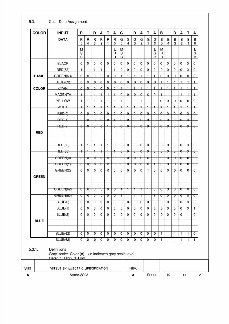
5.3. Color Data Assignment
5.3.1. Definitions
Gray scale: Color (n) → n indicates gray scale level.Data: 1=High, 0=Low

8/13/2019 Mitsubishi Aa084vc03 Lcdpanel Datasheet
http://slidepdf.com/reader/full/mitsubishi-aa084vc03-lcdpanel-datasheet 11/20
SIZE MITSUBISHI ELECTRIC SPECIFICATION REV.
A AA084VC03 A SHEET 11 OF 21
BACKLIGHT
CCFL
CCFL
CN2
CN3
1
3
1
3
6. BLOCK DIAGRAM
Power SupplyCircuit
Timing Con-verter
I n t e r f a c e C o n n e c t o r C N 1
Timing Signal
Display Data
Power
G1
G2
G480
S 1
S 2
S 1 9 1 9
S 1 9 2 0
Driver (source)
TFT-LCD
D r i v e r ( g a t e )

8/13/2019 Mitsubishi Aa084vc03 Lcdpanel Datasheet
http://slidepdf.com/reader/full/mitsubishi-aa084vc03-lcdpanel-datasheet 12/20
(
显 示 区 )
( 显 示 区 )

8/13/2019 Mitsubishi Aa084vc03 Lcdpanel Datasheet
http://slidepdf.com/reader/full/mitsubishi-aa084vc03-lcdpanel-datasheet 13/20

8/13/2019 Mitsubishi Aa084vc03 Lcdpanel Datasheet
http://slidepdf.com/reader/full/mitsubishi-aa084vc03-lcdpanel-datasheet 14/20
SIZE MITSUBISHI ELECTRIC SPECIFICATION REV.
A AA084VC03 A SHEET 14 OF 21
D(1, 1)
D(1, 480)
D(640, 1)
D(640, 480)
CN2
CN3
7.3. Scanning direction
This module has the capability of inverting scan direction by signaling from controller. Bothhorizontal and vertical scan direction can be selected independently. Note that scan direc-tion cannot be changed during operation.The following figure show how to scan the display image data on the LCD screen.The both image data sequences are the same.
D(1, 1)
D(1, 480)
D(640, 1)
D(640, 480)CN2
CN3
7.3.1 Normal scanHREV = H, VREV=H
7.3.2 Reverse scan
HREV = L, VREV=L

8/13/2019 Mitsubishi Aa084vc03 Lcdpanel Datasheet
http://slidepdf.com/reader/full/mitsubishi-aa084vc03-lcdpanel-datasheet 15/20
SIZE MITSUBISHI ELECTRIC SPECIFICATION REV.
A AA084VC03 A SHEET 15 OF 21
ITEM SYMBOL CONDITION MIN TYP MAX UNIT
Contrast Ratio CR
θ =φ
= 0° — 300 —
Luminance L θ = φ = 0° — 350 — cd/m2
Response tr θ = φ = 0° — 20 — ms
Time tf θ = φ = 0° — 30 — ms
Viewing Angle Horizontal φ CR ≥ 10 — –60~60 — °
Vertical θ — –40~50 — °
Red xy
— —
0.5630.336
— —
ColorGreen x
y θ = φ = 0° — —
0.3300.535
— — —
Coordinates Blue xy
— —
0.1590.150
— —
White xy
— —
0.3300.340
— —
H — 12 —Haze value of polarizer
LCD panel
Left (–) Right (+)
Upper (+)
Lower (–)
θ φ
8. OPTICAL CHARACTERISTICS8.1. Test conditions: Ta=25°C, VCC=3.3V, IL=5mA conditions. All measurements made using
BM-5A (TOPCON) or LCD-7000 (Otsuka Electronic) in a dark room, under no ambient lightconditions.
8.2. Summary table:
8.3. Definitions8.3.1. Contrast Ratio CR = ON (White) Luminance / OFF (Black) Luminance
8.3.2. Viewing Angle (θ , φ) - See drawing below :

8/13/2019 Mitsubishi Aa084vc03 Lcdpanel Datasheet
http://slidepdf.com/reader/full/mitsubishi-aa084vc03-lcdpanel-datasheet 16/20
SIZE MITSUBISHI ELECTRIC SPECIFICATION REV.
A AA084VC03 A SHEET 16 OF 21
8.3.3. Definition of Response Time tr and tf:
White
Blacktr
90% 90%
10% 10%
tf
Luminance

8/13/2019 Mitsubishi Aa084vc03 Lcdpanel Datasheet
http://slidepdf.com/reader/full/mitsubishi-aa084vc03-lcdpanel-datasheet 17/20
SIZE MITSUBISHI ELECTRIC SPECIFICATION REV.
A AA084VC03 A SHEET 17 OF 21
TEST ITEM CONDITIONS
High Temperature and High Humidity Operation 40 °C, 90%RH 500 hours
High Temperature and High Humidity Storage 60 °C, 90%RH 96 hours
Lowe Temperature Storage –20 °C, 96 hours
Thermal Shock (non-operating) Between –20°C(1 hour) and 60°C(1 hour) 5 cycles
TEST ITEM CONDITIONS
Shock (non-operating)
Shock level: 1470 m/s2 (150G)
Waveform: half sinusoidal wave, 2 msNumber of shocks: one shock input in each direction of three mutuallyperpendicular axis for a total of six shock inputs
Vibration (non-operating)
Vibration level: 9.8 m/s2 (1.0G)
Waveform: sinusoidalFrequency range: 5 to 500 HzFrequency sweep rate: 0.5 octave/minDuration: one sweep from 5 to 500 to 5Hz in each of three mutuallyperpendicular axis (total 3hr)
9. RELIABILITY TEST CONDITIONS9.1. Temperature and Humidity
9.2. Shock and Vibration
9.3. Judgment Standard – Pass/Fail criteria for reliability tests is defined as follow:
Pass: Normal display image with no obvious non-uniformity and no line defect.Fail : No display image, obvious non-uniformity, or line defect.

8/13/2019 Mitsubishi Aa084vc03 Lcdpanel Datasheet
http://slidepdf.com/reader/full/mitsubishi-aa084vc03-lcdpanel-datasheet 18/20
SIZE MITSUBISHI ELECTRIC SPECIFICATION REV.
A AA084VC03 A SHEET 18 OF 21
ITEM SYMBOL CONDITION UNIT
MIN TYP
Life Time TL IL=5.0mA,Ta=25°C 50,000 — hour
SPECIFICATION
10. LIFE TIME OF THE BACKLIGHT LAMP10.1. Definitions10.1.1. Lamp end of life is defined as the luminance of it become half of the initial value or lamp
does not turn on under 980V at 25°C.10.1.2. The life time of the backlight lamp depends on the ambient temperature. The life time may
be different from the time specified in the table below if the lamp is operated under extremetemperature conditions.
10.2. Summary Table

8/13/2019 Mitsubishi Aa084vc03 Lcdpanel Datasheet
http://slidepdf.com/reader/full/mitsubishi-aa084vc03-lcdpanel-datasheet 19/20
SIZE MITSUBISHI ELECTRIC SPECIFICATION REV.
A AA084VC03 A SHEET 20 OF 21
12. HANDLING PRECAUTIONS FOR TFT-LCD MODULE - Please observethe recommendations included in this paragraph when handling the
TFT-LCD modules! 12.1. ASSEMBLY PRECAUTIONS12.1.1. Please use the mounting hole on the module corners for installation and avoid bending or
wrenching LCD during assembly process. Do not drop, bend or twist the TFT-LCD moduleduring handling.
12.1.2. Guidelines for designing the TFT-LCD module enclosure:
12.1.2.1. Housing case must be designed carefully so as not to put stresses on LCD all sides and notto wrench module. Mechanical stress to the TFT-LCD module may degrade the reliabilityand overall performances of the display (like brightness uniformity degradation…etc.).
12.1.2.2. Keep sufficient clearance between LCD module back surface and housing when the LCDmodule is mounted. Approximately 1.0 mm of the clearance in the design is recommendedtaking into account the tolerance of LCD module thickness and mounting structure height onthe housing.
12.1.2.3. When some parts, such as, FPC cable and ferrite plate, are installed underneath the LCDmodule, still sufficient clearance is required, such as 0.5mm. This clearance is, especially,to be reconsidered when additional parts are inserted for EMI countermeasures.
12.1.2.4. Choose carefully the inverter location to avoid any stress to the lamp cable. The lamp cablealso should not interfere with the module installation into the enclosure.
12.1.2.5. Keep sufficient clearance between LCD module and the others components, such as in-
verter and speaker so as not to interfere with the LCD module. Approximately 1.0 mm ofthe clearance in the design is recommended.12.1.3. Do not apply pressure or scratch LCD panel surface with anything hard. Do not soil LCD
panel surface by touching with bare hands. (Polarizer film, surface of LCD panel is easy tobe flawed.)
12.1.4. Do not apply pressure on any parts on the rear side such as source TCP, gate TCP, controlcircuit board and FPCs during handling LCD module. If applying pressure to the TFT-LCDmodule is unavoidable, handle the LCD module with care not to damage them.
12.1.5. Wipe out LCD panel surface with absorbent cotton or soft cloth to clean the surface.12.1.6. Wipe out immediately any liquids which may have accidentally being sprayed on LCD panel
surface. Droplets on the LCD panel surface may alter the quality of the image.12.1.7. Do not disassemble the TFT-LCD module for any reasons. By doing so you void the war-
ranty of the TFT-LCD module and is very likely that the performances will be degraded con-siderably.
12.1.8. Do not touch metal frames with bare hands and soiled gloves. If fingerprints or dirt are notcleaned immediately with solvent it is very likely that permanent marks will be left on themetal surfaces.
12.1.9. Disconnect the lamp wires before handling the inverter otherwise is possible to damage thelamp and or the lamp wires by pulling it together with the inverter.
12.2. OPERATING PRECAUTIONS12.2.1. Turn off the power supply before connecting and disconnecting signal input cable.12.2.2. Do not change the setting of the adjustable resistors on TFT-LCD module subassemblies.
The adjustable resistors are properly set at the factory and any deviation from the factorysetting will compromise the performances of the TFT-LCD module.
12.2.3. When evaluating the optical characteristics of the display please note that will take longer
time for the backlight to stabilize if the ambient temperature is at the lower end of the tem-perature range.
12.2.4. Sudden changes of the ambient temperature may cause condensation on various surfacesof the TFT-LCD module and degrade the overall performances until the surfaces becomedry again.
12.2.5. Follow-up the general safety rules applying to generic electronic products.

8/13/2019 Mitsubishi Aa084vc03 Lcdpanel Datasheet
http://slidepdf.com/reader/full/mitsubishi-aa084vc03-lcdpanel-datasheet 20/20
SIZE MITSUBISHI ELECTRIC SPECIFICATION REV.
A AA084VC03 A SHEET 21 OF 21
12.3. PRECAUTIONS WITH ELECTRONICS12.3.1. This LCD module uses CMOS integrated circuits and other components subject to be af-
fected by electrostatic discharges. Use ESD protection equipment and follow all ESD safetyprocedures when handling the TFT-LCD modules.
12.3.2. Please remove protection film very slowly from the surface of LCD module to prevent fromhigh level electrostatic discharges. It is recommended to lift the protection film starting fromthe corner of the glass in proximity of the source and gate PWB ending at the corner of theglass furthest away from the electronics.
12.4. STORAGE PRECAUTIONS12.4.1. When you store LCDs for a long time, it is recommended to keep the temperature between
0°C ~ 40 °C without the exposure of sunlight and to keep the humidity less than 90%RH.12.4.2. Do not leave the LCDs in the environment of high humidity and high temperature such as
60°C 90%RH.
12.4.3. Do not expose the TFT-LCD modules to temperatures below –20°C.
12.5. SAFETY PRECAUTIONS12.5.1. When disposing LCDs it is recommended to break them into pieces. The broken pieces
should be washed with solvents such as acetone and ethanol. The residual solvent from thisprocess should be burned.
12.5.2. If any liquid leaks out of a damaged glass cell and comes in contact with the hands, wash itoff thoroughly with soap and water.
12.6. OTHERS12.6.1. Exposing the TFT-LCD module to strong incident light may negatively affect the display
characteristics because of polarizer film, color filter, and other materials degradation. Donot expose LCD module to direct sunlight or light with strong ultraviolet content.
12.6.2. Avoid any contact of the TFT-LCD module front surface with other objects or materials.12.6.3. Packaging and shipping12.6.3.1. Packaging box and inner case for LCD are designed to protect the LCDs from the damage
or scratching during transportation. Do not open the packaging box unnecessarily.12.6.3.2. Do not stack more than 5 boxes on top of each other because stack of 5 is maximum de-
signed limit. Do not turn over the boxes.12.6.3.3. Avoid excessive shock, the shipping boxes are not designed to be thrown. Excessive vibra-tions can also damage the boxes and the TFT-LCD modules inside.
12.6.3.4. Packaging box and the inner structures of it are made of cardboard. Avoid to have theboxes in contact with water or in high humidity environment which may cause the carton tobecome soft, or to break, damaging the TFT-LCD modules inside.