Embed Size (px)
Citation preview

MITSUBISHI Mitsubishi Industrial Robot
CRn-500 series INSTRUCTION MANUAL PROFIBUS Interface
BFP-A8348-D

BFP-A1155
■ CE マーキング対策部品取付要領 ■ EMC Component Installation Procedure PROFIBUS ケーブルへのフェライトコア取付要領 Procedure for Coupling a Ferrite Core with PROFIBUS Cable コントローラと PROFIBUS ユニット間の PROFIBUS ケーブルに、 添付のフェライトコアを下図のように取り付けてください。 また、フェライトコアを接続端子部から 30cm 以内に配置ください。 それ以外はノイズによる誤動作を起こす可能性があります。 The ferrite core should be connected to the PROFIBUS cable at a location between the controller and the other PROFIBUS unit, with the controller being within 30 cm of the Ferrite core (see figure below). If the ferrite core is not connected to PROFIBUS cable in this manner, emission noise could cause malfunction.
フェライトコアFerrite core
ナイロンバンド Nylon band
ロボットコントローラ側 Robot controller side
PROFIBUS ケーブルPROFIBUS cable
30cm 以内 Within 30cm
金属クランプ (推奨品: AL4 *RICHCO INC) Metal clamp (Recommended product: AL4 *RICHCO INC)
*1
*1 もしノイズによる影響を受けやすい環境下でご使用の場合は、PROFIBUS ケーブ
ルのカバーを剥き、金属クランプを利用して、シールドを直接筐体のアースに落と
してください。 If the device is operating in an environment where it can be easily affected by emission noise, strip off the covering of the PROFIBUS cable and, using the metal clamp, connect the shield directly to the unit’s ground.

BFP-A1156
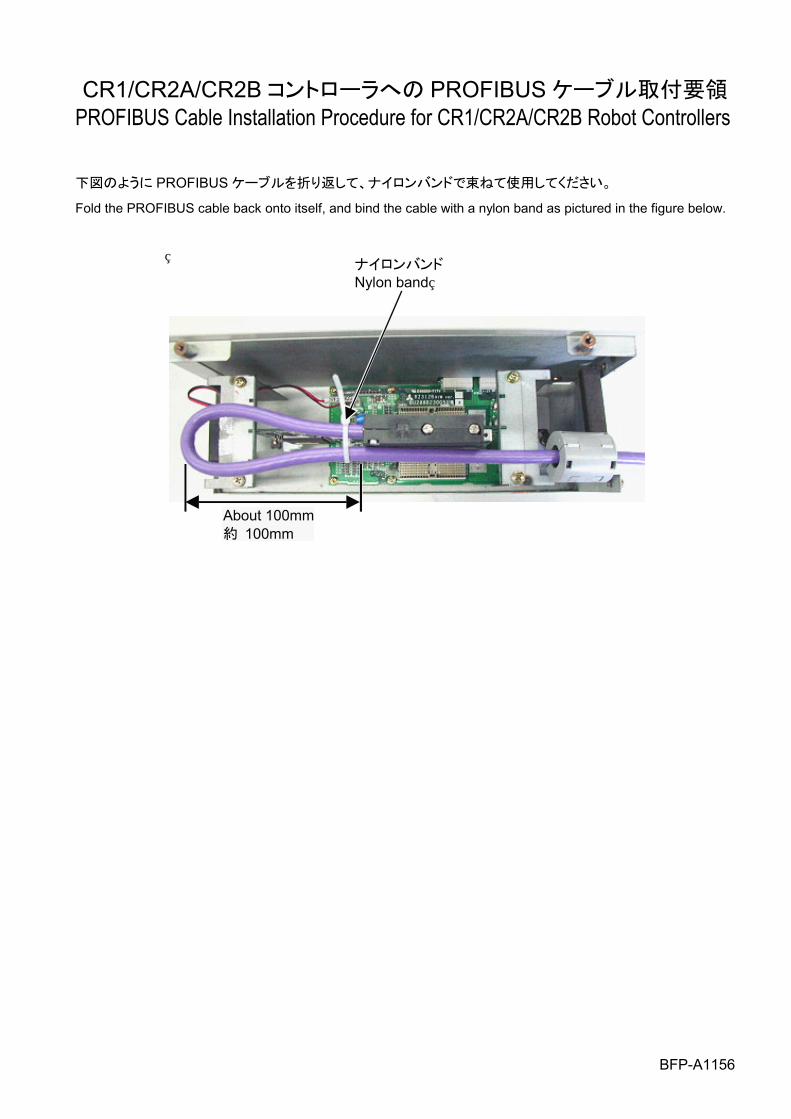
CR1/CR2A/CR2B コントローラへの PROFIBUS ケーブル取付要領 PROFIBUS Cable Installation Procedure for CR1/CR2A/CR2B Robot Controllers 下図のように PROFIBUS ケーブルを折り返して、ナイロンバンドで束ねて使用してください。
Fold the PROFIBUS cable back onto itself, and bind the cable with a nylon band as pictured in the figure below.
ナイロンバンドNylon band
About 100mm 約 100mm
BFP-A1156
CR1/CR2A/CR2B/CR3 コントローラへの CE マーキング対策による PROFIBUS ケーブル取付実施例
Examples of installing PROFIBUS cables with CE marking measure to CR1/CR2A/CR2B/CR3 robot controllers
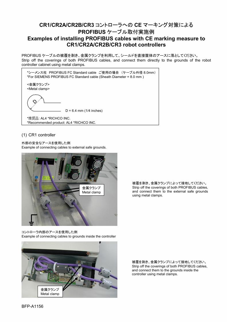
PROFIBUS ケーブルの被覆を剥き、金属クランプを利用して、シールドを直接筐体のアースに落としてください。 Strip off the coverings of both PROFIBUS cables, and connect them directly to the grounds of the robot controller cabinet using metal clamps.
*シーメンス社 PROFIBUS FC Standard cable ご使用の場合 (ケーブル外径 8.0mm) *For SIEMENS PROFIBUS FC Standard cable (Sheath Diameter = 8.0 mm ) <金属クランプ> <Metal clamp>
D
D = 6.4 mm (1/4 inches) *推奨品: AL4 *RICHCO INC. *Recommended product: AL4 *RICHCO INC.
(1) CR1 controller 外部の安全なアースを使用した例 Example of connecting cables to external safe grounds.
コントローラ内部のアースを使用した例 Example of connecting cables to grounds inside the controller
被覆を剥き、金属クランプによって接地してください。Strip off the coverings of both PROFIBUS cables, and connect them to the grounds inside the controller using metal clamps.
被覆を剥き、金属クランプによって接地してください。Strip off the coverings of both PROFIBUS cables, and connect them to the external safe grounds using metal clamps.
金属クランプMetal clamp
金属クランプ Metal clamp
BFP-A1156
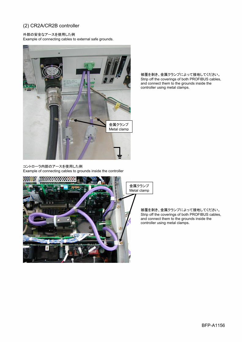
(2) CR2A/CR2B controller 外部の安全なアースを使用した例 Example of connecting cables to external safe grounds.
コントローラ内部のアースを使用した例 Example of connecting cables to grounds inside the controller
被覆を剥き、金属クランプによって接地してください。Strip off the coverings of both PROFIBUS cables, and connect them to the grounds inside the controller using metal clamps.
被覆を剥き、金属クランプによって接地してください。Strip off the coverings of both PROFIBUS cables, and connect them to the grounds inside the controller using metal clamps.
金属クランプMetal clamp
金属クランプMetal clamp
BFP-A1156
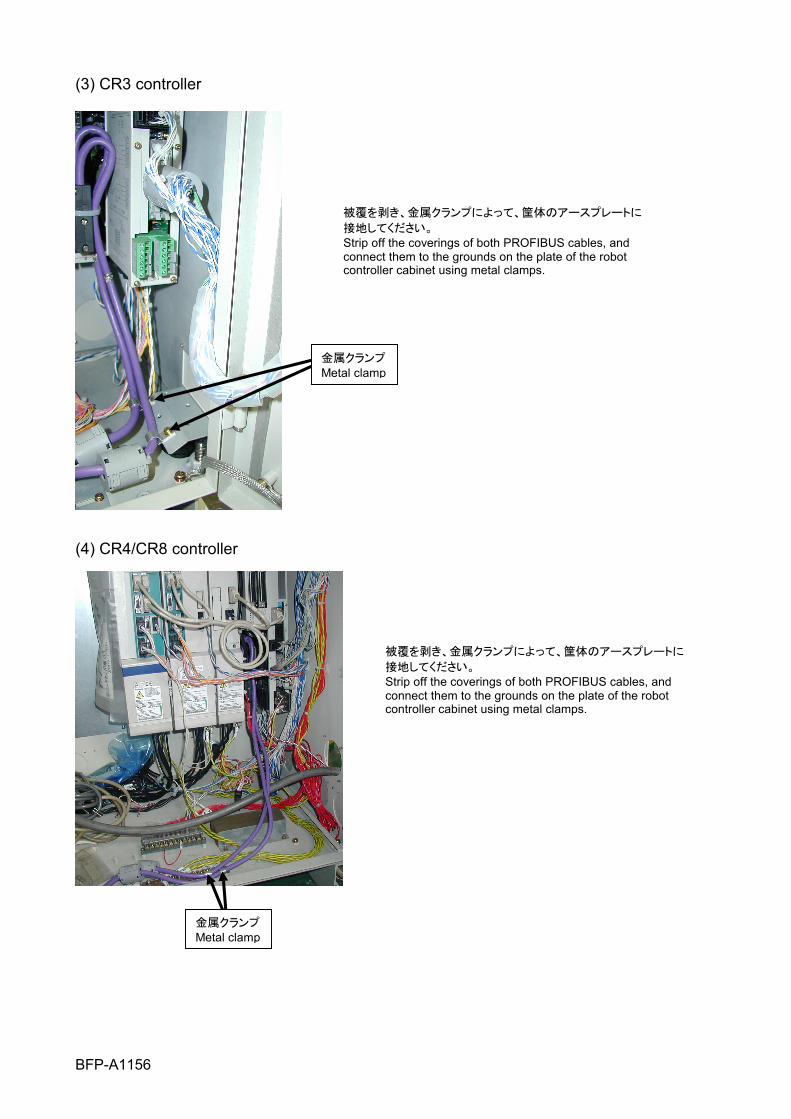
(3) CR3 controller
(4) CR4/CR8 controller
被覆を剥き、金属クランプによって、筐体のアースプレートに
接地してください。 Strip off the coverings of both PROFIBUS cables, and connect them to the grounds on the plate of the robot controller cabinet using metal clamps.
被覆を剥き、金属クランプによって、筐体のアースプレートに
接地してください。 Strip off the coverings of both PROFIBUS cables, and connect them to the grounds on the plate of the robot controller cabinet using metal clamps.
金属クランプMetal clamp
金属クランプ Metal clamp
■Revision History
Print date Instruction manual No. Revision content 2004-03-22 BFP-A8348Z First print. 2004-04-13 BFP-A8348-* Formal style. 2004-07-30 BFP-A8348-A Added the PBCNT parameter.
Error in writing correction. 2004-09-01 BFP-A8348-B Error in writing correction. 2004-01-31 BFP-A8348-C Error in writing correction.
2009-09-30 BFP-A8348-D The EC Declaration of Conformity was changed. (Correspond to the EMC directive; 2006/42/EC)

■Introduction Thank you very much for purchasing this product for Mitsubishi Electric Corporation's CR-500 series industrial robots. PROFIBUS interface is an add-on option that is used in combination with CR-500 series controllers to add PROFIBUS field network functionality to robot controllers. Please make sure to read this document thoroughly and understand its information before start using the PROFIBUS interface. This PROFIBUS interface card functions as a slave station of PROFIBUS-DP. This manual is described with the assumption that the reader has an understanding of the basic operations and functions of Mitsubishi Electric Industrial Robot CR-500 Series. For details of the basic operations, refer to the "Detailed explanations of functions and operations BFP-A5992."
• No part of this manual may be reproduced by any means or in any form, without prior consent from Mitsubishi. • The details of this manual are subject to change without notice • An effort has been made to make full descriptions in this manual. However, if any discrepancies or unclear
points are found, please contact your dealer. • The information contained in this document has been written to be accurate as much as possible.
Please interpret that items not described in this document "cannot be performed." or "alarm may occur". • This Instruction Manual is original
Copyright© 2004 MITSUBISHI ELECTRIC CORPORATION. ALL RIGHTS RESERVED.
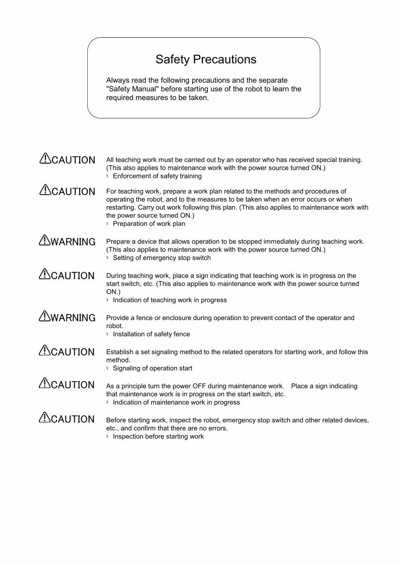
All teaching work must be carried out by an operator who has received special training. (This also applies to maintenance work with the power source turned ON.) →Enforcement of safety training For teaching work, prepare a work plan related to the methods and procedures of operating the robot, and to the measures to be taken when an error occurs or when restarting. Carry out work following this plan. (This also applies to maintenance work with the power source turned ON.) →Preparation of work plan Prepare a device that allows operation to be stopped immediately during teaching work. (This also applies to maintenance work with the power source turned ON.) →Setting of emergency stop switch
During teaching work, place a sign indicating that teaching work is in progress on the start switch, etc. (This also applies to maintenance work with the power source turned ON.) →Indication of teaching work in progress Provide a fence or enclosure during operation to prevent contact of the operator and robot. →Installation of safety fence
Establish a set signaling method to the related operators for starting work, and follow this method. →Signaling of operation start
As a principle turn the power OFF during maintenance work. Place a sign indicating that maintenance work is in progress on the start switch, etc. →Indication of maintenance work in progress
Before starting work, inspect the robot, emergency stop switch and other related devices, etc., and confirm that there are no errors. →Inspection before starting work
Always read the following precautions and the separate "Safety Manual" before starting use of the robot to learn the required measures to be taken.
Safety Precautions
WARNING
CAUTION
Always read the following precautions and the separate "Safety Manual" before starting use of the robot to learn the required measures to be taken.
Safety Precautions
CAUTION
CAUTION
CAUTION
WARNING
CAUTION
CAUTION
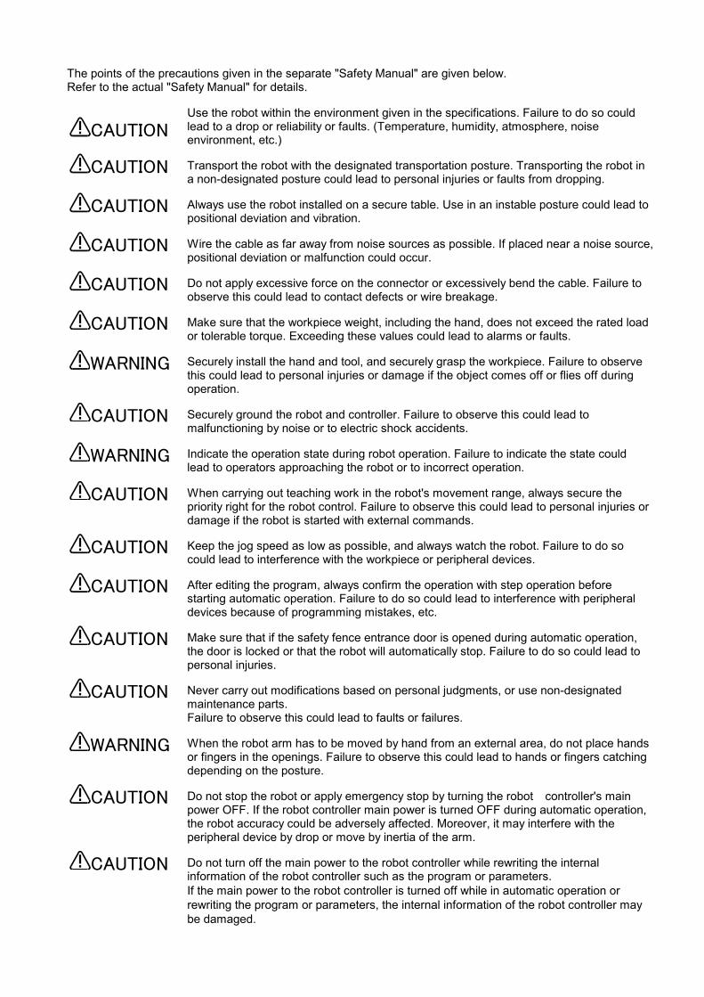
The points of the precautions given in the separate "Safety Manual" are given below. Refer to the actual "Safety Manual" for details.
Use the robot within the environment given in the specifications. Failure to do so could lead to a drop or reliability or faults. (Temperature, humidity, atmosphere, noise environment, etc.) Transport the robot with the designated transportation posture. Transporting the robot in a non-designated posture could lead to personal injuries or faults from dropping. Always use the robot installed on a secure table. Use in an instable posture could lead to positional deviation and vibration. Wire the cable as far away from noise sources as possible. If placed near a noise source, positional deviation or malfunction could occur. Do not apply excessive force on the connector or excessively bend the cable. Failure to observe this could lead to contact defects or wire breakage. Make sure that the workpiece weight, including the hand, does not exceed the rated load or tolerable torque. Exceeding these values could lead to alarms or faults. Securely install the hand and tool, and securely grasp the workpiece. Failure to observe this could lead to personal injuries or damage if the object comes off or flies off during operation. Securely ground the robot and controller. Failure to observe this could lead to malfunctioning by noise or to electric shock accidents. Indicate the operation state during robot operation. Failure to indicate the state could lead to operators approaching the robot or to incorrect operation. When carrying out teaching work in the robot's movement range, always secure the priority right for the robot control. Failure to observe this could lead to personal injuries or damage if the robot is started with external commands. Keep the jog speed as low as possible, and always watch the robot. Failure to do so could lead to interference with the workpiece or peripheral devices. After editing the program, always confirm the operation with step operation before starting automatic operation. Failure to do so could lead to interference with peripheral devices because of programming mistakes, etc. Make sure that if the safety fence entrance door is opened during automatic operation, the door is locked or that the robot will automatically stop. Failure to do so could lead to personal injuries. Never carry out modifications based on personal judgments, or use non-designated maintenance parts. Failure to observe this could lead to faults or failures. When the robot arm has to be moved by hand from an external area, do not place hands or fingers in the openings. Failure to observe this could lead to hands or fingers catching depending on the posture. Do not stop the robot or apply emergency stop by turning the robot controller's main power OFF. If the robot controller main power is turned OFF during automatic operation, the robot accuracy could be adversely affected. Moreover, it may interfere with the peripheral device by drop or move by inertia of the arm. Do not turn off the main power to the robot controller while rewriting the internal information of the robot controller such as the program or parameters. If the main power to the robot controller is turned off while in automatic operation or rewriting the program or parameters, the internal information of the robot controller may be damaged.
CAUTION
CAUTION
WARNING
CAUTION
CAUTION
CAUTION
CAUTION
CAUTION
CAUTION
CAUTION
CAUTION
CAUTION
CAUTION
CAUTION
CAUTION
WARNING
WARNING
i
Contents
1 Before Using the PRIFUBUS Interface ....................................................................................................1-1 1.2 How to Use the Instruction Manual ..................................................................................................1-1
2 Flow of Operations ...................................................................................................................................2-1 2.1 Flowchart..........................................................................................................................................2-1
3 Functions and Specification of the PROFIBUS Interface .........................................................................3-1 3.1 What Is PROFIBUS?........................................................................................................................3-1 3.2 Specification of the PROFIBUS Interface Card ..............................................................................3-2
3.2.1 General Layout of the Card ..........................................................................................................3-2 3.2.2 LED Explanation...........................................................................................................................3-2 3.2.3 Hardware Specification.................................................................................................................3-3 3.2.4 Software Specification ..................................................................................................................3-4
3.2.1.1 Robot Parameter Specification..............................................................................................3-4 3.2.1.2 Specification Relating to Robot Language ............................................................................3-5 3.2.1.3 Specification Relating to PROFIBUS Signal Numbers..........................................................3-5
3.2.1.3.1 CR-500 Series Entire Signal Assignment........................................................................3-5 3.2.1.3.2 PROFIBUS Robot Input Signal Assignment....................................................................3-6 3.2.1.3.3 PROFIBUS Robot Output Signal Assignment .................................................................3-7 3.2.1.3.4 Bit Arrangement of One Word .........................................................................................3-8 3.2.1.3.5 Example of PROFIBUS Signal Assignment ....................................................................3-8
4 Items to Be Checked Before Using This Product (Procedure 1)..............................................................4-1 4.1 Checking the Product .......................................................................................................................4-1 4.2 Devices to Be Furnished by the Customer ......................................................................................4-1
5 Hardware Settings ....................................................................................................................................5-1 6 Connection and Wiring (Procedure 2) ......................................................................................................6-1
6.1 Mounting the PROFIBUS Interface Card to the Main Body.............................................................6-1 6.2 PROFIBUS Connection Between the Master Station and the Robot Controller ..............................6-1
6.2.1 Connector Pin Assignment (D-SUB9 pin).....................................................................................6-2 6.2.2 Connection....................................................................................................................................6-2
6.3 Installation of the Ferrite Core..........................................................................................................6-3 6.4 Checking Connections .....................................................................................................................6-3
7 Parameter Settings (Procedure 3)............................................................................................................7-1 7.1 Parameter Settings on the Master Station Side ...............................................................................7-1 7.2 Setting Parameters on the Robot Controller Side............................................................................7-2
7.2.1 PROFIBUS Mode Setting Parameter (PBMODE) ........................................................................7-3 7.2.2 PROFIBUS Station Number Setting Parameter (PBNUM)...........................................................7-3 7.2.3 PROFIBUS Master Station Class Setting Parameter (PBMC) .....................................................7-3 7.2.4 PROFIBUS Error Ignore Parameter (E8500) ...............................................................................7-3 7.2.5 Dedicated I/O Parameters ............................................................................................................7-4 7.2.6 Caution When Assigning Signals..................................................................................................7-4
8 Starting use...............................................................................................................................................8-1 8.1 Dedicated I/O ...................................................................................................................................8-1 8.2 General-purpose I/O ........................................................................................................................8-1 8.3 Sample Program for Loopback ........................................................................................................8-2
9 Troubleshooting ........................................................................................................................................9-1 9.1 Error List ...........................................................................................................................................9-1 9.2 When PROFIBUS cannot be Connected Due to H8570 Error.........................................................9-2

ii
10 Appendix................................................................................................................................................10-1 10.1 PROFIBUS Robot (System) Status Variables ................................................................................10-1
1 Before Using the PROFIBUS Interface
1-1
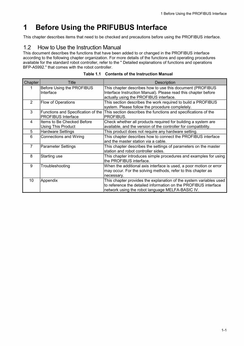
1 Before Using the PRIFUBUS Interface This chapter describes items that need to be checked and precautions before using the PROFIBUS interface. 1.2 How to Use the Instruction Manual This document describes the functions that have been added to or changed in the PROFIBUS interface according to the following chapter organization. For more details of the functions and operating procedures available for the standard robot controller, refer to the " Detailed explanations of functions and operations BFP-A5992." that comes with the robot controller.
Table 1.1 Contents of the Instruction Manual
Chapter Title Description 1 Before Using the PROFIBUS
Interface This chapter describes how to use this document (PROFIBUS Interface Instruction Manual). Please read this chapter before actually using the PROFIBUS interface.
2 Flow of Operations This section describes the work required to build a PROFIBUS system. Please follow the procedure completely.
3 Functions and Specification of the PROFIBUS Interface
This section describes the functions and specifications of the PROFIBUS.
4 Items to Be Checked Before Using This Product
Check whether all products required for building a system are available, and the version of the controller for compatibility.
5 Hardware Settings This product does not require any hardware setting. 6 Connections and Wiring This chapter describes how to connect the PROFIBUS interface
and the master station via a cable. 7 Parameter Settings This chapter describes the settings of parameters on the master
station and robot controller sides. 8 Starting use This chapter introduces simple procedures and examples for using
the PROFIBUS interface. 9 Troubleshooting When the additional axis interface is used, a poor motion or error
may occur. For the solving methods, refer to this chapter as necessary.
10 Appendix This chapter provides the explanation of the system variables used to reference the detailed information on the PROFIBUS interface network using the robot language MELFA-BASIC IV.

2 Flow of Operations
2-1
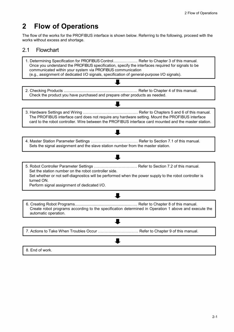
2 Flow of Operations The flow of the works for the PROFIBUS interface is shown below. Referring to the following, proceed with the works without excess and shortage. 2.1 Flowchart
1. Determining Specification for PROFIBUS Control...........…........ Refer to Chapter 3 of this manual. Once you understand the PROFIBUS specification, specify the interfaces required for signals to be communicated within your system via PROFIBUS communication (e.g., assignment of dedicated I/O signals, specification of general-purpose I/O signals).
2. Checking Products ...............................................…..........…… Refer to Chapter 4 of this manual. Check the product you have purchased and prepare other products as needed.
3. Hardware Settings and Wiring …………………………………… Refer to Chapters 5 and 6 of this manual.The PROFIBUS interface card does not require any hardware setting. Mount the PROFIBUS interface card to the robot controller. Wire between the PROFIBUS interface card mounted and the master station.
4. Master Station Parameter Settings ……………………………… Refer to Section 7.1 of this manual. Sets the signal assignment and the slave station number from the master station.
5. Robot Controller Parameter Settings …………………………… Refer to Section 7.2 of this manual. Set the station number on the robot controller side. Set whether or not self-diagnostics will be performed when the power supply to the robot controller is turned ON. Perform signal assignment of dedicated I/O.
6. Creating Robot Programs....................................................….. Refer to Chapter 8 of this manual. Create robot programs according to the specification determined in Operation 1 above and execute the automatic operation.
7. Actions to Take When Troubles Occur …………………….…… Refer to Chapter 9 of this manual.
8. End of work.

3 Functions and Specification of the PROFIBUS Interface
3-1
3 Functions and Specification of the PROFIBUS Interface
3.1 What Is PROFIBUS?
Field network PROFIBUS-DP(*1)
Partner manufacturers' devices
PROFIBUS interface card (this option)
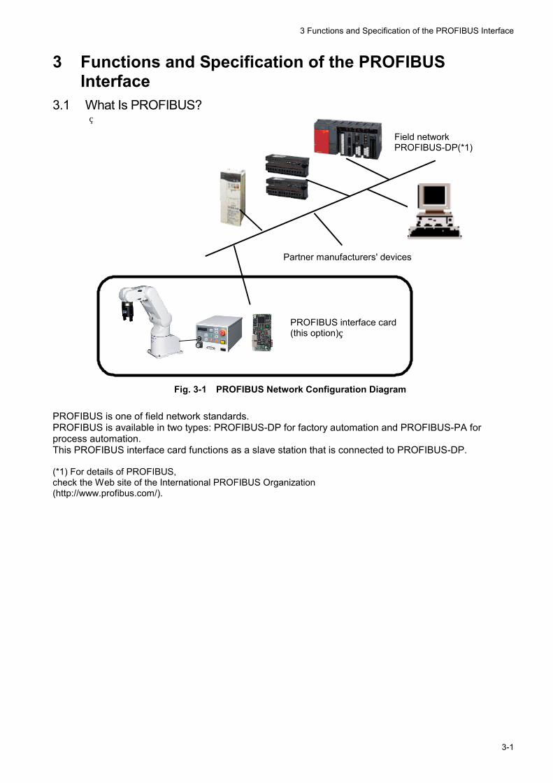
Fig. 3-1 PROFIBUS Network Configuration Diagram
PROFIBUS is one of field network standards. PROFIBUS is available in two types: PROFIBUS-DP for factory automation and PROFIBUS-PA for process automation. This PROFIBUS interface card functions as a slave station that is connected to PROFIBUS-DP. (*1) For details of PROFIBUS, check the Web site of the International PROFIBUS Organization (http://www.profibus.com/).
3 Functions and Specification of the PROFIBUS Interface
3-2
3.2 Specification of the PROFIBUS Interface Card The following sections describe the PROFIBUS interface card.
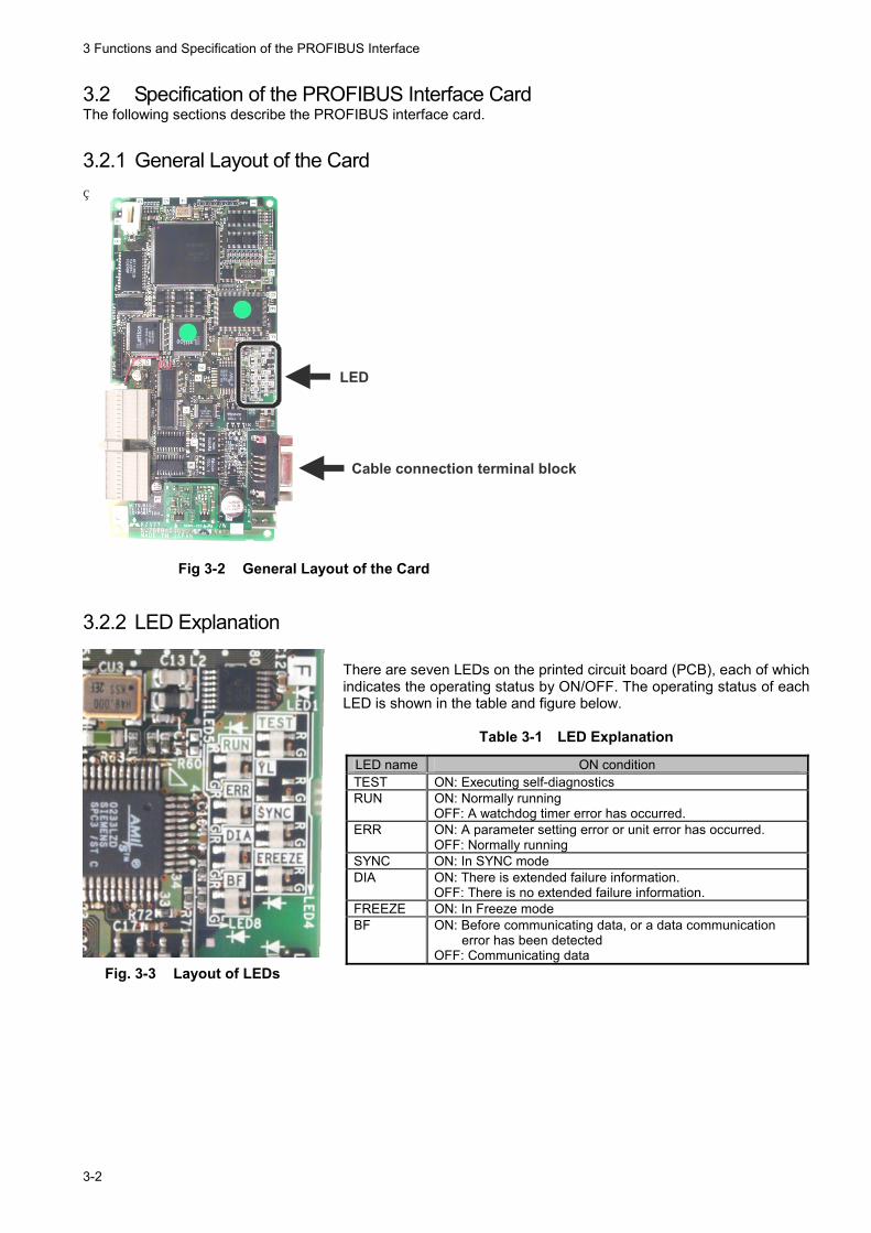
3.2.1 General Layout of the Card
Cable connection terminal block
LED
Fig 3-2 General Layout of the Card
3.2.2 LED Explanation There are seven LEDs on the printed circuit board (PCB), each of which indicates the operating status by ON/OFF. The operating status of each LED is shown in the table and figure below.
Table 3-1 LED Explanation
Fig. 3-3 Layout of LEDs
LED name ON condition TEST ON: Executing self-diagnostics RUN ON: Normally running
OFF: A watchdog timer error has occurred. ERR ON: A parameter setting error or unit error has occurred.
OFF: Normally running SYNC ON: In SYNC mode DIA ON: There is extended failure information.
OFF: There is no extended failure information. FREEZE ON: In Freeze mode BF ON: Before communicating data, or a data communication
error has been detected OFF: Communicating data
3 Functions and Specification of the PROFIBUS Interface
3-3
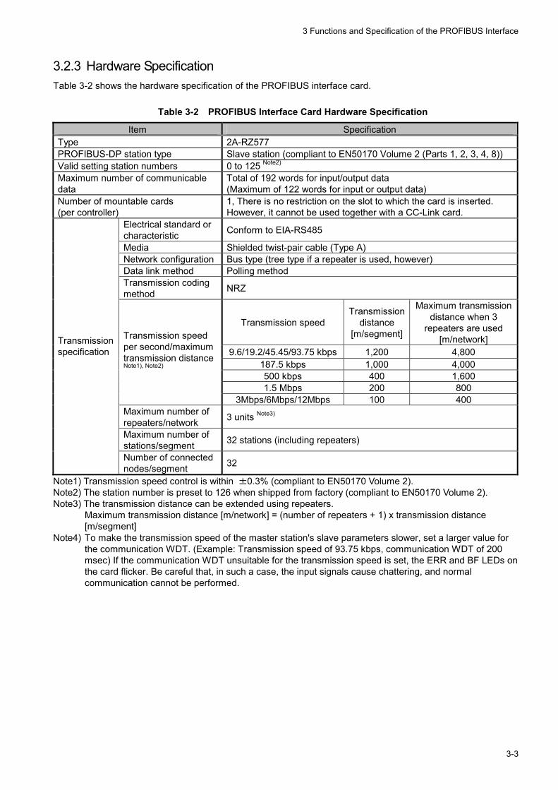
3.2.3 Hardware Specification Table 3-2 shows the hardware specification of the PROFIBUS interface card.
Table 3-2 PROFIBUS Interface Card Hardware Specification
Item Specification Type 2A-RZ577 PROFIBUS-DP station type Slave station (compliant to EN50170 Volume 2 (Parts 1, 2, 3, 4, 8)) Valid setting station numbers 0 to 125 Note2) Maximum number of communicable data
Total of 192 words for input/output data (Maximum of 122 words for input or output data)
Number of mountable cards (per controller)
1, There is no restriction on the slot to which the card is inserted. However, it cannot be used together with a CC-Link card.
Electrical standard or characteristic Conform to EIA-RS485
Media Shielded twist-pair cable (Type A) Network configuration Bus type (tree type if a repeater is used, however) Data link method Polling method Transmission coding method NRZ
Transmission speed Transmission
distance [m/segment]
Maximum transmission distance when 3
repeaters are used [m/network]
9.6/19.2/45.45/93.75 kbps 1,200 4,800 187.5 kbps 1,000 4,000 500 kbps 400 1,600 1.5 Mbps 200 800
Transmission speed per second/maximum transmission distance Note1), Note2)
3Mbps/6Mbps/12Mbps 100 400 Maximum number of repeaters/network 3 units Note3)
Maximum number of stations/segment 32 stations (including repeaters)
Transmission specification
Number of connected nodes/segment 32
Note1) Transmission speed control is within ±0.3% (compliant to EN50170 Volume 2). Note2) The station number is preset to 126 when shipped from factory (compliant to EN50170 Volume 2). Note3) The transmission distance can be extended using repeaters.
Maximum transmission distance [m/network] = (number of repeaters + 1) x transmission distance [m/segment]
Note4) To make the transmission speed of the master station's slave parameters slower, set a larger value for the communication WDT. (Example: Transmission speed of 93.75 kbps, communication WDT of 200 msec) If the communication WDT unsuitable for the transmission speed is set, the ERR and BF LEDs on the card flicker. Be careful that, in such a case, the input signals cause chattering, and normal communication cannot be performed.
3 Functions and Specification of the PROFIBUS Interface
3-4
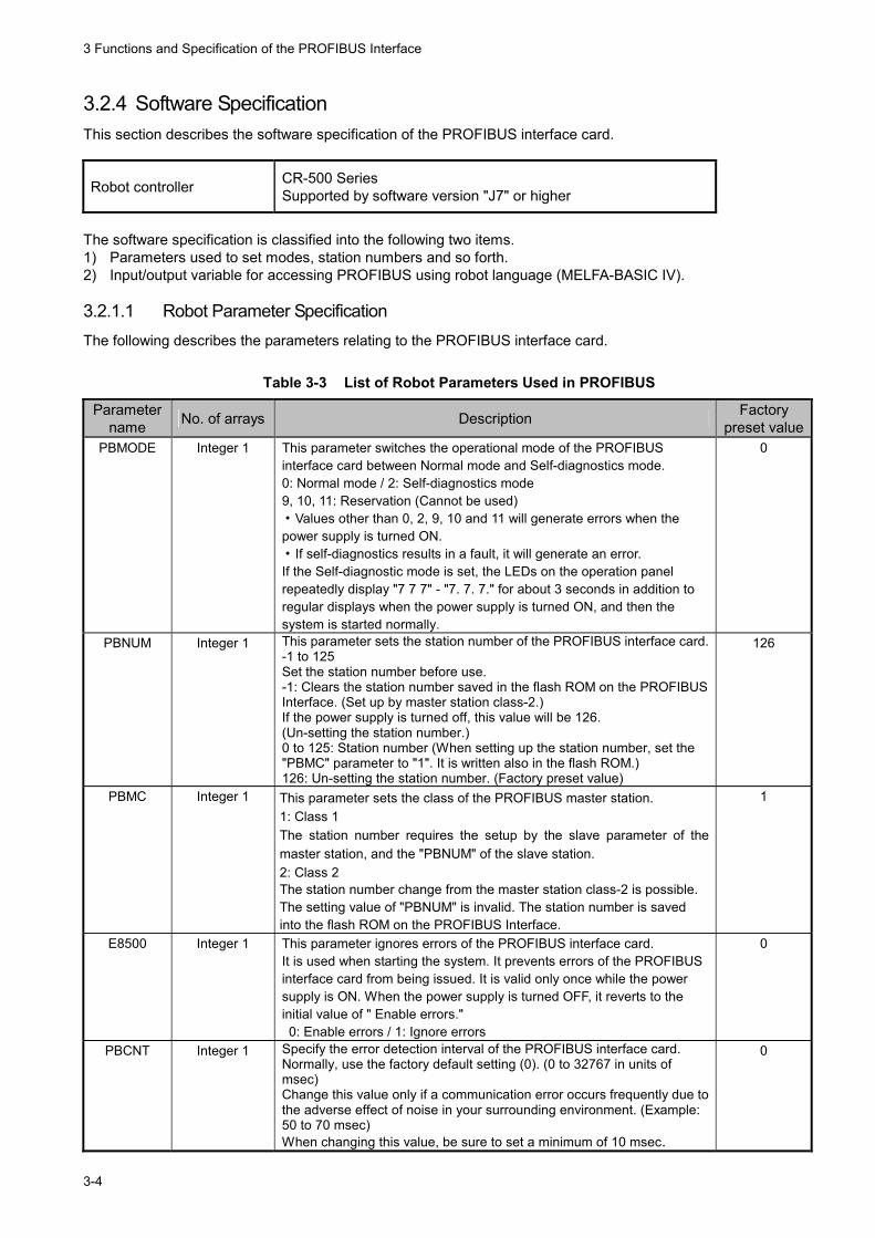
3.2.4 Software Specification This section describes the software specification of the PROFIBUS interface card.
Robot controller CR-500 Series Supported by software version "J7" or higher
The software specification is classified into the following two items. 1) Parameters used to set modes, station numbers and so forth. 2) Input/output variable for accessing PROFIBUS using robot language (MELFA-BASIC IV). 3.2.1.1 Robot Parameter Specification The following describes the parameters relating to the PROFIBUS interface card.
Table 3-3 List of Robot Parameters Used in PROFIBUS
Parameter name No. of arrays Description Factory
preset valuePBMODE Integer 1 This parameter switches the operational mode of the PROFIBUS
interface card between Normal mode and Self-diagnostics mode. 0: Normal mode / 2: Self-diagnostics mode 9, 10, 11: Reservation (Cannot be used) ・Values other than 0, 2, 9, 10 and 11 will generate errors when the power supply is turned ON. ・If self-diagnostics results in a fault, it will generate an error. If the Self-diagnostic mode is set, the LEDs on the operation panel repeatedly display "7 7 7" - "7. 7. 7." for about 3 seconds in addition to regular displays when the power supply is turned ON, and then the system is started normally.
0
PBNUM Integer 1 This parameter sets the station number of the PROFIBUS interface card. -1 to 125 Set the station number before use. -1: Clears the station number saved in the flash ROM on the PROFIBUS Interface. (Set up by master station class-2.) If the power supply is turned off, this value will be 126. (Un-setting the station number.) 0 to 125: Station number (When setting up the station number, set the "PBMC" parameter to "1". It is written also in the flash ROM.) 126: Un-setting the station number. (Factory preset value)
126
PBMC Integer 1 This parameter sets the class of the PROFIBUS master station. 1: Class 1 The station number requires the setup by the slave parameter of the master station, and the "PBNUM" of the slave station. 2: Class 2 The station number change from the master station class-2 is possible. The setting value of "PBNUM" is invalid. The station number is saved into the flash ROM on the PROFIBUS Interface.
1
E8500 Integer 1 This parameter ignores errors of the PROFIBUS interface card. It is used when starting the system. It prevents errors of the PROFIBUS interface card from being issued. It is valid only once while the power supply is ON. When the power supply is turned OFF, it reverts to the initial value of " Enable errors." 0: Enable errors / 1: Ignore errors
0
PBCNT Integer 1 Specify the error detection interval of the PROFIBUS interface card. Normally, use the factory default setting (0). (0 to 32767 in units of msec) Change this value only if a communication error occurs frequently due to the adverse effect of noise in your surrounding environment. (Example: 50 to 70 msec) When changing this value, be sure to set a minimum of 10 msec.
0
3 Functions and Specification of the PROFIBUS Interface
3-5
3.2.1.2 Specification Relating to Robot Language The following describes the robot language (MELFA-BASIC IV) relating to the PROFIBUS interface card.
Table 3-4 List of System Status Variables Used in PROFIBUS
Item Function Remarks M_IN Reads 1-bit data from the specified input signal. Example: IF M_IN(2000)=1 THEN M_OUT Writes 1-bit data to the specified output signal. Example: M_OUT(3000)=1 M_INB Reads 8-bit data from the specified input signal. Example: IF M_INB(2000)=7 THEN M_OUTB Writes 8-bit data to the specified output signal. Example: M_OUTB(3000)=&HFF M_INW Reads 16-bit data from the specified input signal. Example: IF M_INW(2500)=30000 THENM_OUTW Writes 16-bit data to the specified output signal. Example: M_OUTW(3500)=-30000
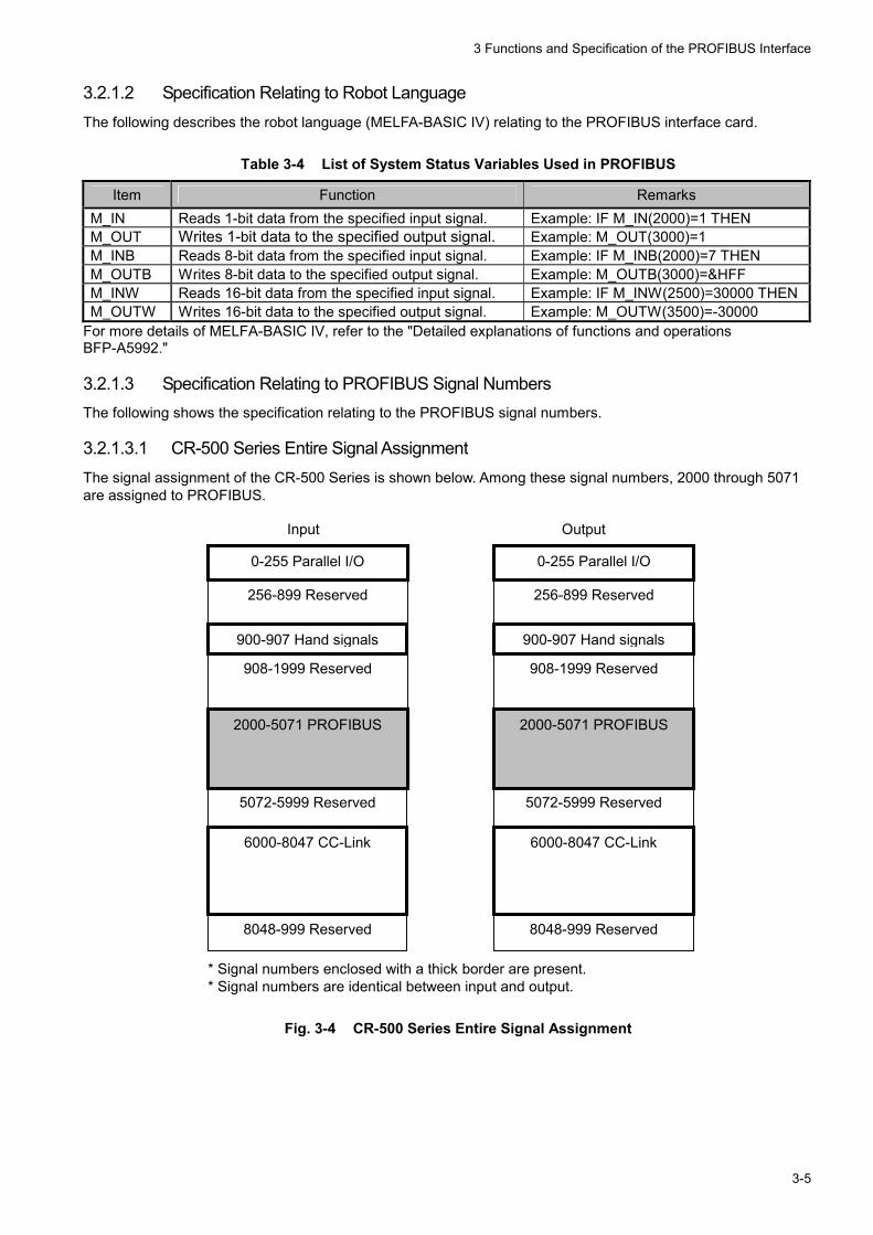
For more details of MELFA-BASIC IV, refer to the "Detailed explanations of functions and operations BFP-A5992." 3.2.1.3 Specification Relating to PROFIBUS Signal Numbers The following shows the specification relating to the PROFIBUS signal numbers. 3.2.1.3.1 CR-500 Series Entire Signal Assignment The signal assignment of the CR-500 Series is shown below. Among these signal numbers, 2000 through 5071 are assigned to PROFIBUS. Input Output
* Signal numbers enclosed with a thick border are present. * Signal numbers are identical between input and output.
Fig. 3-4 CR-500 Series Entire Signal Assignment
0-255 Parallel I/O
256-899 Reserved
2000-5071 PROFIBUS
5072-5999 Reserved
6000-8047 CC-Link
900-907 Hand signals
908-1999 Reserved
8048-999 Reserved
0-255 Parallel I/O
256-899 Reserved
2000-5071 PROFIBUS
5072-5999 Reserved
6000-8047 CC-Link
900-907 Hand signals
908-1999 Reserved
8048-999 Reserved
3 Functions and Specification of the PROFIBUS Interface
3-6
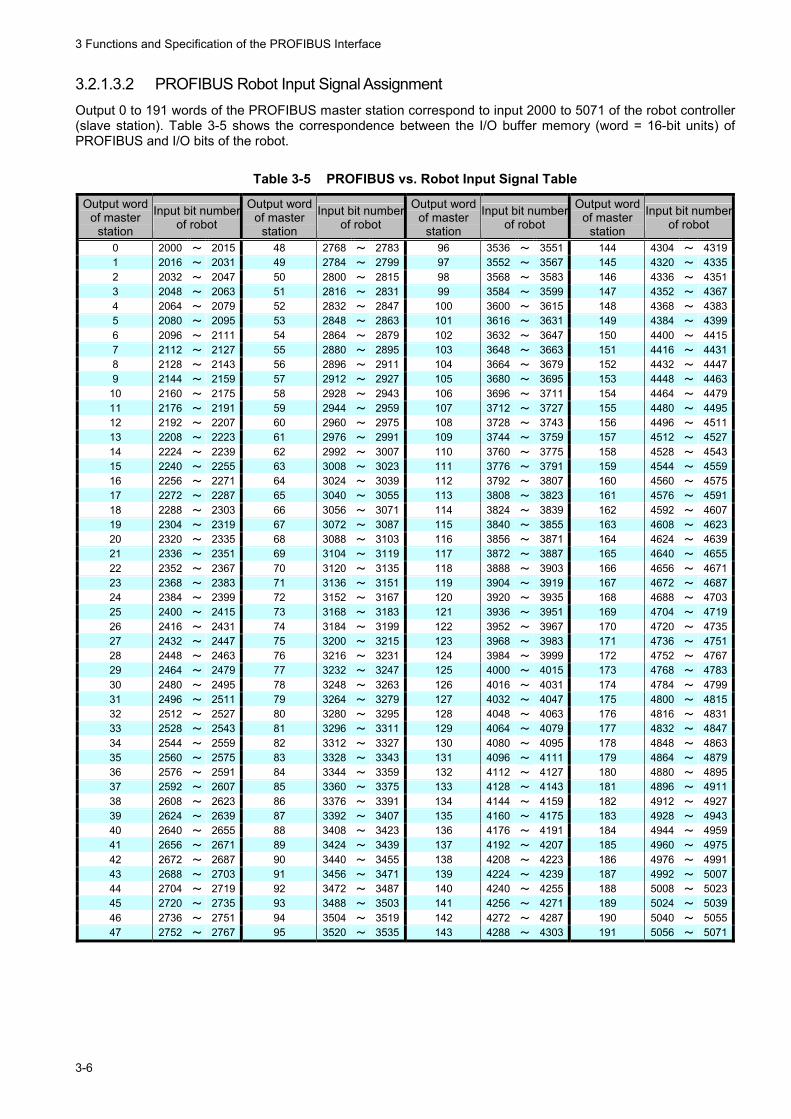
3.2.1.3.2 PROFIBUS Robot Input Signal Assignment Output 0 to 191 words of the PROFIBUS master station correspond to input 2000 to 5071 of the robot controller (slave station). Table 3-5 shows the correspondence between the I/O buffer memory (word = 16-bit units) of PROFIBUS and I/O bits of the robot.
Table 3-5 PROFIBUS vs. Robot Input Signal Table
Output word of master
station
Input bit numberof robot
Output word of master
station
Input bit numberof robot
Output word of master
station
Input bit numberof robot
Output word of master
station
Input bit numberof robot
0 2000 ~ 2015 48 2768 ~ 2783 96 3536 ~ 3551 144 4304 ~ 43191 2016 ~ 2031 49 2784 ~ 2799 97 3552 ~ 3567 145 4320 ~ 43352 2032 ~ 2047 50 2800 ~ 2815 98 3568 ~ 3583 146 4336 ~ 43513 2048 ~ 2063 51 2816 ~ 2831 99 3584 ~ 3599 147 4352 ~ 43674 2064 ~ 2079 52 2832 ~ 2847 100 3600 ~ 3615 148 4368 ~ 43835 2080 ~ 2095 53 2848 ~ 2863 101 3616 ~ 3631 149 4384 ~ 43996 2096 ~ 2111 54 2864 ~ 2879 102 3632 ~ 3647 150 4400 ~ 44157 2112 ~ 2127 55 2880 ~ 2895 103 3648 ~ 3663 151 4416 ~ 44318 2128 ~ 2143 56 2896 ~ 2911 104 3664 ~ 3679 152 4432 ~ 44479 2144 ~ 2159 57 2912 ~ 2927 105 3680 ~ 3695 153 4448 ~ 4463
10 2160 ~ 2175 58 2928 ~ 2943 106 3696 ~ 3711 154 4464 ~ 447911 2176 ~ 2191 59 2944 ~ 2959 107 3712 ~ 3727 155 4480 ~ 449512 2192 ~ 2207 60 2960 ~ 2975 108 3728 ~ 3743 156 4496 ~ 451113 2208 ~ 2223 61 2976 ~ 2991 109 3744 ~ 3759 157 4512 ~ 452714 2224 ~ 2239 62 2992 ~ 3007 110 3760 ~ 3775 158 4528 ~ 454315 2240 ~ 2255 63 3008 ~ 3023 111 3776 ~ 3791 159 4544 ~ 455916 2256 ~ 2271 64 3024 ~ 3039 112 3792 ~ 3807 160 4560 ~ 457517 2272 ~ 2287 65 3040 ~ 3055 113 3808 ~ 3823 161 4576 ~ 459118 2288 ~ 2303 66 3056 ~ 3071 114 3824 ~ 3839 162 4592 ~ 460719 2304 ~ 2319 67 3072 ~ 3087 115 3840 ~ 3855 163 4608 ~ 462320 2320 ~ 2335 68 3088 ~ 3103 116 3856 ~ 3871 164 4624 ~ 463921 2336 ~ 2351 69 3104 ~ 3119 117 3872 ~ 3887 165 4640 ~ 465522 2352 ~ 2367 70 3120 ~ 3135 118 3888 ~ 3903 166 4656 ~ 467123 2368 ~ 2383 71 3136 ~ 3151 119 3904 ~ 3919 167 4672 ~ 468724 2384 ~ 2399 72 3152 ~ 3167 120 3920 ~ 3935 168 4688 ~ 470325 2400 ~ 2415 73 3168 ~ 3183 121 3936 ~ 3951 169 4704 ~ 471926 2416 ~ 2431 74 3184 ~ 3199 122 3952 ~ 3967 170 4720 ~ 473527 2432 ~ 2447 75 3200 ~ 3215 123 3968 ~ 3983 171 4736 ~ 475128 2448 ~ 2463 76 3216 ~ 3231 124 3984 ~ 3999 172 4752 ~ 476729 2464 ~ 2479 77 3232 ~ 3247 125 4000 ~ 4015 173 4768 ~ 478330 2480 ~ 2495 78 3248 ~ 3263 126 4016 ~ 4031 174 4784 ~ 479931 2496 ~ 2511 79 3264 ~ 3279 127 4032 ~ 4047 175 4800 ~ 481532 2512 ~ 2527 80 3280 ~ 3295 128 4048 ~ 4063 176 4816 ~ 483133 2528 ~ 2543 81 3296 ~ 3311 129 4064 ~ 4079 177 4832 ~ 484734 2544 ~ 2559 82 3312 ~ 3327 130 4080 ~ 4095 178 4848 ~ 486335 2560 ~ 2575 83 3328 ~ 3343 131 4096 ~ 4111 179 4864 ~ 487936 2576 ~ 2591 84 3344 ~ 3359 132 4112 ~ 4127 180 4880 ~ 489537 2592 ~ 2607 85 3360 ~ 3375 133 4128 ~ 4143 181 4896 ~ 491138 2608 ~ 2623 86 3376 ~ 3391 134 4144 ~ 4159 182 4912 ~ 492739 2624 ~ 2639 87 3392 ~ 3407 135 4160 ~ 4175 183 4928 ~ 494340 2640 ~ 2655 88 3408 ~ 3423 136 4176 ~ 4191 184 4944 ~ 495941 2656 ~ 2671 89 3424 ~ 3439 137 4192 ~ 4207 185 4960 ~ 497542 2672 ~ 2687 90 3440 ~ 3455 138 4208 ~ 4223 186 4976 ~ 499143 2688 ~ 2703 91 3456 ~ 3471 139 4224 ~ 4239 187 4992 ~ 500744 2704 ~ 2719 92 3472 ~ 3487 140 4240 ~ 4255 188 5008 ~ 502345 2720 ~ 2735 93 3488 ~ 3503 141 4256 ~ 4271 189 5024 ~ 503946 2736 ~ 2751 94 3504 ~ 3519 142 4272 ~ 4287 190 5040 ~ 505547 2752 ~ 2767 95 3520 ~ 3535 143 4288 ~ 4303 191 5056 ~ 5071
3 Functions and Specification of the PROFIBUS Interface
3-7
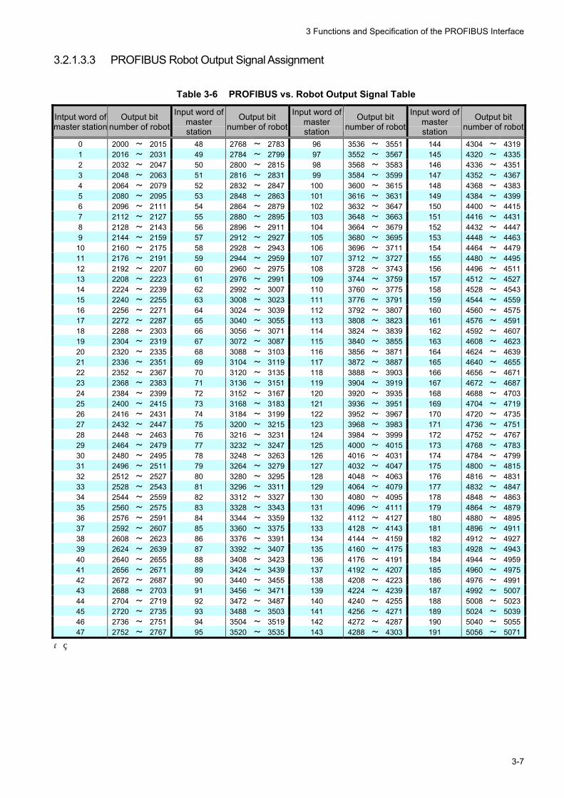
3.2.1.3.3 PROFIBUS Robot Output Signal Assignment
Table 3-6 PROFIBUS vs. Robot Output Signal Table
Intput word of master station
Output bit number of robot
Input word of master station
Output bit number of robot
Input word of master station
Output bit number of robot
Input word of master station
Output bit number of robot
0 2000 ~ 2015 48 2768 ~ 2783 96 3536 ~ 3551 144 4304 ~ 43191 2016 ~ 2031 49 2784 ~ 2799 97 3552 ~ 3567 145 4320 ~ 43352 2032 ~ 2047 50 2800 ~ 2815 98 3568 ~ 3583 146 4336 ~ 43513 2048 ~ 2063 51 2816 ~ 2831 99 3584 ~ 3599 147 4352 ~ 43674 2064 ~ 2079 52 2832 ~ 2847 100 3600 ~ 3615 148 4368 ~ 43835 2080 ~ 2095 53 2848 ~ 2863 101 3616 ~ 3631 149 4384 ~ 43996 2096 ~ 2111 54 2864 ~ 2879 102 3632 ~ 3647 150 4400 ~ 44157 2112 ~ 2127 55 2880 ~ 2895 103 3648 ~ 3663 151 4416 ~ 44318 2128 ~ 2143 56 2896 ~ 2911 104 3664 ~ 3679 152 4432 ~ 44479 2144 ~ 2159 57 2912 ~ 2927 105 3680 ~ 3695 153 4448 ~ 446310 2160 ~ 2175 58 2928 ~ 2943 106 3696 ~ 3711 154 4464 ~ 447911 2176 ~ 2191 59 2944 ~ 2959 107 3712 ~ 3727 155 4480 ~ 449512 2192 ~ 2207 60 2960 ~ 2975 108 3728 ~ 3743 156 4496 ~ 451113 2208 ~ 2223 61 2976 ~ 2991 109 3744 ~ 3759 157 4512 ~ 452714 2224 ~ 2239 62 2992 ~ 3007 110 3760 ~ 3775 158 4528 ~ 454315 2240 ~ 2255 63 3008 ~ 3023 111 3776 ~ 3791 159 4544 ~ 455916 2256 ~ 2271 64 3024 ~ 3039 112 3792 ~ 3807 160 4560 ~ 457517 2272 ~ 2287 65 3040 ~ 3055 113 3808 ~ 3823 161 4576 ~ 459118 2288 ~ 2303 66 3056 ~ 3071 114 3824 ~ 3839 162 4592 ~ 460719 2304 ~ 2319 67 3072 ~ 3087 115 3840 ~ 3855 163 4608 ~ 462320 2320 ~ 2335 68 3088 ~ 3103 116 3856 ~ 3871 164 4624 ~ 463921 2336 ~ 2351 69 3104 ~ 3119 117 3872 ~ 3887 165 4640 ~ 465522 2352 ~ 2367 70 3120 ~ 3135 118 3888 ~ 3903 166 4656 ~ 467123 2368 ~ 2383 71 3136 ~ 3151 119 3904 ~ 3919 167 4672 ~ 468724 2384 ~ 2399 72 3152 ~ 3167 120 3920 ~ 3935 168 4688 ~ 470325 2400 ~ 2415 73 3168 ~ 3183 121 3936 ~ 3951 169 4704 ~ 471926 2416 ~ 2431 74 3184 ~ 3199 122 3952 ~ 3967 170 4720 ~ 473527 2432 ~ 2447 75 3200 ~ 3215 123 3968 ~ 3983 171 4736 ~ 475128 2448 ~ 2463 76 3216 ~ 3231 124 3984 ~ 3999 172 4752 ~ 476729 2464 ~ 2479 77 3232 ~ 3247 125 4000 ~ 4015 173 4768 ~ 478330 2480 ~ 2495 78 3248 ~ 3263 126 4016 ~ 4031 174 4784 ~ 479931 2496 ~ 2511 79 3264 ~ 3279 127 4032 ~ 4047 175 4800 ~ 481532 2512 ~ 2527 80 3280 ~ 3295 128 4048 ~ 4063 176 4816 ~ 483133 2528 ~ 2543 81 3296 ~ 3311 129 4064 ~ 4079 177 4832 ~ 484734 2544 ~ 2559 82 3312 ~ 3327 130 4080 ~ 4095 178 4848 ~ 486335 2560 ~ 2575 83 3328 ~ 3343 131 4096 ~ 4111 179 4864 ~ 487936 2576 ~ 2591 84 3344 ~ 3359 132 4112 ~ 4127 180 4880 ~ 489537 2592 ~ 2607 85 3360 ~ 3375 133 4128 ~ 4143 181 4896 ~ 491138 2608 ~ 2623 86 3376 ~ 3391 134 4144 ~ 4159 182 4912 ~ 492739 2624 ~ 2639 87 3392 ~ 3407 135 4160 ~ 4175 183 4928 ~ 494340 2640 ~ 2655 88 3408 ~ 3423 136 4176 ~ 4191 184 4944 ~ 495941 2656 ~ 2671 89 3424 ~ 3439 137 4192 ~ 4207 185 4960 ~ 497542 2672 ~ 2687 90 3440 ~ 3455 138 4208 ~ 4223 186 4976 ~ 499143 2688 ~ 2703 91 3456 ~ 3471 139 4224 ~ 4239 187 4992 ~ 500744 2704 ~ 2719 92 3472 ~ 3487 140 4240 ~ 4255 188 5008 ~ 502345 2720 ~ 2735 93 3488 ~ 3503 141 4256 ~ 4271 189 5024 ~ 503946 2736 ~ 2751 94 3504 ~ 3519 142 4272 ~ 4287 190 5040 ~ 505547 2752 ~ 2767 95 3520 ~ 3535 143 4288 ~ 4303 191 5056 ~ 5071
・
3 Functions and Specification of the PROFIBUS Interface
3-8
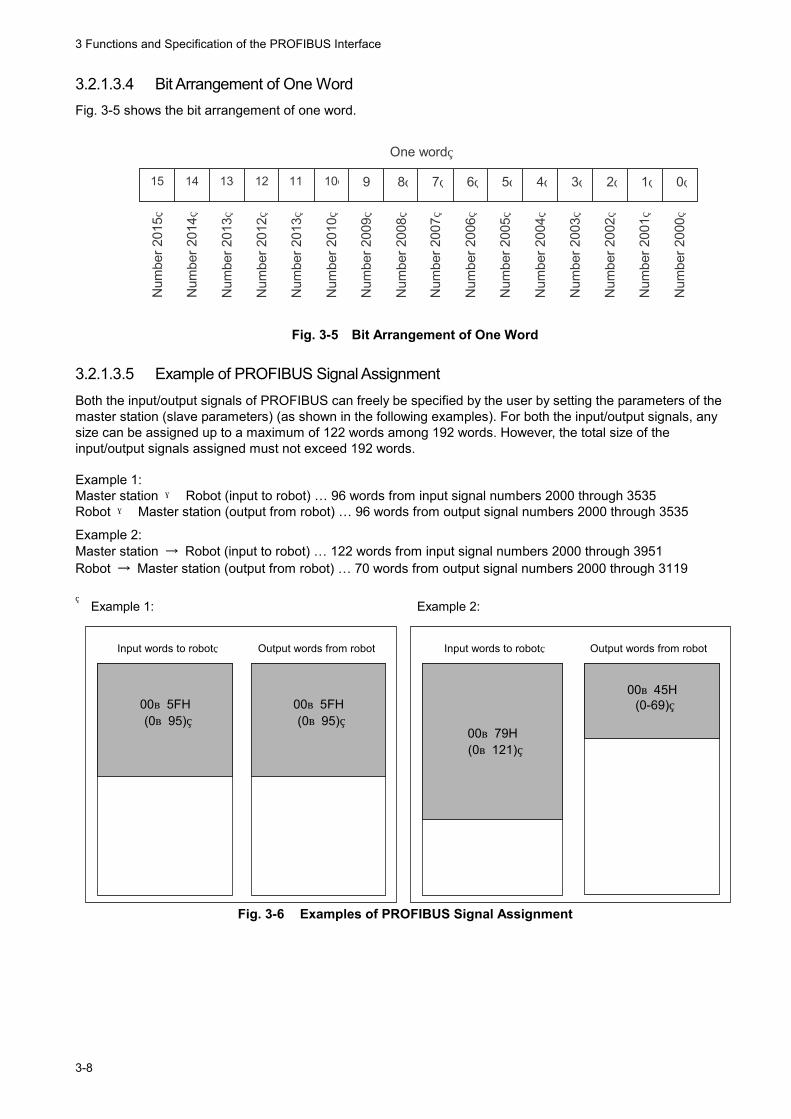
3.2.1.3.4 Bit Arrangement of One Word Fig. 3-5 shows the bit arrangement of one word.
15 14 13 12 11
10 9 8 7 6 5 4 3 2 1 0
One word N
umbe
r 201
5
Num
ber 2
014
Num
ber 2
013
Num
ber 2
012
Num
ber 2
013
Num
ber 2
010
Num
ber 2
009
Num
ber 2
008
Num
ber 2
007
Num
ber 2
006
Num
ber 2
005
Num
ber 2
004
Num
ber 2
003
Num
ber 2
002
Num
ber 2
001
Num
ber 2
000
Fig. 3-5 Bit Arrangement of One Word
3.2.1.3.5 Example of PROFIBUS Signal Assignment Both the input/output signals of PROFIBUS can freely be specified by the user by setting the parameters of the master station (slave parameters) (as shown in the following examples). For both the input/output signals, any size can be assigned up to a maximum of 122 words among 192 words. However, the total size of the input/output signals assigned must not exceed 192 words. Example 1: Master station → Robot (input to robot) … 96 words from input signal numbers 2000 through 3535 Robot → Master station (output from robot) … 96 words from output signal numbers 2000 through 3535
Example 2: Master station → Robot (input to robot) … 122 words from input signal numbers 2000 through 3951 Robot → Master station (output from robot) … 70 words from output signal numbers 2000 through 3119
Input words to robot Output words from robot Input words to robot Output words from robot
Example 1: Example 2:
00~79H (0~121)
00~45H
(0-69)
00~5FH (0~95)
00~5FH (0~95)
Fig. 3-6 Examples of PROFIBUS Signal Assignment
4 Items to Be Checked Before Using This Product (Procedure 1)
4-1
4 Items to Be Checked Before Using This Product (Procedure 1)
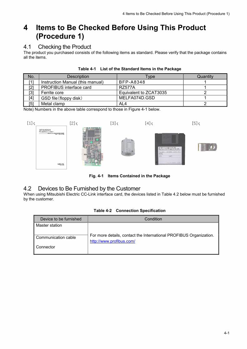
4.1 Checking the Product The product you purchased consists of the following items as standard. Please verify that the package contains all the items.
Table 4-1 List of the Standard Items in the Package
No. Description Type Quantity [1] Instruction Manual (this manual) BFP-A8348 1 [2] PROFIBUS interface card RZ577A 1 [3] Ferrite core Equivalent to ZCAT3035 2 [4] GSD file(floppy disk) MELFA074D.GSD 1 [5] Metal clamp AL4 2
Note) Numbers in the above table correspond to those in Figure 4-1 below.
[2] [1] [3]
[4] [5]
Fig. 4-1 Items Contained in the Package
4.2 Devices to Be Furnished by the Customer When using Mitsubishi Electric CC-Link interface card, the devices listed in Table 4.2 below must be furnished by the customer.
Table 4-2 Connection Specification
Device to be furnished Condition Master station
Communication cable
Connector
For more details, contact the International PROFIBUS Organization. http://www.profibus.com/


5 Hardware Settings
5-1
5 Hardware Settings No hardware setting is required for the PROFIBUS interface card. All settings are performed using parameters on both the master station and robot controller sides.

6 Connection and Wiring (Procedure 2)
6-1
6 Connection and Wiring (Procedure 2) 6.1 Mounting the PROFIBUS Interface Card to the Main Body For details of mounting method, refer to "Installing Optional Devices" in "Controller Setup and Basic Operations to Maintenance" of each controller's instruction manual.
Table 6-1 Robot Controller Installation Method by Type
Controller type Installation method Number of Instruction Manual Remarks
CR1 1) Install the extension option box.
2) Install the PROFIBUS interface card.
BFP-A8054 There is no restriction on installation slots. The PROFIBUS interface card can be installed into any of slots 1 through 3. * As for a PROFIBUS cable connector, use right-angled type (90 degree cable outlet).
CR2A/CR2B Install the PROFIBUS interface card into an option slot inside the controller.
BFP-A5991 There is no restriction on installation slots. The PROFIBUS interface card can be installed into any of slots 1 through 3. * As for a PROFIBUS cable connector, use right-angled type (90 degree cable outlet).
CR2 BFP-A5991 There is no restriction on installation slots. The PROFIBUS interface card can be installed into either slot 1 or 2.
CR3 BFP-A8324
CR4/CR7/CR8
Install the PROFIBUS interface card into an option slot of the R6xCPU unit.
BFP-A8077
There is no restriction on installation slots. The PROFIBUS interface card can be installed into either slot 1 or 2.
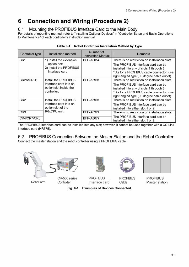
The PROFIBUS interface card can be installed into any slot; however, it cannot be used together with a CC-Link interface card (HR575). 6.2 PROFIBUS Connection Between the Master Station and the Robot Controller Connect the master station and the robot controller using a PROFIBUS cable.
PROFIBUS Interface card
PROFIBUS Cable
CR-500 series Controller Robot arm
PROFIBUS Master station
Fig. 6-1 Examples of Devices Connected
6 Connection and Wiring (Procedure 2)
6-2
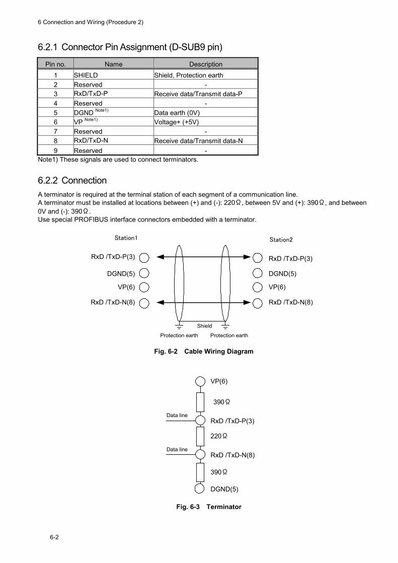
6.2.1 Connector Pin Assignment (D-SUB9 pin)
Pin no. Name Description 1 SHIELD Shield, Protection earth 2 Reserved - 3 RxD/TxD-P Receive data/Transmit data-P 4 Reserved - 5 DGND Note1) Data earth (0V) 6 VP Note1) Voltage+ (+5V) 7 Reserved - 8 RxD/TxD-N Receive data/Transmit data-N 9 Reserved -
Note1) These signals are used to connect terminators.
6.2.2 Connection A terminator is required at the terminal station of each segment of a communication line. A terminator must be installed at locations between (+) and (-): 220Ω, between 5V and (+): 390Ω, and between 0V and (-): 390Ω. Use special PROFIBUS interface connectors embedded with a terminator.
RxD /TxD-P(3)
DGND(5)
VP(6)
RxD /TxD-N(8)
Shield
Protection earth
RxD /TxD-P(3)
DGND(5)
VP(6)
RxD /TxD-N(8)
Station2Station1
Protection earth
Fig. 6-2 Cable Wiring Diagram
VP(6)
DGND(5)
RxD /TxD-P(3)
RxD /TxD-N(8)
390Ω
220Ω
390Ω
Data line
Data line
Fig. 6-3 Terminator
6 Connection and Wiring (Procedure 2)
6-3
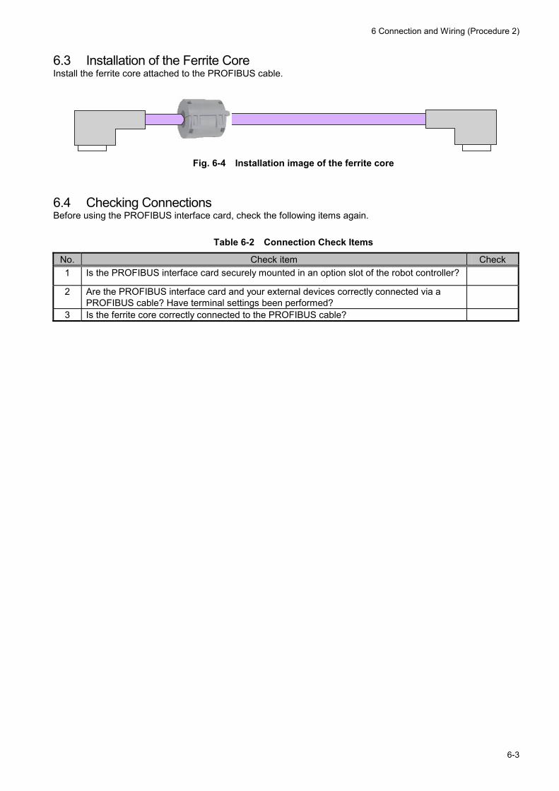
6.3 Installation of the Ferrite Core Install the ferrite core attached to the PROFIBUS cable.
Fig. 6-4 Installation image of the ferrite core
6.4 Checking Connections Before using the PROFIBUS interface card, check the following items again.
Table 6-2 Connection Check Items
No. Check item Check 1 Is the PROFIBUS interface card securely mounted in an option slot of the robot controller?
2 Are the PROFIBUS interface card and your external devices correctly connected via a PROFIBUS cable? Have terminal settings been performed?
3 Is the ferrite core correctly connected to the PROFIBUS cable?

7 Parameter Settings (Procedure 3)
7-1
7 Parameter Settings (Procedure 3) This chapter describes the settings of parameters on the master station and the robot controller. 7.1 Parameter Settings on the Master Station Side Set the parameters of the master station by referring to the applicable manual of the master station device.
1) Examine the number of WORD which will be assigned to robot controllers, and set the parameter of master station.
2) Set the station number of the robot (slave side) to the master station's parameter. Examine how many words will be assigned to the robot controller, then set it in a parameter of the master station. Because there are several types of master station devices, assign the applicable number of words to the robot controller according to your system configuration. You can set the byte swap of word data. Set it if you want to swap upper and lower bytes.
7 Parameter Settings (Procedure 3)
7-2
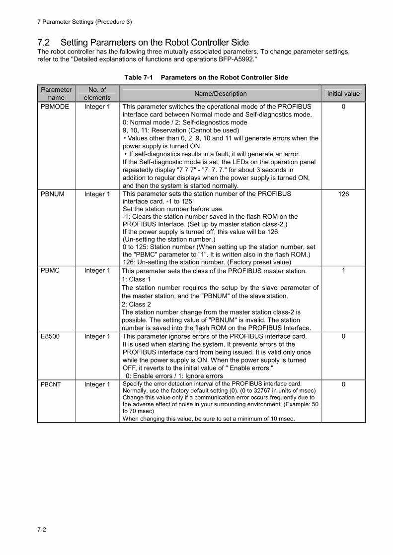
7.2 Setting Parameters on the Robot Controller Side The robot controller has the following three mutually associated parameters. To change parameter settings, refer to the "Detailed explanations of functions and operations BFP-A5992."
Table 7-1 Parameters on the Robot Controller Side
Parameter name
No. of elements Name/Description Initial value
PBMODE Integer 1 This parameter switches the operational mode of the PROFIBUS interface card between Normal mode and Self-diagnostics mode. 0: Normal mode / 2: Self-diagnostics mode 9, 10, 11: Reservation (Cannot be used) ・Values other than 0, 2, 9, 10 and 11 will generate errors when the power supply is turned ON. ・If self-diagnostics results in a fault, it will generate an error. If the Self-diagnostic mode is set, the LEDs on the operation panel repeatedly display "7 7 7" - "7. 7. 7." for about 3 seconds in addition to regular displays when the power supply is turned ON, and then the system is started normally.
0
PBNUM Integer 1 This parameter sets the station number of the PROFIBUS interface card. -1 to 125 Set the station number before use. -1: Clears the station number saved in the flash ROM on the PROFIBUS Interface. (Set up by master station class-2.) If the power supply is turned off, this value will be 126. (Un-setting the station number.) 0 to 125: Station number (When setting up the station number, set the "PBMC" parameter to "1". It is written also in the flash ROM.) 126: Un-setting the station number. (Factory preset value)
126
PBMC Integer 1 This parameter sets the class of the PROFIBUS master station. 1: Class 1 The station number requires the setup by the slave parameter of the master station, and the "PBNUM" of the slave station. 2: Class 2 The station number change from the master station class-2 is possible. The setting value of "PBNUM" is invalid. The station number is saved into the flash ROM on the PROFIBUS Interface.
1
E8500 Integer 1 This parameter ignores errors of the PROFIBUS interface card. It is used when starting the system. It prevents errors of the PROFIBUS interface card from being issued. It is valid only once while the power supply is ON. When the power supply is turned OFF, it reverts to the initial value of " Enable errors." 0: Enable errors / 1: Ignore errors
0
PBCNT Integer 1 Specify the error detection interval of the PROFIBUS interface card. Normally, use the factory default setting (0). (0 to 32767 in units of msec) Change this value only if a communication error occurs frequently due to the adverse effect of noise in your surrounding environment. (Example: 50 to 70 msec) When changing this value, be sure to set a minimum of 10 msec.
0
7 Parameter Settings (Procedure 3)
7-3
7.2.1 PROFIBUS Mode Setting Parameter (PBMODE) The PBMODE parameter sets whether the PROFIBUS card will start after performing self-diagnostics or without performing it when the power supply to the robot controller is turned ON. When in the Self-diagnostics mode, the power supply ON processing time prolongs by about 3 seconds.
7.2.2 PROFIBUS Station Number Setting Parameter (PBNUM) The PBNUM parameter sets the station number of PROFIBUS. The initial value is 126. Please be careful not to use a station number already used by other devices when changing it.
7.2.3 PROFIBUS Master Station Class Setting Parameter (PBMC) The PBMC parameter sets the class of master station side. The initial setting is class-1. Change this value if using by class-2.
7.2.4 PROFIBUS Error Ignore Parameter (E8500) The E8500 parameter prevents the generation of PROFIBUS related errors from being issued while mounting and operating a PROFIBUS card to the robot when the master station has not been adjusted or set. If this parameter is set to 1 while an error in 8500's is being generated, the error can be reset. Thereafter, no more errors in 8500's will be generated. This parameter takes effect immediately after its value is changed. If the power supply is turned ON/OFF once in order to prevent PROFIBUS communication errors from not being able to be detected in case you forgot to set this parameter, the value of this parameter reverts to the initial value, thereby detecting errors again.
7.2.5 PROFIBUS Error Detection Interval Parameter (PBCNT) Normally, use this parameter with the factory default setting (0). Change this value only if a communication error occurs frequently due to the adverse effect of noise in your surrounding environment. Setting 50 to 70 msec is sufficient in normal circumstances. If an excessively large value is set, the robot controller will not be able to detect errors if the PROFIBUS interface card generates errors intermittently. Pay extra attention when setting this value. If a value of 10 or larger is set, the controller will generate an error only if the controller detects an error in the PROFIBUS interface card continuously for the designated duration. If an error does not occur continuously, the controller will not generate an error. If a value less than 10 is set, the controller immediately issues an error upon detecting an error in the PROFIBUS interface card.
7 Parameter Settings (Procedure 3)
7-4
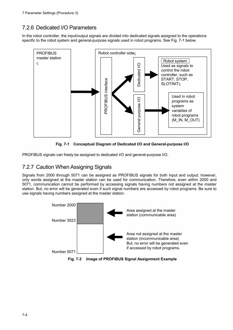
7.2.6 Dedicated I/O Parameters In the robot controller, the input/output signals are divided into dedicated signals assigned to the operations specific to the robot system and general-purpose signals used in robot programs. See Fig. 7-1 below.
Robot controller side PROFIBUS master station Robot system
Used as signals to control the robot controller, such as START, STOP, SLOTINIT
Used in robot programs as system variables of robot programs (M_IN, M_OUT)
PRO
FIBU
S in
terfa
ce
Ded
icat
ed I/
O
Gen
eral
pur
pose
I/O
Fig. 7-1 Conceptual Diagram of Dedicated I/O and General-purpose I/O PROFIBUS signals can freely be assigned to dedicated I/O and general-purpose I/O.
7.2.7 Caution When Assigning Signals Signals from 2000 through 5071 can be assigned as PROFIBUS signals for both input and output; however, only words assigned at the master station can be used for communication. Therefore, even within 2000 and 5071, communication cannot be performed by accessing signals having numbers not assigned at the master station. But, no error will be generated even if such signal numbers are accessed by robot programs. Be sure to use signals having numbers assigned at the master station.
Number 2000
Number 3023
Number 5071
Area assigned at the master station (communicable area)
Area not assigned at the master station (incommunicable area) But, no error will be generated even if accessed by robot programs.
Fig. 7-2 Image of PROFIBUS Signal Assignment Example
8 Starting use
8-1
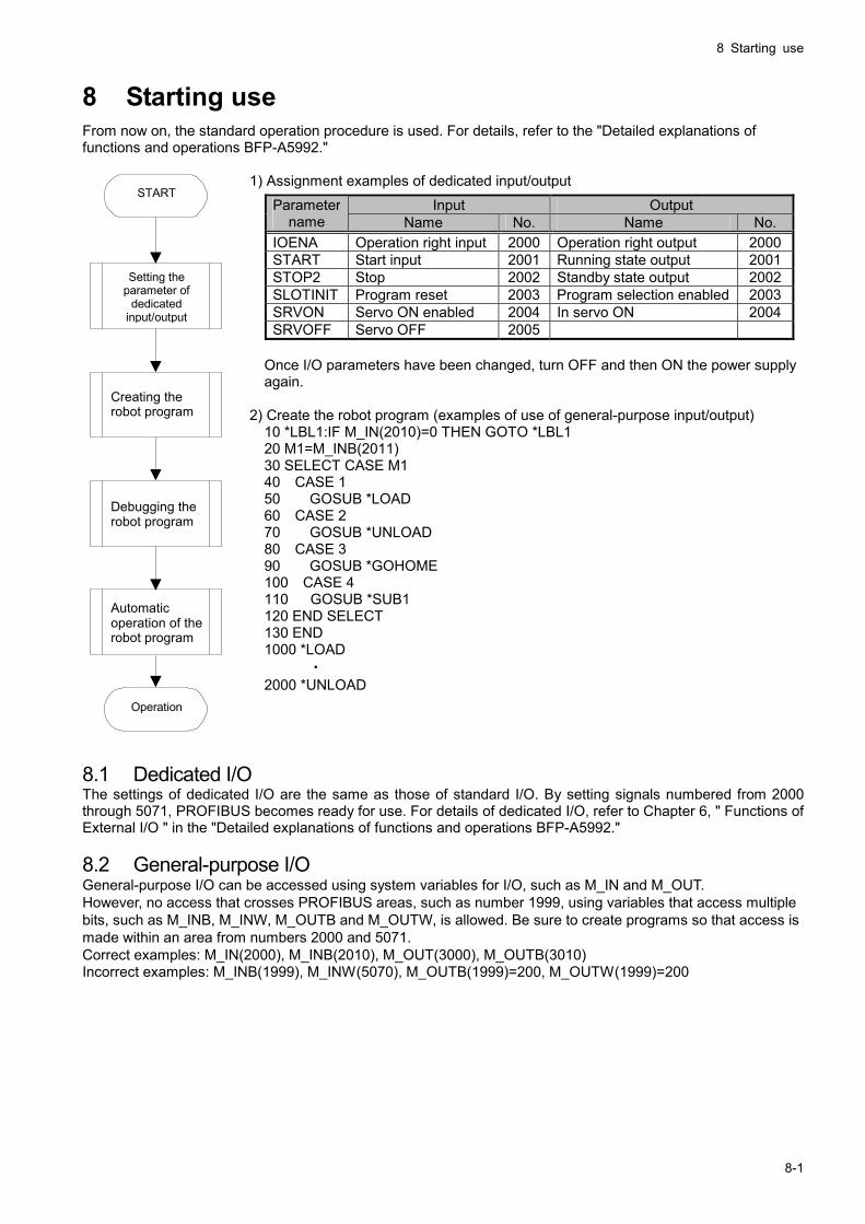
8 Starting use From now on, the standard operation procedure is used. For details, refer to the "Detailed explanations of functions and operations BFP-A5992."
1) Assignment examples of dedicated input/output
Once I/O parameters have been changed, turn OFF and then ON the power supply again.
2) Create the robot program (examples of use of general-purpose input/output)
10 *LBL1:IF M_IN(2010)=0 THEN GOTO *LBL1 20 M1=M_INB(2011) 30 SELECT CASE M1 40 CASE 1 50 GOSUB *LOAD 60 CASE 2 70 GOSUB *UNLOAD 80 CASE 3 90 GOSUB *GOHOME 100 CASE 4 110 GOSUB *SUB1 120 END SELECT 130 END 1000 *LOAD ・ 2000 *UNLOAD
・ 8.1 Dedicated I/O The settings of dedicated I/O are the same as those of standard I/O. By setting signals numbered from 2000 through 5071, PROFIBUS becomes ready for use. For details of dedicated I/O, refer to Chapter 6, " Functions of External I/O " in the "Detailed explanations of functions and operations BFP-A5992." 8.2 General-purpose I/O General-purpose I/O can be accessed using system variables for I/O, such as M_IN and M_OUT. However, no access that crosses PROFIBUS areas, such as number 1999, using variables that access multiple bits, such as M_INB, M_INW, M_OUTB and M_OUTW, is allowed. Be sure to create programs so that access is made within an area from numbers 2000 and 5071. Correct examples: M_IN(2000), M_INB(2010), M_OUT(3000), M_OUTB(3010) Incorrect examples: M_INB(1999), M_INW(5070), M_OUTB(1999)=200, M_OUTW(1999)=200
Input Output Parameter name Name No. Name No.
IOENA Operation right input 2000 Operation right output 2000START Start input 2001 Running state output 2001STOP2 Stop 2002 Standby state output 2002SLOTINIT Program reset 2003 Program selection enabled 2003SRVON Servo ON enabled 2004 In servo ON 2004SRVOFF Servo OFF 2005
Setting the parameter of
dedicated input/output
START
Creating the robot program
Debugging the robot program
Automatic operation of the robot program
Operation
9 Troubleshooting
8-2
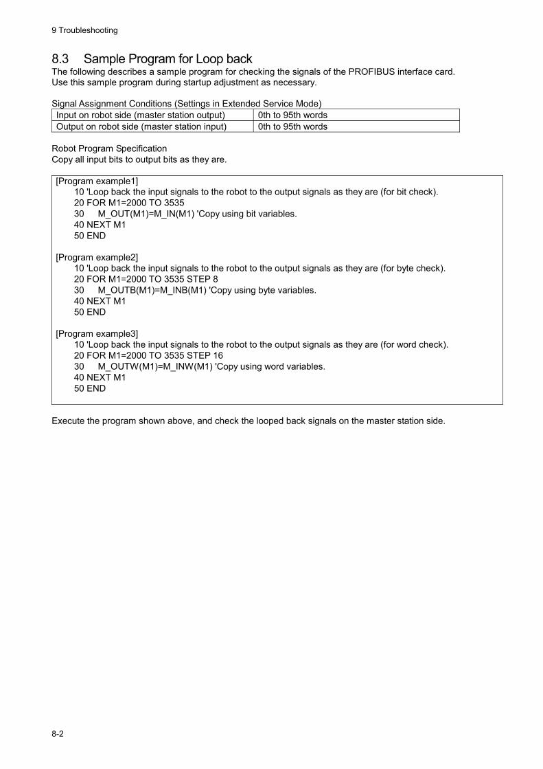
8.3 Sample Program for Loop back The following describes a sample program for checking the signals of the PROFIBUS interface card. Use this sample program during startup adjustment as necessary. Signal Assignment Conditions (Settings in Extended Service Mode) Input on robot side (master station output) 0th to 95th words Output on robot side (master station input) 0th to 95th words
Robot Program Specification Copy all input bits to output bits as they are. [Program example1]
10 'Loop back the input signals to the robot to the output signals as they are (for bit check). 20 FOR M1=2000 TO 3535 30 M_OUT(M1)=M_IN(M1) 'Copy using bit variables. 40 NEXT M1 50 END
[Program example2] 10 'Loop back the input signals to the robot to the output signals as they are (for byte check). 20 FOR M1=2000 TO 3535 STEP 8 30 M_OUTB(M1)=M_INB(M1) 'Copy using byte variables. 40 NEXT M1 50 END
[Program example3] 10 'Loop back the input signals to the robot to the output signals as they are (for word check). 20 FOR M1=2000 TO 3535 STEP 16 30 M_OUTW(M1)=M_INW(M1) 'Copy using word variables. 40 NEXT M1 50 END
Execute the program shown above, and check the looped back signals on the master station side.
9 Troubleshooting
9-1
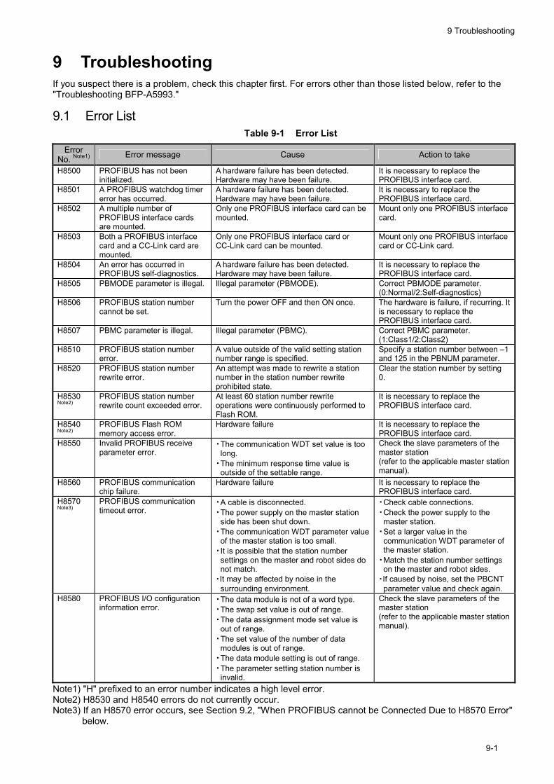
9 Troubleshooting If you suspect there is a problem, check this chapter first. For errors other than those listed below, refer to the "Troubleshooting BFP-A5993."
9.1 Error List Table 9-1 Error List
Error No. Note1) Error message Cause Action to take
H8500 PROFIBUS has not been initialized.
A hardware failure has been detected. Hardware may have been failure.
It is necessary to replace the PROFIBUS interface card.
H8501 A PROFIBUS watchdog timer error has occurred.
A hardware failure has been detected. Hardware may have been failure.
It is necessary to replace the PROFIBUS interface card.
H8502 A multiple number of PROFIBUS interface cards are mounted.
Only one PROFIBUS interface card can be mounted.
Mount only one PROFIBUS interface card.
H8503 Both a PROFIBUS interface card and a CC-Link card are mounted.
Only one PROFIBUS interface card or CC-Link card can be mounted.
Mount only one PROFIBUS interface card or CC-Link card.
H8504 An error has occurred in PROFIBUS self-diagnostics.
A hardware failure has been detected. Hardware may have been failure.
It is necessary to replace the PROFIBUS interface card.
H8505 PBMODE parameter is illegal. Illegal parameter (PBMODE). Correct PBMODE parameter. (0:Normal/2:Self-diagnostics)
H8506 PROFIBUS station number cannot be set.
Turn the power OFF and then ON once. The hardware is failure, if recurring. It is necessary to replace the PROFIBUS interface card.
H8507 PBMC parameter is illegal. Illegal parameter (PBMC). Correct PBMC parameter. (1:Class1/2:Class2)
H8510 PROFIBUS station number error.
A value outside of the valid setting station number range is specified.
Specify a station number between –1 and 125 in the PBNUM parameter.
H8520 PROFIBUS station number rewrite error.
An attempt was made to rewrite a station number in the station number rewrite prohibited state.
Clear the station number by setting 0.
H8530 Note2)
PROFIBUS station number rewrite count exceeded error.
At least 60 station number rewrite operations were continuously performed to Flash ROM.
It is necessary to replace the PROFIBUS interface card.
H8540 Note2)
PROFIBUS Flash ROM memory access error.
Hardware failure It is necessary to replace the PROFIBUS interface card.
H8550 Invalid PROFIBUS receive parameter error.
・ The communication WDT set value is too long.
・ The minimum response time value is outside of the settable range.
Check the slave parameters of the master station (refer to the applicable master station manual).
H8560 PROFIBUS communication chip failure.
Hardware failure It is necessary to replace the PROFIBUS interface card.
H8570 Note3)
PROFIBUS communication timeout error.
・ A cable is disconnected. ・ The power supply on the master station
side has been shut down. ・ The communication WDT parameter value
of the master station is too small. ・ It is possible that the station number
settings on the master and robot sides do not match.
・It may be affected by noise in the surrounding environment.
・ Check cable connections. ・ Check the power supply to the
master station. ・ Set a larger value in the
communication WDT parameter of the master station.
・ Match the station number settings on the master and robot sides.
・If caused by noise, set the PBCNT parameter value and check again.
H8580 PROFIBUS I/O configuration information error.
・ The data module is not of a word type. ・ The swap set value is out of range. ・ The data assignment mode set value is
out of range. ・ The set value of the number of data
modules is out of range. ・ The data module setting is out of range. ・ The parameter setting station number is
invalid.
Check the slave parameters of the master station (refer to the applicable master station manual).
Note1) "H" prefixed to an error number indicates a high level error. Note2) H8530 and H8540 errors do not currently occur. Note3) If an H8570 error occurs, see Section 9.2, "When PROFIBUS cannot be Connected Due to H8570 Error"
below.

9 Troubleshooting
9-2
9.2 When PROFIBUS cannot be Connected Due to H8570 Error 1) Is the power supply to the master station unit ON? 2) Is the master station operating normally?
* If the master station has not been started before turning ON the power supply to the robot controller, an H8570 error occurs.
3) Is the master station connected correctly? 4) Do the parameter settings of the master station match the PROFIBUS signals on the robot side? 5) Is there any noise source in the peripheral devices? 6) To ignore the H8570 error, change the E8500 parameter. 7) Set the same station number of the station number of master station side and robot side. The robot side is
set with the "PBNUM" parameter.

10 Appendix
10-1
10 Appendix 10.1 PROFIBUS Robot (System) Status Variables The following describes the robot (system) status variables relating to PROFIBUS in details. The status of the PROFIBUS Interface can be checked if the monitor of the following system status variable is carried out by robot.
Table 10-1 List of Robot (System) Status Variables Used in PROFIBUS
Variable name Type Name Function Read/Write
M_PBNUM Integer 1 Operating station number The number of the station currently in operation Read
M_PBFNUM Integer 1 Station number setting in the flash ROM
The station number which saved in the flash ROM Read


Oct..2009 MEE Printed in Japan on recycled paper. Specifications are subject to change without notice.
HEAD OFFICE: TOKYO BUILDING, 2-7-3, MARUNOUCHI, CHIYODA-KU, TOKYO 100-8310, JAPANNAGOYA WORKS: 5-1-14, YADA-MINAMI, HIGASHI-KU, NAGOYA 461-8670, JAPAN
Authorised representative: MITSUBISHI ELECTRIC EUROPE B.V. GERMANYGothaer Str. 8, 40880 Ratingen / P.O. Box 1548, 40835 Ratingen, Germany